20 GB/IE/NI/CY/MT
zAdaptation of device to flux-cored welding wire without inert gas
If you are using flux-cored welding wire with integrated inert gas, then you do not have to have an
external inert gas supply.
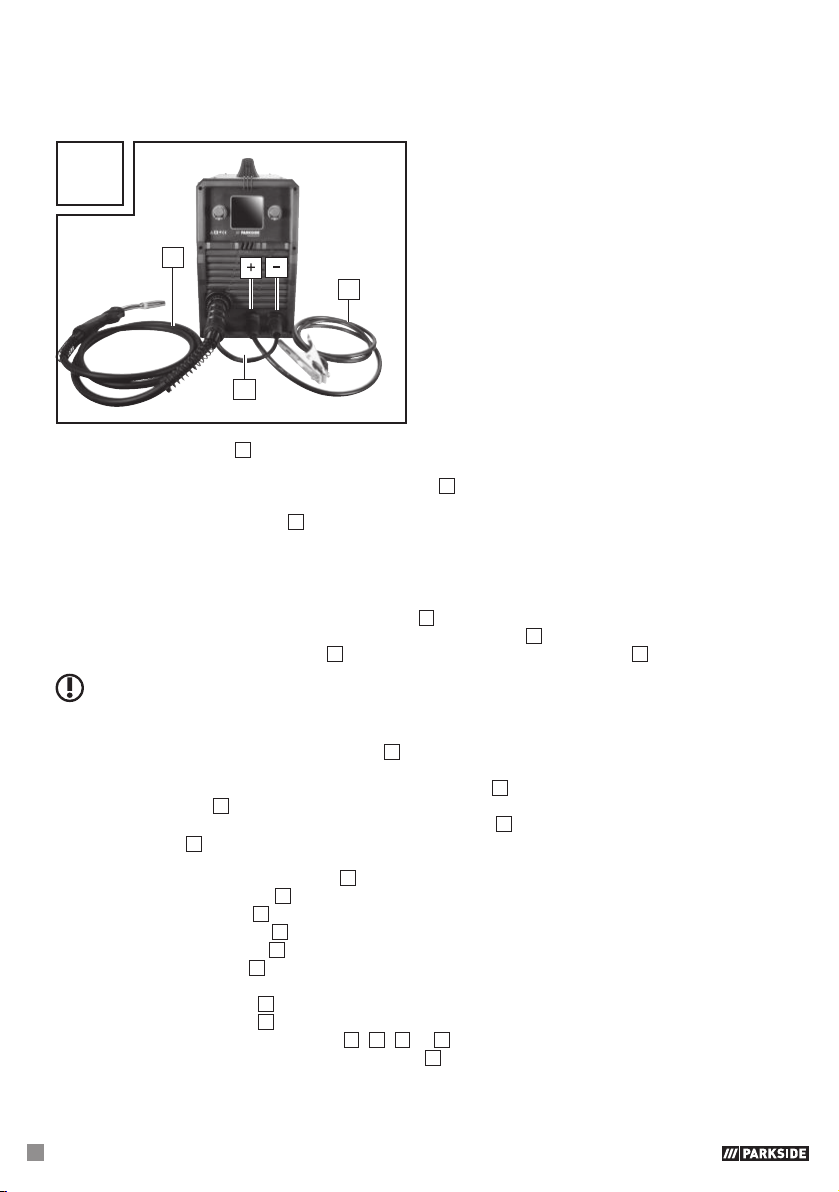
U
7
4
6
First connect the plug 6 with the connector marked with the “-” (see Fig. U). To fix it in place, rotate
in a clockwise direction. If you are in any doubt, then please contact a professional.
Connect the cable assembly with direct connection 7 to the appropriate connector. To fix the
connection, tighten the connection in a clockwise direction.
Then connect the earth cable 4 with the corresponding connector, marked with the “+” (see Fig. U)
and to fix the connection in place, rotate in a clockwise direction.
zInserting welding wire
Unlock and open the cover of the wire feed unit 1, by pushing the release knob upwards.
Unlock the roller unit by turning the fixing for the welding spool 28 anti-clockwise (see Fig. G).
Pull the fixing of the welding spool 28 off the bracket of the welding wire spool 33 (see Fig. G).
PLEASE NOTE: Make sure that the end of the wire does not come loose and cause the roll to roll
out on its own. The end of the wire may not be released until during assembly.
Completely unpack the welding wire spool 32, so that it can unrolled without difficulty. Do not
release the wire end yet.
If the wire roll is approx. 10 cm wide, remove the adapter 35. For wire rolls with a width of approx.
5 cm, the adapter 35 remains in position.
Place the wire roll on the bracket of the welding wire spool 33 . Make sure that the roll unwinds on
the side of the 29 wire feed guide and that the end of the welding wire is below the welding spool
(see Fig. M and N).
Place the fixing of the welding spool 28 back on and lock it by pressing and turning it clockwise.
Undo the adjustment screw 25 and swing it downwards (see Fig. I).
Turn the thrust roller unit 26 to the side (see Fig. J).
Loosen the feed roll holder 27 by turning it anti-clockwise and pull it forwards and off (see Fig. K).
On the top of the feed roll 21, check whether the appropriate wire thickness is indicated. If
necessary, the feed roll 21 has to be turned over or replaced. The welding wire must be positioned
in the upper groove!
Erect the feed roll holder 27 again and screw clockwise direction.
Remove the torch nozzle 8 by pulling and turning it clockwise (see Fig. L).
Unscrew the relevant welding nozzle 17, 18, 19 or 20 (see Fig. L).
Guide the cable assembly with direct connection 7 away from the welding device as straight as
possible (place it on the floor).
Take the wire end out of the edge of the spool.