742782
29
Verklein
Vergroot
Pagina terug
1/58
Pagina verder
Comfort 580 / Control x.51
Operator system for Hinged Gates
GB
Operating Instructions
2 Operating Instructions, Comfort 580 GB (#91636)
1. Meaning of symbols
Caution!
Danger of personal injury!
The following safety advice must
be observed at all times so as to avoid
personal injury!
Attention!
Danger of material damage!
The following safety advice must
be observed at all times so as to avoid
material damage!
Advice / Tip
Check
Reference
i
Photocell or closing edge safety device (CESD)
Gate position OPEN
Has no function
Gate position CLOSED
Reference control point
Has no function
Impulse
(remote control, external control elements)
Operation
Closing edge safety device
STOP
External control elements
Modular antenna
Controls and motor unit symbols Advice
Type plate on motor unit 2 (only double wing)
Type: ________________________________________________
Art. No.: _____________________________________________
Product No.: __________________________________________
Type plate on motor unit 1
Type: ________________________________________________
Art. No.: _____________________________________________
Product No.: __________________________________________
Type plate on control unit
Type: ________________________________________________
Art. No.: _____________________________________________
Product No.: __________________________________________
Operating Instructions, Comfort 580 GB (#91636) 3
2. Table of contents
1. Meaning of symbols . . . . . . . . . . . . . . . . . . . . . . . . . . . . . . . . . . . . . . . . . . . . . . . . . . . . . . . . . . . . . . . . . . . .2
2. Table of contents . . . . . . . . . . . . . . . . . . . . . . . . . . . . . . . . . . . . . . . . . . . . . . . . . . . . . . . . . . . . . . . . . . . . . . .3
3. General safety advice . . . . . . . . . . . . . . . . . . . . . . . . . . . . . . . . . . . . . . . . . . . . . . . . . . . . . . . . . . . . . . . . . . .4
4. Product overview . . . . . . . . . . . . . . . . . . . . . . . . . . . . . . . . . . . . . . . . . . . . . . . . . . . . . . . . . . . . . . . . . . . . . .5
4.1 Comfort 580 supply package . . . . . . . . . . . . . . . . . . . . . . . . . . . . . . . . . . . . . . . . . . . . . . . . . . . . . . . . . .5
4.2 Dimensions . . . . . . . . . . . . . . . . . . . . . . . . . . . . . . . . . . . . . . . . . . . . . . . . . . . . . . . . . . . . . . . . . . . . . . .6
4.3 Gate variations . . . . . . . . . . . . . . . . . . . . . . . . . . . . . . . . . . . . . . . . . . . . . . . . . . . . . . . . . . . . . . . . . . . . .7
5. Preparation for mounting . . . . . . . . . . . . . . . . . . . . . . . . . . . . . . . . . . . . . . . . . . . . . . . . . . . . . . . . . . . . . . .7
5.1 General notes . . . . . . . . . . . . . . . . . . . . . . . . . . . . . . . . . . . . . . . . . . . . . . . . . . . . . . . . . . . . . . . . . . . . .7
5.2 Checks . . . . . . . . . . . . . . . . . . . . . . . . . . . . . . . . . . . . . . . . . . . . . . . . . . . . . . . . . . . . . . . . . . . . . . . . . . .8
5.3 Gate and foundation layout . . . . . . . . . . . . . . . . . . . . . . . . . . . . . . . . . . . . . . . . . . . . . . . . . . . . . . . . . . .9
5.4 Cabling layout . . . . . . . . . . . . . . . . . . . . . . . . . . . . . . . . . . . . . . . . . . . . . . . . . . . . . . . . . . . . . . . . . . . .10
6. Installation . . . . . . . . . . . . . . . . . . . . . . . . . . . . . . . . . . . . . . . . . . . . . . . . . . . . . . . . . . . . . . . . . . . . . . . . . . .11
6.1 Mounting conditions . . . . . . . . . . . . . . . . . . . . . . . . . . . . . . . . . . . . . . . . . . . . . . . . . . . . . . . . . . . . . . .11
6.2 Installing the foundation box . . . . . . . . . . . . . . . . . . . . . . . . . . . . . . . . . . . . . . . . . . . . . . . . . . . . . . . . .11
6.3 Installing the motor unit . . . . . . . . . . . . . . . . . . . . . . . . . . . . . . . . . . . . . . . . . . . . . . . . . . . . . . . . . . . .13
6.4 Mounting the telescopic arm . . . . . . . . . . . . . . . . . . . . . . . . . . . . . . . . . . . . . . . . . . . . . . . . . . . . . . . . .14
6.5 Release . . . . . . . . . . . . . . . . . . . . . . . . . . . . . . . . . . . . . . . . . . . . . . . . . . . . . . . . . . . . . . . . . . . . . . . . .15
6.6 Fixing the control unit . . . . . . . . . . . . . . . . . . . . . . . . . . . . . . . . . . . . . . . . . . . . . . . . . . . . . . . . . . . . . .15
6.7 Connection of control elements . . . . . . . . . . . . . . . . . . . . . . . . . . . . . . . . . . . . . . . . . . . . . . . . . . . . . .16
6.8 Connecting the motor unit to the controls . . . . . . . . . . . . . . . . . . . . . . . . . . . . . . . . . . . . . . . . . . . . . . .21
6.9 Connection of the mains cable . . . . . . . . . . . . . . . . . . . . . . . . . . . . . . . . . . . . . . . . . . . . . . . . . . . . . . .24
7. Hand transmitter . . . . . . . . . . . . . . . . . . . . . . . . . . . . . . . . . . . . . . . . . . . . . . . . . . . . . . . . . . . . . . . . . . . . . .25
7.1 Operation and accessories . . . . . . . . . . . . . . . . . . . . . . . . . . . . . . . . . . . . . . . . . . . . . . . . . . . . . . . . . . .25
7.2 Hand transmitter coding . . . . . . . . . . . . . . . . . . . . . . . . . . . . . . . . . . . . . . . . . . . . . . . . . . . . . . . . . . . .26
8. Initial operation . . . . . . . . . . . . . . . . . . . . . . . . . . . . . . . . . . . . . . . . . . . . . . . . . . . . . . . . . . . . . . . . . . . . . . .28
8.1 Connecting the modular antenna . . . . . . . . . . . . . . . . . . . . . . . . . . . . . . . . . . . . . . . . . . . . . . . . . . . . .28
8.2 Overview of the control unit . . . . . . . . . . . . . . . . . . . . . . . . . . . . . . . . . . . . . . . . . . . . . . . . . . . . . . . . .28
8.3 Overview of the display functions . . . . . . . . . . . . . . . . . . . . . . . . . . . . . . . . . . . . . . . . . . . . . . . . . . . . .29
8.4 Reference point . . . . . . . . . . . . . . . . . . . . . . . . . . . . . . . . . . . . . . . . . . . . . . . . . . . . . . . . . . . . . . . . . . .29
8.5 Express programming . . . . . . . . . . . . . . . . . . . . . . . . . . . . . . . . . . . . . . . . . . . . . . . . . . . . . . . . . . . . . .30
8.6 Function test . . . . . . . . . . . . . . . . . . . . . . . . . . . . . . . . . . . . . . . . . . . . . . . . . . . . . . . . . . . . . . . . . . . . .33
9. Extended operator functions . . . . . . . . . . . . . . . . . . . . . . . . . . . . . . . . . . . . . . . . . . . . . . . . . . . . . . . . . . . .34
9.1 General notes on extended operator functions . . . . . . . . . . . . . . . . . . . . . . . . . . . . . . . . . . . . . . . . . . .34
9.2 Programming structure for extended operator functions (Example for Level 2, Menu 2) . . . . . . . . . . . . .35
9.3 General overview of the programmable functions . . . . . . . . . . . . . . . . . . . . . . . . . . . . . . . . . . . . . . . . .36
9.4 Functions overview for the levels . . . . . . . . . . . . . . . . . . . . . . . . . . . . . . . . . . . . . . . . . . . . . . . . . . . . . .38
10. Messages . . . . . . . . . . . . . . . . . . . . . . . . . . . . . . . . . . . . . . . . . . . . . . . . . . . . . . . . . . . . . . . . . . . . . . . . . . . .48
10.1 Status messages . . . . . . . . . . . . . . . . . . . . . . . . . . . . . . . . . . . . . . . . . . . . . . . . . . . . . . . . . . . . . . . . . .48
10.2 Fault messages . . . . . . . . . . . . . . . . . . . . . . . . . . . . . . . . . . . . . . . . . . . . . . . . . . . . . . . . . . . . . . . . . . . .48
10.3 Rectifying faults . . . . . . . . . . . . . . . . . . . . . . . . . . . . . . . . . . . . . . . . . . . . . . . . . . . . . . . . . . . . . . . . . . .50
11. Attachment . . . . . . . . . . . . . . . . . . . . . . . . . . . . . . . . . . . . . . . . . . . . . . . . . . . . . . . . . . . . . . . . . . . . . . . . . .53
11.1 Connection diagram Comfort 580 . . . . . . . . . . . . . . . . . . . . . . . . . . . . . . . . . . . . . . . . . . . . . . . . . . . . .53
11.2 Technical data for Comfort 580 . . . . . . . . . . . . . . . . . . . . . . . . . . . . . . . . . . . . . . . . . . . . . . . . . . . . . . .54
11.3 Declaration of Incorporation . . . . . . . . . . . . . . . . . . . . . . . . . . . . . . . . . . . . . . . . . . . . . . . . . . . . . . . . .55
11.4 EC Declaration of Conformity . . . . . . . . . . . . . . . . . . . . . . . . . . . . . . . . . . . . . . . . . . . . . . . . . . . . . . . .56
4 Operating Instructions, Comfort 580 GB (#91636)
Please read carefully!
IMPORTANT SAFETY INSTRUCTIONS:
IMPORTANT - PLEASE OBSERVE ALL SAFETY INSTRUCTIONS TO PRE-
VENT INJURY TO PERSONS.
PLEASE KEEP THESE INSTRUCTIONS FOR FURTHER USE.
IMPORTANT INSTRUCTIONS FOR SAFE INSTALLATION:
IMPORTANT - INCORRECT INSTALLATION CAN RESULT IN SERIOUS
INJURY. PLEASE FOLLOW ALL INSTALLATION INSTRUCTIONS.
Target group
This operator system may only be installed, connected and put into
operation by qualified and trained professionals!
Qualified and trained specialist personnel are persons
- who have knowledge of the general and special safety regulations,
- who have knowledge of the relevant electro-technical regulations,
- with training in the use and maintenance of suitable safety equipment,
- who are sufficiently trained and supervised by qualified electricians,
- who are able to recognise the particular hazards involved when
working with electricity,
- with knowledge regarding applications of the EN 12635 standard
(installation and usage requirements).
Warranty
For an operations and safety warranty, the advice in this instruction
manual has to be observed. Disregarding these warnings may lead
to personal injury or material damage. If this advice is disregarded,
the manufacturer will not be liable for damages that might occur.
Batteries, fuses and bulbs are excluded from warranty.
To avoid installation errors and damage to the gate and operator
system, it is imperative that the installation instructions are followed.
The system may only be used after thoroughly reading the respective
mounting and installation instructions.
The motor unit may not be opened, otherwise the guarantee is void.
The installation and operating instructions are to be given to the
gate system user, who must keep them safe. They contain important
advice for operation, checks and maintenance.
This item is produced according to the directives and standards
mentioned in the Manufacturer's Declaration and in the Declaration
of Conformity. The product has left the factory in perfect condition
with regard to safety.
Power-operated windows, doors and gates must be checked by an
expert (and this must be documented) before they are put into
operation and thereafter as required, but at least once a year.
Correct use
The operator system is designed exclusively for opening and closing
hinged doors and gates.
Gate requirements
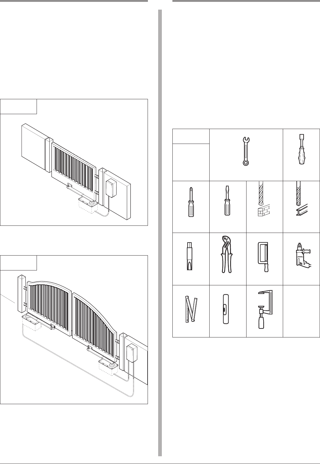
The Comfort 580 operator system is suitable for:
- hinged gates with a gate wing width of 2.50 m and a gate wing
weight of 250 kg.
Beside the advice in these instructions, please observe the
general safety and accident prevention regulations!
Our sales and supply terms and conditions are effective.
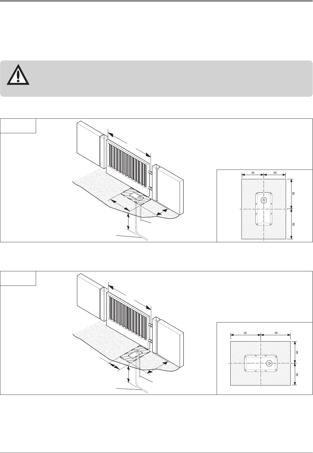
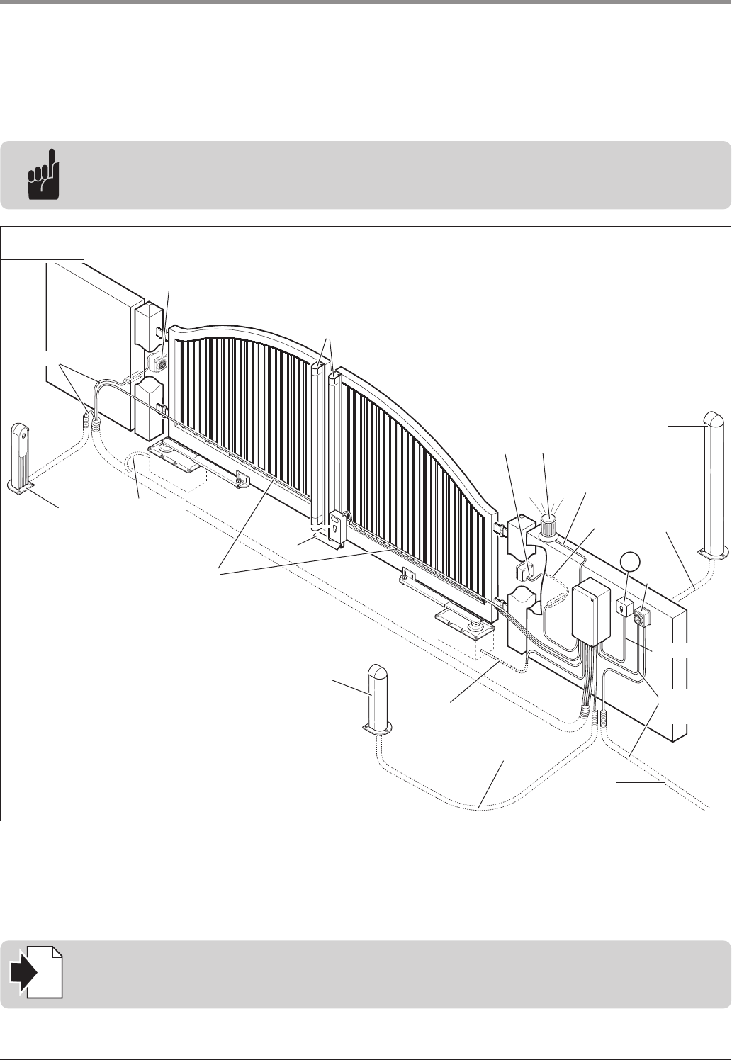
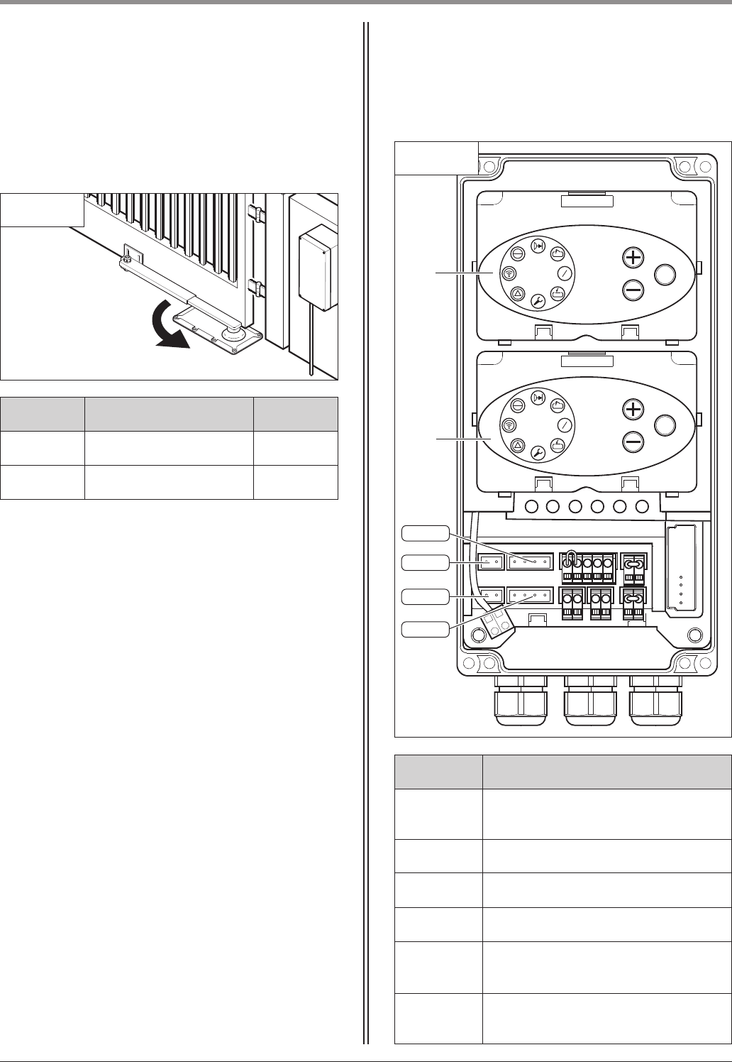
Information on installing the operator system
• Ensure that the gate is in good mechanical condition.
• Ensure that the gate opens and closes properly.
• Remove all unnecessary components from the gate (e.g. cables,
chains, brackets).
• Render any installations inoperable that will no longer be needed
after the operator system has been installed.
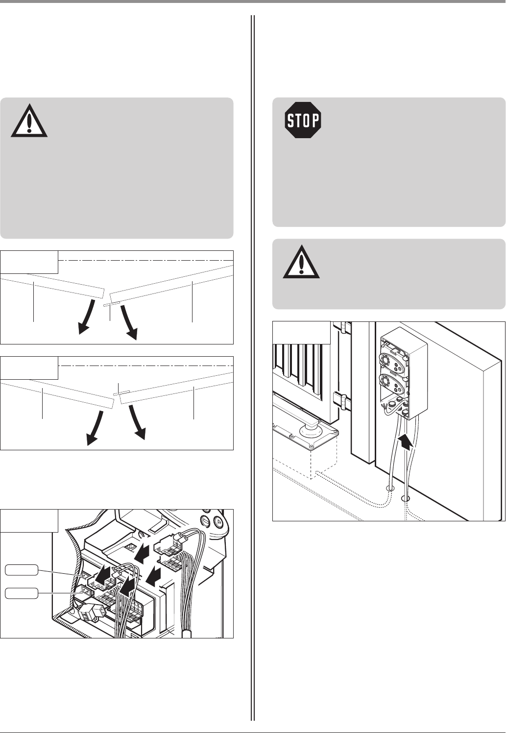
• Before commencing cabling works it is very important to disconnect
the operator system from the electricity supply.
Ensure that the electricity supply remains disconnected throughout
the cabling works.
• Adhere to the local protection regulations.
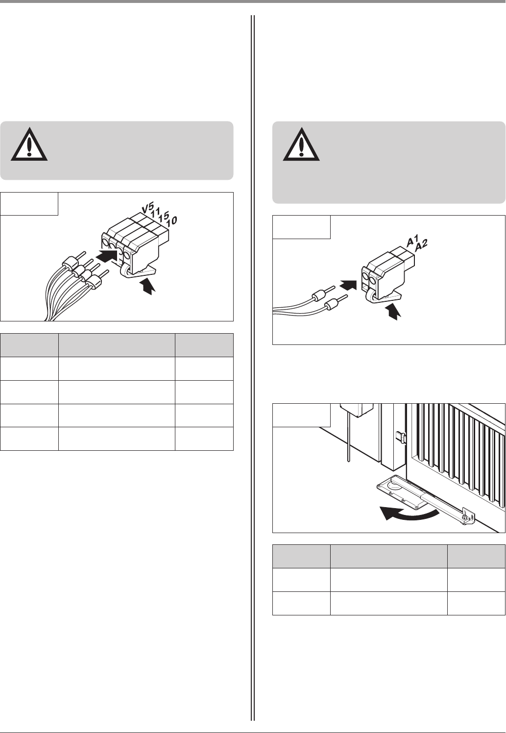
• Lay the electricity supply cables and control cables; these MUST be
laid separately. The controls voltage is 24 V DC.
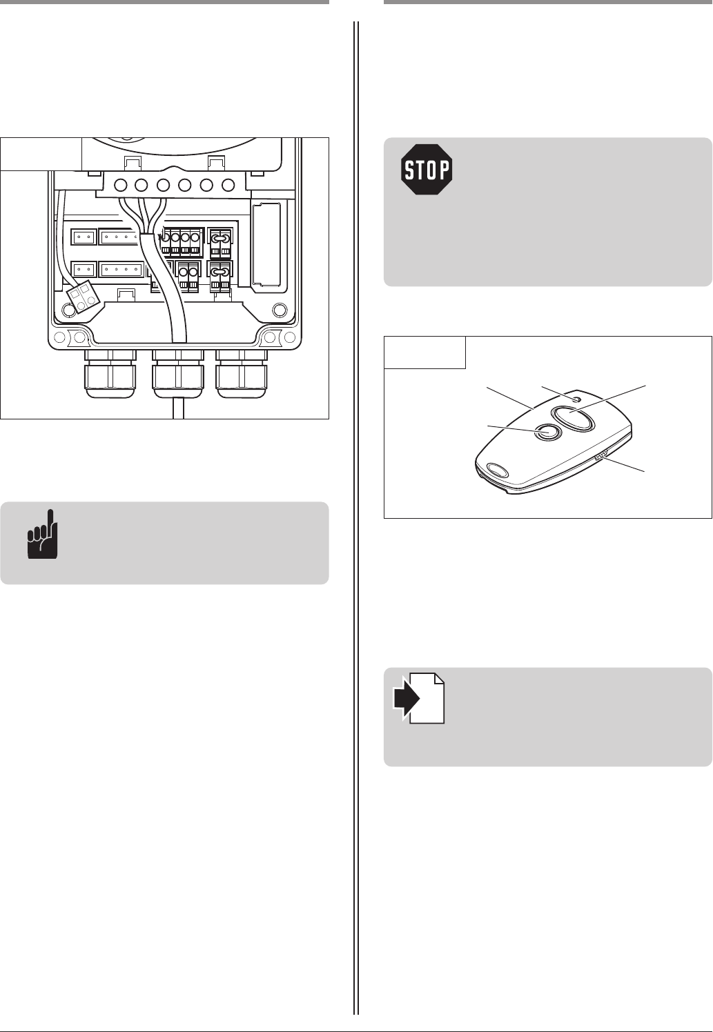
• Install all the impulse transmitters and control devices (e.g. remote
control buttons) within sight of the gate and at a safe distance
from the moving parts of the gate. A minimum installation height
of 1.5 m must be observed.
• Ensure that no part of the gate extends across public footways or
roads when the installation is complete.
Information on commissioning the operator system
After initial operation, the persons responsible for operating the gate
system, or their representatives must be familiarised with the use of
the system.
• Make sure that children cannot access the gate control unit.
• Before moving the gate, make sure that there are neither persons
nor objects in the operating range of the gate.
• Test all existing emergency command devices.
• Never insert your hands into a running gate or moving parts.
• Pay attention to any parts of the gate system that could cause
crushing or shearing damage or accidents.
The EN 13241-1 regulations must be observed.
Information on servicing the operator system
To ensure proper operation, the following items must be checked
regularly and repaired if necessary.
Before any works to the gate system are undertaken, the operator
system must be disconnected from the mains.
• Check once a month that the operator system stops and reverses
in every position when the gate touches an obstacle. Place an
obstacle in the path of the gate to check this.
• Check the settings of the OPEN and CLOSE automatic cut-out
function.
• Check all movable parts of the gate and operator system.
• Check the gate system for signs of wear or damage.
• Check whether the gate can be easily moved by hand.
• Inspect the telescopic arms for dirt and corrosion.
Remove any dirt. Grease the sliding seats on the telescopic arms.
Information on cleaning the operator system
Never use water jets, high pressure cleaners, acids or bases for
cleaning.
3. General safety advice
Operating Instructions, Comfort 580 GB (#91636) 5
4.1 Comfort 580 supply package
4. Product overview
4.1 / 1
1
2
Single wing gate system
1 Foundation box
2 Motor unit
3 Telescopic arm
4 Shims (4x)
5 Spacer cylinder
6 Cover plate
7 Protective rubber fitting
8 Set of screws for bracket
4.1 / 3
9 Control x.51
10 Handle
1 Foundation box (2x)
2 Motor unit (2x)
3 Telescopic arm (2x)
4 Shims (8x)
5 Spacer cylinder (2x)
6 Cover plate (2x)
7 Protective rubber fitting (2x)
8 Set of screws for bracket (2x)
Double wing gate system
Control unit
3
4
5
The Comfort 580 standard delivery package comprises:
- motor unit
- controls
- fixing materials for controls
and motor unit
- remote control
The Comfort 580 is available in the following versions,
as required:
9
6
7
8
1
2
3
4
5
6
7
8
4.1 / 2
6 Operating Instructions, Comfort 580 GB (#91636)
4. Product overview
!
5
!”
!#
4.1 / 4
11 Screws 3.5 x 32 (4x)
12 Wall plugs S6 (4x)
13 13 Spacer elements (2x)
14 Screw fixing insert with 2 flat cable openings
15 M20 screw fixing with flat cable insert
16 M20 screw fixing with round cable insert
17 M16 screw fixing with round cable insert
Mounting kit for control unit
!^
4.1 / 5
18 Hand transmitter
19 Sun visor clip
20 Module antenna
21 Transmission plug
Remote control
!\
„¯
4.2 / 1
Comfort 580
4.2 Dimensions
„∏
150
300
168
112
270
72
8
Operating Instructions, Comfort 580 GB (#91636) 7
4.3 / 1
The standard supply package is suitable for
the following types of gate.
Single wing gate system
4.3 / 2
Double wing gate system
5.1 General notes
The pictures in these instructions are not true-to-scale.
Dimensions are always given in millimetres (mm)!
The motor unit and the controls must be mounted on
the inside of the gate system.
For correct mounting you will need the following
tools:
5.1 / 1
13 / 17 / 22 / 24 13
2 2 / 5 ø 6 ø 6.5
M 8
5. Preparation for mounting
4.3 Gate variations
4. Product overview
8 Operating Instructions, Comfort 580 GB (#91636)
5.2 Checks
Attention!
In order to guarantee correct
mounting, carry out the following
checks before installing.
5. Preparation for mounting
Advice:
The use of an electric lock is
recommended.
Foundations
• Check the proposed position of the foundation.
Supply package
• Check the package to ensure that all the parts are
included.
• Check that you have all the additional components
that are necessary for your particular installation
requirements.
Gate system
• Ensure that your gate system has an appropriate
electricity supply connection and a facility for
disconnecting the mains. The minimum cross-
sectional area of the earth cable is 3 x 1.5 mm
2
.
• Ensure that all cables are suitable for outdoor use
(UV resistant and cold resistant).
• Ensure that your gate system has a gate stop in the
CLOSE and OPEN directions.
• Disassemble the door latches or render them inop-
erable.
• Ensure that the gate can be easily moved by hand.
• Observe the following gate requirements.
Gate wing width: min. 1 m - max. 2.5 m
Gate height: max. 2.5 m
Gate wing weight: max. 250 kg
Open space: min. 50%
Gate incline: The gate must be horizontal.
Operating Instructions, Comfort 580 GB (#91636) 9
5. Preparation for mounting
A Conduit for control cable
B Drainage pipe for foundation box
q Gate length (max. 2.50 m)
r Below the depth of frost penetration
5.3 Gate and foundation layout
r
A
B
5.3 / 1
Attention!
In order to avoid damage to the foundation,
- the specified size of the foundation must be adhered to,
- the foundation box must be positioned at the centre of the foundation.
Motor unit parallel to the gate
r
q
A
B
5.3 / 2
Motor unit at right angles to the gate
q
>250
> 400
>250
>400
10 Operating Instructions, Comfort 580 GB (#91636)
5. Preparation for mounting
5.4 Cabling layout
5.4 / 1
2 x 0.75 mm
2
8 x 0.75 mm
2
8 x 0.75 mm
2
2 x 0.4 mm
2
2 x 0.4 mm
2
2 x 0.4 mm
2
2 x 0.4 mm
2
3 x 1.5 mm
2
230 V / AC
3 x 1.5 mm
2
Advice:
This is just an example of a cabling layout; the layout can vary according to the type of gate and the
associated equipment.
Reference:
The relevant instructions are to be followed for the installation and cabling of the gate sensors and
the operating and safety elements.
i
1 Photocell
2 Photocell
3 Signal light
4 Code button, transponder, ...
5 Key switch
6 Mains isolator switch (mains disconnection facility)
7 Electric lock
8 Stop plate
9 Mains supply cable
10 Closing edge safety device (CESD)
2
23
4
6
9
7
1
1
8
5
Operating Instructions, Comfort 580 GB (#91636) 11
6.1 Mounting conditions
6.1 / 1
Mounting position of motor unit
Attention!
To ensure proper operation,
- the foundation box must be concreted
in place in a foundation block,
- all the specified conditions must be
met,
- all the specified dimensions must be
complied with.
6.1 / 2
The distance between the upper edge of the foundation
box and the lower edge of the gate wing must be at
least 55 mm.
6.2 Installing the foundation box
• Place the foundation box (A) in the prepared opening.
• Position the foundation box (A) in the middle of the
opening. Observe the specified installation conditions.
• Connect the conduit (B) for the control cable to the
foundation box (A).
• Connect the drainage pipe (C) to the foundation
box.
• Seal the joints where the conduit (B) and the drainage
pipe (C) connect to the foundation box (A).
6.2 / 1
• Place the spacer cylinder (D) in the foundation box (A).
6.2 / 2
Clearance between gate wing and ground
Advice:
For greater clearance values, a suitable
fitting must be fixed to the gate.
≤ 100430 - 470
0 - 40
> 55
A
B
C
A
D
6. Installation
12 Operating Instructions, Comfort 580 GB (#91636)
6. Installation
• Close the foundation box (A) with the cover plate (E).
• Seal the cover plate (E) using self-adhesive tape.
6.2 / 3
A
E
• Infill the space surrounding the foundation box with
concrete.
6.2 / 4
Advice:
To ensure that the motor unit functions
properly, the foundation box must not
be allowed to change position during
concreting.
• Check that the foundation box is horizontal.
• Allow the foundation concrete to set.
• Remove the self-adhesive tape and the cover plate (E).
• Remove the spacer cylinder (D).
6.2 / 5
Attention!
To prevent damage to the foundations
occurring and the drive position from
slipping, the foundation block must
have set completely before the next
step is carried out.
D
E
Operating Instructions, Comfort 580 GB (#91636) 13
6. Installation
6.3 / 1
Attention!
To allow the motor unit to be taken
out at a later date, at least 35 cm of
control cable must be left loose in the
foundation box.
6.3 Installing the motor unit
• Place the four galvanised shims (A) in the corners of
the foundation box (B).
6.3 / 2
• Feed the control cable through the conduit.
• Pull the cable through to its connection position at
the control unit.
• Lower the motor unit (C) into the foundation box (B).
A
B
B
C
Tip:
If the motor unit has to be taken out of
the foundation box at a later date, two
of the screws can be replaced with the
longer screws (supplied) to make this
process easier. Before lowering the
motor unit back into the foundation
box, the short screws must be put back
into place.
6.3 / 3
14 Operating Instructions, Comfort 580 GB (#91636)
6. Installation
6.4 / 1
6.4 Mounting the telescopic arm
• Place the protective rubber fitting (B) on the telescopic
arm (C).
• Push the protective rubber fitting (B) tightly onto the
motor unit.
• Push the telescopic arm (C) on to the motor unit (A).
Advice:
The telescopic arm must be mounted
between the OPEN and CLOSED
positions. The mounting position
ensures that the reference point is
switched with every gate movement.
B
A
C
6.4 / 2
• Drive the gate to the gate OPEN position.
• Drive the gate to the gate CLOSED position
If the telescopic arm has an overlap of at least
90 mm whatever the gate position, the bracket can
be screwed to the gate.
• Screw the bracket to the gate.
C
> 90
Before the telescopic arm can be permanently fixed to
the gate, the correct position for the bracket screws
must be determined. In order to adjust the bracket
position, the motor unit must first be connected to the
control unit.
• Clamp the bracket of the telescopic arm (C) securely
to the gate using a screw clamp.
• Connect the motor unit to the control unit.
• Put the control unit into operation.
Reference:
Connecting the motor unit to the
control unit is described in Section 6.8.
Putting the control unit into operation
is described in Sections 8.1 to 8.6.
i
Operating Instructions, Comfort 580 GB (#91636) 15
6. Installation
6.6 / 1
6.6 Fixing the control unit
6.5 Release
• Open the control unit.
• Mount the control unit using the spacer elements (A).
3.5 x 32
Attention!
The control unit must be installed in
such a way that the motor cable can be
fed through the screw fixing at the
base of the control unit.
6.6 / 2
A
Reference:
Mounting the telescopic arm is
described in Section 6.4.
i
Releasing
• Remove the screw (A) and the spacer.
• Pull out the telescopic arm (B).
• Lift the remaining section of the telescopic arm off
the motor unit.
6.5 / 1
B
A
Tip:
If the telescopic arm can not be
separated from the motor unit, an
M12 x 35 screw can be screwed into
the screw thread (C). This will lift the
telescopic arm off the motor unit.
Before mounting the telescopic arm on
the motor unit again, this screw must
be removed.
The motor unit is now no longer coupled to the gate.
The gate can be moved manually.
Locking
To couple up the gate again, the telescopic arm must
be mounted on the motor unit again and fixed to the
bracket.
C
16 Operating Instructions, Comfort 580 GB (#91636)
6. Installation
6.7 Connection of control elements
Attention!
In order to avoid damaging the
controls:
- The local safety regulations must be
complied with at all times.
- It is very important that mains cables
are laid separately from control cables.
- The controls voltage must be 24 V DC.
- If external voltages are applied at
terminals XM70A, XV51A, XM70B,
XV51B, XB99, XP54B, XP54A, XP62B,
XP62A or XB70, the entire electronic
system will be destroyed.
- Only potential-free contacts may be
connected to terminals B9, 5, 34, 3
and 8 (XB99).
- The connections XM70B and XV51B
are not to be used!
Caution!
Danger of electric shock:
Before any cabling works begin, it must
be ensured that the cables are
disconnected from the power supply.
During cabling works, it must be
ensured that the cables remain
disconnected from the power supply at
all times (e.g. prevent reconnection).
Label Type / function
i
XB70 Connection of modular antenna 8.1
XB99
Connection of external control
elements
6.7 / 2
6.7 / 3
6.7 / 4
6.7 / 5
XH01
Connection for programmable
output 16/17 (e.g. signal light,
24 V DC, 0,5 A)
Wiping impulse 15/16
6.7 / 6
6.7 / 7
XM70A
Connection for motor unit
(MASTER)
6.8 / 4
6.8 / 7
XM70B
Connection for motor unit
(SLAVE)
6.8 / 4
6.8 / 7
XN70
Connection Battery Backup
(if available)
-
XN81 Connection for mains cable
6.7 / 6
6.9
XP54A
Connection for closing edge
safety device, gate travelling
direction CLOSE
6.7 / 8
XP54B
Connection for closing edge
safety device, gate travelling
direction OPEN
6.7 / 8
XP62A
Connection for photocell,
gate travelling direction CLOSE
6.7 / 9
XP62B
Connection for photocell,
gate travelling direction OPEN
6.7 / 9
XV51A
Connection for rpm detector
and reference point sensor
(MASTER)
6.8 / 3
6.8 / 7
XV51B
Connection for rpm detector
and reference point sensor
(SLAVE)
6.8 / 3
6.8 / 7
6.7 / 1
XN81
XV51B
XM70B
XM70A
XV51A
XB99
XP54A
XB70
XP54B
XH01
XP62A
XN70 XP62B
Operating Instructions, Comfort 580 GB (#91636) 17
6. Installation
Connection option 2:
Reference:
The connection configuration depends
on the programming of the special
functions. Depending on the program-
ming, impulse or direction buttons can
be connected.
Programming the special functions is
described in Section 9.4 (Level 5).
i
-SB5
12 11
-SB3
14 13
-SB3 4
12 11
-SB8
14 13
-XB99
B9 5 34 3 8
6.7 / 4
Label Type / function
3 Connection for intermediate position
5 Stop connection
8 Impulse connection
34 Connection for closing prevention device
B9 +24 V DC connection
SB3 Button for intermediate position
SB5 STOP button
SB8 Impulse button
SB34
Button for closing prevention device /
Drive system stops and reverses
M06E039
-XB99
B9 5 34 3 8
M06E039
Terminal XB99
Factory settings:
B9 and 5 bridged
Connection option 1:
-SB5
12 11
-SB8
14 13
-XB99
B9 5 34 3 8
6.7 / 2
6.7 / 3
M06E039
Reference:
When installing external control
elements, or safety and signal
equipment, the relevant instructions
must be observed.
i
18 Operating Instructions, Comfort 580 GB (#91636)
- XB99
B9 5
34
3 8
- XH01
15 16 17
- X1
+
-
- S1
14 13
1 2
M07E027
6. Installation
Advice:
If a closing prevention device
(photocell, timer, …) is connected to
XB99, the controls will recognise it
automatically after “Mains On”
(contact SB34 must be closed).
The photocell can be deactivated later
(Level 8 / Menu 1).
When the contacts of a closing
prevention device are open, the gate
can no longer be closed.
Additional external control elements,
and safety and signal devices with 24 V
connections must be connected to
XB99 and XH01.
Connection option 3:
- External radio receiver
6.7 / 5
Label Type / function
XB99 Connection of external control elements
3 Connection for intermediate position
5 Stop connection
8 Impulse connection
34 Connection for closing prevention device
B9 24 V DC connection
X1 Connection for external receiver
1
Connection of potential-free normally open
contact
2
Connection of potential-free normally open
contact
+ 24 V DC connection
- GND connection
S1
Normally open contact, receiver,
potential-free
XH01 Connection of control unit output
15 Connection for electric lock, 24 V DC
16 GND connection
17 Connection for programmable output
Operating Instructions, Comfort 580 GB (#91636) 19
Terminals XN81/XH01 Connection option:
- Connection for signal light with external relay
6. Installation
- XN81
- X0
L
PE
N
N
L
PE
- F0
L
N
PE
6.7 / 6
16
15
17
- YH15
- HH17
- XH01
- XH01
16
15
17
1411
12
A2 A1
- KH17
- HH14
L
N
M07E039
M07E038
6.7 / 7
M07E038
Label Type / function
L Connection for phase
N Connection for neutral wire
PE Earth wire connection
15 / 16 Connection for electric lock, 24 V DC
16 GND connection
16 / 17
Connection of programmable output
(24 V DC / 0.5 A)
HH14 Signal light
HH17 Signal light 24 V
KH17 User’s relay 24 V
YH15 Electric lock (provided by the customer)
20 Operating Instructions, Comfort 580 GB (#91636)
Terminals XP54A / XP54B
Label Type / function
P5 GND connection
46
Connection for signal of closing edge safety
device
Gate travelling direction OPEN (XP54B)
47
Connection for signal of closing edge safety
device
Gate travelling direction CLOSE (XP 54A)
Attention!
If an 8.2 kΩ contact strip closing edge
safety device is connected, the 8.2 kΩ
resistors installed at terminals XP54B
closing edge OPEN and XP54A closing
edge CLOSE must be removed.
Label Type / function
P6 GND connection
26
Connection for photocell signal
gate travelling direction OPEN (XP62B)
27
Connection for signal of photocell, gate
travelling direction CLOSE (XP62A)
RX Receiver for the two-wire photocell
TX Transmitter for the two-wire photocell
Terminals XP62A / XP62B
- XP54B
P5
46
- XP54A
P5 47
8K2
8K2
- XP54B
P5
46
8K2
M07E037
6.7 / 8
- XP62A
P6 27
TX
RX
- W1
2
1
- W2
2
1
1
2
- W1
- W2
- AP27
-
- XP62B
P6 26
TX
RX
- W1
2
1
- W2
2
1
- AP26
M07E036
6.7 / 9
6. Installation
Operating Instructions, Comfort 580 GB (#91636) 21
6. Installation
Advice:
A two-wire photocell connected to
terminals XP62B / XP62A will be
recognised automatically by the
controls after “Mains On”.
The photocell can be deactivated later
(Level 8 / Menu 1).
If the contacts of a closing prevention
device are open, the gate can no longer
be closed.
6.8 Connecting the motor unit to the
controls
6.8 / 1
Advice:
For double wing gate systems, both
motor supply cables must be laid to the
control unit.
6.8 / 2
• Feed the cables from the motor units into the control
unit through the screw fixings.
Attention!
In order to guarantee the protection
grade of the controls, the cable must
be passed through the correct screw
fixing.
22 Operating Instructions, Comfort 580 GB (#91636)
6.8 / 4
Attention!
To ensure that the operator system
functions properly, the rotational
direction of the motor unit must be
taken into consideration when
connecting the motor leads.
6.8 / 5
Terminal Colour system
Number
system
A1 White lead 1
A2 Brown lead 2
The operator system turns the gate clockwise to
OPEN it
Terminal XM70A/XM70B
• Fix the leads in the rpm detector plug.
6.8 / 3
Attention!
To ensure that the operator system
functions properly, the polarity of the
plugs must be correct.
Terminal Colour system
Number
system
V5 Red lead / Grey lead 3 / 6
11 Black lead 4
15 Blue lead 7
10 Pink lead / Lilac lead
5 / 8
6. Installation
Terminal XV51A/XV51B
Operating Instructions, Comfort 580 GB (#91636) 23
6. Installation
• Fix the leads in the motor plugs.
6.8 / 6
Terminal Colour system
Number
system
A1 Brown lead 2
A2 White lead 1
The operator system turns the gate anticlockwise
to OPEN it
6.8 / 7
B
C
XV51B
XM70B
XM70A
XV51A
Label Type / function
B
Control module SLAVE
(only for double wing gates)
C Control module MASTER
XM70A Connection for motor unit (Master)
XM70B Connection for motor unit (Slave)
XV51A
Connection for RPM/
reference point sensor (MASTER)
XV51B
Connection for RPM/
reference point sensor (SLAVE)
Attention!
In order to guarantee the protection
grade of the controls, the cable must
be passed through the correct screw
fixing.
6.9 / 1
• Feed the cable through the screw fitting into the
control unit.
6.9 Connection of the mains cable
Caution!
- During cabling works, the supply
cables must be disconnected from the
power supply. It must be ensured that
the cables remain disconnected from
the supply for the duration of the
cabling works.
- The fixed connection of a mains
supply requires a universally poled
mains disconnection facility.
6.8 / 8
6.8 / 9
D
Attention!
If the gate system is to function
properly, the following points must be
assured:
- For single wing gate systems, the
motor unit must always be connected
to the MASTER terminal (XM70A and
XV51A).
- For double wing gate systems, the
overlapping (D) must be observed
when connecting the motor units.
E Motor unit SLAVE
F Motor unit MASTER
6.8 / 10
• Connect the motor units to the controls.
FE
D
EF
XM70B
XM70A
6. Installation
24 Operating Instructions, Comfort 580 GB (#91636)
• Connect the power supply leads to the control unit.
• Connect the control unit to the electricity supply.
Advice:
All the control lights are lit for
approximately 3 seconds.
LED 8 then lights up.
6.9 / 2
Operating Instructions, Comfort 580 GB (#91636) 25
6. Installation 7. Hand transmitter
7.1 Operation and accessories
Caution!
Children are not allowed to operate the
hand transmitters!
Before operating the hand transmitter,
make sure that there are neither
persons nor objects in the operating
range of the gate.
A
D
B
D
C
7.1 / 1
A Operating button - large
B Operating button - small
C Battery - transmission control light
D Transmission socket
Another operator system can be operated using the
second operating button.
Overview
Reference:
The procedure for programming hand
transmitters (remote controls) to
operate the operator system is
described in Section 8.5.3.
i
7. Hand transmitter
26 Operating Instructions, Comfort 580 GB (#91636)
7.2 Hand transmitter coding
7.2.1 Transfer the coding
Advice:
The plug connections on both sides of
the hand transmitter are identical.
Using this function it is possible to transfer the coding
of a hand transmitter that has already been
programmed for operating the operator system
(master transmitter) to another hand transmitter.
• Connect both transmitters with the enclosed
transmission plug.
Caution!
Before operating the hand transmitter,
ensure that there are neither persons
nor objects in the operating range of
the gate.
7.2.1 / 1
E Back of hand transmitter
F Battery 3V CR 2032
• Open the back of the hand transmitter (E),
e.g. with a coin.
• Change the battery (F) and observe correct poling.
F
E
Visor clip, for attaching the hand transmitter to a visor
in a car.
7.1 / 2
7.1 / 3
Accessory
Change batteries
Operating Instructions, Comfort 580 GB (#91636) 27
7. Hand transmitter
Advice:
For multi-channel hand transmitters,
the coding procedure has to be carried
out for each button separately.
• Actuate the master transmitter and hold the button.
The transmitter LED lights up.
• Whilst keeping the button on the master transmitter
depressed, press the desired button on the other
hand transmitter.
The LED flashes.
After 1 -2 seconds, the LED on the newly programmed
transmitter lights up permanently.
The programming procedure is complete.
The coding of the master transmitter has now been
transferred to the other hand transmitter.
• Remove the transmission plug.
7.2.1 / 2
7.2.1 / 3
7.2.2 Change coding
If a hand transmitter has been lost, this function can
be used to change the coding of the remaining remote
control transmitters.
• Connect one end of the transmission plug to the
hand transmitter.
• At the free end of the transmission plug, short-circuit
one of the outer pins with the centre pin adjacent to
it (e.g. using a screw driver).
• Press the desired button on the hand transmitter.
A new code is then generated by the integrated
random coding facility.
The LED flashes quickly.
As soon as the LED lights up permanently, the hand
transmitter has been programmed with a new code.
The button can then be released and the transmission
plug removed.
Advice:
After the hand transmitter has been
re-programmed, the operator system
must also be re-programmed to
respond to the new code.
For multi-channel transmitters, the
programming process must be carried
out for each button separately.
7.2.2 / 1
P
1
2
3
4
5
6
7
8
1
2
BAD
C
8.2 / 1
8.2 Overview of the control unit
8.1 / 1
A
B
• Insert the modular antenna (A) into the antenna
socket (B) in the controls.
8.1 Connecting the modular antenna
8. Initial operation
Operating elements
Label Type / function
i
A Carousel display 8.3
B
OPEN button (+)
(e.g. to drive the gate to
the OPEN position or to
increase parameters when
programming)
-
C
CLOSE button (-)
(e.g. to drive the gate to
the CLOSED position or to
decrease parameters when
programming)
-
D
STOP button (p)
(e.g. to switch to
programming mode or
to save parameters)
-
28 Operating Instructions, Comfort 580 GB (#91636)
8. Initial operation
8.4 Reference point
In operating mode, LED 5 lights up briefly
when an object/person passes the reference
point.
Advice:
In the factory default setting and after
a reset, the controls are set to start in
the CLOSED gate position.
To ensure trouble-free programming,
therefore, the gate and the operator
system must be in the CLOSED end
position before resetting or carrying out
the express programming procedure.
Photocell or the CESD has been interrupted
(display: master only)
Gate moving towards OPEN position
(display: master and slave)
Gate in OPEN position
(display: master and slave)
Gate moving towards CLOSED position
(display: master and slave)
Gate in CLOSED position
(display: master and slave)
Reference point is switched
(display: master and slave)
Permanent actuation of an external control
element (display: master only)
Remote control is actuated
(display: master only)
Operating voltage
(display: master and slave)
LED displays in operating mode
Legend:
LED off
LED on
LED flashes slowly
LED pulses
LED flashes quickly
Factory default setting
Not possible
8.3 Overview of the display functions
Operating Instructions, Comfort 580 GB (#91636) 29
8. Initial operation
8.5 Express programming
Test run (only necessary after resetting)
Before carrying out the express programming procedure,
the drive system (with the gate coupled up) must be
driven to the factory default OPEN and CLOSED gate
positions using the (+) and (-) buttons.
• Carry out a test run (MASTER and SLAVE).
Express programming
The basic functions of the operator system are set
during the express programming procedure.
MASTER:
- Gate position GATE OPEN
- Gate position GATE CLOSED
- Remote controls
SLAVE (only for double wing gates):
- Gate position GATE OPEN
- Gate position GATE CLOSED
The programming procedure is a consecutive process.
It is essential that this procedure be carried out.
After express programming has been completed and a
learning run has been carried out to set the automatic
cut-out at the OPEN and CLOSED gate positions, the
operator system is ready for operation.
8.5.1 General notes on express programming
Advice:
When programming the OPEN and
CLOSED gate positions, the reference
point must be passed.
8.5.2 Programming buttons
The controls are programmed using the plus (+),
minus (-) and (P) buttons.
If no buttons are pressed within 120 seconds while in
programming mode, the controls revert to operating
mode.
A corresponding message is displayed.
Reference:
The messages are explained in
Section 10.
i
Advice:
For proper initial operation of the
operator system, the express
programming procedure must be
carried out.
• Carry out the express programming according to the
following procedure.
Legend:
LED off
LED on
LED flashes slowly
LED pulses
LED flashes quickly
Factory default setting
Not possible
30 Operating Instructions, Comfort 580 GB (#91636)
8. Initial operation
8.5.3 Express programming sequence (MASTER – all gate systems)
Operating
mode
1.
P
1x >2s <10s
Start express
programming /
Programme the gate
OPEN end position
2.
Drive the gate to the OPEN
position
3.
Correct the OPEN gate
position using (+) and (–)
4.
P
1x <1s
Save the OPEN gate
position /
Programme the CLOSED
gate position
5.
Drive the gate to the
CLOSED position
6.
Correct the CLOSED gate
position using (+) and (–)
7.
P
1x <1s
Save the CLOSED gate
position /
Programme the remote
control
8.
Press the hand transmitter
button
9.
Release the hand transmitter
button
10.
P
1x <1s
Save the remote control
settings /
End the express
programming procedure
Operating Instructions, Comfort 580 GB (#91636) 31
8.5.4 Express programming sequence (SLAVE - only for double wing systems)
Operating
mode
1.
P
1x >2s <10s
Start express
programming /
Programme the gate
OPEN end position
2.
Drive the gate to the OPEN
position
3.
Correct the OPEN gate
position using (+) and (–)
4.
P
1x <1s
Save the OPEN gate
position /
Programme the CLOSED
gate position
5.
Drive the gate to the
CLOSED position
6.
Correct the CLOSED gate
position using (+) and (–)
7.
P
1x <1s
Save the CLOSED gate
position
8.
P
1x <1s
End the express
programming procedure
Legend:
LED off
LED on
LED flashes slowly
LED pulses
LED flashes quickly
Factory default setting
Not possible
8. Initial operation
32 Operating Instructions, Comfort 580 GB (#91636)
8.6.2 Checking the automatic cut-out
• Place an obstacle in the path of the gate in both the
OPEN and CLOSE directions.
• For each direction, drive the gate into the obstacle.
The operator system must stop and reverse when
it hits the obstacle.
Caution!
The automatic cut-out must be
correctly programmed for the CLOSE
and OPEN directions to prevent
damage to persons or property.
8. Initial operation
The operator system determines the maximum required
driving power during the first two runs after setting
the end positions of the gate.
• Operate the operator system (with the gate coupled)
to drive the gate once from the CLOSED position to
the OPEN position and back to the CLOSED position
without interruption.
During this learning run, the operator system
determines the maximum push and pull forces and
the reserve power required to move the gate.
1.
After pressing the (+) button:
The gate must open and travel to the
saved OPEN end position.
2.
After pressing the (–) button:
The gate must close and travel to the
saved CLOSED end position.
3.
After pressing the hand transmitter
button: The operator system must move
the gate in either the “OPEN” or
“CLOSE” direction.
4.
After pressing the hand transmitter
button while the operator system is
running:
The operator system must stop.
5.
When the button is pressed again,
the operator system moves in the
opposite direction.
Check:
After express programming and after
making changes to the programming
menu, the following learning runs and
checks must be carried out.
8.6 Function test
8.6.1 Learning run for determining
the driving power
Test:
Advice:
The parameter settings are still saved
if the power supply is disconnected.
Only a reset causes the driving power
settings for the OPEN and CLOSE
directions to revert to the factory
settings.
Operating Instructions, Comfort 580 GB (#91636) 33
9. Extended operator functions
9.1 General notes on extended
operator functions
Advice:
The MASTER and SLAVE controls must
be programmed independently of one
another.
Take care to observe the programming
settings of the individual menus.
Additional functions can be programmed for the
operator system using the extended functions.
The programming facility is divided into three areas:
Area 1: Levels
The adjustable functions have been grouped in
8 levels according to the type of function.
Each level can have up to 8 menus.
The (+) and (-) buttons are used to scroll through
the selections within the levels.
Levels that are not used are displayed but cannot be
opened.
Levels-Exit switches from programming to operating
mode.
Ar ea 2: Menu
Each menu sets one parameter.
The (+) and (-) buttons are used to scroll through
the settings within the menus.
Menus that are not in use are skipped over and are
not displayed.
You can return to the first level via Menu-Exit.
Reference:
- All the available levels and menus are
described in the overview of the
programmable functions (Section 9.3).
- The messages are explained in
Section 10.
i
Caution!
Important factory default settings can
be changed using the extended
functions.
All the parameters must be set correctly
to avoid damage to persons or
property.
Area 3: Parameters
Each function has a maximum of 16 settings.
The (+) and (-) buttons are used to scroll through
the settings for the adjustable parameters.
Parameters that cannot be adjusted are skipped over
and not displayed.
It is not possible to overshoot by pressing the
(+) and (-) buttons.
Pressing the (P) button saves the parameters you
have set.
End Programming
The programming session can be ended in two ways:
1. Via Levels-Exit by pressing the (P) button.
The controls then switch to operating mode.
2. By pressing the (P) button for longer than 5 seconds
at any time and from any area.
The controls then switch to operating mode.
If a parameter had been changed, it will be saved in
the process.
When the programming session ends, all the LEDs light
up and then go out one after the other, in sequence
from 8 to 1.
If no buttons are pressed within 120 seconds while in
programming mode, the controls revert to operating
mode.
A corresponding message is displayed.
Legend:
LED off
LED on
LED flashes slowly
LED pulses
LED flashes quickly
Factory default setting
Not possible
34 Operating Instructions, Comfort 580 GB (#91636)
9. Extended operator functions
9.2 Programming structure for extended operator functions
(Example for Level 2, Menu 2)
End
programming
ParameterMenuLevels
Level 3
Level 4
Menu 3
Menu 2
Menu 1
Menu-Exit
(Level 2)
Level 2
Level 1
Levels-Exit
Level 8
> 10 sec.
Menu 8
Parameter
Operating
mode
+
-
+
-
+
-
+
-
+
-
+
-
+
-
+
-
+
-
> 5 sec.
+
-
+
-
+
-
+
-
+
-
+
-
+
-
+
-
> 5 sec.
> 5 sec.
Higher value
Lower value
Operating Instructions, Comfort 580 GB (#91636) 35
9.3 General overview of the programmable functions
9. Extended operator functions
Level Menu Factory default setting
Level 1 – Basic functions
Menu 3: Intermediate position OPEN
Menu 4: Intermediate position CLOSE
Menu 7: Relay output A7
Menu 8: RESET No reset
Level 2 – Operator settings
Menu 1: Required driving power OPEN Setting 5
Menu 2: Required driving power CLOSE Setting 5
Menu 3: Automatic cut-out OPEN Setting 8
Menu 4: Automatic cut-out CLOSE Setting 8
Level 3 – Automatic closing timer
Menu 1: Automatic closing timer Deactivated
Menu 3: Gate open duration 15 Seconds
Menu 4: Warning time 5 Seconds
Menu 5: Start-up warning 0 Seconds
Menu 7: Signal light A7
Level 4 – Remote programming Menu 2: Active wing
Level 5 – Special function
Menu 1: Programmable impulse input A1
Menu 2: Start delay for second motor unit 3 Seconds
Menu 4: Lighting duration 180 Seconds
Level 6 - Variable speed
Menu 1: Speed OPEN Setting 16
Menu 2: Soft run speed OPEN Setting 8
Menu 3: Soft run position OPEN
Menu 4: Speed CLOSE Setting 16
Menu 5: Smart run speed, CLOSE Setting 16
Menu 6: Soft run speed CLOSE Setting 8
Menu 7: Smart run position, CLOSE
Menu 8: Soft run position CLOSED
36 Operating Instructions, Comfort 580 GB (#91636)
9. Extended operator functions
Level Menu Factory default setting
Level 8 – System settings
Menu 1: Photocell Operation without photocell
Menu 2: Closing edge safety device
Gate reverses a little
(OPEN/CLOSE)
Menu 4: Operating modes
Press-and-release
(OPEN/CLOSE)
Menu 5: Function of the direction command transmitters Not active
Menu 6: Function of the impulse command transmitters Stop function active
Operating Instructions, Comfort 580 GB (#91636) 37
Reference:
- If changes are made in Menus 3 and 4 in Level 1, a new performance check must be carried out
(Section 8.6.)
- The function of the signal light (A7) can be adjusted in level 3, menu 7.
- The function of the lighting (H7) can be adjusted in level 5, menu 4.
i
Advice:
- In case of single wing systems only the intermediate position that was programmed last can be used.
In case of double wing systems no intermediate position can be set.
- If the automatic closing function (Level 3 / Menu 1) is activated, the relay output (Level 1 / Menu 7)
can be reprogrammed if required.
9. Extended operator functions
9.4 Functions overview for the levels
Attention!
After a reset, all the parameters revert to the factory settings.
In order to guarantee the proper operation of the MASTER and SLAVE controls:
- all the required functions must be re-programmed,
- the remote control unit must be re-programmed,
- the MASTER and SLAVE motor units must be driven to the OPEN and CLOSED positions once.
Level 1 – Basic functions
1 2 3 4 5 6 7 8 9 10 11 12 13 14 15 16
Menu 3: Intermediate position OPEN (only in case of single wing systems)
Set using the (+ / OPEN) and (- / CLOSE) buttons
“Intermediate position OPEN” – closing function is possible with automatic closing timer
Menu 4: Intermediate position CLOSE (only in case of single wing systems)
Set using the (+ / OPEN) and (- / CLOSE) buttons
Menu 7: Relay output – terminal 16/17 (MASTER only)
A7 B7 C7 D7 E7 F7 G7 H7
Menu 8: RESET (MASTER + SLAVE)
No Yes
Reset
• Reset the SLAVE controls first and complete the controls test.
• Then reset the MASTER controls.
For a different sequence, the control unit must be disconnected from the mains and then switched on again.
38 Operating Instructions, Comfort 580 GB (#91636)
9. Extended operator functions
A7 Signal light
B7 Gate position OPEN
C7 Gate CLOSED position
D7 Intermediate position OPEN
E7 Intermediate position CLOSED
F7 Motor starts (wiping impulse – 1 second)
G7 Fault
H7 Lighting
Menu 7: Relay output
Legend:
LED off
LED on
LED flashes slowly
LED pulses
LED flashes quickly
Factory default setting
Not possible
Operating Instructions, Comfort 580 GB (#91636) 39
Caution!
To exclude any risk of injury, the automatic cut-out (Menus 3 and 4) may only be switched to OFF if a
photocell barrier or closing edge safety device is installed.
* The higher the setting, the higher the driving power.
** The lower the setting, the more sensitive the automatic cut-out.
Level 2 – Operator settings
1 2 3 4 5 6 7 8 9 10 11 12 13 14 15 16
Menu 1: Required driving power OPEN (sensitivity in increments*) (MASTER + SLAVE)
OFF 2 3 4 5 6 7 8 9 10 11 12 13 14 15 16
Menu 2: Required driving power CLOSE (sensitivity in increments*) (MASTER + SLAVE)
OFF 2 3 4 5 6 7 8 9 10 11 12 13 14 15 16
Menu 3: Automatic cut-out OPEN (sensitivity in increments**) (MASTER + SLAVE)
OFF 2 3 4 5 6 7 8 9 10 11 12 13 14 15 16
Menu 4: Automatic cut-out CLOSE (sensitivity in increments**) (MASTER + SLAVE)
OFF 2 3 4 5 6 7 8 9 10 11 12 13 14 15 16
9. Extended operator functions
Advice:
- The automatic closing timer can only be programmed if a photocell barrier is connected.
- The functions in Menu 1 can be altered as desired via the time settings in Menus 3 and 4.
Level 3 - Automatic closing timer
1 2 3 4 5 6 7 8 9 10 11 12 13 14 15 16
Menu 1: Automatic closing timer (MASTER only)
A1 B1 C1 D1 E1 F1 G1 H1
Menu 3: Gate open duration (in seconds) (MASTER only)
2 5 10 15 20 25 30 35 40 50 80 100 120 150 180 255
Menu 4: Warning time (in seconds) (MASTER only)
1 2 5 10 15 20 25 30 35 40 45 50 55 60 65 70
Menu 5: Start-up warning (in seconds) (MASTER only)
0 1 2 3 4 5 6 7
Menu 7: Signal light
A7 B7 C7 D7 E7 F7
Legend:
LED off
LED on
LED flashes slowly
LED pulses
LED flashes quickly
Factory default setting
Not possible
40 Operating Instructions, Comfort 580 GB (#91636)
9. Extended operator functions
Menu 1: Automatic closing timer
Setting
Gate open
duration
(seconds)
Warning time
(seconds)
Automatic
closing timer
other functions
A1 - - deactivated -
B1 15 5 activated
Extension of door OPEN time only through impulse signal
(button, hand transmitter)
C1 30 5 activated
D1 60 8 activated
E1 15 5 activated
Interruption of the gate open duration after the photocell bar-
rier has been driven past
F1 30 5 activated
G1 60 8 activated
H1 unlimited 3 activated
Closes after the photocell barrier has been driven past / closing
prevention
Advice:
Without a connected photocell or closing prevention device, only parameter A1 can be adjusted.
Menu 7: Signal light
Setting Gate movement / Warning Gate stoppage
A7 flashing OFF (Electricity saving)
B7 lighting OFF (Electricity saving)
C7 flashing flashing
D7 lighting lighting
E7 flashing lighting
F7 lighting
flashing
Reference:
The signal light connection can be adjusted in level 1, menu 7.
i
Operating Instructions, Comfort 580 GB (#91636) 41
9. Extended operator functions
Level 5 – Special function
1 2 3 4 5 6 7 8 9 10 11 12 13 14 15 16
Menu 1: Programmable impulse input - XB99 (MASTER ONLY)
A1 B1
Menu 2: Start-delay for second motor unit (in seconds) (MASTER ONLY)
A2 B2 C2 D2 E2 F2 G2 H2 I2 J2 K2 L2 M2 N2 O2 P2
Menu 4: Lighting duration (in seconds) – Terminal 16/17
2 5 10 15 20 25 30 35 40 50 80 100 120 150 180 255
Level 4 – Remote programming
Menu 2: Active wing – remote impulse to operate one gate wing only (MASTER ONLY)
LED 7 flashes slowly -> press hand transmitter button -> LED 7 flashes quickly
A1 Connection option 1:
Terminal B9/3: Active wing
Terminal B9/8: Impulse (OPEN/STOP/CLOSE)
B1 Connection option 2:
Terminal B9/3: Direction command transmitter, CLOSE
Terminal B9/8: Direction command transmitter, OPEN
Menu 1: Programmable impulse input
Reference:
The programming of the special function is dependent on terminal XB99.
Terminal XB99 is described in Section 6.7.
The lighting duration programmed is only active when the relay output (Level 1 / Menu 7) is
programmed lighting (H7).
i
42 Operating Instructions, Comfort 580 GB (#91636)
9. Extended operator functions
Menu 2: Start-delay for second motor unit (in seconds) (MASTER ONLY)
Separate adjusting facilities for OPEN and CLOSE direction of travel (in seconds)
Setting OPEN direction CLOSE direction
A2 Deceleration deactivated
B2 1 1
C2
2
2
D2 3
E2 4
F2 5
G2 6
H2 10
I2 15
J2
3
3
K2 4
L2 5
M2 6
N2 10
O2 15
P2 20
Legend:
LED off
LED on
LED flashes slowly
LED pulses
LED flashes quickly
Factory default setting
Not possible
Operating Instructions, Comfort 580 GB (#91636) 43
9. Extended operator functions
Level 6 - Variable speed
1 2 3 4 5 6 7 8 9 10 11 12 13 14 15 16
Menu 1: Speed OPEN (in increments)
7 8 9 10 11 12 13 14 15 16
Menu 2: Soft run speed OPEN (in increments)
1 2 3 4 5 6 7 8 9 10 11 12 13 14 15 16
Menu 3: Soft run position OPEN
Set using the (+ / OPEN) and (- / CLOSE) buttons
Menu 4: Speed CLOSE (in increments)
7 8 9 10 11 12 13 14 15 16
Menu 5: Smart run speed, CLOSE (in increments)
1 2 3 4 5 6 7 8 9 10 11 12 13 14 15 16
Menu 6: Soft run speed CLOSE (in increments)
1 2 3 4 5 6 7 8 9 10 11 12 13 14 15 16
Menu 7: Smart run position, CLOSE
Set using the (+ / OPEN) and (- / CLOSE) buttons
Menu 8: Soft run position CLOSED
Set using the (+ / OPEN) and (- / CLOSE) buttons
Reference:
If changes are made in Menus 1, 2, 3, 4, 6 and 8 in Level 6, a new performance check must be carried
out (Section 8.6).
i
44 Operating Instructions, Comfort 580 GB (#91636)
Attention!
If a photocell is connected, it is automatically recognised by the controls after MAINS ON.
The photocell can be reprogrammed later.
Advice:
Photocells and closing edge safety devices that are not required must be disconnected, or the controls
will recognise them. Disconnected closing edge safety devices must be replaced with an 8.2 kΩ resistance.
If an external photocell is connected at terminals B9 and 34, the power supply must be switched off
and on again before programming the automatic closing timer.
9. Extended operator functions
Level 8 – System settings
1 2 3 4 5 6 7 8 9 10 11 12 13 14 15 16
Menu 1: Photocell (MASTER ONLY)
A1 B1 C1 D1 E1 F1 G1 H1 I1 J1 K1
Menu 2: Closing edge safety device (MASTER + SLAVE)
A2 B2 C2 D2
Menu 4: Operating modes (MASTER ONLY)
A4 B4 C4 D4
Menu 5: Function of the direction command transmitters (MASTER ONLY)
A5 B5
Menu 6: Function of the impulse command transmitters (MASTER ONLY)
A6 B6
Legend:
LED off
LED on
LED flashes slowly
LED pulses
LED flashes quickly
Factory default setting
Not possible
Operating Instructions, Comfort 580 GB (#91636) 45
9. Extended operator functions
Menu 1: Photocell
Photocells Gate movement, OPEN Gate movement, CLOSE
2-wire photocells
A1 A B C D Operation without photocell
B1 A B C D Gate stops not active
C1 A B C D not active Gate reverses completely
2
D1 A B C D Gate stops Gate reverses completely
2
E1 A B C D not active Gate reverses completely
2
2-wire photocells and photocells with potential-free relay contacts
F1 A B C D not active Gate reverses completely
2
G1 A B C D Gate stops Gate reverses completely
2
H1 A B C D not active Gate reverses completely
2
I1 A B C D Gate stops Gate reverses completely
2
J1 A B C D not active Gate reverses completely
2-wire photocells
K1 A B C D
2
Gate stops Gate reverses completely
2
A Photocell OPEN (terminal XP62B)
B Photocell CLOSE1 (terminal XP62A)
C Photocell at terminals B9 and 34 (only in CLOSE direction) (normally closed contact only)
D Photocell CLOSE2 (terminal XP62B)
Photocell active
Photocell not active
1
Gate reverses a little: The drive system moves the gate a short distance in the opposite
direction in order to free an obstacle.
2
Gate reverses completely: The drive system moves the gate to the opposite end position.
46 Operating Instructions, Comfort 580 GB (#91636)
9. Extended operator functions
Menu 4: Operating modes
Menu 5: Function of the direction command transmitter
Menu 6: Function of the impulse command transmitter
OPEN CLOSE
A4 press and hold press and hold
B4 automatic closing press and hold
C4 press and hold automatic closing
D4 automatic closing automatic closing
Direction command transmitters Explanations
A5 not active
The direction command transmitters only give a command
when the gate is stationary.
B5 STOP only
A moving gate is stopped by every direction command
transmitter.
Impulse command transmitters Explanations
A6 not active
The impulse command transmitters only give a command
when the gate is stationary.
B6 STOP only, then standard sequence
A moving gate is stopped by every impulse command
transmitter. The next command starts the drive system
running in the opposite direction
(OPEN - STOP - CLOSE - STOP - OPEN).
Gate movement, OPEN Gate movement, CLOSE
A2 Gate reverses a little
1
Gate reverses a little
1
B2 Gate reverses a little
1
Gate reverses completely
2
C2 Gate reverses completely
2
Gate reverses a little
1
D2 Gate reverses completely
2
Gate reverses completely
2
Menu 2: Closing safety edge device
1
Gate reverses a little: The drive system moves the gate a short distance in the opposite
direction in order to free an obstacle.
2
Gate reverses completely: The drive system moves the gate to the opposite end position.
Operating Instructions, Comfort 580 GB (#91636) 47
10.2 Fault messages10.1 Status messages
10. Messages
In addition to messages regarding the gate position,
status messages give information regarding the status
of the operator system during operation.
Safety elements:
During operation LED 1 serves as a status
indicator for the safety elements connected
(closing edge safety device, photocell).
If the safety element in question is triggered,
LED 1 lights up whilst it is activated.
Control elements / remote controls:
During operation and when carrying out
component tests, LED 7 serves as a status
indicator for the control elements connected
(OPEN, CLOSE, STOP, half OPEN, etc.).
If the control element in question is triggered,
LED 7 lights up whilst it is activated.
If a remote signal is received, LED 7 flashes
quickly.
Legend:
LED off
LED on
LED flashes slowly
LED pulses
LED flashes quickly
Factory default setting
Not possible
1.
Message number is displayed for
approx. 3 seconds
(example: Message 15).
2.
Pause between messages for
approx. 1 second.
3.
Operating mode is displayed for
approx. 3 seconds
(example: operating voltage).
4.
Pause between messages for
approx. 1 second.
5.
Messages 1 to 4 are repeated.
Malfunctions in the system are indicated by a
corresponding message number.
The controls switch to message mode.
Advice:
- The controls show the message
numbers via one or more rhythmically
flashing LEDs.
The message number is found by
adding together the numbers next to
the flashing LEDs.
- During programming, all status
messages and other messages are
suppressed. The messages in
programming mode are always
unambiguous.
48 Operating Instructions, Comfort 580 GB (#91636)
10. Messages
The message numbers serve two purposes:
1. They indicate why the controls were unable to
carry out the drive command given.
2. They indicate which components are faulty.
This facilitates better and faster service on site,
and only the control components identified as
being faulty need be replaced.
The controls remain in message mode until they switch
to operating mode or diagnostic mode.
Switching to operating mode
The controls switch to operating mode as soon as they
receive a movement impulse.
Switching to diagnostic mode
The controls can be switched to diagnostic mode from
either message mode or operating mode.
• Give the (P) button a short press.
The controls switch to diagnostic mode and display the
last fault.
Operating Instructions, Comfort 580 GB (#91636) 49
10. Messages
10.3 Rectifying faults
Error Cause Solution
LED 8 does not light up. - No voltage. - Check that the mains power supply is operational.
- Check the connection to the mains power supply.
- Thermal overload protection in power
transformer was activated.
- Allow the power transformer to cool down.
- Defective control unit. - Have the operator system checked.
No reaction on impulse. - The connection terminals for the
“impulse” button were by-passed,
e.g. due to a short-circuit or flattened
terminals.
- Try temporarily disconnecting any key switches or interior
push buttons that are connected to the control unit
(Section 6.7):
Remove the lead from socket XB99 and then bridge
terminals B9 and 5; insert jumper plug and check for
cabling errors.
No reaction on impulse from
hand transmitter.
- Module antenna is not plugged in. - Connect the module antenna to the control unit
(Section 8.1).
- The hand transmitter coding does not
correspond to the receiver coding.
- Activate hand transmitter again (Section 8.5.3).
- Hand transmitter battery is empty. - Insert new battery (Section 7.1).
- Defective hand transmitter, control
unit electronics or module antenna.
- Have all 3 components checked.
10.3.1 Malfunctions without error messages
50 Operating Instructions, Comfort 580 GB (#91636)
Legend:
LED off
LED on
LED flashes slowly
LED pulses
LED flashes quickly
Factory default setting
Not possible
Error Cause Solution
Message 3 - Closing edge safety device OPEN was
activated.
- Remove the obstacle or have the closing edge safety device
checked.
- Deactivate or connect the closing edge safety device.
Message 5 - Closing edge safety device CLOSE was
activated.
- Remove obstacle or have the closing edge safety device
checked.
- Deactivate or connect the closing edge safety device.
Message 7 - If no buttons are pressed within 120 seconds, the programming mode terminates automatically.
- OPEN and CLOSED gate positions programmed without passing the reference point.
Message 8 - Reference point button defective. - Have the operator system checked.
Message 9 - No speed sensor impulses,
drive system is blocked.
- Have the operator system checked.
Message 10 - Gate movement too stiff.
- Gate blocked.
- Ensure that the gate moves easily.
- Maximum driving power setting is too
low.
- Have the max. driving power (Section 9.4 / Level 2 /
Menu 1+2) checked by an expert.
Message 11 - Excess travel stop. - Have the operator system checked.
Message 12 - CESD test in OPEN direction not OK. - Check closing edge safety device.
- Programme out the closing edge safety device if there is no
CESD present (Section 9.4 / Level 8 / Menu 2).
- Reinsert an 8.2 kOhm resistance.
Message 13 - CESD test in CLOSED direction not OK. - Check closing edge safety device.
- Programme out the closing edge safety device if there is no
CESD present (Section 9.4 / Level 8 / Menu 2).
- Reinsert an 8.2 kOhm resistance.
Message 15 - External photocell interrupted or
defective.
- Remove obstacle or have the photocell checked.
- Programmed for photocell, but no
photocell is connected.
- Deactivate or connect the photocell.
10.3.2
Malfunctions with error messages
10. Messages
Operating Instructions, Comfort 580 GB (#91636) 51
10. Messages
Error Cause Solution
Message 16 - Power sensor for the automatic
cut-out is defective.
- Have the motor unit checked.
Message 26 - Undervoltage, operator system
overloaded at maximum power
setting, 16.
- Have the external power supply checked.
Message 28 - Gate movement too stiff or irregular.
- Gate blocked.
- Check the path of the gate and ensure that the gate
moves easily.
- Automatic cut-out is set to be too
sensitive.
- Have the automatic cut-out facility checked by an expert
(Section 9.4 / Level 2 / Menu 3+4).
Message 33 - Rise in temperature due to
overheating.
- Allow the motor unit to cool down.
Message
35
- Electronics are defective. - Have the operator system checked.
Message
36
- Wire jumper removed, but stop button
not connected.
- Connect stop button or wire jumper B9/5 (Section 6.7).
- Closed circuit interrupted. - Lock the operator system.
Legend:
LED off
LED on
LED flashes slowly
LED pulses
LED flashes quickly
Factory default setting
Not possible
52 Operating Instructions, Comfort 580 GB (#91636)
Designation Description
A DIP switch ON/OFF for the stop circuit plug B (hinged gate stop circuit ON)
B Connection of release mechanism - sliding gates only
C Connection of extension module for potential-free limit switch
Expansion module legend
11.1 Connection diagram Comfort 580
11.1 / 1
A
B
C
Expansion module
11. Attachment
Operating Instructions, Comfort 580 GB (#91636) 53
11. Attachment
11.2 Technical data for Comfort 580
Mechanical data
Max. push and pull force N 175
Travel speed mm/sec. 150–220
Opening phase (specific to gate) sec. approx. 17
0Supply package **)
Motor unit Comfort 580
with motor supply cable (2.5 m)
Motor unit Comfort 580
(for double gate systems only)
with motor supply cable (8.5 m)
Separate control unit, Control x.51
Multibit remote control, 315 / 433 / 868 MHz,
incl. Digital 304 Mini Hand Transmitter, 4-channel *)
Mounting brackets:
gate brackets
Fixing materials for controls
*) For country-specific version: see type plate
**) subject to country-specific alternations
Electrical data
Voltage rating *) V 120 / 230 / 260
Rated frequency Hz 50 / 60
Current input A 1.0
Power consumption in
operation
KW 0.2
Power consumption on
standby (single-wing system)
W 3.7
Power consumption on
standby (double gate system)
W 4.7
Operating mode
(connection period)
Min. KB 5
Controls voltage V DC 24
Protection category for motor unit IP 67
Protection category for controls IP 65
Protection class II
*) For country-specific version: see type plate
Accessories
Multibit remote control x
Modular antenna, 868 MHz, IP 65 x
Signal light 24 V DC x
Closing edge safety device 8.2 kΩ x
Photocell x
Electric lock x
Transponder system x
Key switch x
Code button x
Interior push button x
Signal light relay retrofit kit 24 V DC x
Expansion module x
Application
Can be used for
- Gate wings up to 2,500 mm wide,
- Wing heights up to 2,500 mm,
- Wing weights up to 250 kg,
- Max. wing infill areas of 50%
.
Features / Safety functions
Electricity saving technology x
Reference point technology x
Soft start, soft stop x
Anti-blocking device x
Excess travel stop x
Lockable uncoupling system x
Connections for push-buttons, code buttons and key switches x
Connections for photocell, gate travelling directions OPEN and CLOSE x
Connection for signal light 24 V DC x
Connection of gate position message system x
Connection of extension module for gate position message system x
Connection for closing edge safety device OPEN and CLOSE 8.2 kΩ x
Connection for electric lock 24 V DC x
Integrated evaluation 8.2 kΩ x
Automatic cut-out OPEN and CLOSE, can be
programmed separately x
Programmable active wing function x
Intermediate position in case of single wing systems x
Gate travelling speed can be programmed x
Soft run position OPEN and CLOSE can be programmed separately x
Soft run speed OPEN and CLOSE can be programmed separately x
Automatic closing function x
Retrofit measures for potential-free signal relay
possible, for: - Signal light
- Wiping impulse
- 3 minute lighting
- Travel limit message
- Error message x
Fault signalling x
Reset function x
54 Operating Instructions, Comfort 580 GB (#91636)
General data
Motor unit dimensions mm 300x170x155
Dimensions of controls mm 120x240x100
Weight (single-wing system) kg 16,00
Weight (double gate system) kg 29,00
Weight of controls kg 2,50
Sound pressure level db (A) < 70
Temperature range °C
-20
+60
11. Attachment
Operating Instructions, Comfort 580 GB (#91636) 55
The machinery is incomplete and must not be put into
service until the machinery into which it is to be
incorporated has been declared in conformity with the
provisions of the Machinery Directive 2006/42/EC.
Scope of application of these installation instructions:
Production date 01.10.2012 - 31.12.2013
02.01.2012 ppa. K. Goldstein
Management
Person authorised to compile the relevant technical
documentation:
Marantec Antriebs- und Steuerungstechnik
GmbH & Co. KG
Remser Brook 11 · 33428 Marienfeld · Germany
Phone: +49 5247 705-0
11.3 Declaration of Incorporation
We hereby declare that in its design and construction,
and in the form as delivered, the product mentioned
below complies with the relevant basic requirements of
the EC Machinery Directive (2006/42/EC).
This declaration shall no longer be valid if changes are
made to the product without our authorisation.
Product: Hinged gate operator Comfort 580
In addition, the partly completed machinery is in
conformity with the EC Construction Products Directive
89/106/EC, the EC Electromagnetic Compatibility
Directive 2004/108/EC and the EC Low Voltage
Directive 2006/95/EC.
– Machinery Directive 2006/42/EC
Health and safety requirements applied according to
Annex 1:
General principles No. 1, No. 1.1.2, 1.1.3, 1.1.5,
1.2.1, 1.2.2, 1.2.3, 1.2.6, 1.3.1, 1.3.2, 1.3.4, 1.3.7,
1.3.8, 1.3.9, 1.4.2.1, 1.5.1, 1.5.4, 1.5.6, 1.5.15,
1.6.1, 1.6.3, 1.7
EN 60204-1:2007
EN ISO 12100-1:2003
EN ISO 13849-1:2008
Cat. 2 / PLC for the functions of power limitation
and end position detection
EN 61508:2001
– EMC electromagnetic compatibility 2004/108/EC
EN 55014-1
EN 61000-3-2:2006 (2008)
EN 61000-3-3:2009
EN 61000-6-2:2006
EN 61000-6-3:2007
– Low voltage directive 2006/95/EC
EN 60335-1:2002
EN 60335-2-103:2004
The relevant technical documentation is compiled in
accordance with Annex VII(B) of the Machinery
Directive 2006/42/EC. We undertake to transmit, in
response to a reasoned request by the market surveil-
lance authorities, this information in electronic form
within a reasonable term.
11. Attachment
56 Operating Instructions, Comfort 580 GB (#91636)
11.3 EC Declaration of Conformity
We hereby declare that in its design and construction,
and in the form as brought onto the market by us, the
product mentioned below complies with the relevant
basic requirements of the EC directives mentioned
below.
This declaration shall no longer be valid if changes are
made to the product without our authorisation.
Product:
Gate designation
Operator designation
Relevant EC directives:
– Construction Products Directive 89/106/EEC
– Machinery Directive 2006/42/EC
– Electromagnetic Compatibility 2004/108/EC
– Low Voltage Directive 2006/95/EC
The relevant technical documentation is compiled in
accordance with Annex VII(B) of the Machinery
Directive 2006/42/EC. We undertake to transmit, in
response to a reasoned request by the market surveil-
lance authorities, this information in electronic form
within a reasonable term.
The machinery is incomplete and must not be put into
service until the machinery into which it is to be
incorporated has been declared in conformity with the
provisions of the Machinery Directive 2006/42/EC.
Installer
Address, postcode, town/city
Date / Signature
Operating Instructions, Comfort 580 GB (#91636) 57
11. Attachment
Version: 01.2012
#91636
1 - GB 360272 - M - 0.5 - 1007
English Original operating instructions protected by copyright.
No part of this manual may be reproduced without our prior consent.
Subject to changes which are in the interest of technical improvements.
91636
29

Hulp nodig? Stel uw vraag in het forum

Spelregels
1

Forum

Marantec-Control-x.51
  • Ik wil een extra drukknop "Schneider Electric Harmony XALD102" aansluiten op mijn Marantec Control x.51.
    Op welke ingangen moet deze aangesloten worden? Gesteld op 24-7-2024 om 12:03

    Reageer op deze vraag Misbruik melden

Misbruik melden

Gebruikershandleiding.com neemt misbruik van zijn services uitermate serieus. U kunt hieronder aangeven waarom deze vraag ongepast is. Wij controleren de vraag en zonodig wordt deze verwijderd.

Product:

Bijvoorbeeld antisemitische inhoud, racistische inhoud, of materiaal dat gewelddadige fysieke handelingen tot gevolg kan hebben.

Bijvoorbeeld een creditcardnummer, een persoonlijk identificatienummer, of een geheim adres. E-mailadressen en volledige namen worden niet als privégegevens beschouwd.

Spelregels forum

Om tot zinvolle vragen te komen hanteren wij de volgende spelregels:

Belangrijk! Als er een antwoord wordt gegeven op uw vraag, dan is het voor de gever van het antwoord nuttig om te weten als u er wel (of niet) mee geholpen bent! Wij vragen u dus ook te reageren op een antwoord.

Belangrijk! Antwoorden worden ook per e-mail naar abonnees gestuurd. Laat uw emailadres achter op deze site, zodat u op de hoogte blijft. U krijgt dan ook andere vragen en antwoorden te zien.

Abonneren

Abonneer u voor het ontvangen van emails voor uw Marantec Control x.51 bij:


U ontvangt een email met instructies om u voor één of beide opties in te schrijven.


Ontvang uw handleiding per email

Vul uw emailadres in en ontvang de handleiding van Marantec Control x.51 in de taal/talen: Engels als bijlage per email.

De handleiding is 3,38 mb groot.


U ontvangt de handleiding per email binnen enkele minuten. Als u geen email heeft ontvangen, dan heeft u waarschijnlijk een verkeerd emailadres ingevuld of is uw mailbox te vol. Daarnaast kan het zijn dat uw internetprovider een maximum heeft aan de grootte per email. Omdat hier een handleiding wordt meegestuurd, kan het voorkomen dat de email groter is dan toegestaan bij uw provider.

Stel vragen via chat aan uw handleiding

Stel uw vraag over deze PDF

Andere handleiding(en) van Marantec Control x.51

Marantec Control x.51 Gebruiksaanwijzing - Deutsch - 58 pagina's

Marantec Control x.51 Gebruiksaanwijzing - Deutsch - 58 pagina's

Marantec Control x.51 Gebruiksaanwijzing - Français - 58 pagina's


Uw handleiding is per email verstuurd. Controleer uw email

Als u niet binnen een kwartier uw email met handleiding ontvangen heeft, kan het zijn dat u een verkeerd emailadres heeft ingevuld of dat uw emailprovider een maximum grootte per email heeft ingesteld die kleiner is dan de grootte van de handleiding.

Er is een email naar u verstuurd om uw inschrijving definitief te maken.

Controleer uw email en volg de aanwijzingen op om uw inschrijving definitief te maken

U heeft geen emailadres opgegeven

Als u de handleiding per email wilt ontvangen, vul dan een geldig emailadres in.

Uw vraag is op deze pagina toegevoegd

Wilt u een email ontvangen bij een antwoord en/of nieuwe vragen? Vul dan hier uw emailadres in.


Info