16
ENGLISH
INSTALLATION INSTRUCTIONS
Smoke channel
The conduit which connects the hearth
smoke outlet mouth with the flue inlet is
called smoke channel.
The smoke channel must be made with
stiff steel or ceramic pipes, flexible
metal or fibre-cement pipes are not allo-
wed.
Horizontal or counterslope tracts must
be avoided.
Eventual section changes are allowed
only at the chimney outlet and not, for
example, at the coupling in the flue.
Slants of more than 45° are not allowed.
A mastic sealing at high temperature
must be carried out in correspondence of
the inlet point of the steel flue on the
chimney smoke outlet mouth.
Further to the above, bear in mind the
indication of the UNI 10683 rule in
paragraph 4.2 „connection to the
smoke evacuation system“ and sub-
paragraphs.
the max. ratio between the sides must
not exceed 1.5
- have an internal section with a surface
at least equal to the one reported on the
technical board
- service only one hearth (chimney or
stove).
Piping using stainless steel pipes of appro-
priate size and ideal insulation is sugge-
sted for flues which are old or too large.
In the event of a chimney with length
of 5 meters is necessary to install a
flue damper control.
The chimney pot fundamental featu-
res are:
- basic internal section equal to the one
of the flue
- outlet section not less than double that
of the flue
- position in full wind, above the roof
and outside the reflux areas.
Fireplace
If combining a prefabricated Edilkamin
covering, to decide upon the exact posi-
tioning of the fireplace, it is important
to verify which covering will be pplied.
The positioning is implemented accor-
ding to the model chosen (refer to the
installation instructions found inside the
packaging of each fireplace covering).
Always ensure the fireplace is level
during the installation process.
- Drill a hole into the wall or the floo-
ring for the external air intake and con-
nect the air adjustment mechanism to
the hole as described in the chapter cal-
led “external air inlet”.
- Use a stainless steel flue to connect
the fireplace to the chimney flue, adhe-
ring with the diameters indicated in the
specifications table (page. 14) and the
guidelines given in the chapter called
“chimney flues” (page. 16).
- kits are available for channelling hot
air as described in detail on page 17.
- once installation is complete, enable
the sliding of the door by moving the
two levers, Xand X1, towards the door
(fig. H- Ipg. 18)
- ensure that the parts work when they
are handled.
Coverings, fireplace mantels and their
vents (fig. 1)
Before installing the covering make sure
that the connections, control levers and
all moving parts are functioning correc-
tly. These checks must be performed
when the fireplace is lit and has been
running for a few hours, before covering
the firebox, so that it is still possible to
intervene if necessary Therefore, the fini-
shing operations such as:
- building the fireplace mantel
- installing the covering
- implementing pilasters, painting, etc..
should be performed after tests provides
successful outcomes.
Edilkamin will not be held responsible
for costs deriving from demolition or
reconstruction work even they result
from the replacement of any parts of the
firebox that have been found to be
defective.
Marble, stone, and brick parts that make
up the covering must be installed lea-
ving a slight gap between the pre-fab in
order to avoid possible breakage due to
dilation and excessive overheating.
In particular, you must include the follo-
wing below the edging of the bottom
edge:
- a space suitable enough to allow the
recirculation of air from the room to
flow through
- the possibility of inspecting and or
replacing the fans in the case of firebo-
xes with forced ventilation.
Wooden parts must be protected by fire
resistant panels and no part must touch
the thermo fireplace, on the contrary,
there must be an appropriate distance of
at least 1 cm to allow the air to flow, pre-
venting heat accumulation. The fireplace
mantel can be made of fireproof plaster-
board panels or gypsum board; during
the construction phase the hot air chan-
nelling kit must be mounted as stated
above. Air should be allowed to flow
inside the fireplace mantel (through the
gap between the door and the beam).
Through convective motion, the air will
flow out from the grille installed at the
top, resulting in heat recovery and pre-
venting excessive overheating.
In addition to the above, please consi-
der the indications stipulated in the
UNI 10683 standard, paragraphs 4.4
and 4.7: insulation, finishing, fireplace
covering and safety recommenda-
tions.
Flue and chimney pot
The conduit which, from the room with
the chimney reaches the building cove-
ring, is called flue.
The fundamental features of the flue
are:
- capability to support a smoke tempe-
rature of at least 450°C with regard to
the mechanical resistance, insulation,
and gas hold
- being correctly insulated to avoid the
forming of condensation
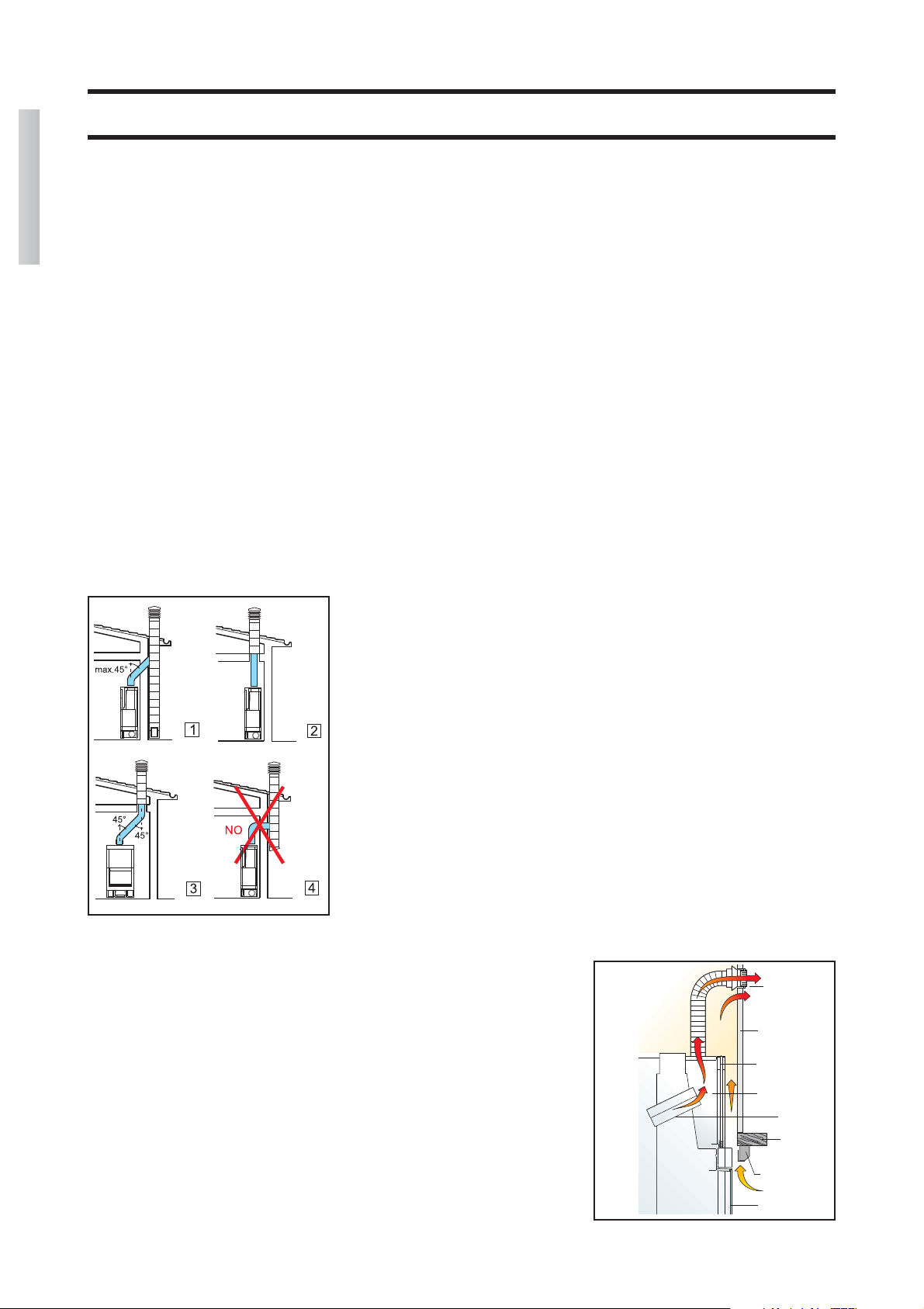
- have constant section, almost vertical
flow and not slant more than 45°
- have preferably circular internal sec-
tions; in case of rectangular sections, fig. 1
hot air flow
grille
fireplace
mantel
sliding door rails
metallic shell
hood
wooden
beam
front panel
sliding door