652324
27
Verklein
Vergroot
Pagina terug
1/56
Pagina verder
ENGLISH
100 - 150 - 200 - 250 - 300 - 350
INSTALLATION AND SERVICING INSTRUCTIONS
MODULEX EXT
2
Warning: this manual contains instructions to be used exclusively by the in-
staller and/or a competent person in accordance with the current laws in force.
The end user MUST not make any alterations to the boiler.
Failure to follow the instructions indicated in this manual, which is supplied
with the boiler, could cause injury to persons, animals or damage to property.
UNICAL shall not be held liable for any injury and/or damage.
CONTENTS
1 GENERAL INFORMATION ................................................................................................................................................................................. 3
1.1 Symbols used in this guide ........................................................................................................................................................................... 3
1.2 Correct use of the appliance .........................................................................................................................................................................3
1.3 Information to be passed over to the person in charge of the appliance ......................................................................................................3
1.4 Safety warnings ............................................................................................................................................................................................4
1.5 Standard code for installations......................................................................................................................................................................5
1.6 Installation .....................................................................................................................................................................................................5
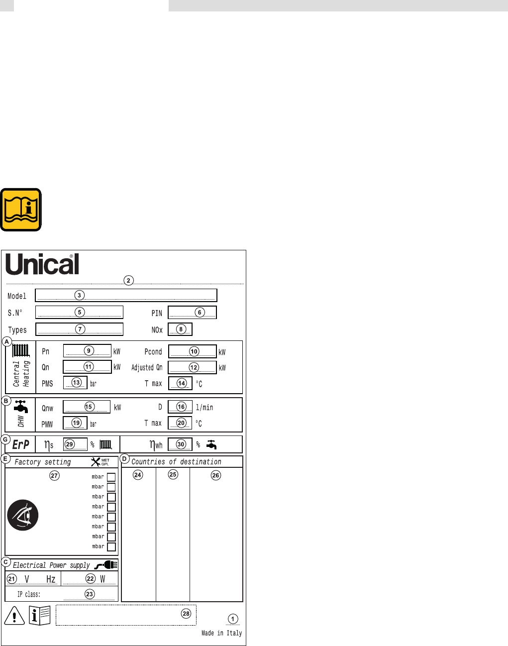
1.7 Data badge ...................................................................................................................................................................................................5
1.8 Water treatment ............................................................................................................................................................................................ 7
1.9 General warnings ..........................................................................................................................................................................................8
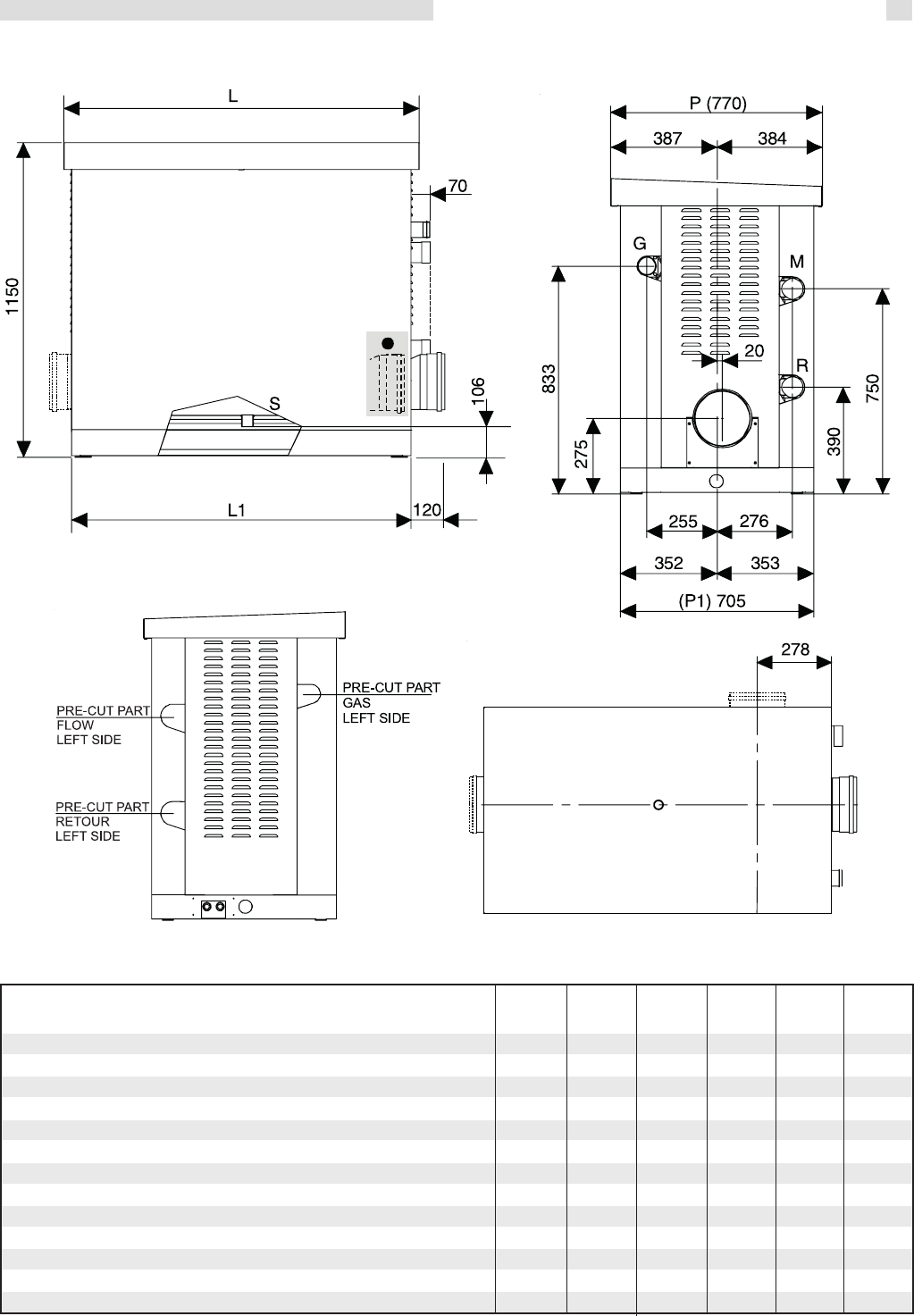
2 TECHNICAL FEATURES AND DIMENSIONS ...................................................................................................................................................9
2.1 Technical features ......................................................................................................................................................................................... 9
2.2 RHS view showing main components .........................................................................................................................................................10
2.3 Dimensions ................................................................................................................................................................................................. 11
2.4 Performance data .......................................................................................................................................................................................12
2.4.1 Performance DATA ErP ......................................................................................................................................................................13
3 INSTRUCTIONS FOR THE INSTALLER ...........................................................................................................................................................14
3.1 General warnings .......................................................................................................................................................................................14
3.2 Packaging ..................................................................................................................................................................................................15
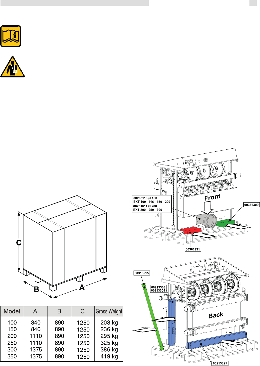
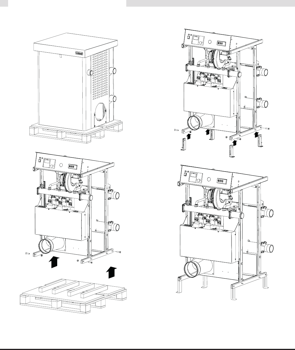
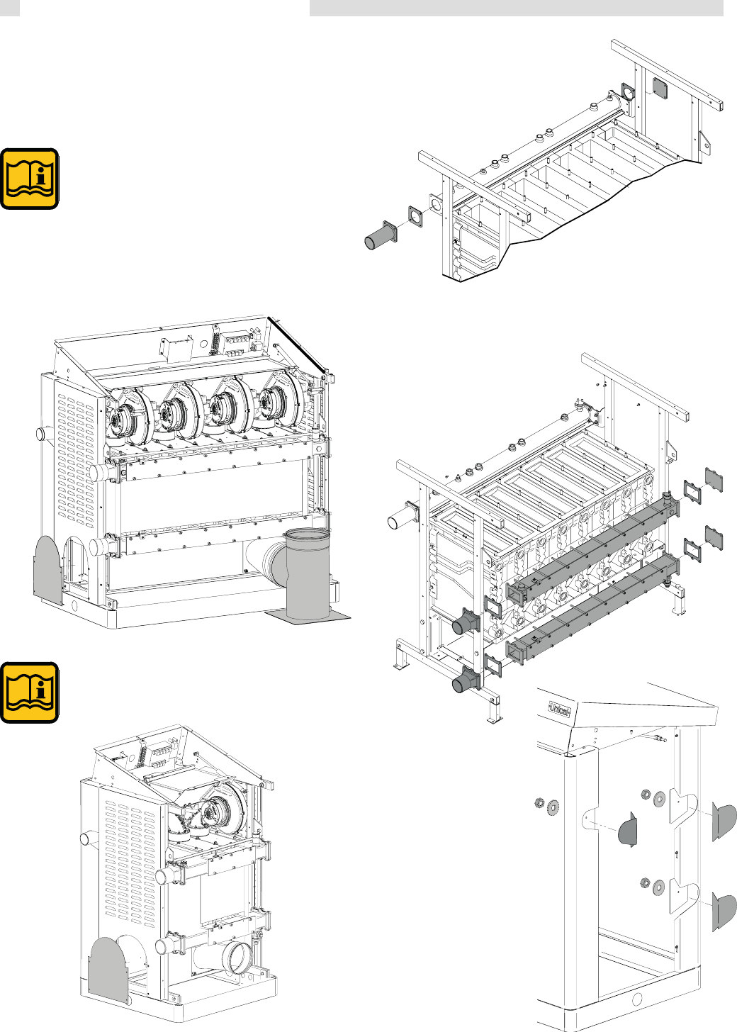
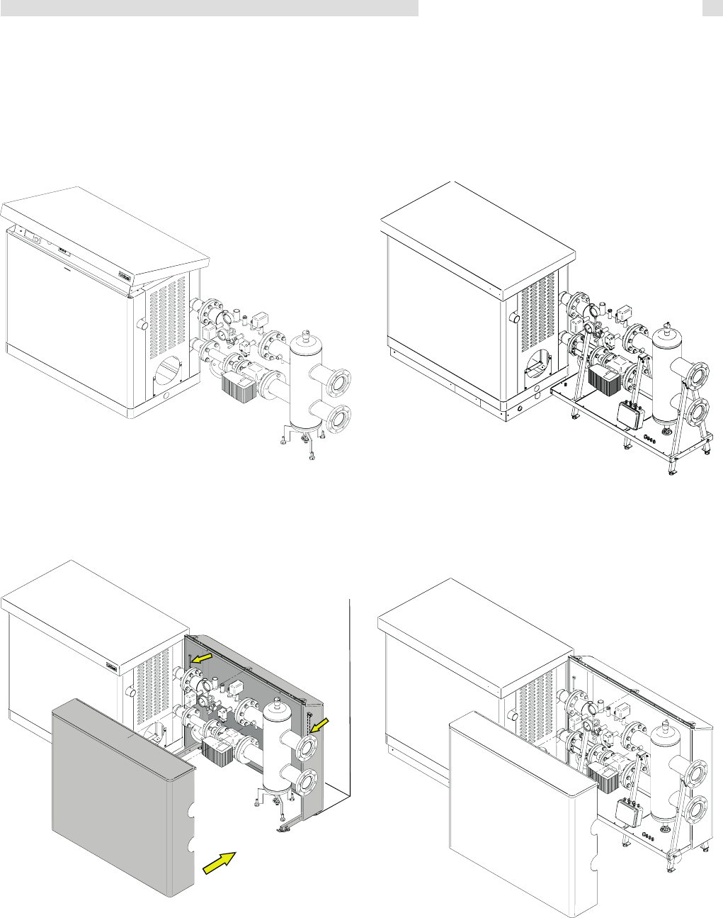
3.3 Removal from the bed and insert foot ........................................................................................................................................................16
3.4 Boiler location in a boiler room ..................................................................................................................................................................16
3.6 Boiler connection ....................................................................................................................................................................................... 18
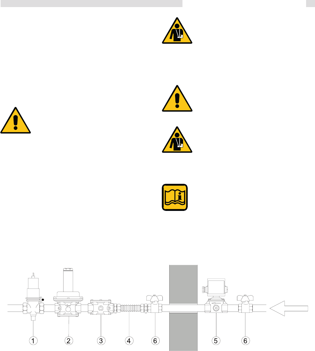
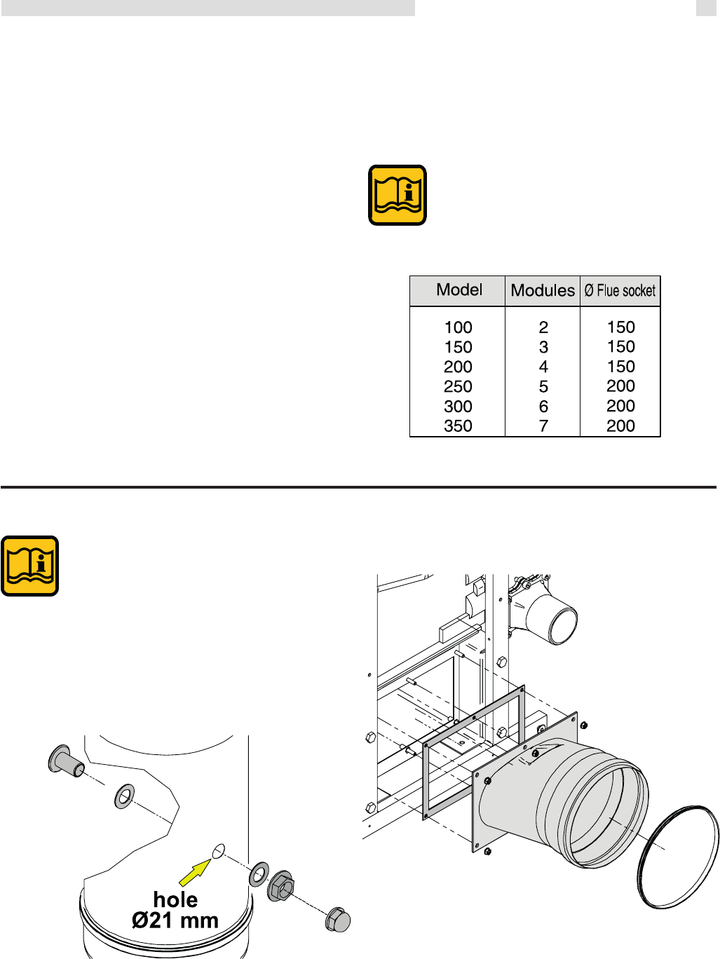
3.7 Gas connection..........................................................................................................................................................................................19
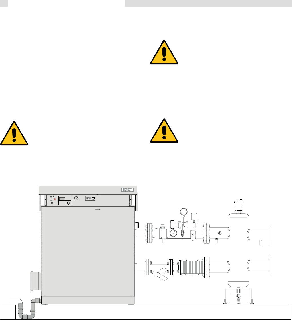
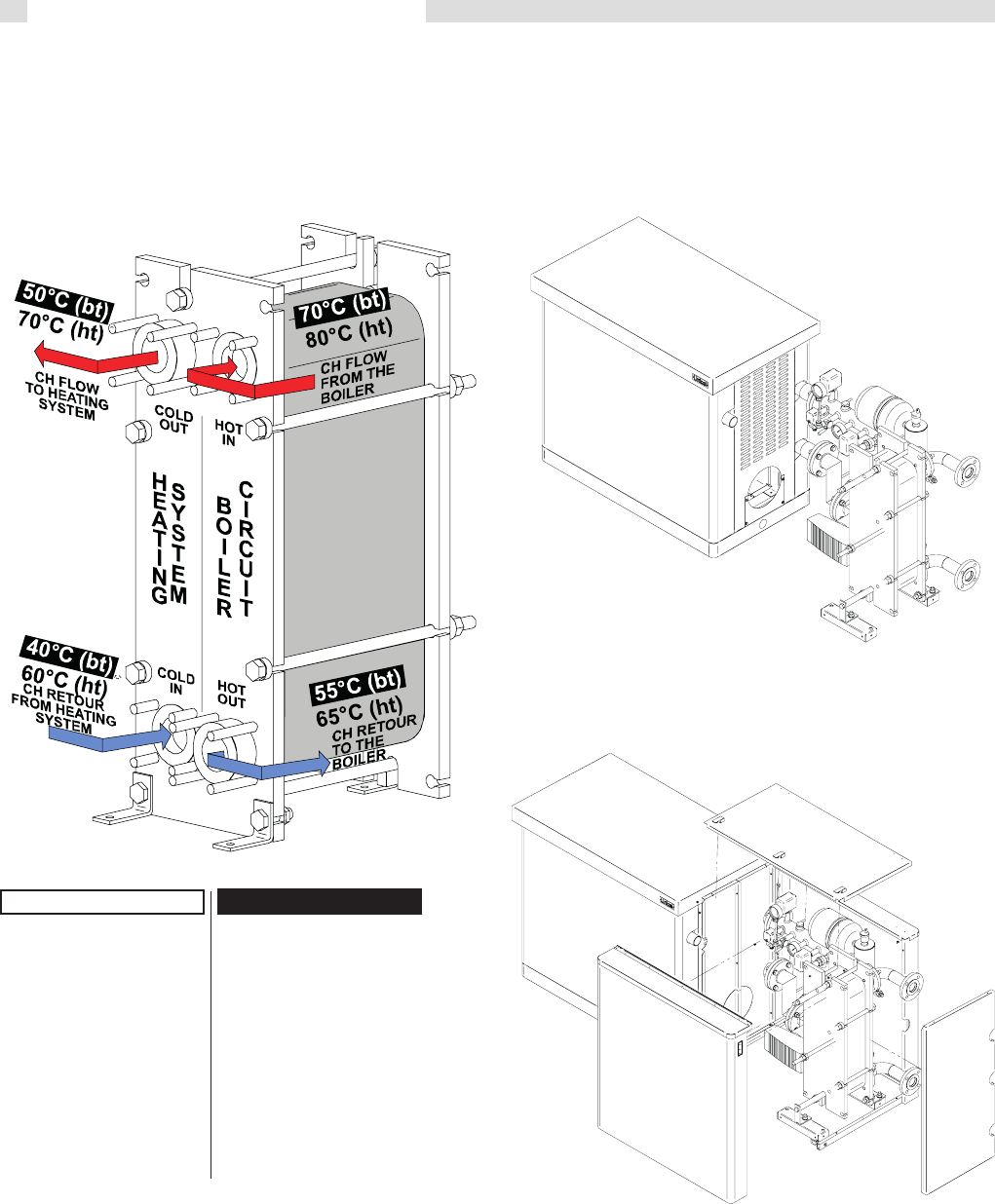
3.8 Connection return and flow system pipes..................................................................................................................................................20
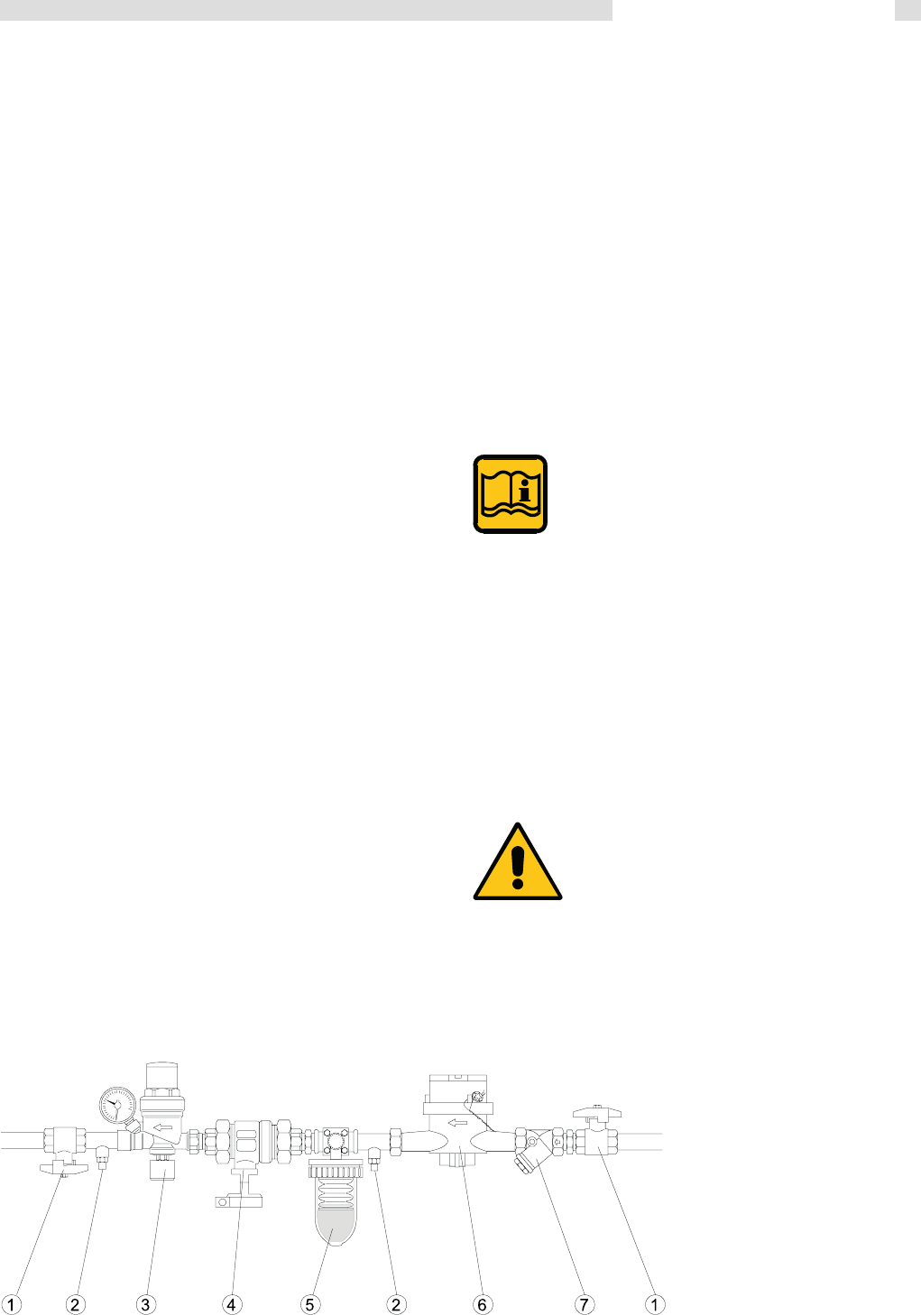
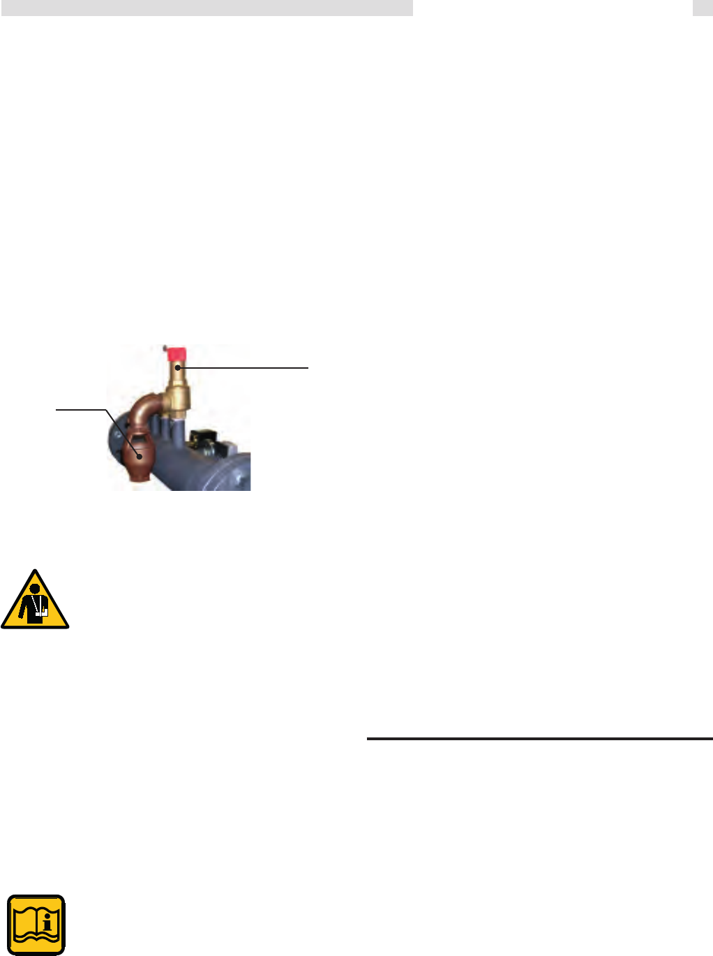
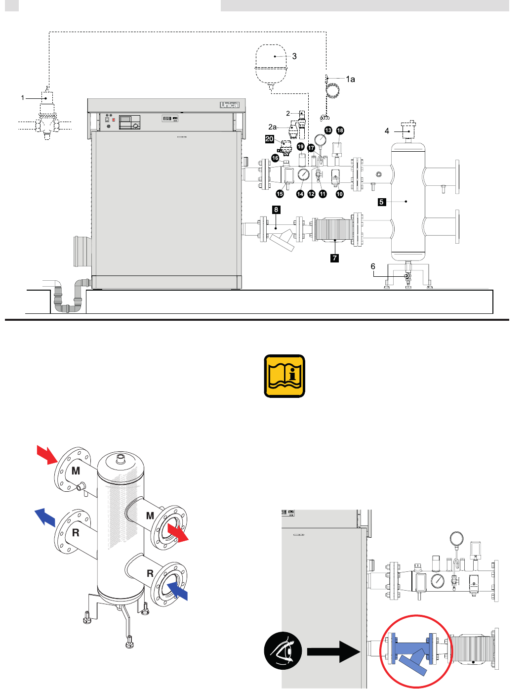
3.9 Additional safety and control devices, according to the Italian Law + primary circuit kit ...........................................................................21
3.10 Mixing header ............................................................................................................................................................................................ 22
3.11 Mixing header filter ....................................................................................................................................................................................22
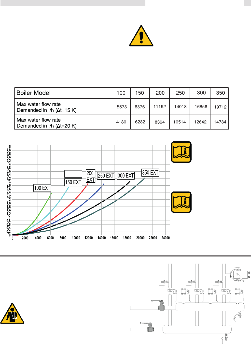
3.12 Determination of primary boiler pump or boiler system pump ...................................................................................................................23
3.13 Ballstop valves ...........................................................................................................................................................................................23
3.14 Plate heat exchanger .................................................................................................................................................................................24
3.15 Primary circuit ............................................................................................................................................................................................24
3.16 Condensing drain ......................................................................................................................................................................................26
3.17 Flue chimney connection ...........................................................................................................................................................................27
3.18 Flue mainfold connection .......................................................................................................................................................................... 27
3.19 Electrical connection .................................................................................................................................................................................29
3.20 Wiring diagram ..........................................................................................................................................................................................30
CONNECTING RING PRIMARY (SUPPLIED WITH MODULAR PUMP)................................................................................................. 31
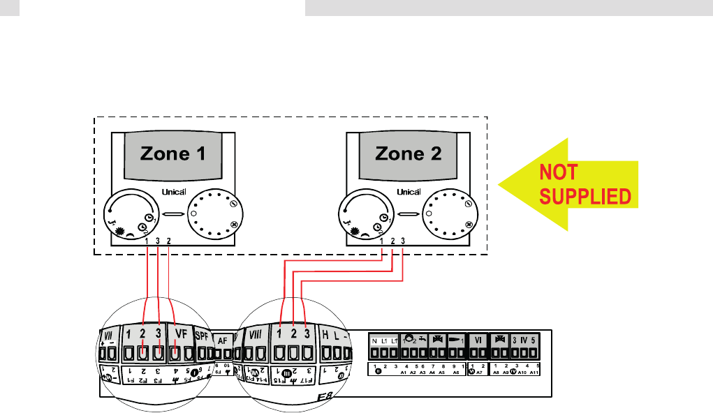
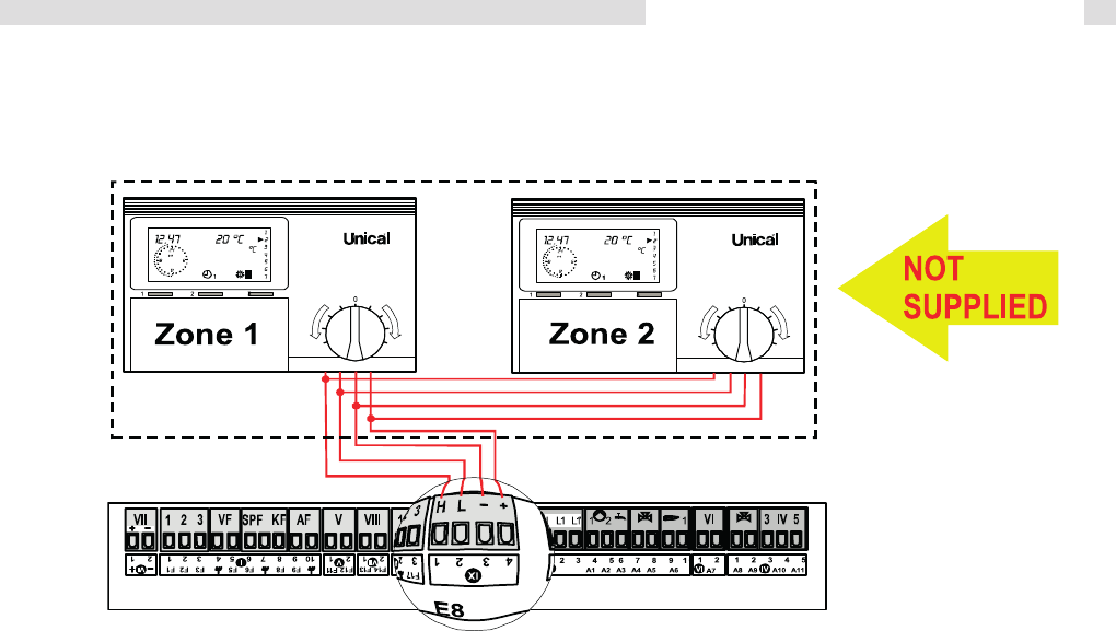
THERMOSTAT ON / OFF CONNECTIONS .............................................................................................................................................31
THERMOSTAT FBR 2 CONNECTION (room sensor) ..............................................................................................................................32
MODULATING THERMOSTAT CONNECTIONS ......................................................................................................................................33
3.21 FUNCTIONAL WIRING DIAGRAM ...........................................................................................................................................................34
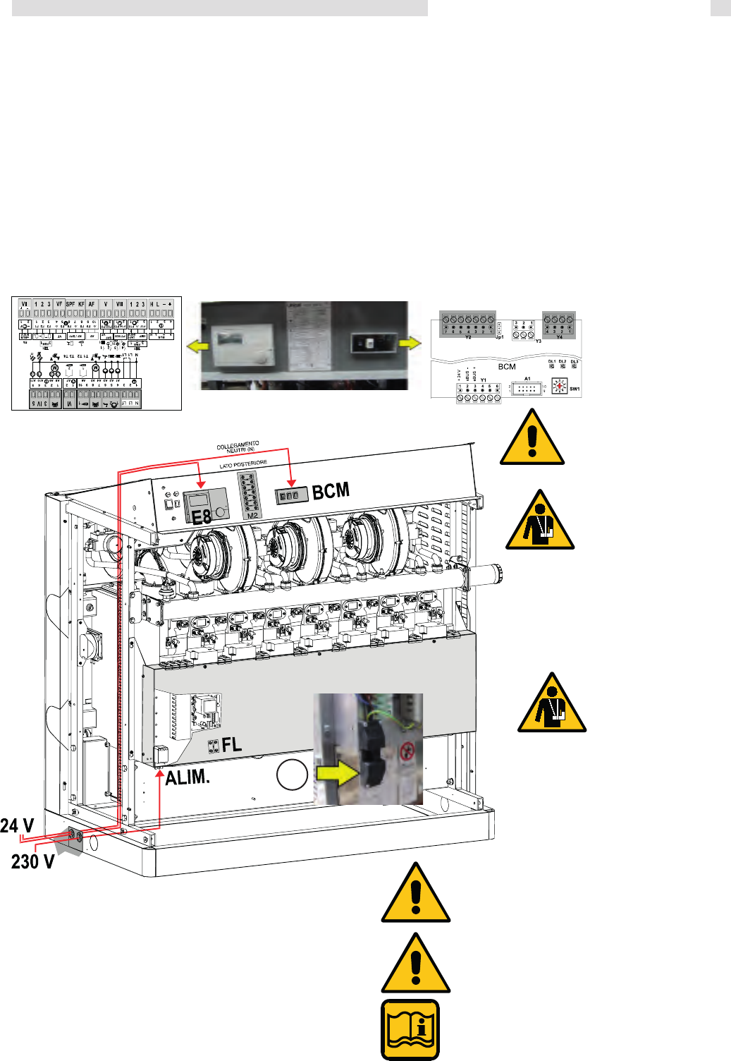
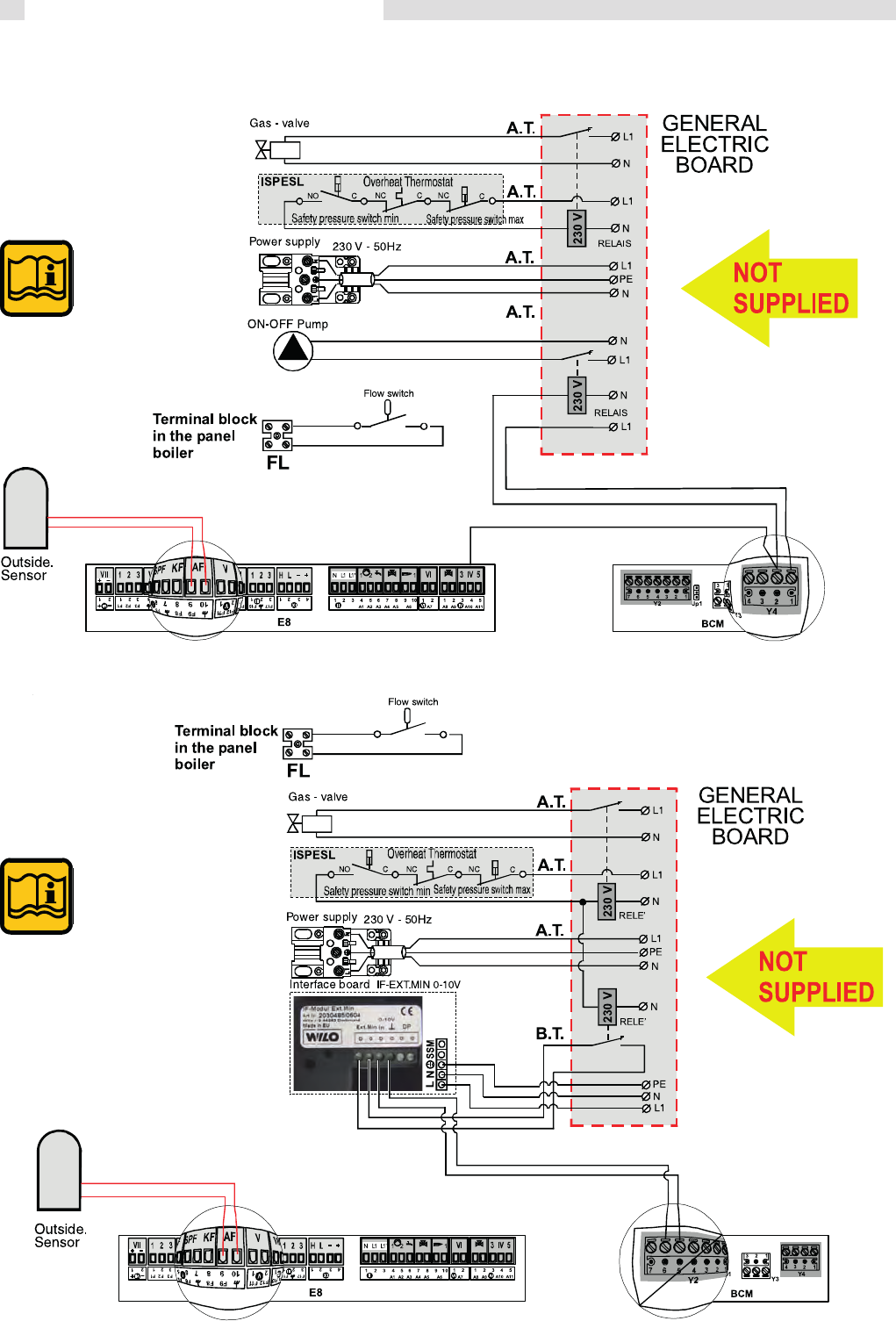
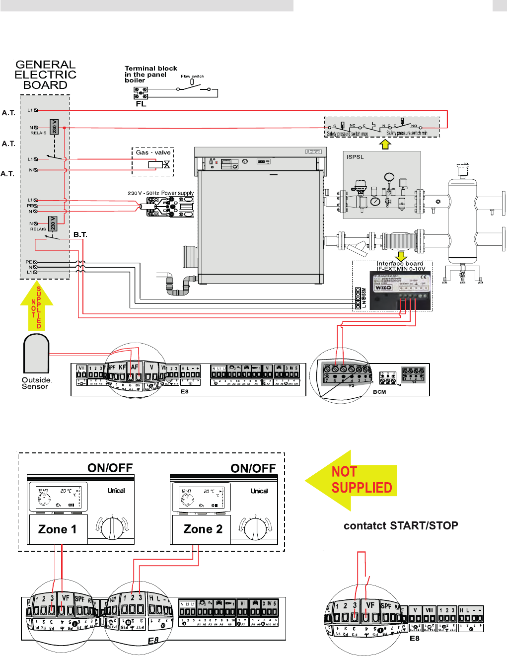
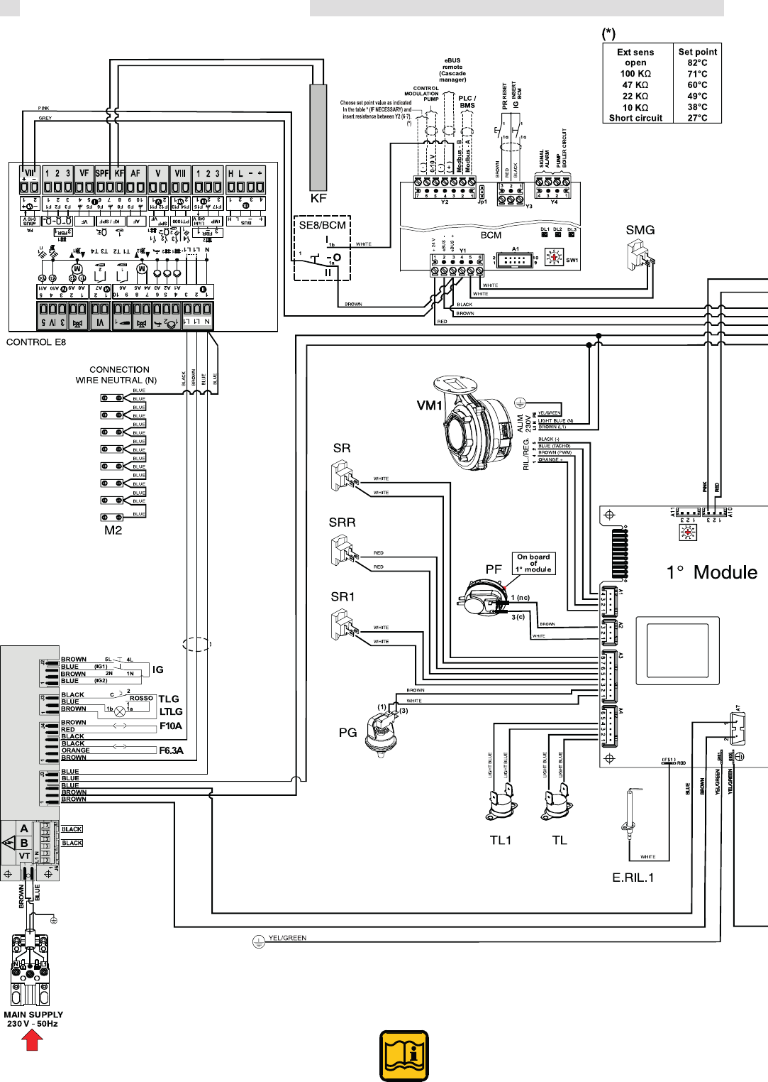
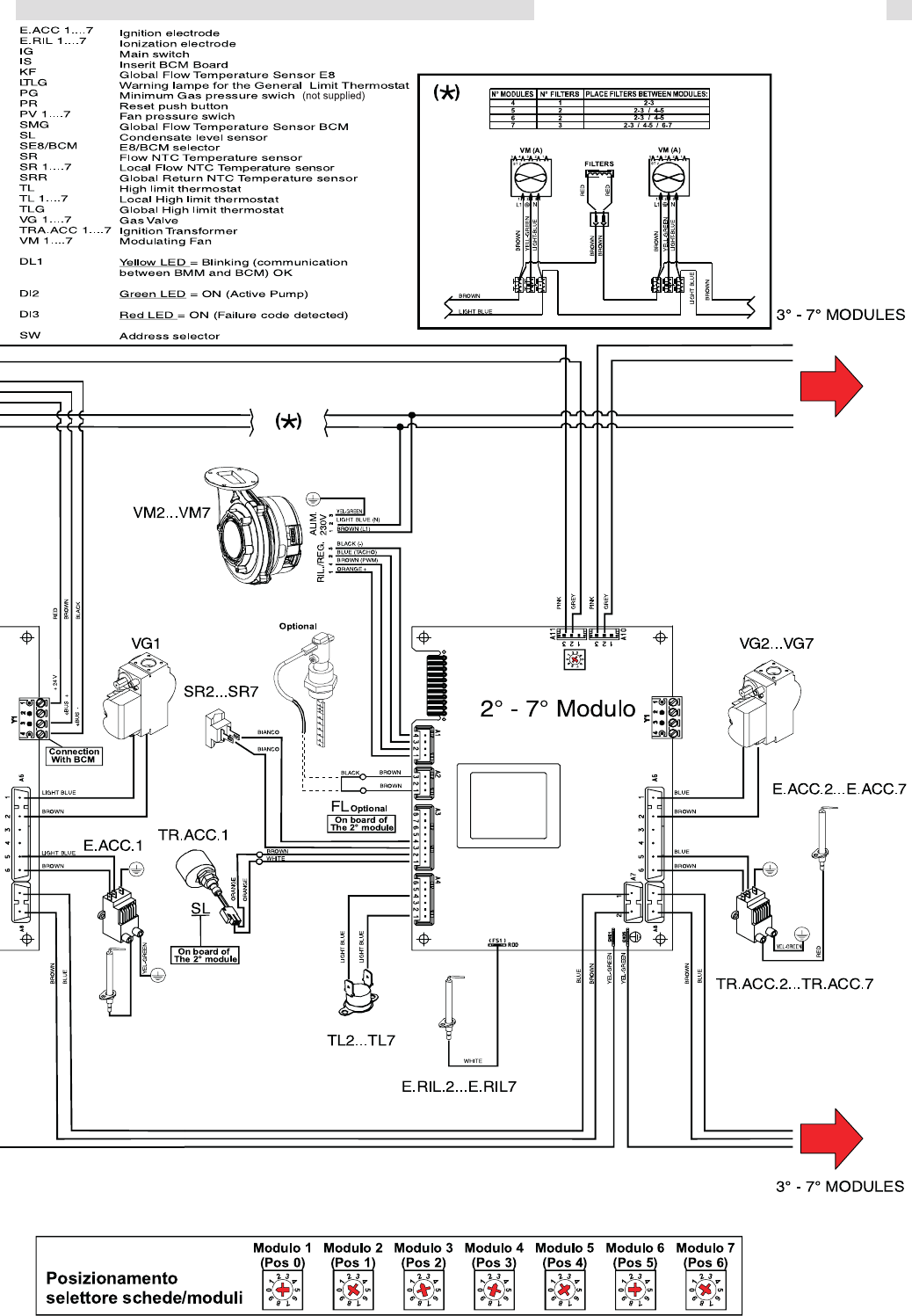
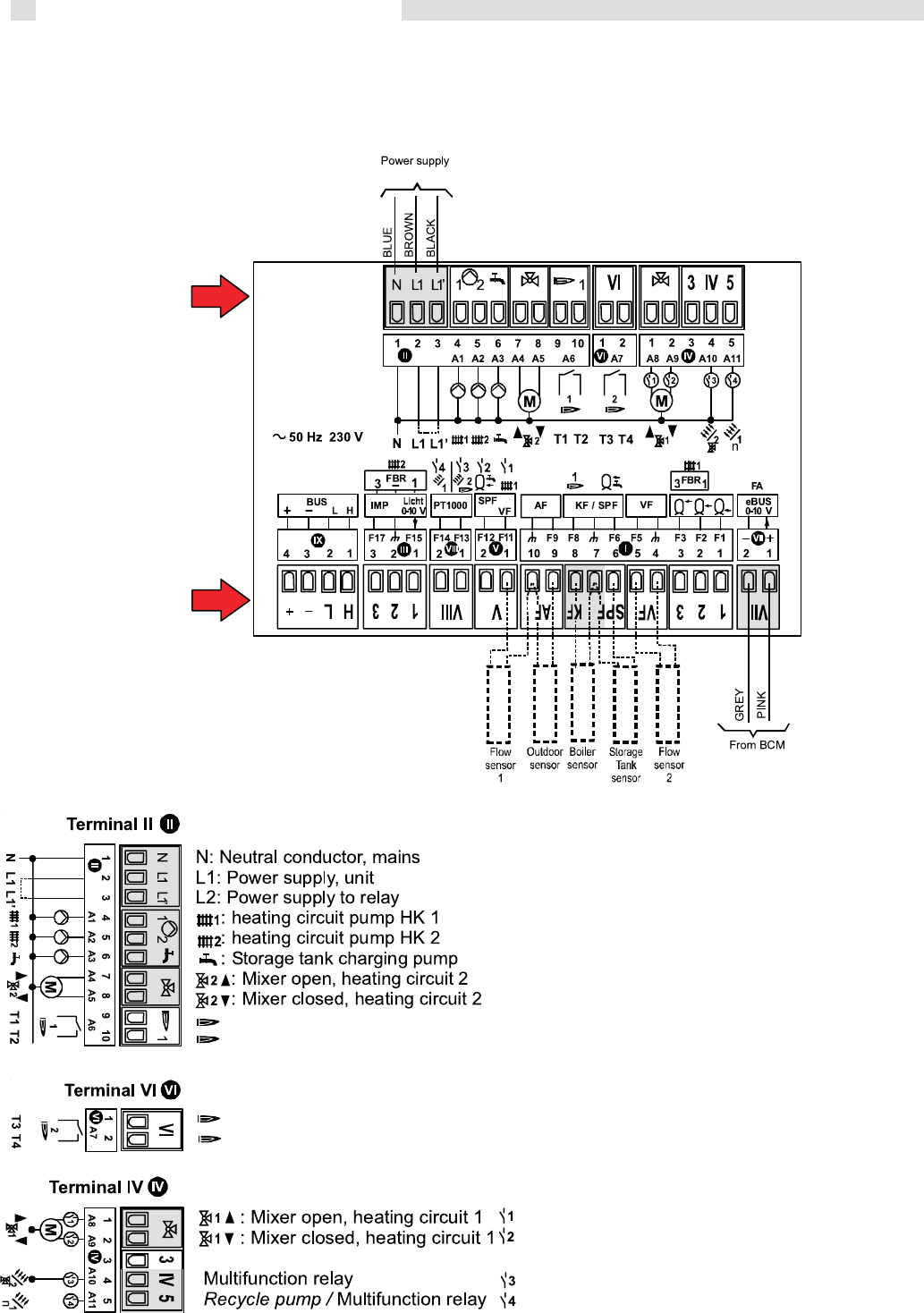
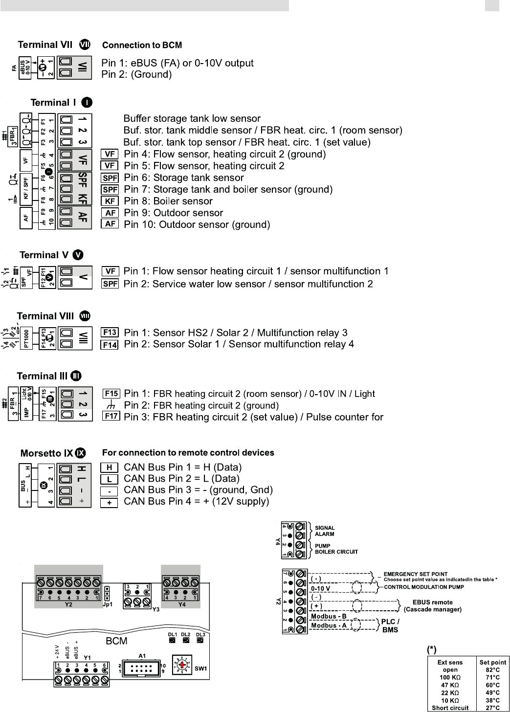
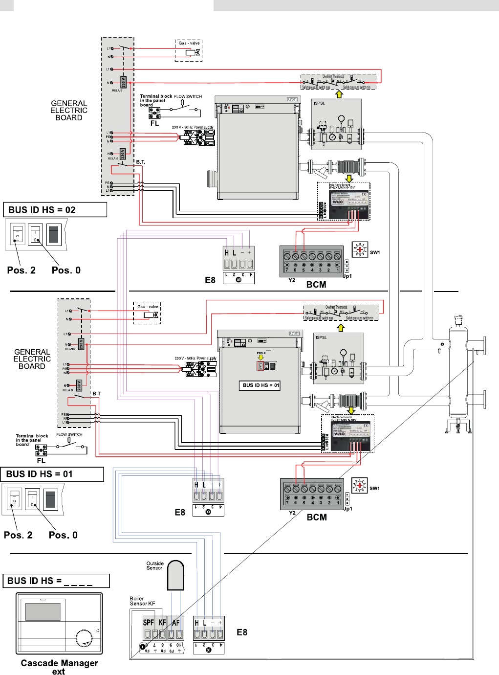
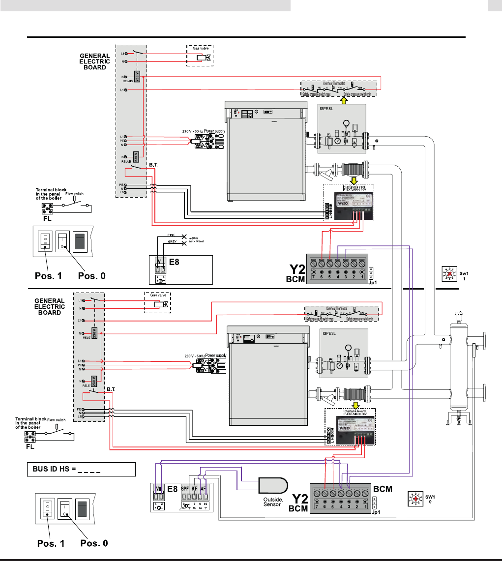
3.22 WIRING DIAGRAM FOR CONNECTIONS AND MANAGING ................................................................................................................35
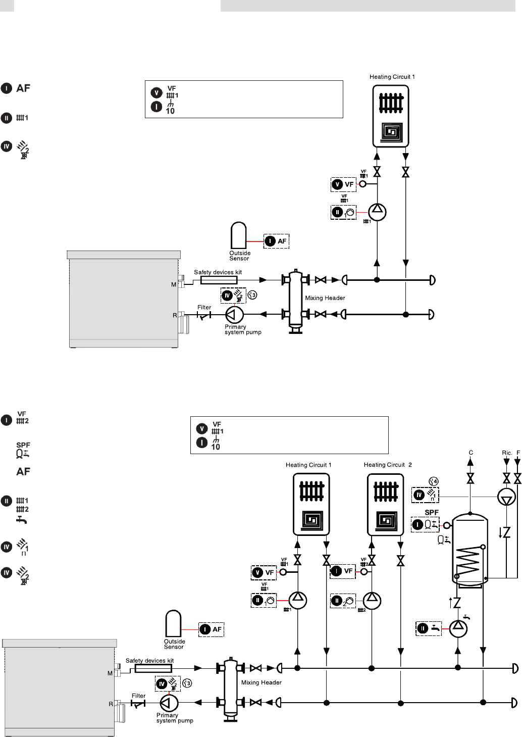
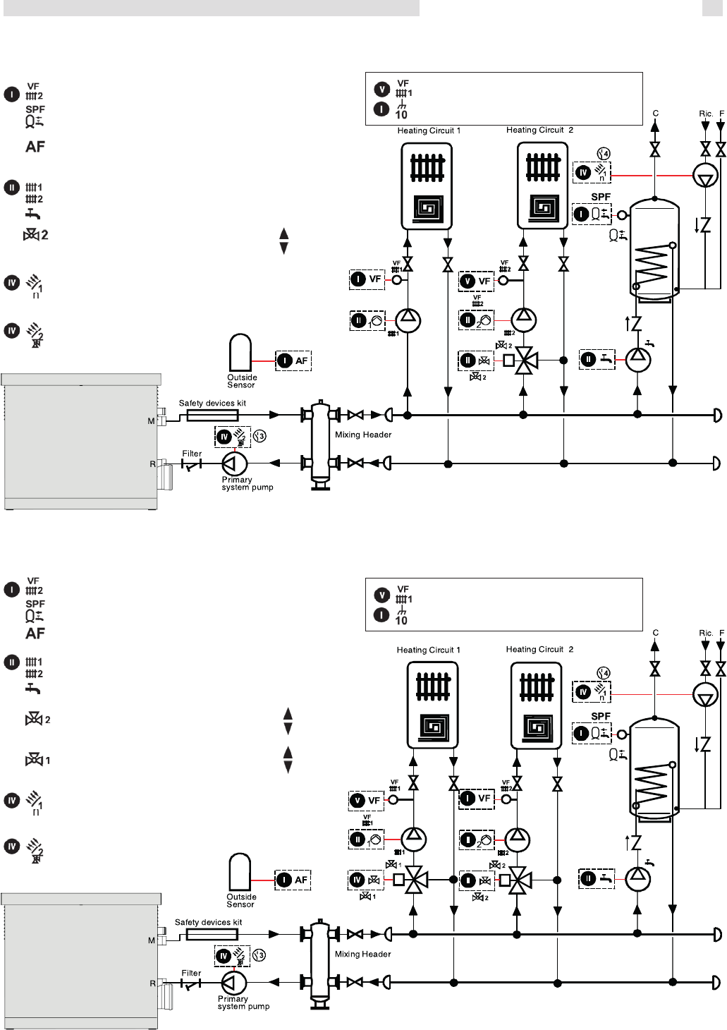
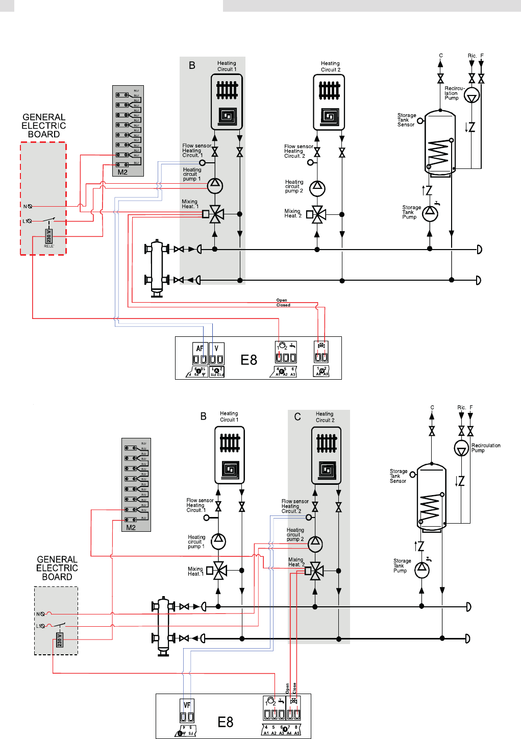
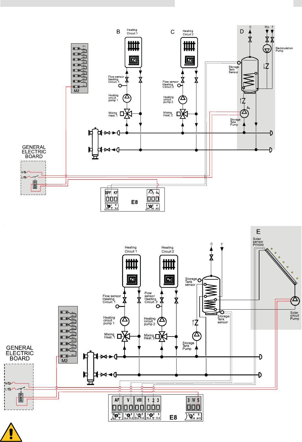
3.23 Installation examples (functional wiring and connections description) ......................................................................................................38
3.24 Cascade manager BCM ............................................................................................................................................................................43
3.25 Filling the system ....................................................................................................................................................................................... 44
3.26 Boiler Freeze protection .............................................................................................................................................................................44
3.27 Burner Adjustment .....................................................................................................................................................................................45
3.28 Emergency functions .............................................................................................................................................................................. 48
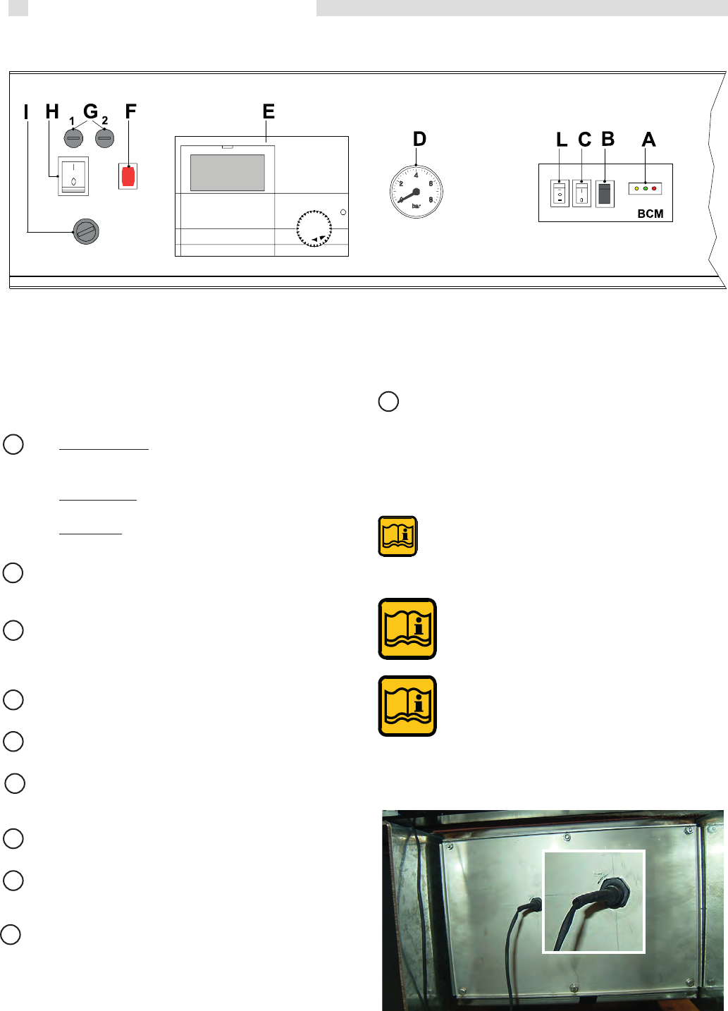
3.29 Lighting and shutting down procedures ..................................................................................................................................................... 49
4 SERVICING SCHEDULE ..................................................................................................................................................................................50
3
General Information
1.1 - SYMBOLS USED IN THIS GUIDE
When reading this guide particular care has to be given to the parts marked with the followings symbols:
1.2 - CORRECT USE OF THE APPLIANCE
The ALKON appliance has been designed utilizing today’s heating technology and in compliance with the
current safety regulations.However, following an improper use, dangers could arise for the safety and life
of the user or of other people, or damage could be caused to the appliance or other objects.The appliance
is designed to be used in pumped hot water central heating systems. Any other use of this appliance will be
considered improper. UNICAL declines any responsibility for any damages or injuries caused by an improper
use; in this case the risk is completely at the users responsibility. In order to use the appliance according
to the scopes it was designed for it is essential to carefully follow the instructions indicated in this guide.
1.3 - INFORMATION TO BE HANDED OVER TO THE USER
1
GENERAL INFORMATION
NOTE!
Suggestions for the
user
WARNING!
Indicates a potentially dangerous
situation for the product and the en-
vironment
DANGER!
Indicates serious danger
for your personal safety
and for your life
The user has to be instructed on the use and operation of his heating system, in particular:
Hand over these instructions to the end user, together with any other literature regarding this appliance,
placed inside the envelope contained in the packaging. The user has to keep these documents in a safe
place in order to always have them at hand for future reference.
Informtheuserontheimportanceofairventsandoftheueoutletsystem,stressingthefactthatisabsolutely
forbidden to make any alterations to the boiler.
Inform the user how to check the system’s water pressure as well as informing him how to restore the correct
pressure.
Explain the function of time and temperature controls, thermostats, heating controls and radiators, to ensure
the greatest possible fuel economy.
Remind the user that it is obligatory to carry out a comprehensive service annually and a combustion analysis
every two years (in compliance with the national law).
If the appliance is sold or transferred to another owner or if the present user moves home and leaves the
appliance installed, ensure yourself that the manual always follows the appliance so that it can be consulted
by the new owner and/or installer.
Failure to follow the instructions indicated in this guide, which is supplied with the boiler, could cause injury
to persons, animals or damage to property. The manufacturer shall not be held liable for any such injury
and/or damage.
4
General Information
WARNING!
The device should not be used by people with reduced physical, mental and sensory, experience and
knowledge. These people must be well-informed and supervised during the work. Children must be
supervised so they do not play with the appliance.
WARNING!
The installation, adjustment, and servicing of this appliance must be carried out by a competent person
and installed in accordance with the current standards and regulations. Failure to correctly install this
appliance could cause injury to persons, animals or damage to property. The manufacturer shall not be
held liable for any injury and/or damage.
DANGER!
Servicing or repairs of the appliance must be carried out by UNICAL authorised service technicians; UNICAL re-
commends drawing up a service contract. Bad or irregular servicing could compromise the safe operation of the
appliance, and could cause injury to persons, animals or damage to property for which UNICAL shall not be held
liable.
Modications to parts connected to the appliance
Donotcarryoutanymodicationstothefollowingparts:
- the boiler
- to the gas, air, water supply pipes and electrical current
- totheuepipe,safetyreliefvalveanditsdrainagepipe
- totheconstructivecomponentswhichinuencetheappliance’ssafeoperation
WARNING!
When tightening or loosening the screw pipe connections, use only adequate fork spanners.
The improper use and/or the use of inadequate equipment can cause damages (for example water or gas leakages).
WARNING!
Indications for appliances operating with propane gas
Ensure yourself that before installing the appliance the gas tank has been purged.
For a correct purging of the tank contact the liquid gas supplier or a competent person who has been legally authorized.
If the tank has not been correctly purged problems could occur during ignition.
If this occurs contact the liquid gas tank’s supplier.
Smell of gas
If you smell gas follow these safety indications:
- Do not turn on or off electrical switches
- Do no smoke
- Do not use the telephone
- Close the main gas tap
- Open all windows and doors where the gas leakage has occurred
- Inform the gas society or a company specialized in installing and servicing heating systems
Explosive and easily inammable substances
Donotuseorleaveexplosiveoreasilyinammablematerial(asforexample:petrol,paint,paper)intheroomwhere
the appliance has been installed.
1.4 - SAFETY WARNINGS
WARNINGS
The boiler has to be installed in such way to avoid,
under the foreseen operation conditions, the congelation of the water and
to prevent that the control devices are exposed to a temperature
lower than -15°C and higher than 40°C.
The boiler has to be protected against environmental variations with:
- The insulation of the hydraulic pipelines and the condensate evacuation
- TheadoptionofspecicantifreezeproductsintheC.H.installation.
5
General Information
When the appliance is installed on existing systems, ensure
yourself that:
- Theueoutletpipeissuitableforcondensingboilers,for
the temperature of the products of combustion, calculated
and manufactured according to the regulations in force. It
must be installed as much as possible in a straight line,
tested for soundness, insulated and must not have any
occlusions or restrictions.
- Theueoutletpipehasaconnectionforthedischargeof
condensate.
- The boiler room has a suitable outlet for the discharge of
condensate produce by the boiler.
- Theelectricalsystemhasbeenttedincompliancetothe
specicnormsandtheworkhasbeencarriedoutbya
competent person.
- Thecirculationpump’soutput,theheadandowdirection
are suitable.
- The gas feeding supply pipe and the eventual tank are
constructed according to the regulations in force.
- The expansion vessels assure the total absorption of the
dilatationoftheuidcontainedinthesystem.
- The system has been cleaned of impurities and lime scale.
When a Modulex boiler is installed onto an existing
heating system:
In case the replacement of an existing boiler in an old system can
be programmed, it
is necessary to thoroughly
clean out the system with a basic solution.
The system must be cleaned 4 weeks before
the substitution, with the system ring at a
temperature of 35°C to 40°C.
WARNING!
If it is noticed that a new Modulex has replaced,
in an old system the existing boiler without having first perfor-
med what said in the previous paragraph, Do not wash now
the system, as residual products, present in the circuit, could
lead to system gathering in the boiler body, causing damage.
UNICAL recommends contacting a specialised company for
water treatment.
Instead, if installing a Modulex boiler in a new system, it is
still recommended to thoroughly clean out the system with an
adequate product and fit a Y filter with two isolating valves onthe
boiler’s return pipe, so that, when necessary, it can be cleaned.
This filter will protect the boiler from the dirt coming from the
heating system.
When sizing pumps, it is necessary to take into consideration
the pressure losses which occurin the primary circuit.
1.6 - INSTALLATION ON EXISTING HEATING SYSTEMS
1.5 - STANDARD CODES FOR
INSTALLATION
The appliance must be installed in compliance to the instructions
contained in this manual.
Theinstallationmustbe carriedoutby acompetentqualied
engineer, whom will assume the responsibility of complying to
allthelocaland/ornationalregulationspublishedintheofcial
publications, as well as all the applicable codes of practice.
Before installing the appliance please contact the gas supply
company.
The installation must be carried in accordance to the codes of
practice, the regulations and the requirements hereby indicated
which constitute an indicative list, but not a complete one, as
these continue to undergo evolve devolpments.
Moreover, the boiler must be installed in accordance to all the
regulations regarding the boiler room, the building regulations
and the prescriptions regarding central heating plants in force
in the country where the boiler is installed.
The appliance must be installed, commissioned and serviced
according to the regulations in force. This is also valid for the
hydraulicsystem,theueoutletsystemandtheboilerlocation
room.
Failure to comply with these rules will
nullify the warranty
6
General Information
1.6 - TECHNICAL DATA PLATE
CE marking
TheCEmarkingcertiesthattheboilersmeet:
- The essential requirements of the gas appliance directive
(directive 2009/142/EEC)
- The essential requirements of the electromagnetic compat-
ibility directive (2004/108/EEC)
- Theessentialrequirementsoftheefciencydirective(92/42/
EEC)
- Theessentialrequirementsoftheefciencydirective(direc-
tive 2006/95/EEC)
The Technical data plate is placed
under the casing over the forehead
stirrup.
KEY:
1 = CE monitoring body
2 = Type of boiler
3 = Boiler model
4 = Number of stars (directive 92/42 EEC)
5 = (S.N°) Serial Number
6 = P.I.N.ProductIdenticationNumber
7 = Typesofapproveduegasexhaustcongurations
8 = (NOx)NOxClass
A = Heatingcircuitcharacteristics
9 = (Pn) Effective nominal output
10 = (Pcond) Effective output in condensation
11= (Qn)Maximumheatoutput
12= (AdjustedQn)Adjustedforratedheatoutput
13= (PMS)Max.heatingoperatingpressure
14= (Tmax)Max.heatingtemperature
B = Domestichotwatercircuitcharacteristics
15= (Qnw)Ratedheatoutputindomestichotwaterfunction
(if different to Qn)
16= (D)SpecicD.H.W.owrateaccordingtoEN625-EN
13203-1
19= (PMW)Max.domestichotwateroperatingpressure
20= (Tmax)Max.domestichotwatertemperature
C = Electricalcharacteristics
21= Electricalpowersupply
22 = Consumption
23 = Protection rating
D = Countries of destination
24 = Direct and indirect countries of destination
25 = Gas category
26 = Supply pressure
E = Factory settings
27 = Adjusted for gas type X
28 = Space for national brands
G = ErP
29=Seasonalspaceheatingenergyefciency
30 =EnergyefciencyinDHWproductionmode
7
General Information
1.8 - WATER TREATMENT
The chemical-physical characteristics of the filling water and
reinstatement water in heating systems are of fundamental
importance for guaranteeing correct and safe boiler operation.
Before filling the CH circuit with water, it is necessary to analyse
the water and decide for a proper treatment.
The purpose of this treatment is finalized to eliminate or sub-
stantially reduce the following problems:
- lime scale deposit
- corrosions
- deposits
- biological growths (moulds, bacteria, algae, fungi, etc)
The chemical treatment of the network water enables the
prevention of these problems and guarantees safe boiler
operation and economical advantages, in terms of mainte-
nance and global thermal efficiency.
The chemical analysis of the water enables us to obtain a lot
of information on the system’s condition and state of “health”.
It is essential to avoid any problems with the boiler.
The pH is a measure of the acidity or alkalinity of a solution.
The pH scale has a range of 0-14, where 7 is neutral.
Values inferior to 7 indicate acidity, values above 7 indicate
alkalinity.
The ideal pH value for water in heating systems fitted with
aluminium boilers is between 6,5 and 8, with a hardness
of 15°F.
In heating systems where the water has a value outside this ran-
ge, this considerably accelerates the destruction of the protective
oxidized layer which naturally develops inside the aluminium
bodies: if the pH is below 6, acidity is present, if it is above 8,
the water is alkaline or it is caused by an alkaline treatment (for
example phosphate or glycol used as an antifreeze) or in several
cases it is due to the natural formation of alkaline in the system.
Vice versa, if the pH value is between 6,5 and 8, the aluminium
surfaces of the boiler body are passivated and protected from
further corrosive attacks.
To minimize corrosion it is essential to use a scale inhibitor,
however in order for this to function correctly, the metallic
surfaces have to be clean.
The best corrosion inhibitors on sale also contain a pro-
tective system for aluminium which acts by stabilizing the
water’s pH value, preventing unforeseen variations.
We recommend that the heating system’s water pH value is
systematically controlled (minimum twice a year). In order
to do this, it is not necessary to run a chemical analysis in a
laboratory, but it is sufficient to use a simple analytical ‘kit’
contained in portable cases, easily found on sale.
Therefore, prior to filling the heating system with water it will be
necessary to fit the devices indicated in the figure below.
THE CONNECTION MUST BE FITTED ON THE
PRIMARY CIRCUIT’S RETURN PIPE DOWN-
STREAM OF THE CIRCULATING PUMP
All the necessary precautions must be taken in order to avoid
the formation and localization of oxygen in the system’s water.
For this reason, the plastic pipes used in underfloor heating
systems must be impermeable to oxygen.
If any antifreeze solutions are used ensure yourself that they are
compatible with aluminium and with any other components and
materials fitted on the system.
WARNING!
ANY DAMAGE CAUSED BY THE BOILER,
DUE TO THE FORMATION OF LIME SCALE
OR DUE TO CORROSIVE WATER WILL INVA-
LIDATE THE APPLIANCE WARRANTY.
1. Ball valve
2. Inspection pocket
3. Filling-up group
4. Disconnector
5. Scale reducing device
6. Litrecounter
(recommended)
7. “Y” filter
EXAMPLE OF SCALE REDUCING DEVICE CONNECTION FOR WATER TREATMENT
8
General Information
1.9 - GENERAL WARNINGS
This instruction manual is an integral and indispensable part
of the product and must be retained by the person in charge of
the appliance.
Please read carefully the instructions contained in this manual as
they provide important indications regarding the safe installation,
use and servicing of this appliance.
Keep this manual in a safe place for future reference.
The installation and servicing must be carried out in ac-
cordance with the regulations in force according to the
manufacturers instructions and by legally competent
authorized persons.
By a competent person, we imply a person who has a spe-
cic technical qualication in the eld of components for
central heating systems for domestic use, domestic hot
water production and servicing. The person must have the
qualications foreseen by the current laws in force.
Bad or irregular servicing could compromise the safe operation
of the appliance, and could cause injury to persons, animals or
damage to property. The manufacturer shall not be held liable
for any such injury and/or damage.
Before carrying out any cleaning or servicing turn off the electrical
supply to the boiler by means of the ON/OFF switch and/or by
means of the appropriate shutdown devices.
Do not obstruct the intake/outlet terminal ducts.
In the event of failure and/or faulty functioning of the appliance,
switch off the boiler. Do not attempt to make any repairs: contact
qualiedtechnicians.
Any repairs must be carried out by Unical authorized technicians
and using only original spare parts. Non-observance of the above
requirement may jeopardize the safety of the appliance.
Toguaranteetheefciencyandcorrectfunctioningoftheap-
pliance it is indispensable to have the boiler serviced annually
byaqualiedperson.
If the boiler remains unused for long periods, ensure that any
dangerous parts are rendered innocuous.
If the appliance is sold or transferred to another owner or if the
present user moves home and leaves the appliance installed,
ensure yourself that the manual always follows the appliance
so that it can be consulted by the new owner and/or installer.
Only original accessories must be used for all appliances sup-
plied with optionals or kits (including electrical ones).
This appliance must be used only for the purposes for which it
has been expressively designed. Any other use shall be consi-
dered incorrect and therefore dangerous (*).
9
Technical features and dimensions
TECHNICAL FEATURES
AND DIMENSIONS
2.1 - TECHNICAL FEATURES
• MODULEX is a compact, gas fired, Low NO
x
, condensing
boiler.
• made up by one sectional boiler body, suitable for a single
boiler working or directly as cascade
• Placeevenoutside(IPX5D)
• Low water content
• Fast response to load variations
• Flue terminal positionable on 3 sides
• Manifold unified delivery and return (everseble in simple way
p.16)
• Made up of two or more heating elements (2 to 7), cast alu-
minum / silicon / magnesium
• Modulating premix burners total radiation
• Each heating element without hydraulic interceptions
• One gas supply pipe (reversible)
• Modular power from 12 to 50 kW / element
TEMPERATURE CONTROL DEVICES:
• LOCALNTCsensor(eachheatingelement)
• Limitthermostatroom(eachheatingelement)
• flow NTC sensor (General)
• NTC sensor return (General)
• Safety thermostat approved (Order and install on ISPESL
device see page 18)
• FlowsensorBCM
Other safety devices (RACCOLTA R) see 3.6 pag. 18
Control panel (POP-UP) includes:
• ON-OFFswitchseepag.47
• Temperature control / boiler operator E8
• BCM(BoIIerCascadeManager)
• Fuses
• Limitthermostat>(over)350kW
• Airpressurefans
• Condensatelevelsensor
• Gaspressostat
• Smokepressostat(anti-obstruction)
• The whole group has heat sensors NTC control global tem-
perature on the flow and return..
Integral insulation with synthetic wool hypoallergenic
• Total premix burner, modulating burner with a “metal sponge”,
ad irraggiamento. Premixing into the fan. Automatic diafra-
ghm backflow of separation from the combustion chamber.
• Noise at maximum power of less than 49 dBA.
• Heatingoperation:determinationofinstantaneouspower
microprocessor control, with preset parameters for compa-
rison between temperature (or calculated from the external
temperatureregulation)andglobaltemperatureow.
• Operationmodes:
Ability to control power of the individual heating elements for
any calibration and / or assistance with access code confi-
dential.
Production of A.C.S. by NTC of priorities for control by
boiler feed pump or by three-way diverter valve controller
E8 included.
• Abilitytocontrolpoweroftheindividualheatingelements
• Controlofheatdemand:setpointtemperatureandlevelof
modulation.
2
• Monitoringofoperatingstatusandtemperature.
• Reportingofalarms.
• Settingparameters.
• Relaycontrolfortheactivationofaxedspeedpump
• Analogoutput0to10Vtocontrolamodulatingpump.
• Operationofemergencypreventsthedetentionfacilityasa
result of the interruption of communication with the control
system or any remote control unit:
• Withthepossibilityoftemperatureselectionthroughemer-
gencyresistorssuppliedwith“constantSetpoint:70°C,max
50%.
• Alarmmanagement
• Alarmresetinput.
• Relaywarningalarm.
• condensatecollectortankwithsiphonstainlesssteel
• Panelscompletewitheasilyremovablestainlesssteelpanels
paintedwithreadaptedforoutdoorinstallation
• condensatecollectiontankwithdraintrapandsmokechamber
in stainless steel.
• Built-inairvent
The application of heat can be generated by the Regolation / E8
operator or alternatively from BCM (boyler Cascade Manager)
The management logic provides the maximum number of
simultaneous operation of heating elements as possible in
order to maximize your productivity. As we provide high ex-
change surface as a function of output power. The items are
made to work so as to share equitably the operating time.
The hot water produced by the pump is pushed on the return
oftheringtotheprimaryowofthehydraulicseparator.From
here a second pump (system - see the diagrams suggested) will
arrange for the distribution to various users. The return chilled
water plant is sucked by the pump on the return through the
hydraulic separator to resume the cycle via the generator.
10
Technical features and dimensions
2.2 - R.H. SIDE VIEW, WITH MAIN COMPONENTS
Should a positioning of the ue connection be necessary on the left hand side of the boiler (the standard
is on the right) so please move the cover ‘A“ with each wiring connection, condensate level sensor, red
pressostat pipe on the rear side of the boiler. The rear side cover (just re-moved) has to be re-placed on the
right side of the boiler.
- Smoke and condensate evacuation connection on the R.H. side (forniture condition), L.H. side, BACK SIDE
order special BACK Flue kit
MODULEX EXT 100 - 116 - 150 - 200 : 00362154
MODULEX EXT 250 - 300 - 350 : 00362076
- C.H. flow connection on the R.H. side (forniture condition), L.H. side
- C.H. return connection on the R.H. side (forniture condition), L.H. side
- Gas connection on the R.H. side (forniture condition), L.H. side
11
Technical features and dimensions
FRONT VIEW
RIGHT HAND SIDE VIEW
(Delivery condition for R.H. side connection)
UPPER VIEW
MODULEX
Dimension
No. of Modules
Height mm
Width ‘’L mm
Width ‘’L1’ mm
Depth ‘’P’ mm
Depth ‘’P1’ mm
Connections
Gas mm (inch)
C.H. system Flow M mm (inch)
C.H. system Return R mm (inch)
Chimney connection ‘’D’ mm
Condensate drain diameter mm
LEFT HAND SIDE VIEW
M CH flow system
R CH safety system return
2.3 - DIMENSIONS
G Gas inlet
S Outlet condensate drain
150
3
1150
764
706
770
705
50(2 )
64 (2½)
64 (2½)
150
40
200
4
1150
1032
974
770
705
50(2 )
64 (2½)
64 (2½)
150
40
250
5
1150
1032
974
770
705
50(2 )
64 (2½)
64 (2½)
200
40
300
6
1150
1300
1242
770
705
50(2 )
64 (2½)
64 (2½)
200
40
350
7
1150
1300
1242
770
705
50(2 )
64 (2½)
64 (2½)
200
40
100
2
1150
764
706
770
705
50(2 )
64 (2½)
64 (2½)
150
40
(•) ModulexEXT100-200-300 Flueterminal
into the casing
12
Technical features and dimensions
2.4 - PERFORMANCE DATA
Fortheadjustmentdata:NOZZLES-PRESSURE-DIAGRAMS-FLOWRATESrefertotheparagraphADAPTATIONTOOTHER
TYPESOFGAS.
MODULEX EXT100 EXT150 EXT200 EXT250 EXT300 EXT350
Boiler category II
2H3P
II
2H3P
II
2H3P
II
2H3P
II
2H3P
Modulation ratio 1:8,3 1:12,5 1:16,7 1:20,8 1:25 1:29
Rated heat output on P.C.I. Qn kW 100 150 200 250 300 348
Minimum heat output on P.C.I. Qmin kW 12 12 12 12 12 12
Rated useful power (Tr 60 / Tm 80 °C) Pn kW 97,2 146,1 195,2 244,5 294 341,7
Minimum useful power (Tr 60 / Tm 80 °C) Pn min kW 11,7 11,7 11,7 11,7 11,7 11,7
Rated useful power (Tr 30 / Tm 50 °C) Pcond kW 100,1 150 200,4 251,3 302,7 354,6
Minimum useful power (Tr 30 / Tm 50 °C) Pcond min kW 12,8 12,8 12,8 12,8 12,8 12,8
Rated power performance (Tr 60 / Tm 80°C) % 97,2 97,4 97,6 97,8 98,0 98,2
Minimum power performance (Tr 60 / Tm 80°C) % 97,16 97,16 97,16 97,16 97,16 97,16
Rated power performance (Tr 30 / Tm 50°C) % 100,1 100,0 100,2 100,5 100,9 101,9
Minimum power performance (Tr 30 / Tm 50°C) % 106,5 106,5 106,5 106,5 106,5 106,5
Performance at 30% of the load (Tr 30°C) 107,3 107,3 107,3 107,3 107,3 107,3
Combustionefciencyatnominalload % 97,8 97,8 97,8 98,0 98,1 98,3
Combustionefciencywithreducedload % 98,3 98,3 98,3 98,3 98,3 98,3
Casing heat loss with burner operating (Qmin) % 1,2 1,2 1,2 1,2 1,2 1,2
Casing heat loss with burner operating (Qn) % 0,6 0,4 0,2 0,2 0,1 0,1
Netuegastemperaturetf-ta(min)(**) °C 33,4 33,4 33,4 33,4 33,4 33,4
Netuegastemperaturetf-ta(max)(**) °C 44,2 45,1 46,5 47,3 48,2 49,1
Maximum permitted temperature °C 100 100 100 100 100 100
Maximum operating temperature °C 85 85 85 85 85 85
Fluegasmassowrate(min) kg/h 19,6 19,6 19,6 19,6 19,6 19,6
Fluegasmassowrate(max) kg/h 163 245 327 409 490 569
Excess air % 25,5 25,5 25,5 25,5 25,5 25,5
Heat loss at chimney with burner on (min) % 1,7 1,7 1,7 1,7 1,7 1,7
Heat loss at chimney with burner on (max) % 2,2 2,2 2,2 2,2 1,9 1,7
Minimum heating circuit pressure bar 0,5 0,5 0,5 0,5 0,5 0,5
Maximum heating circuit pressure bar 6 6 6 6 6 6
Water content l 10,1 14,2 18,3 22,4 26,5 30,6
MethanegasconsumptionG20(pow.sup.20mbar)atQn m
3
/h 10,6 15,9 21,1 26,4 31,7 36,8
MethanegasconsumptionG20(pow.sup.20mbar)atQmin m
3
/h 1,3 1,3 1,3 1,3 1,3 1,3
GasconsumptionG25(pow.sup.20/25mbar)atQn m
3
/h 12,3 18,4 24,6 36,7 36,9 42,8
GasconsumptionG25(pow.sup.20/25mbar)atQmin m
3
/h 1,5 1,5 1,5 1,5 1,5 1,5
Propanegasconsumption(pow.sup.37/50mbar)atQn kg/h 7,8 11,6 15,5 19,4 23,3 27
Propanegasconsumption(pow.sup.37/50mbar)atQmin kg/h 0,9 0,9 0,9 0,9 0,9 0,9
Chimney base maximum pressure available Pa 100 100 100 100 100 100
Max condensate production kg/h 15,3 23 30,6 38,3 45,9 53,6
Emissions
CO at maximum heat output with 0% of O2 mg/kWh 83 83 83 83 83 83
NOx at maximum heat output with 0% of O2 mg/kWh 77 77 77 77 77 77
NOx Class 5 5 5 5 5 5
Electrical data
Power supply voltage/frequency V/Hz 230 / 50 230 / 50 230 / 50 230 / 50 230 / 50 230 / 50
Fuse on the power supply A (R) 6,3 / 10 6,3 / 10 6,3 / 10 6,3 / 10 6,3 / 10 6,3 / 10
(**) Protection rating IP X5D X5D X5D X5D X5D X5D
Room Temperature = 20°C
(*)Temperaturedetectedwithapplianceoperationowrate80°C/ret.60°C
CO
2
(min/max) See table ‘’NOZZLES - PRESSURE’’
Seasonalspaceheatingenergy2009/125CEE(<=400Kw)ηs-seeErPtable
Stand-byheatloss∆T30°C-Pstb-seeErPtable
Consumption in stand-by - Psb - see ErP table
(**) The protection IP is obtained with cap down
13
Instructions for the installer
2.4.1 - PERFORMANCE DATA ErP DIRECTIVE
MODULEX
EXT100 EXT150 EXT200 EXT250 EXT300 EXT350
Element Symbol Unit
Effective nominal output Pnominale kW 97 146 195 244 294 342
Seasonalenergyefciencytoheat
the room
ƞ
s % 92 92 92 92 92 92
Season efciency class to
discharge
A A A A A A
For boilers to heat the room
and mixed boilers: useful heat output
Useful heat output with
high temperature capacity
(Tr 60 °C / Tm 80 °C)
P
4 kW 97,2 146,1 195,2 244,5 294,0 341,7
Ratedheatoutputefciency
with high temperature capacity
(Tr 60 °C / Tm 80 °C)
ƞ
4 % 88 87,7 87,7 88,1 88,3 88,5
Useful power at 30% of the rated heat
output with low temperature
capacity (Tr 30 °C)
P
1 kW 32,2, 49,3 64,4 80,5 96,6 112
Performance at 30% of the rated heat
output with low temperature
capacity (Tr 30 °C)
ƞ
1 % 96,7 96,7 96,7 96,7 96,7 96,7
Boiler with output range adjustment:
YES / NO
NO NO NO NO NO NO
Auxiliary electricity consumption
With a full load elmax kW 0,145 0,210 0,290 0,362 0,435 0,507
With a partial load elmin kW 0,040 0,040 0,040 0,040 0,040 0,040
Standby mode P
SB kW 0,010 0,010 0,010 0,010 0,010 0,010
Other elements
Heat dispersion on standby P
stb kW 0,787 0,94 0,98 1,10 1,15 1,39
Nitrogen oxides emissions NOx
Mg/kWh
54 54 54 54 54 54
For mixed heating appliances
Declaredloadprole - - - - - -
Waterheatingenergyefciency ƞ
wh % - - - - - -
Daily consumption of electricity Qelec kWh - - - - - -
Daily consumption of fuel Qfuel kWh - - - - - -
Internal sound power level Lwa dB (A) - - - - - -
Seasonal DHW efciency class
- - - - - -
*
Appliances not covered by Directive 2009/15 / EC
14
Instructions for the installer
3
INSTRUCTIONS FOR
THE INSTALLER
3.1 - GENERAL WARNINGS
WARNING!
This boiler has to be destined for the use for
which it has been expressively designed for.
Any other use shall be considered improper
and therefore dangerous.
This boiler is designed to heat water at a
temperature inferior to boiling point at an
atmospheric pressure.
Before installing the boiler the following points
have to be carried out by a competent engineer:
a) An accurate washing of all the pipes of the
installation to remove possible residues or im-
purity that could jeopardize the good operation
of the boiler, also from the sanitary point of view.
b) Check that the boiler has been preset for
operating with the gas type available.
Thisisveriableviatheindicationonthepak-
kaging and on the data badge;
c) Checkthatthechimney/uepipehasanade-
quate draught,does not have any constrictions,
andthatnootherappliance’sueoutletshave
beentted,unlessthechimney
is serving more than one heating appliance,
accordingto thespecicstandardsand
regulations in force.
The connection between the boiler and chimney/
ueoutletcanbemadeonlyafterthis
vericationhasbeencarriedout.
WARNING!
In rooms where there is the presence of ag-
gressive vapours or dust the appliance must
operate independently from the air present in
the boilers location room!
WARNING!
The appliance must be installed by a qualied
engineer, who complies to the technical-
professional requirements according to the
national applicable law and who, under his
own responsibility, guarantees the comp-
liance with the standards according to the
latest regulations.
WARNING!
Install the appliance respecting the minimum
clearances for operation and servicing.
The boiler must be connected to a heating system
which is compatible to its performances and output.
15
Instructions for the installer
3.2 - PACKAGING
The boiler MODULEX is delivered assembled
and protected by a plastic bag inside a strong
cardboard box and fixed on pallet. This allows the
boiler to be handled also by forklift.
Remove both straps and finally the cardboard box
from above, making sure the product is intact. The
packing elements (cardboard box, straps, plastic
bags, etc…) shall not be left to children’s hand
since they may be dangerous.
Inside the packing you can nd:
on the boiler front:
- the smoke chamber terminal screwed to the front longeron
of the frame
- a carton box containing:
•Thesealinggasketforconnectionbetweencondensate
tray and terminal
•Thesealinggasketforuesocket
•2bends+1Teepiece+1plasticplug,Ø40mmfor
condensate drain.
•thescrewsnecessaryforxingthesmokechamber
terminal
- The Outer sensor - Flow sensor and the D.H.W. storage
tank sensor
- Nipple for smokes sampling test
- Resistances kit for emergency operation
- Cable glands and for electrical supply
- a carton box containing:
4 feet of support
3 caps for any reversal collectors
3 gaskets insulation for collectors
(for installation in outside).
on the boiler right side:
- One pipe for the condensate evacuation system of 1 m
- Left and right side basement
on the back of the boiler
- Socket front and rear
on the boiler top:
- a plastic bag containing:
• Thisinstructionsmanualfortheinstaller
• Instructionsmanualfortheuser
• InstructionmanualfortheuseoftheE8controller
• Pinstostopthefanassemblyinraisedposition
16
Instructions for the installer
3.4 - BOILER LOCATION INSIDE A BOILER ROOM
Special attention shall be paid to local regulations and laws
about boiler houses and particularly to the obligation of keeping
minimum clearances and empty space around the boiler. The
installation shall be in compliance with all latest regulations and
laws about boiler houses, installations of heating and hot-water
systems, ventilation, chimneys capable of evacuating the flue
gases of condensing boilers and any other applicable require-
ment.
The boiler can be put on a flat and sufficiently strong base with
the same dimensions as the boiler ones and at least 100 mm
high (see fig. 2), in order to assemble the condensate drain
siphon. An alternative to this base may be a 100mm deep well
next to the boiler as siphon housing (see fig. 2). After installation
the boiler shall be perfectly horizontal and stable, to reduce any
possible vibrations or noises.
- Remove the casing of the boiler
- Lift the boiler with a hoist or forklift bands
- Remove the 4 screws’’A’
- Insert the 4 feet (contents into the box)
- Attach the feet to the chassis by 4 screws’’A’’previously
removed.
- Place the boiler on concrete slab and mount the casing.
3.3 - REMOVAL FROM THE BOILER BED AND INSERT FOOT
1
2
3
4
17
Instructions for the installer
Give the boiler the minimum clearances as shown
in the drawing, in order to be able to make the
normal service and cleaning operations.
18
Instructions for the installer
3.6 - BOILER CONNECTION
At its delivery the boiler MODULEX has all the connections,
i.e.:C.H.ow&return,gas,andsmokeoutletonitsR.H.side.
To move hydraulic and
gas pipe (only one or
both) from the Right
(Location of supply
standard) to the left side
you must remove
part of the hole, in
correspondence of
attacks that will be
move on the opposite
side and close the right
side coat with the caps
of the boiler.
C.H. Flow & Return connections reversibility
To move the smoke outlet from the R.H. side (std.
delivery position) to the L.H. side it is necessary
to change each other L.H side panel with R.H
side panel.
To move the C.H. Flow & Return
connections from the R.H. side
(std. delivery position) to the L.H.
side, it is necessary to change each
other the two anges screwed on the
C.H. Flow &/or Return
manifold ends.
ONLY FOR MODULEX 250 - 300 - 350
To move the smoke outlet from the R.H. side (std.
delivery position) to the rear position, it is neces-
sarytorequestthesmokekit,codeNo.00362076,
madeofaTeepiecevisibleinthegureandthe
hole closing kit, for the closing of the casing R.H.
side panel.
ONLY FOR MODULEX 100 - 150 - 200
It is necessary to request the smoke kit, code No.
00362154 for the closing of the casing R.H. side
panel.
Gas reversibility
To move the gas connection, from the
R.H. side (std. delivery position)
to the L.H. side, it is necessary to
changeeachotherthetwoanges
screwed on the gas manifold ends.
19
Instructions for the installer
3.7 - GAS CONNECTION
The gas supply pipe must be connected to the boiler via the
respective pipe connection
R 1½ as indicated on page 8.
The gas supply pipe must have a section which is identical
or greater then the one used on the boiler and must assure a
correct gas pressure.
Itishoweverimportanttocomplywiththespecicnormsand
requirementsinforce,foreseeingon-offvalves,gaslter,anti-
vibrating joint etc.
WARNING:
In order to protect the boiler it is suggested
to install a filter at the connection of the gas
feeding pipe.
This filter has to be easily inspectable and
conveniently sized in order to grant the sup-
ply pressure required by the boiler.
Before commissioning an internal gas distribution system and
therefore before connecting it to the gas meter, the complete
installation must be tested for gas soundness.
If any part of the system is concealed from view the gas sound-
ness test must be carried out before covering the pipes.
Before installing the boiler it is recommended to
thoroughly clean all the supply piping in order to
remove any eventual residual grime which could
compromise the boilers correct functioning.
If you smell gas:
a. Do not turn on or off electrical switches, use
the telephone or any other object which can
provoke sparks;
b. Open all doors and windows in order to
allow fresh air to enter and purify the room;
c. Close all gas cocks
d. Contactaserviceengineer,qualied
installer or the gas supply company.
As a safety measure against gas leaks, Unical
recommends installing a surveillance and protec-
tive system made up of a gas leakage detector
combined with an on-off selenoid valve on the
gas supply line.
1. On-off gas supply valve
2. Double membrane regulator
3.Gaslter
4. Anti-vibrating joint
5. Selenoid valve
6. On-off cock
EXAMPLE OF A GAS SUPPLY SYSTEM
INSIDE
BOILER
ROOM
OUTSIDE
BOILER
ROOM
DANGER!
The gas connection must be carried out by a
registered engineer who will have to respect
and comply to the regulations in force and
to the requirements indicated by the local
gas supplier. An incorrect installation could
cause injury to persons, animals or damage
to property. The manufacturer shall not be
held liable for any injury and/or damage.
20
Instructions for the installer
3.8 - FLOW AND RETURN PIPE CON-
NECTIONS
TheCHowandreturncircuitshavetobeconnectedtothe
boiler via the respective connections 2½“ M and R as indicated
on page 11.
When determining the size of the CH circuit pipes it is essential to
bear in mind the pressure losses induced by any of the system’s
componentsandbythecongurationofthesamesystem.
The route of the piping has to be conceived taking all the ne-
cessary precautions in order to avoid air locks and to facilitate
the continuous purging of the system.
WARNING!
IT IS ABSOLUTELY FORBIDDEN TO FIT ON-
OFF VALVES ON THE GENERATOR TO THE
FORE OF THE SAFTEY DEVICES
WARNING!
Before installing the boiler we recommend
that the system is ushed out with a suitable
product in order to eliminate any metallic
tooling or welding residues, oil and grime
which could reach the boiler and affect the
proper running of the boiler.
Non-observance of these instructions could cause injury
to persons, animals or damage to property.
The manufacturer shall not be held liable for
any such injury and/or damage.
Ensure yourself that the system’s piping is not
used as the earth clamps for the electrical or te-
lephonic system. They are absolutely unsuitable
for this use. In a short time this could cause se-
rious damage to the piping, boiler and radiators.
21
Instructions for the installer
3.9 - ADDITIONAL SAFETY AND CONTROL DEVICES ACCORDING TO THE ITALIAN LAW
CERTIFICATION OF THE ADDITIONAL SAFETY DEVICES:
DISPOSITIVI DI SICUREZZA
1 On-off gas valve: a device which has the function of cutting
off the gas supply when the water temperature reaches the
max. predetermined value. The sensible element has to be
installed as nearest as possible to the generator (flow pipe)
at a distance which has to be < 500 mm and must not be
able to be cut-off. Not supplied by Unical.
Pressure relief valve: it has the function of discharging in the
atmosphere the fluid contained in the generator when this
has, for whatever motive, reached the maximum working
pressure. Not supplied by Unical.
2a Visible drain funnel. Not supplied by Unical.
PROTECTIVE DEVICES
10 Overheat thermostat: it has the function of shutting down
the generator if the safety thermostat fitted in the boiler
malfunctions. It must be calibrated to a value of < 100°C,
which MUST not be changed.
15 Minimum pressure switch: it has the function of shutting
down the generator In case of low pressure (can be calibra-
ted from 0.5 to 1.7 bar). It must be able to be reset manually.
16 Additional plug G1’’:
18 Safety pressure switch: it has the function of shutting down
the generator if it reaches the maximum working pressure
(can be calibrated from 1 to 5 bar).
CONTROL DEVICES
13 (Pressure Indicator - not provided by Unical) with (12)
and shock tube (11) tap-port gauge: Indicates the actual
pressure existing in the generator must be calibrated in
“bar”, having the full scale of the maximum pressure rela-
ted operation and be provided with a three-way valve with
manometer control
14 Thermometer: it indicates the effective water temperature
contained in the generator. It must be graduated in degrees
Celsius with a temperature scale not exceeding 120°C.
17 Inspection pocket: approved for inserting the control ther-
mometer
19 Plug G1 ¼’: for the safety valves connection
3 Calibrated expansion vessel: it permits the absorption of
the increase in volume of the system’s water following an
increase in temperature; The pressure must not exceed the
safety valve set pressure. Not supplied by Unical.
8 Y filter
7 Modulating pump (Not supplied in kit ISPELS)
5 Mixing bottle (Not supplied in kit ISPELS)
4 Automatic air vent. Not supplied by Unical
6 Drain cock. Not supplied by Unical.
kit ISPESL
MODULEX 100-150: 00361980
MODULEX 200-250: 00361981
MODULEX 300-350: 00333556
SAFETY
VALVE
VISIBLE
DRAIN
FUNNEL
Apressurereliefvalvemustbettedontheowpipe,within0,5
m from the boiler. It must be dimensioned for the capacity of the
boiler and must comply to the regulations in force,
WARNING!
Please remember that it is forbidden to inter-
pose, between the boiler and the pressure
relief valve, any type of cutting-off device.
Moreover it is recommended to use cutting-
off valves which do not exceed the maximum
allowable operating pressure.
WARNING!
In correspondence to the heating pressure
relief valve foresee the installation of a
discharge pipe with a funnel and a siphon
which lead to an adequate drainage. The
drainage has to be controllable by sight.
If this precaution is not made, an eventual
intervention of the pressure relief valve could
cause injury to persons, animals or damage
to property. The manufacturer shall not be
held liable for any injury and/or damage.
See the Unical catalogue and the price list to
identify the most convenient mixing header and
primary circuit.
22
Instructions for the installer
3.10 - MIXING HEADER
n order to ensure correct boiler operation it is necessary to use
a mixing header which guarantees:
- the separation and collection of circuit dirt
- optimal air venting
- hydraulic de-coupling of the two hydraulic circulation
circuits
- balancing of the circuits
mod. Ø
EXT 100-150 DN 50
EXT 200-250 DN 50
EXT 300-350 DN 50
Recomended installation
Mixing HeaderModulex Ext 100 - 350
cod.00361976
M=DN100-(G4’’)
R=DN100-(G4’’)
3.11 - MIXING HEADER FILTER
UNICAL suggests the installation of a Y lter
on the return pipe so that it can be cleaned if
necessary.
This lter will protect the boiler from the heating
system dirt.
Boiler
Circuit
Heating
System
Circuit
23
Instructions for the installer
3.12 - DETERMINATION OF PRIMARY BOILER PUMP OR BOILER SYSTEM PUMP
The size of the pumps must be determined by
installers or technical engineers according to
boiler data and system design.
The water side resistance curve of the boiler
is shown in the following diagram.
The pump is not an integral part of the boiler.
It is recommended to choose a pump with
the rate and delivery head at about 2/3 of its
characteristic heating curve.
The boiler pump must have a delivery head which can ensure the
water flow rate as shown in the diagram “Water pressure losses”.
The following table gives an indication of the pump’s flow rate
in function of the Ät of the primary circuit if the installation has
a mixing header.
NOTE: The use of a mi-
xing header fitted bet-
ween the boiler circuit
and the system circuit is
always advisable.
It becomes INDISPENSABLE if the
system requires flow rates superior
to the maximum permitted boiler
flow rates, which is to say lower
than 15K.
For a T 20 K, of a MODU-
LEX 250 boiler, the max.
water flow rate requested
is 10514 l/h.
From the graph of the
boiler’s pressure losses,
it can be determined that the pump
must be able to guarantee a delive-
ry head of at least 1,6 m/H
2
O
WATER FLOW l/h
Pressure Losses (m/H
2
O)
3.13 - BALLSTOP VALVES
The installation of ballstop gate valves, on the C.H. flow and
return connection, is recommended.
Doing so, in case of normal or extraordinary service, the boiler
can be drained without emptying the whole C.H. sistem.
WARNING!
IT IS NOT ALLOWED TO ISOLATE THE SA-
FETY DEVICES, as the safety valve and the
expansion vessel, FROM THE BOILER.
24
Instructions for the installer
3.14 - PLATE HEAT EXCHANGER
WITHPLATEHEATEXCHANGER
SPINOX COMPO S.
MODULEX 100-150-200: 00361949
MODULEX 250-300-350: 00361951
BOXCOVERSPINOXCOMPOS
MODULEX 100-350: 00362113
3.15 - PRIMARY CIRCUIT
The plate heat exchanger, conveniently dimensioned, has the
advantage to keep hydraulically the two circuits (primary and
secondary),protecting the boiler heat exchanger water / smoke.
allows subsequently, by adding or removing additional plates to
adjust the system as needed.
Modulex Modulex
Ext 100 cod.00362087 Ext 100 cod. 00362080
Ext 150 cod. 00362088 Ext 150 cod. 00362081
Ext 200 cod. 00362089 Ext 200 cod. 00362082
Ext 250 cod. 00362090 Ext 250 cod. 00362083
Ext 300 cod. 00362091 Ext 300 cod. 00362084
Ext 350 cod. 00362092 Ext 350 cod. 00362085
Hightemperature:
Boiler Circuit
M=80°C-R=65°C
Heating System Circuit
M=70°C-R=60°C
LowTemperature:
Boiler Circuit
M=70°C-R=55°C
Heating System Circuit
M=50°C-R=40°C
Plate Heat exchanger:
COLD OUT CH FLOW to System circuit (DN 50’’)
COLD IN CH RETOUR from System circuit (DN 50’’)
HOT IN CH FLOW from boiler (DN 50’’)
HOT OUT CH RETOUR to boiler (DN 50’’)
25
Instructions for the installer
COMPO S.
MODULEX 100-116-150: 00361944
MODULEX 200-150: 00361945
MODULEX 300-350: 00361944
PREMOS.
MODULEX 100-116-150: 00362062
MODULEX 200-150: 00362063
MODULEX 300-350: 00362064
PREMOC.
MODULEX 100-116-150: 00362015
MODULEX 200-150: 00362014
MODULEX 300-350: 00362013
WITHMIXINGHEADER
BOXCOVERCOMPOS
MODULEX 100-350: 00362008
BOXCOPERTURAANELLOCOMPOS
MODULEX 100-350: 00362008
26
Instructions for the installer
3.16 - CONDENSATE DRAIN
Avoid the condensate stagnation inside the combustion products
evacuation system, (for this reason the evacuation duct must
have an inclination toward the drain of at least 30 mm/m (3/8 in. /
ft) except the liquid column, inside the condensate siphon, which
needs to be filled with water after installation: its minimum height,
when all the fans are in operation, must be at least 25 mm (1 in.).
In order to avoid ice formation while the boiler is operating,
which can cause the stop of the boiler, the whole condensate
evacuation system has to be well insulated. It is forbidden to
evacuate the condensate through a gutter: risk of ice forming
and corrosion.
The condensate, before being evacuated to the sewer, has to
The outlet of the condensate drain pipe will be on the same
side of the smoke chamber, passing below the smoke chamber.
Before commissioning the boiler fill the con-
densate siphon with water, from the dedicated
filling-up plug.
* Min. height of the condensate column, with all fans
operating at max. speed, requested by the EN stan-
dards.
** Min. height of the condensate column, with all fans
operating at max. speed. In the case it is not possible
to create a 100 mm basement, install the boiler on the
floor and foresee a min. 100 mm well to lodge the siphon.
be neutralized, neutralisation which can be obtained by mixing
the drain water coming from washing maschines, dish washing
maschines, etc., which normally have a basic pH.
The connection to the sewer will be through a visible drain. Given
the high acidity degree (pH 3 to 5) only plastic material can be
used for the condensate evacuation pipes. Moreover it must be
dimensioned and constructed so as to allow the correct out-flow
of drains, preventing any bottleneck and any leakage.
27
Instructions for the installer
3.17 - CONNECTION TO THE CHIMNEY
In a condensing boiler the smokes are evacuated at a very low
temperature (Max about 84°C). Then it is necessary that the
chimney is perfectly impermeble to the condensate of the com-
bustion products and is made of materials corrosion resi-stant.
The different spigot joints must be well sealed and equipped with
suitable gaskets, in order to prevent the outlet of condensate
and the inlet of air.
Concerning the cross section and the height of the chimney, it
is necessary to make reference to the national and local rules
in force.
For the dimensioning follow the instruction in pr EN 13384.
In order to prevent, during the operation, the formation of ice,
the temperatureof the internal wall of the combustion product
evacuation system, in all its length, has not to be below 0°C.
For condensation operating conditions of the appliance at the
external design temperature, it will be necessary to foresee a
condensate evacuation system, discharging, according to the
installation condition, in the boiler condensate tray or in another
dishpan separated from it.
In the construction of the flue duct it is necessary to use
materials resistant to the combustion products, in class W1,
according to EN 1443, as stainless steel or plastic certified
materials.
As PVDF (polyvinildimethylfluorure) or PPS (polypropylene
transparent simple) certified for this use. Other materials ant
thicknesses are also autorized provided they can guarantee, at
least, equivalent characteristics.
Any contractual or extra-contractual respon-
sibility of the supplier, for damages caused
by mistakes in the installation and in the use,
and, in any case, due to the non respect of the
instructions given by the suplier, is excluded.
Forxingtheuemanifoldusethe6xnutsCH10
and washers supplied in the plastic bag.
Smoke plug outlet have to be positionned on the
rectilinear lenght into the 1st meter of the boiler
Inordertotthecombustiongasessample test
nipple,drillaholeØ21mminthesmokeoutletand
tthetestnipplefollowingtheindicatedsequence.
3.18 - FLUE MANIFOLD CONNECTION
28
Instructions for the installer
Modulex
100
150
200
250
300
350
Flue gas mass
owrate(max)
kg/h
163,4
245,2
326,9
408,6
490,3
572,0
Esemple:
MODULEX250
Fluegasmassowrate = 408,6Kg/h
Chimney height = 25 m
ChimneyconnectionØ = 250mm
NOTE:
The diagram supplies only indicatives values
Fluegasmassowrate
29
Instructions for the installer
3.19 - ELECTRICAL CONNECTIONS
Regulations in force
The gas and water feeding pipes and the CH system pipes
cannot be used as ground plates.
Ensure that the above safety electrical requirements subsist;
incaseofdoubt,askforaprofessionallyqualiedtechnicianto
check the appliance’s electrical system.
UNICAL refuses responsibility for any damages arising from
failure to earth the boiler correctly.
Itisnecessarythataqualiedtechnicianveriesthattheelec-
trical system is adequate to the appliance’s maximum absorbed
Terminal block E8 (back)
Terminal block BCM (back)
power, indicated on the data plate, verifying in particular that
the section of the system’s cables is suitable to the appliance’s
maximum absorbed power.
For the appliance’s general electrical supply the use of adaptors,
multiple sockets and/or extension cords is strictly forbidden.
The use of any power supplied equipment implies the observan-
ce of several fundamental rules, such as:
- Do not touch the appliance with any wet part of your body
and/or barefooted;
- Do not pull the supply cables
- Do not permit children or inexpert people to use the
appliance.
Mains electrical supply connection 230V
The electric connections of the boiler are shown in the section
named“WIRINGDIAGRAMS”
A mains supply of 230 V – 50 Hz is required. The wiring to the
boiler must be in accordance with the current CEI regulations.
WARNING!
We remind you that upstream of the electrical connection, it
will be necessary to foresee a service relay (NOT SUPPLIED)
which, when the electrical safety devices (ISPESL) interve-
ne, shuts down the electrical supply to the on-off fuel valve
DANGER!
The electrical
connections must be
carried out only by a
qualied engineer.
Before carrying out the
connections or any other operation
on the electrical parts, always switch
off and disconnect the electricity
supply and ensure yourself that it
cannot be accidentally turned on.
tted on the gas supply cir-
cuit, but not to the boiler so
as to guarantee the running
of the pump and permit the
boiler to cool down.
WARNING!
We remind you that
upstream of the electri-
cal connection, it will be
necessary to foresee a
service relay (NOT SUP-
PLIED) which, when the electrical
safety devices (ISPESL) intervene,
shuts down the electrical supply to the
on-off fuel valve tted on the gas supp-
ly circuit, but not to the boiler so as to
guarantee the running of the pump and
permit the boiler to cool down.
Itisnecessarytotadoublepoleswitch
on the electrical supply line, having a 3
WARNING!
230 V cables shall be separated from 24 V ones,
using the two plastic conduits supplied within the
boiler casing L.H. side panel.
mm contact separation in both poles, in an easy
accessible position in order to make quick and safe
the servicing operations.
FL = FLOW CONNECTION
A
30
Instructions for the installer
3.20 - WIRING DIAGRAM:
main supply, Gas valve, ISPESL,
ON-OFF pump, outside sensor, flow switch
main supply, Gas valve, ISPESL, Modulating pump, outside sensor, flow switch
In the case of
intervention of the
safety devices, the
pump ON / OFF
continues to work
to promote the
disposal of high
temperature.
In the case of interventi-
on of the safety devices,
the modulating pump
continues to work to pro-
mote the disposal of high
temperature.
31
Instructions for the installer
CONNECTING RING PRIMARY (SUPPLIED WITH MODULAR PUMP)
THERMOSTAT ON / OFF CONNECTIONS
32
Instructions for the installer
THERMOSTAT FBR 2 CONNECTION (room sensor)
33
Instructions for the installer
MODULATING THERMOSTAT CONNECTIONS
34
Instructions for the installer
3.21 - FUNCTIONAL WIRING DIAGRAM
Note: The pictures shown on the actual wiring
diagram, is purely indicative.
35
Instructions for the installer
36
Instructions for the installer
3.22 - WIRING DIAGRAM FOR CONNECTIONS AND MANAGING
On the back side of the E8 regulator there are two terminal
blocks, of which one is for the mains (230 V) connections and
the other one is for the low tension connections.
The main controls, necessary for the C.H. system management
and for the boiler control, as well some components which are
part of the boiler house, must be connected to the terminal blocks.
Power terminal assignments
Power
terminal
block
Sensor
terminal
block
37
Instructions for the installer
Sensor terminal assignments
Terminal assignments BCM
38
Instructions for the installer
3.23 - INSTALLATION EXAMPLES (functional wiring and connections description)
INSTALLATION OF A BOILER WITH CONNECTION TO A DIRECT HEATING ZONE
INSTALLATION OF A BOILER WITH CONNECTION TO TWO DIRECT HEATING ZONES + D.H.W. PRODUCTION
(9-10) outdoor sensor
(6-7)Storagetanksensor
(4) Pump heating circuit 1
(5) Pump heating circuit 2
(6) Cylinder charging pump
(5) Re-circulation pump storage tank
(4-5) Flow sensor heating circuit 2
(9-10) outdoor sensor
(4) Pump heating circuit 1
(1) Flow sensor heating circuit 1
(10)Groundoutdoorsensor
(4) Primary pump
(4) Primary pump
(1) Flow sensor heating circuit 1
(10)Groundoutdoorsensor
necessary for enabling 2° circuit
**
39
Instructions for the installer
INSTALLATION OF A BOILER WITH CONNECTION TO TWO MIXED ZONES + D.H.W. PRODUCTION
(9-10) outdoor sensor
(4-5) Flow sensor heating circuit 2 (optional)
(6-7)Storagetanksensor
(4) Pump heating circuit 1
(5) Pump heating circuit 2
(6) Cylinder charging pump
(7)Mixermotorheatingcircuit2OPEN
(8) Mixer motor heating circuit 2 CLOSE
INSTALLATION OF A BOILER WITH CONNECTION TO ONE MIXED AND ONE DIRECT HEATING ZONES + D.H.W. PROD.
(1) Mixer motor heating circuit 1 OPEN
(2) Mixer motor heating circuit 1CLOSE
(5) Re-circulation pump storage tank
(7)Mixermotorheatingcircuit2OPEN
(8) Mixer motor heating circuit 2 CLOSE
(5) Re-circulation pump storage tank
(9-10) outdoor sensor
(6-7)Storagetanksensor
(4) Pump heating circuit 1
(5) Pump heating circuit 2
(6) Cylinder charging pump
(4-5) Flow sensor heating circuit 2
(4) Primary pump
(4) Primary pump
(1) Flow sensor heating circuit 1
(10)Groundoutdoorsensor
(1) Flow sensor heating circuit 1
(10)Groundoutdoorsensor
40
Instructions for the installer
Connection to seondary circuit
Connection to section B (Heating circuit 1)
Connection to section C (Heating circuit 2)
41
Instructions for the installer
For the connection to a solar installation it is
necessary to change some parameters.
See Table:
Expert AREA Level SOLAR / MF MF 4 FUNCTION = ‘’23’’
Connection to section D ( DHW )
Connection to section E (solar circuit)
42
Instructions for the installer
CONNECTIONBATTERY2MODULEXmanagedbyanexternalregulatorE8(RINGPRIMARY)
* See manual supplied E8
43
Instructions for the installer
ALTERNATECONNECTIONINBATTERY2MODULEXoperatedbyBCM(RINGPRIMARY)
3.24 - CASCADE MANAGER (BCM)
Application:
The BCM completes the range of functions offered by the Modulex
boilers:
- ON/OFF alarm control
- Control of a modulating primary pump with the aim of significantly
increasing efficiency at low heating loads.
- Possibility of integrating the Modulex boilers in PLC controlled boiler
plants
- Thanks to LonWorks/Modbus protocol converters been readily avai-
lable also opens the road to installing Modulex boilers in the most
advanced Building Automation Systems.
Features:
The BCM can be connected to the automation system of a boiler plant
via one of its interfaces:
- eBUS: for connection to the series of E8 heating controllers or to an
additional BCM
- Modbus: application in PLC controlled boiler plants
The communication protocols enable complete system management:
- Control of heating request: temperature set point and modulation level
- Monitoring of boiler operation and temperature status
- Alarm control
- Functional parameters setting
Management of the header pump:
- Relay command for running a pump at fixed rate
- 0÷10 analogical output for control of a modulating pump
Special functions
Emergency: it avoids system shutdown caused by an interruption in
communication with the boiler plant’s automation system:
- Input for “Constant setpoint” request: 70°C, maximum output 50%
- Alarm reset input
- Alarm relay signal
44
Instructions for the installer
3.25- FILLING THE SYSTEM
Warning!
Do not mix the CH system’s water with anti-
freeze or anti-corrosion solutions using wrong
concentrations! It could cause damage to the
washers and could provoke noise during normal
boiler operation.
UNICAL refuses all liability for injury to persons,
animals or damage to property deriving from not
having respected the above mentioned recom-
mendations.
For filling-up the system a filling tap has to be foreseen on
the system return pipe.
The filling-up can also be made through the draining tap on
the boiler return manifold.
Never use such a tap to drain the system, since the system dirt
could gather in the boiler and compromise its operation. The
system itself shall be equipped with its own draining tap, whose
size depends on the system capacity. The application of a filter
on the return pipe to the boiler is advisable.
EXAMPLE OF FILLING-UP SYSTEM MANIFOLD
Filling group with PRV
IMPORTANT NOTE
Once the system has been lled up
at the right lling pressure, the lling
group has to be closed.
3.26 - BOILER FREEZE PROTECTION
Should the flow temperature (measured at global flow tempera-
ture NTC) decrease under 7°C, the system pump is set up. Shoul
temperature decrease to under 3°C, all modules will start at min.
output until the return temperature reaches 10°C.
Such protection device is exclusively for the boiler. For the pro-
tection of the system, a second freeze protection thermostat is
necessary to switch on the heating system pump.
To protect the C.H. system from freezing when boiler is not in
operation during cold season, it is necessary to add to the C.H.
system water an anti freezing solution.
NB: The antifreezing solution must be compatible with the
materials present in the system, and mainly with the
aluminum.
45
Instructions for the installer
3.27 - BURNER ADJUSTMENT
WARNING!
All the instructions indicated below are for the ex-
clusiveuseofqualiedUNICALservicetechnicians
or installers.
All the boilers are supplied already calibrated and
tested. If it is necessary to change the calibration
due to gas conversion or adaptation to the mains
supply system, the gas valve must be re-calibrated.
(Using service mode function)
MAXIMUMOUTPUT
ADJUSTMENT SCREW
MINIMUM OUTPUT
ADJUSTMENT
SCREW
B) MINIMUM OUTPUT ADJUSTMENT
- Operate the burner to a minimum power following the proce-
dure described on page 45 ‘’sweep’ function (CASCATA MAN
10 %)
- Check that the CO
2
values are within the values indicated
in the table “Burner pressures”
-
If necessary correct the value by turning the adjustment
screw “B” in a CLOCKWISE direction to increase the
value and in an ANTICLOCKWISE direction in order
to decrease it.
A) MAXIMUM OUTPUT ADJUSTMENT
- Remove the cap of the combustion gases sampling point
- Connect a suitable CO
2
gas analyser to the sampling point
in the flue outlet terminal.
- Operate the burner to the maximum power, following the pro-
cedure described on page 45 ‘’sweep’ function (CASCADE
MAN 100 %)
- Check that the C0
2
values are within the values indicated
in the table “Burner pressures”
- If necessary correct the value by turning the adjustment screw
“A” in a CLOCKWISE direction to decrease the value and
in an ANTICLOCKWISE direction in order to increase it.
WARNING!
Remove the cap 2,xredcap3 to the gas
outlet. Insert the CO2 analysis probe 4 on hole
of the cap.
Measurement. remove the cap and close the
outlet exhaust smoke cap 2.
46
Instructions for the installer
Follow this procedure also for the other
burners
If the CO
2
percentage is too low, check if the air and smoke ducts
are not obstructed. If they are not obstructed, check if the burner
and/or the exchanger (aluminium sections) are well cleaned.
C) COMPLETION OF THE BASIC ADJUSTMENTS
- Check the C0
2
values at the minimum and maximum outlet
- If necessary make the required adjustments
To ensure correct operation the C0
2
values
have to be adjusted with extreme care respec-
ting the values indicated in the table.
- Close the sampling test point in the flue outlet terminal
Do not force the end switches of the
adjusting screw.
In case of gas valve replacement or difficult
ignition:
Tighten the maximum adjustment screw “A”
in a clockwise direction until you arrive to
the abutting end, than slacken for 9 turns.
Verify the boiler ignition; if the boiler goes
into lockout slacken the screw “A” again
of one turn, than retry the ignition. If the
boiler goes into lockout again, carry out the
above indicated operations until the boiler
is lighted.
At this point carry out the burner adjustment
as previously indicated.
WARNING
To calibrate the VG (Gas Valve) when
boiler is placed in the boiler room,
follow the procedures described in
instruction manual (chap. Burner
adjustment).
NOTE
Calibration of VG must be done with
chimney draught = 0 Pa;
for this reason, open the inspection
door of duct smoke 1 .
When the calibration is nished, restore sealing of
the door.
47
Instructions for the installer
INJECTORS – PRESSURES
SWEEPER MODE
The function is active for a time
of 15 min, after that the planned
parameters are restored.
MODULEX EXT: 100 - 150 - 200 - 250 - 300 - 350
GasType Supply
pressure
Ø
Injectors
Diaphragm
Fan Speed
CO
2
levels
Starting
power
[mbar] (mm) [mm] min max [%] [%]
FL
[% FU]
FU [Hz] min max IG
Gasnat.(G20) 20 7 - 31 98 9,1 9,1 80
Gasnat.(G25) 25 9 - 31 98 9,1 9,1 80
Propan(G31) 37 7 - 30 91 10,8 10,8 80
48
Instructions for the installer
The BCM It avoids system shutdown in case the main
boiler plant’s system E8 5064 management is out of
use.
A YELLOW LED = Blinking
(communication between BMM and BCM) OK
GREEN LED = ON (Active Pump)
RED LED = ON (Failure code detected)
C In position I the plant will operate when
requested at “CONSTANT SETPOINT”: 70°C –
Max heat output 50%
B Enables burner reset in case of lock-out
F Only for MODULEX 350 Warning lamp of
the thermostatic lockout from TLG
I Only for MODULEX 350
TLG General Limit Thermostat: when it acts,
it cuts the power supply to the boiler, the
warning lamp E lights. To reset, remove the
cap and push the reset button.
Note: The switches are positioned under
the front panel.
Note: The emergency function enables
the boiler’s burners to fire only at 50% and
at 50°C in system return. All the system’s
heating loads, including the header
pump, must be controlled manually.
Condensate level sensor position
D Idrometer (Optional)
E Control Panel E8
G Fuse: 1 = 6.3 A 2 = 10 A
H Main Switch
L
Change-over Series/Parallel
0 = Emergency is active or the control is
managed by PLC or BMS
I = Series connection (the cascade is
managed by the BCM)
II = Parallel connection (condition of
forniture).
3.28 - EMERGENCY FUNCTIONS
49
Instructions for the installer
3.29 INITIAL LIGHTING
PRELIMIARY CHECKS
The first ignition must be carried out by a
qualified technician. Failure to do so could
cause injury to persons, animals or damage
to property. UNICAL shall not be held liable
for any injury and/or damage.
Before lighting the boiler check that:
- the boiler installation has been carried out in accordance with
the specific Standards.
- the combustion air inlet and the discharge of the products
of combustion occur in the correct way in accordance to the
specific Standards in force;
- the gas supply system is correctly dimensioned for the boiler’s
output;
- the boiler’s electrical supply is 230 V - 50 Hz;
- the system has been filled with water (pressure registered
on the gauge 0,8/1 bar with pump not running);
- any of the system’s on-off valves are open;
- the mains supply gas corresponds to the one which the boiler
has been calibrated for: otherwise convert the boiler to use
the available gas (refer to section: “GAS CONVERSION”);
this operation must be carried out by a qualified technician
in compliance to the regulations in force;
- the gas supply cock is open;
- there are no gas leaks;
- the external mains supply switch is on;
- the boiler system’s safety valve is not blocked and that it is
connected to the sewage system;
- the condensate drain siphon has been filled with water and
that it is connected to the sewage system;
DANGER!
Before firing the appliance fill up the siphon
through the filling hole and check the correct
drainage of the condensate.
If the appliance is used with the condensate
drain siphon empty this could cause poiso-
ning caused by the leakage of the flue gasses.
- there are no water leaks;
- all the necessary ventilation conditions and minimum clea-
rance distances are guaranteed for subsequent servicing in
case the boiler is sited in a cupboard compartment.
Information to be passed on to the user
The user of the appliance must be instructed on the use and
operation of his boiler and in particular detail:
- Hand over to the end user the booklet: “USER’S IN-
STRUCTIONS GUIDE”, as well as all the other literature
relative to the appliance and placed in the envelope contained
in the packaging. The user of the appliance must retain
this literature for any future reference.
- Inform The user of the importance of the air vents and of
the flue outlet system, stressing the fact that absolutely no
alteration can be made.
- Inform the user regarding the control of the system’s water
pressure and how to restore it to the correct value.
- Explain and demonstrate to The user the correct function and
adjustment of the temperature, thermostats and radiators for
the economic use of the system.
- Remind the user that in order to comply to the regulations in
force the boiler has to be inspected and serviced regularly
as indicated by the manufacturer.
- If the appliance is sold or transferred to another owner or
if the present user moves home and leaves the appliance
installed, ensure yourself that the manual always follows the
appliance so that it can be consulted by the new owner and/
or installer.
50
Servicing schedule
To ensure the continued safe and efcient
operation of the boiler it is highly recom-
mended that it is checked at regular intervals
and serviced when necessary, and that only
original spare parts are used.
The law in force states that the boiler must
be serviced annually.
If the boiler is not checked and serviced
when necessary it could cause material and
personal damages.
For this reason UNICAL recommends that a
servicing contract should be made with a heating installer.
The regular inspection is useful to determine the actual state of
an appliance and to compare it with an optimum state. This is
achieved through measurement, control and observation.
The service is necessary to eliminate eventual deviations of
the actual state from the optimum state. This is normally done
through the cleaning, the parameters setting and the eventual
replacement of single components subject to mechanical wear.
The frequency of servicing will be determined by the service
engineer and will depend on appliance’s state of condition.
4
INSTRUCTIONS FOR SERVICING
To ensure a long life to all your boiler compo-
nents and in order not to alter the conditions
of the approved product only original UNICAL
spare parts must be used.
After having carried out all the necessary maintenance, always
follow these steps:
• SwitchOFFthemainswitch
• Isolatetheboilerfrommainsviaadevicehaving,atleast,
a 3 mm in the switch contacts (e.g.: safety devices or power
switches) and make sure it cannot be switched ON acciden-
tally.
• Switchoffthegasgatevalveupstreamtheboiler.
- If necessary, and in function of the type of work to be
carriedout,closeanyon-offvalvesttedontheCHow
and return pipes, as well as the cold inlet valve.
- Remove the appliance’s front panel.
After maintenance works have been finished, follow the next
steps:
- OpentheCHowandreturnvalvesaswellasthecold
inlet valve (if previously closed),
- Purge and, if necessary, proceed with restoring the
heating system’s pressure until a pressure of 0,8/1 bar
is reached.
- Open the on-off gas valve.
- Reconnect the appliance to the electrical supply
and switch on the mains electrical supply.
- Test for gas soundness, on the gas side and on the water
side.
- Replace the appliance’s front panel.
SERVICING
SCHEDULE
Relation between the temperature (°C) and the nom. resistance
(Ohm) of the heating sensor SR and the return heating sensor
SRR.
T°C 0 1 2 3 4 5 6 7 8 9
0 32755 31137 29607 28161 26795 25502 24278 23121 22025 20987
10 20003 19072 18189 17351 16557 15803 15088 14410 13765 13153
20 12571 12019 11493 10994 10519 10067 9636 9227 8837 8466
30 8112 7775 7454 7147 6855 6577 6311 6057 5815 5584
40 5363 5152 4951 4758 4574 4398 4230 4069 3915 3768
50 3627 3491 3362 3238 3119 3006 2897 2792 2692 2596
60 2504 2415 2330 2249 2171 2096 2023 1954 1888 1824
70 1762 1703 1646 1592 1539 1488 1440 1393 1348 1304
80 1263 1222 1183 1146 1110 1075 1042 1010 979 949
90 920 892 865 839 814 790 766 744 722 701
TABLE OF THE RESISTANCE VALUES IN FUNCTION OF THE HEATING SENSOR (SR) AND RETURN HEATING SENSOR
TEMPERATURE (SRR)
Example: At25°C,thenominalresistanceis10067Ohm
At 90°C, the nominal resistance is 920 Ohm
51
Servicing schedule
We recommend that periodical service is made
by qualified technical personnel according to
the frequency stated by national rules in force.
As much as the dust present in the air will be sucked inside the
combustion chamber, the smoke side resistance will increase,
which, nally, will result in a reduced heat input (and conse-
quently a reduced output).
efore cleaning the boiler body sections, check the boiler input
and the CO
2
percentage (see 3.24).
Note! A reduction of the input can be caused
by the obstruction of the evacuation duct or
oftheairintake.Check,rstofall,thatthis
is not the reason.
If the actual input (with the correct CO
2
) is within 5% of the
value shown in the chapter 3.24, the boiler does not need to
be cleaned.The operation then, can be limited to the cleaning
of the siphon.
- Act on the two closing hinges (on both sides) to remo-
ve the cover
- Remove the screws of the back panel, placed in posi-
tion left and right.
- Remove the screws panel left and right side.
- Remove the screws cover (flue outlet) and remove the
casing.
- all panels of the casing.
1
st
Phase - Disassembly
Switch off power and gas supply and ascertain the gas cock
is well closed.
Remove
52
Servicing schedule
- Release the fixing spring from the air manifold (on right
and left side).
- Remove the red silicone pipes and then the air manifold
(left / right side).
Wiring
- Release the plastic bands fixing the harness in the upper part
of the boiler (do not to cut the plastic bands)
- Remove gas valve connector
- Remove fan connector
- Remove gas pressostat wires
53
Servicing schedule
- Remove the screws “B” (with a 13 mm socket or open
wrengh) and remove the fixing plates
Screws on thermal elements
- Remove the screws “A”, fixing the burner covers,
with a 13 mm socket wrengh,
- Remove the screws gas collector (left and right side).
- Remove the four screws with a 10 mm socket wrengh,
then the gas flange
54
Servicing schedule
- Slightly lift the rear burner assembly and remove the 2 pins
with an open wrengh of 4 mm, up to reach the holes ‘’C’
- Lift the burner assembly (front part)
- Insert the small pins in the “D” holes in order to support the
burner assembly
55
Servicing schedule
Second phase - Cleaning
Remove the gaskets and the burners.
• Performcleaningoftheburnersonlybyblowing,withcom-
pressed air, acting from the “side flame”
• VerifyvisuallythestateofthespotweldingsoftheLproles
and the burner mesh.
The burner gaskets must be replaced at
every cleaning operation.
Wash with water the combustion chamber, avoiding to wet
the electrical harness
During this operation it will be necessary to ascertain that
the condensate drain pipe is free, so that the washing water
does not come out from the inspection hole.
Blow the combustion chamber with compressed air, trying to
remove all the dirt still fixed to the fins.
Once the washing of the aluminium sections is finished, make
sure the siphon for the evacuation of the condensate is free:
if necessary clean it
Ispect the smoke evacuation pipe and the chimney
Third phase – Reassembly
When reassembly, proceed in the reverse
order, taking care to tight the fixing screws
of the mixer/fan group to the body, with a
tightening torque of 13 Nm
WARNING
AT EACH MAINTENANCE OPERATION IT IS
COMPULSORY TO REPLACE THE SEALING
GASKETS ON EACH BURNER.
Spare parts code:
00251482 - KIT OF BURNER GASKETS
MODULEX (5 pz.)
95262823 - KIT BURNER MODULEX E8
• Beforelightingtheboilermakesurethesiphonhasbeenlled
with water.
• Beforeopening the gas feedingcock,previously unloosed,
make sure it is well tight. To do this open the gas cock and
check with a soap solution.
• Whenasingleburnerisstarted,checkimmediatelyforthe
soundness between its gas valve and the relevant premixing
chamber.
• Performthecombustionanalysischeckitsparameters.
• Makesurethatallthepressuretestnipples,previously
opened, have been closed.
• Afterthecleaningoftheboilerbodyand/ortheburners,re
position the burners in their seats.
• Positionthenewgasketsingraphite
COMPRESSED AIR
Unical declines every responsibility for the possible inaccuracies if owed to errors of transcript or press.
Alsoreservestherighttobringthosechangesthatitwillholdnecessarytoitownproductsorprots,withoutjeopardizingitsessentialcharacteristics.
46033 casteldario - mantova - italia - tel. +39 0376 57001 - fax +39 0376 660556
info@unical-ag.com - export@unical-ag.com - www.unical.eu
AG S.p.A.
00333467 - 3
rd
edition 10/15
www.unical.eu
27

Hulp nodig? Stel uw vraag in het forum

Spelregels

Misbruik melden

Gebruikershandleiding.com neemt misbruik van zijn services uitermate serieus. U kunt hieronder aangeven waarom deze vraag ongepast is. Wij controleren de vraag en zonodig wordt deze verwijderd.

Product:

Bijvoorbeeld antisemitische inhoud, racistische inhoud, of materiaal dat gewelddadige fysieke handelingen tot gevolg kan hebben.

Bijvoorbeeld een creditcardnummer, een persoonlijk identificatienummer, of een geheim adres. E-mailadressen en volledige namen worden niet als privégegevens beschouwd.

Spelregels forum

Om tot zinvolle vragen te komen hanteren wij de volgende spelregels:

Belangrijk! Als er een antwoord wordt gegeven op uw vraag, dan is het voor de gever van het antwoord nuttig om te weten als u er wel (of niet) mee geholpen bent! Wij vragen u dus ook te reageren op een antwoord.

Belangrijk! Antwoorden worden ook per e-mail naar abonnees gestuurd. Laat uw emailadres achter op deze site, zodat u op de hoogte blijft. U krijgt dan ook andere vragen en antwoorden te zien.

Abonneren

Abonneer u voor het ontvangen van emails voor uw Unical MODULEX EXT 250 bij:


U ontvangt een email met instructies om u voor één of beide opties in te schrijven.


Ontvang uw handleiding per email

Vul uw emailadres in en ontvang de handleiding van Unical MODULEX EXT 250 in de taal/talen: Engels als bijlage per email.

De handleiding is 8,87 mb groot.


U ontvangt de handleiding per email binnen enkele minuten. Als u geen email heeft ontvangen, dan heeft u waarschijnlijk een verkeerd emailadres ingevuld of is uw mailbox te vol. Daarnaast kan het zijn dat uw internetprovider een maximum heeft aan de grootte per email. Omdat hier een handleiding wordt meegestuurd, kan het voorkomen dat de email groter is dan toegestaan bij uw provider.

Stel vragen via chat aan uw handleiding

Stel uw vraag over deze PDF

Andere handleiding(en) van Unical MODULEX EXT 250

Unical MODULEX EXT 250 Installatiehandleiding - Nederlands - 57 pagina's


Uw handleiding is per email verstuurd. Controleer uw email

Als u niet binnen een kwartier uw email met handleiding ontvangen heeft, kan het zijn dat u een verkeerd emailadres heeft ingevuld of dat uw emailprovider een maximum grootte per email heeft ingesteld die kleiner is dan de grootte van de handleiding.

Er is een email naar u verstuurd om uw inschrijving definitief te maken.

Controleer uw email en volg de aanwijzingen op om uw inschrijving definitief te maken

U heeft geen emailadres opgegeven

Als u de handleiding per email wilt ontvangen, vul dan een geldig emailadres in.

Uw vraag is op deze pagina toegevoegd

Wilt u een email ontvangen bij een antwoord en/of nieuwe vragen? Vul dan hier uw emailadres in.


Info