652324
55
Verklein
Vergroot
Pagina terug
1/56
Pagina verder
ENGLISH
100 - 150 - 200 - 250 - 300 - 350
INSTALLATION AND SERVICING INSTRUCTIONS
MODULEX EXT
2
Warning: this manual contains instructions to be used exclusively by the in-
staller and/or a competent person in accordance with the current laws in force.
The end user MUST not make any alterations to the boiler.
Failure to follow the instructions indicated in this manual, which is supplied
with the boiler, could cause injury to persons, animals or damage to property.
UNICAL shall not be held liable for any injury and/or damage.
CONTENTS
1 GENERAL INFORMATION ................................................................................................................................................................................. 3
1.1 Symbols used in this guide ........................................................................................................................................................................... 3
1.2 Correct use of the appliance .........................................................................................................................................................................3
1.3 Information to be passed over to the person in charge of the appliance ......................................................................................................3
1.4 Safety warnings ............................................................................................................................................................................................4
1.5 Standard code for installations......................................................................................................................................................................5
1.6 Installation .....................................................................................................................................................................................................5
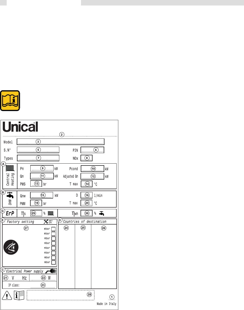
1.7 Data badge ...................................................................................................................................................................................................5
1.8 Water treatment ............................................................................................................................................................................................ 7
1.9 General warnings ..........................................................................................................................................................................................8
2 TECHNICAL FEATURES AND DIMENSIONS ...................................................................................................................................................9
2.1 Technical features ......................................................................................................................................................................................... 9
2.2 RHS view showing main components .........................................................................................................................................................10
2.3 Dimensions ................................................................................................................................................................................................. 11
2.4 Performance data .......................................................................................................................................................................................12
2.4.1 Performance DATA ErP ......................................................................................................................................................................13
3 INSTRUCTIONS FOR THE INSTALLER ...........................................................................................................................................................14
3.1 General warnings .......................................................................................................................................................................................14
3.2 Packaging ..................................................................................................................................................................................................15
3.3 Removal from the bed and insert foot ........................................................................................................................................................16
3.4 Boiler location in a boiler room ..................................................................................................................................................................16
3.6 Boiler connection ....................................................................................................................................................................................... 18
3.7 Gas connection..........................................................................................................................................................................................19
3.8 Connection return and flow system pipes..................................................................................................................................................20
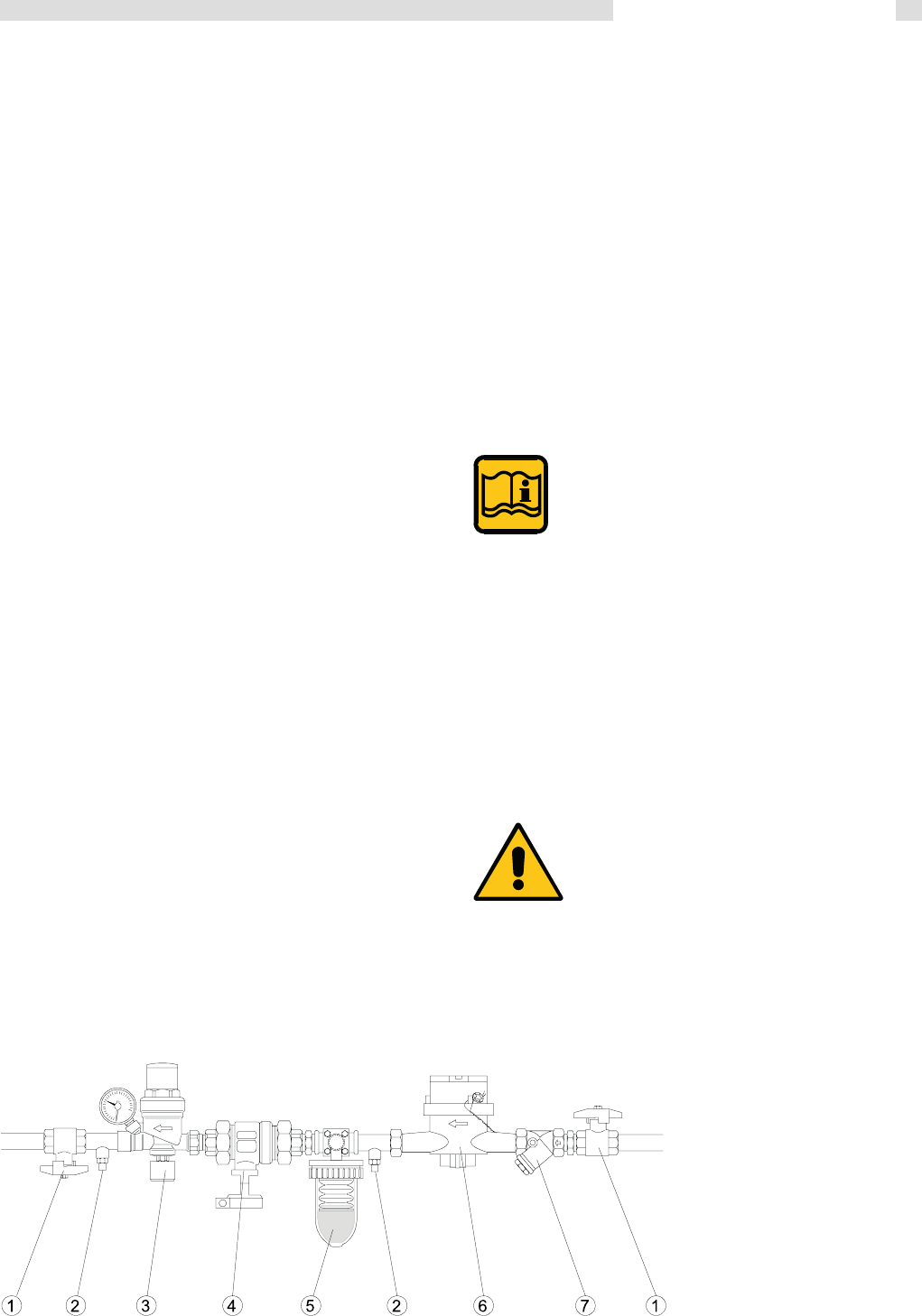
3.9 Additional safety and control devices, according to the Italian Law + primary circuit kit ...........................................................................21
3.10 Mixing header ............................................................................................................................................................................................ 22
3.11 Mixing header filter ....................................................................................................................................................................................22
3.12 Determination of primary boiler pump or boiler system pump ...................................................................................................................23
3.13 Ballstop valves ...........................................................................................................................................................................................23
3.14 Plate heat exchanger .................................................................................................................................................................................24
3.15 Primary circuit ............................................................................................................................................................................................24
3.16 Condensing drain ......................................................................................................................................................................................26
3.17 Flue chimney connection ...........................................................................................................................................................................27
3.18 Flue mainfold connection .......................................................................................................................................................................... 27
3.19 Electrical connection .................................................................................................................................................................................29
3.20 Wiring diagram ..........................................................................................................................................................................................30
CONNECTING RING PRIMARY (SUPPLIED WITH MODULAR PUMP)................................................................................................. 31
THERMOSTAT ON / OFF CONNECTIONS .............................................................................................................................................31
THERMOSTAT FBR 2 CONNECTION (room sensor) ..............................................................................................................................32
MODULATING THERMOSTAT CONNECTIONS ......................................................................................................................................33
3.21 FUNCTIONAL WIRING DIAGRAM ...........................................................................................................................................................34
3.22 WIRING DIAGRAM FOR CONNECTIONS AND MANAGING ................................................................................................................35
3.23 Installation examples (functional wiring and connections description) ......................................................................................................38
3.24 Cascade manager BCM ............................................................................................................................................................................43
3.25 Filling the system ....................................................................................................................................................................................... 44
3.26 Boiler Freeze protection .............................................................................................................................................................................44
3.27 Burner Adjustment .....................................................................................................................................................................................45
3.28 Emergency functions .............................................................................................................................................................................. 48
3.29 Lighting and shutting down procedures ..................................................................................................................................................... 49
4 SERVICING SCHEDULE ..................................................................................................................................................................................50
3
General Information
1.1 - SYMBOLS USED IN THIS GUIDE
When reading this guide particular care has to be given to the parts marked with the followings symbols:
1.2 - CORRECT USE OF THE APPLIANCE
The ALKON appliance has been designed utilizing today’s heating technology and in compliance with the
current safety regulations.However, following an improper use, dangers could arise for the safety and life
of the user or of other people, or damage could be caused to the appliance or other objects.The appliance
is designed to be used in pumped hot water central heating systems. Any other use of this appliance will be
considered improper. UNICAL declines any responsibility for any damages or injuries caused by an improper
use; in this case the risk is completely at the users responsibility. In order to use the appliance according
to the scopes it was designed for it is essential to carefully follow the instructions indicated in this guide.
1.3 - INFORMATION TO BE HANDED OVER TO THE USER
1
GENERAL INFORMATION
NOTE!
Suggestions for the
user
WARNING!
Indicates a potentially dangerous
situation for the product and the en-
vironment
DANGER!
Indicates serious danger
for your personal safety
and for your life
The user has to be instructed on the use and operation of his heating system, in particular:
Hand over these instructions to the end user, together with any other literature regarding this appliance,
placed inside the envelope contained in the packaging. The user has to keep these documents in a safe
place in order to always have them at hand for future reference.
Informtheuserontheimportanceofairventsandoftheueoutletsystem,stressingthefactthatisabsolutely
forbidden to make any alterations to the boiler.
Inform the user how to check the system’s water pressure as well as informing him how to restore the correct
pressure.
Explain the function of time and temperature controls, thermostats, heating controls and radiators, to ensure
the greatest possible fuel economy.
Remind the user that it is obligatory to carry out a comprehensive service annually and a combustion analysis
every two years (in compliance with the national law).
If the appliance is sold or transferred to another owner or if the present user moves home and leaves the
appliance installed, ensure yourself that the manual always follows the appliance so that it can be consulted
by the new owner and/or installer.
Failure to follow the instructions indicated in this guide, which is supplied with the boiler, could cause injury
to persons, animals or damage to property. The manufacturer shall not be held liable for any such injury
and/or damage.
4
General Information
WARNING!
The device should not be used by people with reduced physical, mental and sensory, experience and
knowledge. These people must be well-informed and supervised during the work. Children must be
supervised so they do not play with the appliance.
WARNING!
The installation, adjustment, and servicing of this appliance must be carried out by a competent person
and installed in accordance with the current standards and regulations. Failure to correctly install this
appliance could cause injury to persons, animals or damage to property. The manufacturer shall not be
held liable for any injury and/or damage.
DANGER!
Servicing or repairs of the appliance must be carried out by UNICAL authorised service technicians; UNICAL re-
commends drawing up a service contract. Bad or irregular servicing could compromise the safe operation of the
appliance, and could cause injury to persons, animals or damage to property for which UNICAL shall not be held
liable.
Modications to parts connected to the appliance
Donotcarryoutanymodicationstothefollowingparts:
- the boiler
- to the gas, air, water supply pipes and electrical current
- totheuepipe,safetyreliefvalveanditsdrainagepipe
- totheconstructivecomponentswhichinuencetheappliance’ssafeoperation
WARNING!
When tightening or loosening the screw pipe connections, use only adequate fork spanners.
The improper use and/or the use of inadequate equipment can cause damages (for example water or gas leakages).
WARNING!
Indications for appliances operating with propane gas
Ensure yourself that before installing the appliance the gas tank has been purged.
For a correct purging of the tank contact the liquid gas supplier or a competent person who has been legally authorized.
If the tank has not been correctly purged problems could occur during ignition.
If this occurs contact the liquid gas tank’s supplier.
Smell of gas
If you smell gas follow these safety indications:
- Do not turn on or off electrical switches
- Do no smoke
- Do not use the telephone
- Close the main gas tap
- Open all windows and doors where the gas leakage has occurred
- Inform the gas society or a company specialized in installing and servicing heating systems
Explosive and easily inammable substances
Donotuseorleaveexplosiveoreasilyinammablematerial(asforexample:petrol,paint,paper)intheroomwhere
the appliance has been installed.
1.4 - SAFETY WARNINGS
WARNINGS
The boiler has to be installed in such way to avoid,
under the foreseen operation conditions, the congelation of the water and
to prevent that the control devices are exposed to a temperature
lower than -15°C and higher than 40°C.
The boiler has to be protected against environmental variations with:
- The insulation of the hydraulic pipelines and the condensate evacuation
- TheadoptionofspecicantifreezeproductsintheC.H.installation.
5
General Information
When the appliance is installed on existing systems, ensure
yourself that:
- Theueoutletpipeissuitableforcondensingboilers,for
the temperature of the products of combustion, calculated
and manufactured according to the regulations in force. It
must be installed as much as possible in a straight line,
tested for soundness, insulated and must not have any
occlusions or restrictions.
- Theueoutletpipehasaconnectionforthedischargeof
condensate.
- The boiler room has a suitable outlet for the discharge of
condensate produce by the boiler.
- Theelectricalsystemhasbeenttedincompliancetothe
specicnormsandtheworkhasbeencarriedoutbya
competent person.
- Thecirculationpump’soutput,theheadandowdirection
are suitable.
- The gas feeding supply pipe and the eventual tank are
constructed according to the regulations in force.
- The expansion vessels assure the total absorption of the
dilatationoftheuidcontainedinthesystem.
- The system has been cleaned of impurities and lime scale.
When a Modulex boiler is installed onto an existing
heating system:
In case the replacement of an existing boiler in an old system can
be programmed, it
is necessary to thoroughly
clean out the system with a basic solution.
The system must be cleaned 4 weeks before
the substitution, with the system ring at a
temperature of 35°C to 40°C.
WARNING!
If it is noticed that a new Modulex has replaced,
in an old system the existing boiler without having first perfor-
med what said in the previous paragraph, Do not wash now
the system, as residual products, present in the circuit, could
lead to system gathering in the boiler body, causing damage.
UNICAL recommends contacting a specialised company for
water treatment.
Instead, if installing a Modulex boiler in a new system, it is
still recommended to thoroughly clean out the system with an
adequate product and fit a Y filter with two isolating valves onthe
boiler’s return pipe, so that, when necessary, it can be cleaned.
This filter will protect the boiler from the dirt coming from the
heating system.
When sizing pumps, it is necessary to take into consideration
the pressure losses which occurin the primary circuit.
1.6 - INSTALLATION ON EXISTING HEATING SYSTEMS
1.5 - STANDARD CODES FOR
INSTALLATION
The appliance must be installed in compliance to the instructions
contained in this manual.
Theinstallationmustbe carriedoutby acompetentqualied
engineer, whom will assume the responsibility of complying to
allthelocaland/ornationalregulationspublishedintheofcial
publications, as well as all the applicable codes of practice.
Before installing the appliance please contact the gas supply
company.
The installation must be carried in accordance to the codes of
practice, the regulations and the requirements hereby indicated
which constitute an indicative list, but not a complete one, as
these continue to undergo evolve devolpments.
Moreover, the boiler must be installed in accordance to all the
regulations regarding the boiler room, the building regulations
and the prescriptions regarding central heating plants in force
in the country where the boiler is installed.
The appliance must be installed, commissioned and serviced
according to the regulations in force. This is also valid for the
hydraulicsystem,theueoutletsystemandtheboilerlocation
room.
Failure to comply with these rules will
nullify the warranty
6
General Information
1.6 - TECHNICAL DATA PLATE
CE marking
TheCEmarkingcertiesthattheboilersmeet:
- The essential requirements of the gas appliance directive
(directive 2009/142/EEC)
- The essential requirements of the electromagnetic compat-
ibility directive (2004/108/EEC)
- Theessentialrequirementsoftheefciencydirective(92/42/
EEC)
- Theessentialrequirementsoftheefciencydirective(direc-
tive 2006/95/EEC)
The Technical data plate is placed
under the casing over the forehead
stirrup.
KEY:
1 = CE monitoring body
2 = Type of boiler
3 = Boiler model
4 = Number of stars (directive 92/42 EEC)
5 = (S.N°) Serial Number
6 = P.I.N.ProductIdenticationNumber
7 = Typesofapproveduegasexhaustcongurations
8 = (NOx)NOxClass
A = Heatingcircuitcharacteristics
9 = (Pn) Effective nominal output
10 = (Pcond) Effective output in condensation
11= (Qn)Maximumheatoutput
12= (AdjustedQn)Adjustedforratedheatoutput
13= (PMS)Max.heatingoperatingpressure
14= (Tmax)Max.heatingtemperature
B = Domestichotwatercircuitcharacteristics
15= (Qnw)Ratedheatoutputindomestichotwaterfunction
(if different to Qn)
16= (D)SpecicD.H.W.owrateaccordingtoEN625-EN
13203-1
19= (PMW)Max.domestichotwateroperatingpressure
20= (Tmax)Max.domestichotwatertemperature
C = Electricalcharacteristics
21= Electricalpowersupply
22 = Consumption
23 = Protection rating
D = Countries of destination
24 = Direct and indirect countries of destination
25 = Gas category
26 = Supply pressure
E = Factory settings
27 = Adjusted for gas type X
28 = Space for national brands
G = ErP
29=Seasonalspaceheatingenergyefciency
30 =EnergyefciencyinDHWproductionmode
7
General Information
1.8 - WATER TREATMENT
The chemical-physical characteristics of the filling water and
reinstatement water in heating systems are of fundamental
importance for guaranteeing correct and safe boiler operation.
Before filling the CH circuit with water, it is necessary to analyse
the water and decide for a proper treatment.
The purpose of this treatment is finalized to eliminate or sub-
stantially reduce the following problems:
- lime scale deposit
- corrosions
- deposits
- biological growths (moulds, bacteria, algae, fungi, etc)
The chemical treatment of the network water enables the
prevention of these problems and guarantees safe boiler
operation and economical advantages, in terms of mainte-
nance and global thermal efficiency.
The chemical analysis of the water enables us to obtain a lot
of information on the system’s condition and state of “health”.
It is essential to avoid any problems with the boiler.
The pH is a measure of the acidity or alkalinity of a solution.
The pH scale has a range of 0-14, where 7 is neutral.
Values inferior to 7 indicate acidity, values above 7 indicate
alkalinity.
The ideal pH value for water in heating systems fitted with
aluminium boilers is between 6,5 and 8, with a hardness
of 15°F.
In heating systems where the water has a value outside this ran-
ge, this considerably accelerates the destruction of the protective
oxidized layer which naturally develops inside the aluminium
bodies: if the pH is below 6, acidity is present, if it is above 8,
the water is alkaline or it is caused by an alkaline treatment (for
example phosphate or glycol used as an antifreeze) or in several
cases it is due to the natural formation of alkaline in the system.
Vice versa, if the pH value is between 6,5 and 8, the aluminium
surfaces of the boiler body are passivated and protected from
further corrosive attacks.
To minimize corrosion it is essential to use a scale inhibitor,
however in order for this to function correctly, the metallic
surfaces have to be clean.
The best corrosion inhibitors on sale also contain a pro-
tective system for aluminium which acts by stabilizing the
water’s pH value, preventing unforeseen variations.
We recommend that the heating system’s water pH value is
systematically controlled (minimum twice a year). In order
to do this, it is not necessary to run a chemical analysis in a
laboratory, but it is sufficient to use a simple analytical ‘kit’
contained in portable cases, easily found on sale.
Therefore, prior to filling the heating system with water it will be
necessary to fit the devices indicated in the figure below.
THE CONNECTION MUST BE FITTED ON THE
PRIMARY CIRCUIT’S RETURN PIPE DOWN-
STREAM OF THE CIRCULATING PUMP
All the necessary precautions must be taken in order to avoid
the formation and localization of oxygen in the system’s water.
For this reason, the plastic pipes used in underfloor heating
systems must be impermeable to oxygen.
If any antifreeze solutions are used ensure yourself that they are
compatible with aluminium and with any other components and
materials fitted on the system.
WARNING!
ANY DAMAGE CAUSED BY THE BOILER,
DUE TO THE FORMATION OF LIME SCALE
OR DUE TO CORROSIVE WATER WILL INVA-
LIDATE THE APPLIANCE WARRANTY.
1. Ball valve
2. Inspection pocket
3. Filling-up group
4. Disconnector
5. Scale reducing device
6. Litrecounter
(recommended)
7. “Y” filter
EXAMPLE OF SCALE REDUCING DEVICE CONNECTION FOR WATER TREATMENT
8
General Information
1.9 - GENERAL WARNINGS
This instruction manual is an integral and indispensable part
of the product and must be retained by the person in charge of
the appliance.
Please read carefully the instructions contained in this manual as
they provide important indications regarding the safe installation,
use and servicing of this appliance.
Keep this manual in a safe place for future reference.
The installation and servicing must be carried out in ac-
cordance with the regulations in force according to the
manufacturers instructions and by legally competent
authorized persons.
By a competent person, we imply a person who has a spe-
cic technical qualication in the eld of components for
central heating systems for domestic use, domestic hot
water production and servicing. The person must have the
qualications foreseen by the current laws in force.
Bad or irregular servicing could compromise the safe operation
of the appliance, and could cause injury to persons, animals or
damage to property. The manufacturer shall not be held liable
for any such injury and/or damage.
Before carrying out any cleaning or servicing turn off the electrical
supply to the boiler by means of the ON/OFF switch and/or by
means of the appropriate shutdown devices.
Do not obstruct the intake/outlet terminal ducts.
In the event of failure and/or faulty functioning of the appliance,
switch off the boiler. Do not attempt to make any repairs: contact
qualiedtechnicians.
Any repairs must be carried out by Unical authorized technicians
and using only original spare parts. Non-observance of the above
requirement may jeopardize the safety of the appliance.
Toguaranteetheefciencyandcorrectfunctioningoftheap-
pliance it is indispensable to have the boiler serviced annually
byaqualiedperson.
If the boiler remains unused for long periods, ensure that any
dangerous parts are rendered innocuous.
If the appliance is sold or transferred to another owner or if the
present user moves home and leaves the appliance installed,
ensure yourself that the manual always follows the appliance
so that it can be consulted by the new owner and/or installer.
Only original accessories must be used for all appliances sup-
plied with optionals or kits (including electrical ones).
This appliance must be used only for the purposes for which it
has been expressively designed. Any other use shall be consi-
dered incorrect and therefore dangerous (*).
9
Technical features and dimensions
TECHNICAL FEATURES
AND DIMENSIONS
2.1 - TECHNICAL FEATURES
• MODULEX is a compact, gas fired, Low NO
x
, condensing
boiler.
• made up by one sectional boiler body, suitable for a single
boiler working or directly as cascade
• Placeevenoutside(IPX5D)
• Low water content
• Fast response to load variations
• Flue terminal positionable on 3 sides
• Manifold unified delivery and return (everseble in simple way
p.16)
• Made up of two or more heating elements (2 to 7), cast alu-
minum / silicon / magnesium
• Modulating premix burners total radiation
• Each heating element without hydraulic interceptions
• One gas supply pipe (reversible)
• Modular power from 12 to 50 kW / element
TEMPERATURE CONTROL DEVICES:
• LOCALNTCsensor(eachheatingelement)
• Limitthermostatroom(eachheatingelement)
• flow NTC sensor (General)
• NTC sensor return (General)
• Safety thermostat approved (Order and install on ISPESL
device see page 18)
• FlowsensorBCM
Other safety devices (RACCOLTA R) see 3.6 pag. 18
Control panel (POP-UP) includes:
• ON-OFFswitchseepag.47
• Temperature control / boiler operator E8
• BCM(BoIIerCascadeManager)
• Fuses
• Limitthermostat>(over)350kW
• Airpressurefans
• Condensatelevelsensor
• Gaspressostat
• Smokepressostat(anti-obstruction)
• The whole group has heat sensors NTC control global tem-
perature on the flow and return..
Integral insulation with synthetic wool hypoallergenic
• Total premix burner, modulating burner with a “metal sponge”,
ad irraggiamento. Premixing into the fan. Automatic diafra-
ghm backflow of separation from the combustion chamber.
• Noise at maximum power of less than 49 dBA.
• Heatingoperation:determinationofinstantaneouspower
microprocessor control, with preset parameters for compa-
rison between temperature (or calculated from the external
temperatureregulation)andglobaltemperatureow.
• Operationmodes:
Ability to control power of the individual heating elements for
any calibration and / or assistance with access code confi-
dential.
Production of A.C.S. by NTC of priorities for control by
boiler feed pump or by three-way diverter valve controller
E8 included.
• Abilitytocontrolpoweroftheindividualheatingelements
• Controlofheatdemand:setpointtemperatureandlevelof
modulation.
2
• Monitoringofoperatingstatusandtemperature.
• Reportingofalarms.
• Settingparameters.
• Relaycontrolfortheactivationofaxedspeedpump
• Analogoutput0to10Vtocontrolamodulatingpump.
• Operationofemergencypreventsthedetentionfacilityasa
result of the interruption of communication with the control
system or any remote control unit:
• Withthepossibilityoftemperatureselectionthroughemer-
gencyresistorssuppliedwith“constantSetpoint:70°C,max
50%.
• Alarmmanagement
• Alarmresetinput.
• Relaywarningalarm.
• condensatecollectortankwithsiphonstainlesssteel
• Panelscompletewitheasilyremovablestainlesssteelpanels
paintedwithreadaptedforoutdoorinstallation
• condensatecollectiontankwithdraintrapandsmokechamber
in stainless steel.
• Built-inairvent
The application of heat can be generated by the Regolation / E8
operator or alternatively from BCM (boyler Cascade Manager)
The management logic provides the maximum number of
simultaneous operation of heating elements as possible in
order to maximize your productivity. As we provide high ex-
change surface as a function of output power. The items are
made to work so as to share equitably the operating time.
The hot water produced by the pump is pushed on the return
oftheringtotheprimaryowofthehydraulicseparator.From
here a second pump (system - see the diagrams suggested) will
arrange for the distribution to various users. The return chilled
water plant is sucked by the pump on the return through the
hydraulic separator to resume the cycle via the generator.
10
Technical features and dimensions
2.2 - R.H. SIDE VIEW, WITH MAIN COMPONENTS
Should a positioning of the ue connection be necessary on the left hand side of the boiler (the standard
is on the right) so please move the cover ‘A“ with each wiring connection, condensate level sensor, red
pressostat pipe on the rear side of the boiler. The rear side cover (just re-moved) has to be re-placed on the
right side of the boiler.
- Smoke and condensate evacuation connection on the R.H. side (forniture condition), L.H. side, BACK SIDE
order special BACK Flue kit
MODULEX EXT 100 - 116 - 150 - 200 : 00362154
MODULEX EXT 250 - 300 - 350 : 00362076
- C.H. flow connection on the R.H. side (forniture condition), L.H. side
- C.H. return connection on the R.H. side (forniture condition), L.H. side
- Gas connection on the R.H. side (forniture condition), L.H. side
55
Servicing schedule
Second phase - Cleaning
Remove the gaskets and the burners.
• Performcleaningoftheburnersonlybyblowing,withcom-
pressed air, acting from the “side flame”
• VerifyvisuallythestateofthespotweldingsoftheLproles
and the burner mesh.
The burner gaskets must be replaced at
every cleaning operation.
Wash with water the combustion chamber, avoiding to wet
the electrical harness
During this operation it will be necessary to ascertain that
the condensate drain pipe is free, so that the washing water
does not come out from the inspection hole.
Blow the combustion chamber with compressed air, trying to
remove all the dirt still fixed to the fins.
Once the washing of the aluminium sections is finished, make
sure the siphon for the evacuation of the condensate is free:
if necessary clean it
Ispect the smoke evacuation pipe and the chimney
Third phase – Reassembly
When reassembly, proceed in the reverse
order, taking care to tight the fixing screws
of the mixer/fan group to the body, with a
tightening torque of 13 Nm
WARNING
AT EACH MAINTENANCE OPERATION IT IS
COMPULSORY TO REPLACE THE SEALING
GASKETS ON EACH BURNER.
Spare parts code:
00251482 - KIT OF BURNER GASKETS
MODULEX (5 pz.)
95262823 - KIT BURNER MODULEX E8
• Beforelightingtheboilermakesurethesiphonhasbeenlled
with water.
• Beforeopening the gas feedingcock,previously unloosed,
make sure it is well tight. To do this open the gas cock and
check with a soap solution.
• Whenasingleburnerisstarted,checkimmediatelyforthe
soundness between its gas valve and the relevant premixing
chamber.
• Performthecombustionanalysischeckitsparameters.
• Makesurethatallthepressuretestnipples,previously
opened, have been closed.
• Afterthecleaningoftheboilerbodyand/ortheburners,re
position the burners in their seats.
• Positionthenewgasketsingraphite
COMPRESSED AIR
55

Hulp nodig? Stel uw vraag in het forum

Spelregels

Misbruik melden

Gebruikershandleiding.com neemt misbruik van zijn services uitermate serieus. U kunt hieronder aangeven waarom deze vraag ongepast is. Wij controleren de vraag en zonodig wordt deze verwijderd.

Product:

Bijvoorbeeld antisemitische inhoud, racistische inhoud, of materiaal dat gewelddadige fysieke handelingen tot gevolg kan hebben.

Bijvoorbeeld een creditcardnummer, een persoonlijk identificatienummer, of een geheim adres. E-mailadressen en volledige namen worden niet als privégegevens beschouwd.

Spelregels forum

Om tot zinvolle vragen te komen hanteren wij de volgende spelregels:

Belangrijk! Als er een antwoord wordt gegeven op uw vraag, dan is het voor de gever van het antwoord nuttig om te weten als u er wel (of niet) mee geholpen bent! Wij vragen u dus ook te reageren op een antwoord.

Belangrijk! Antwoorden worden ook per e-mail naar abonnees gestuurd. Laat uw emailadres achter op deze site, zodat u op de hoogte blijft. U krijgt dan ook andere vragen en antwoorden te zien.

Abonneren

Abonneer u voor het ontvangen van emails voor uw Unical MODULEX EXT 250 bij:


U ontvangt een email met instructies om u voor één of beide opties in te schrijven.


Ontvang uw handleiding per email

Vul uw emailadres in en ontvang de handleiding van Unical MODULEX EXT 250 in de taal/talen: Engels als bijlage per email.

De handleiding is 8,87 mb groot.


U ontvangt de handleiding per email binnen enkele minuten. Als u geen email heeft ontvangen, dan heeft u waarschijnlijk een verkeerd emailadres ingevuld of is uw mailbox te vol. Daarnaast kan het zijn dat uw internetprovider een maximum heeft aan de grootte per email. Omdat hier een handleiding wordt meegestuurd, kan het voorkomen dat de email groter is dan toegestaan bij uw provider.

Stel vragen via chat aan uw handleiding

Stel uw vraag over deze PDF

Andere handleiding(en) van Unical MODULEX EXT 250

Unical MODULEX EXT 250 Installatiehandleiding - Nederlands - 57 pagina's


Uw handleiding is per email verstuurd. Controleer uw email

Als u niet binnen een kwartier uw email met handleiding ontvangen heeft, kan het zijn dat u een verkeerd emailadres heeft ingevuld of dat uw emailprovider een maximum grootte per email heeft ingesteld die kleiner is dan de grootte van de handleiding.

Er is een email naar u verstuurd om uw inschrijving definitief te maken.

Controleer uw email en volg de aanwijzingen op om uw inschrijving definitief te maken

U heeft geen emailadres opgegeven

Als u de handleiding per email wilt ontvangen, vul dan een geldig emailadres in.

Uw vraag is op deze pagina toegevoegd

Wilt u een email ontvangen bij een antwoord en/of nieuwe vragen? Vul dan hier uw emailadres in.


Info