


-
beste,
Reageer op deze vraag Misbruik melden
graag handleiding in Nederlandse taal
mvg
huys Gesteld op 25-1-2023 om 16:09 -
ik krijg geen nederlandse handleiding van silver crest SL 65 Gesteld op 30-6-2011 om 08:43
Reageer op deze vraag Misbruik melden-
waar kan ik de nederlandse handleiding vinden DVB-S SL 65 Geantwoord op 2-1-2013 om 11:24
Waardeer dit antwoord (19) Misbruik melden
-
-
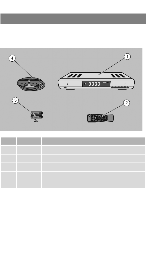
ik heb een afstandbediening die het niet meer doet ik zou graag een nieuwe hebben het nummer is DVB-S SL 65/12. de onkosten wil ik graag betalen
Reageer op deze vraag Misbruik melden
het aders is A.Ketelaars
Endeldijk 18
3079 VC Rotterdam
Nederland Gesteld op 20-4-2011 om 16:56-
beste,
Waardeer dit antwoord Misbruik melden
ik zag exemplaren op ebay en op amazon.
mvg,
kathy Geantwoord op 29-6-2011 om 21:03
-
-
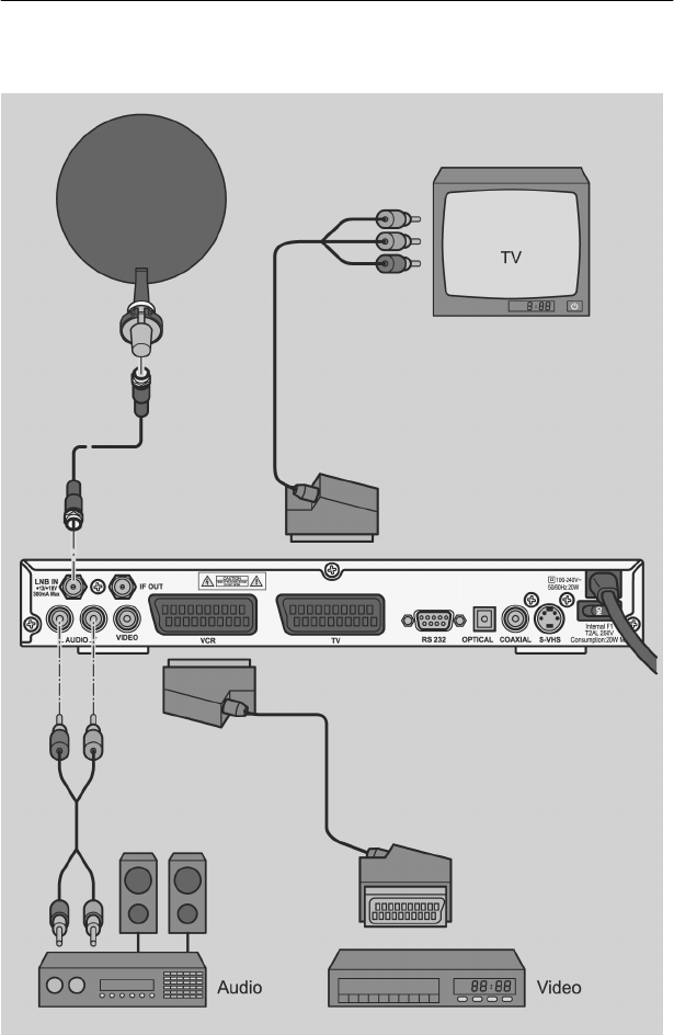
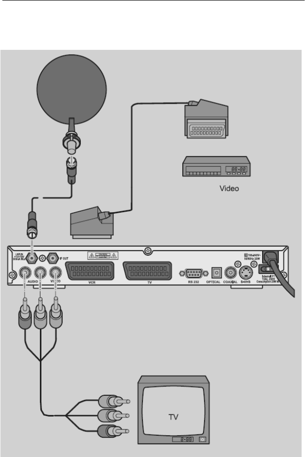
Ik heb een probleem bij het installeren van de Silvercrest SL65. Het plaatsen en richten van de schotel is goed verlopen. 75 tot 80% ontvangst, alle menu's werken prima maar toch slaag ik er niet in een programma op het scherm te krijgen. Wie kent de oplossing of wat doe ik verkeerd? Gesteld op 5-4-2010 om 12:59
Reageer op deze vraag Misbruik melden-
als ge geen programma's op uw tv krijgt hoe kan u dan weten dat u 70% ontvangst heeft? Geantwoord op 22-8-2012 om 18:06
Waardeer dit antwoord (13) Misbruik melden
-
-
Reeds verscheidene malen geprobeerd. Ontvangst zoals u maar er komt niets door. Wat was de oplossing //// Geantwoord op 13-7-2013 om 12:46
Waardeer dit antwoord (6) Misbruik melden -
hoeveel graden moet de schotel staan om de juiste beeld te hebben aub? Gesteld op 19-10-2009 om 15:20
Reageer op deze vraag Misbruik melden-
fakjoe !!!!!!!!!!!!!!!!!! Geantwoord op 1-8-2014 om 18:33
Waardeer dit antwoord Misbruik melden
-
