605351
7
Verklein
Vergroot
Pagina terug
1/18
Pagina verder
USER'S MANUAL
CAUTION
Read all precautions and instruc-
tions in this manual before using
this equipment. Save this manual
for future reference.
Serial Number Decal
Model No. NETL11520
Serial No.
Find the serial number in the location
shown below. Write the serial number
in the space above for reference.
www.iconeurope.com
Visit our website at
Part No. 183913 R0602A Printed in USA © 2002 ICON Health & Fitness, Inc.
ORDERING REPLACEMENT PARTS
To order replacement parts, contact the ICON Health & Fitness, Ltd. office, or write:
ICON Health & Fitness, Ltd.
Unit 4
Revie Road Industrial Estate
Revie Road, Beeston
Leeds, LS11 8JG
UK
Tel:
Fax: 0 (044) 113 387 7125
When ordering parts, please be prepared to give the following information:
the MODEL NUMBER of the product (NETL11520)
the NAME of the product (NordicTrack
®
2500 R treadmill)
the SERIAL NUMBER of the product (see the front cover of this manual)
the KEY NUMBER and DESCRIPTION of the part(s) (see the PART LIST on pages 30 and 31 and the EX-
PLODED DRAWING attached in the centre of this manual)
08457 089 009
QUESTIONS?
As a manufacturer, we are com-
mitted to providing complete
customer satisfaction. If you
have questions, or if there are
missing parts, please call:
Or write:
ICON Health & Fitness, Ltd.
Unit 4
Revie Road Industrial Estate
Revie Road
Beeston
Leeds
LS11 8JG
email: csuk@iconeurope.com
08457 089 009
Class H Fitness Product
TABLE OF CONTENTS
IMPORTANT PRECAUTIONS . . . . . . . . . . . . . . . . . . . . . . . . . . . . . . . . . . . . . . . . . . . . . . . . . . . . . . . . . . . . . . . . .3
BEFORE YOU BEGIN . . . . . . . . . . . . . . . . . . . . . . . . . . . . . . . . . . . . . . . . . . . . . . . . . . . . . . . . . . . . . . . . . . . . . . .5
ASSEMBLY . . . . . . . . . . . . . . . . . . . . . . . . . . . . . . . . . . . . . . . . . . . . . . . . . . . . . . . . . . . . . . . . . . . . . . . . . . . . . . .6
HOW TO USE THE CHEST PULSE SENSOR . . . . . . . . . . . . . . . . . . . . . . . . . . . . . . . . . . . . . . . . . . . . . . . . . . . .8
OPERATION AND ADJUSTMENT . . . . . . . . . . . . . . . . . . . . . . . . . . . . . . . . . . . . . . . . . . . . . . . . . . . . . . . . . . . . .9
HOW TO FOLD AND MOVE THE TREADMILL . . . . . . . . . . . . . . . . . . . . . . . . . . . . . . . . . . . . . . . . . . . . . . . . . .23
TROUBLESHOOTING . . . . . . . . . . . . . . . . . . . . . . . . . . . . . . . . . . . . . . . . . . . . . . . . . . . . . . . . . . . . . . . . . . . . . .25
CONDITIONING GUIDELINES . . . . . . . . . . . . . . . . . . . . . . . . . . . . . . . . . . . . . . . . . . . . . . . . . . . . . . . . . . . . . . .28
PART LIST . . . . . . . . . . . . . . . . . . . . . . . . . . . . . . . . . . . . . . . . . . . . . . . . . . . . . . . . . . . . . . . . . . . . . . . . . . . . . . .30
ORDERING REPLACEMENT PARTS . . . . . . . . . . . . . . . . . . . . . . . . . . . . . . . . . . . . . . . . . . . . . . . . . .Back Cover
Note: An EXPLODED DRAWING is attached in the centre of this manual.
31
NordicTrack is a registered trademark of ICON Health & Fitness, Inc.
2
Key No. Qty. Description Key No. Qty. Description
104 1 Spring
105 1 Lock Pin Collar
106 1 Lock Knob Sleeve
107 1 Lock Knob Spacer
108 1 Lock Knob
109* 1 Latch Assembly
110 1 Upright
111 4 Handrail Bolt
112 4 Handrail Washer
113 4 Handrail Bushing
114 2 Handrail Spacer
115 1 Grounding Bracket
116 2 Upright Endcap
117 2 Endcap Star Washer
118 1 Lift Frame Bushing
119 2 Endcap Spring
120 3 Nylon Washer
121 2 Motor Pivot Bushing
122 1 Motor Pivot Sleeve
123 1 Splitter
124 1 Ferrite Box
125 1 Chest Pulse Sensor
126 1 Chest Strap
# 1 14” Blue Wire, 2F
# 1 4” Blue Wire, 2F
# 1 4” Black Wire, 2F
# 1 12” Green Wire, 2 Ring
# 3 8” Green Wire, F/Ring
# 1 7” Green Wire, M/Ring
# 1 4” Green Wire, F/Ring
# 1 User's Manual
# 1 14” White Wire, 2F
# 2 10” White WIre, 2F
* Includes all parts shown in box
# These parts are not illustrated
30 3
1. It is the responsibility of the owner to ensure
that all users of this treadmill are adequately
informed of all warnings and precautions.
2. Use the treadmill only as described in this
manual.
3. Place the treadmill on a level surface, with at
least 2,5 m (8 ft.) of clearance behind it and
0.5 m (2 ft.) on each side. Do not place the
treadmill on a surface that blocks any air
openings. To protect the floor or carpet from
damage, place a mat under the treadmill.
4. Keep the treadmill indoors, away from mois-
ture and dust. Do not put the treadmill in a
garage or covered patio, or near water.
5. Do not operate the treadmill where aerosol
products are used or where oxygen is being
administered.
6. Keep children under the age of 12 and pets
away from the treadmill at all times.
7. The treadmill should not be used by persons
weighing more than 115 kg (250 lbs.).
8. Never allow more than one person on the
treadmill at a time.
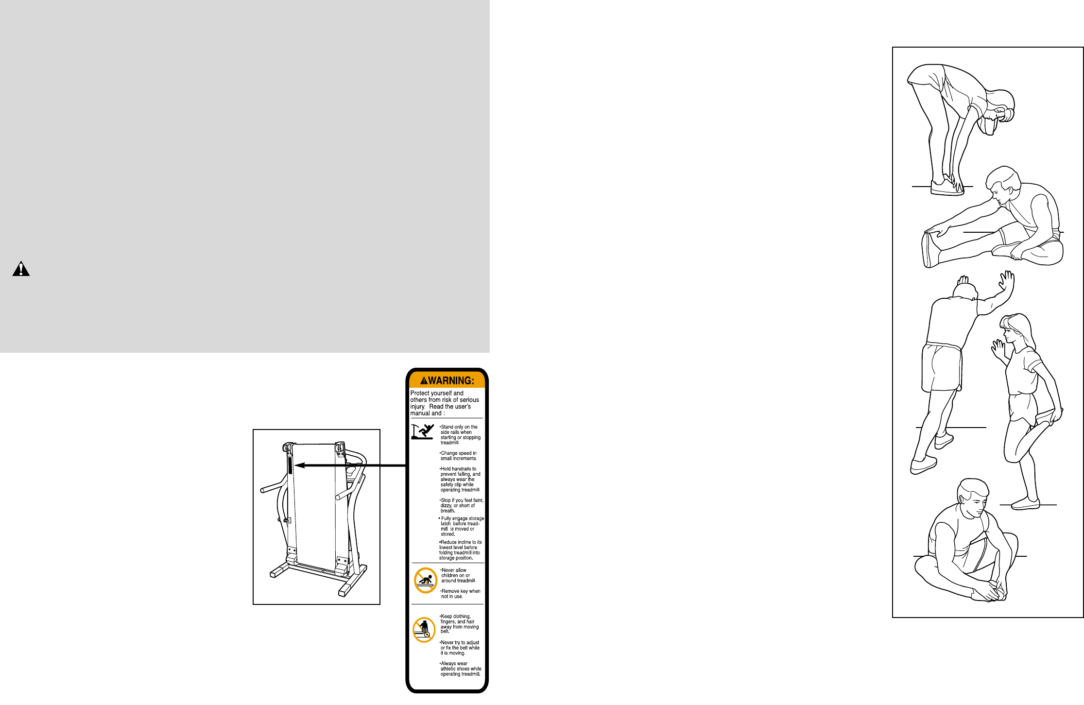
9. Wear appropriate exercise clothes when
using the treadmill. Do not wear loose clothes
that could become caught in the treadmill.
Athletic support clothes are recommended for
both men and women. Always wear athletic
shoes. Never use the treadmill with bare feet,
wearing only stockings, or in sandals.
10. When connecting the power cord (see page 9),
plug the power cord into an earthed circuit. No
other appliance should be on the same circuit.
When replacing the fuse, an ASTA approved
BS1362 type should be fitted to the fuse car-
rier. A 13 amp fuse should be used.
11. If an extension cord is needed, use only a 3-
conductor, 1 mm
2
(14-gauge) cord that is no
longer than 1.5 m (5 ft.).
12. Keep the power cord and the surge suppres-
sor away from heated surfaces.
13. Never move the walking belt whilst the power
is turned off. Do not operate the treadmill if
the power cord or plug is damaged, or if the
treadmill is not working properly. (See
BEFORE YOU BEGIN on page 5 if the tread-
mill is not working properly.)
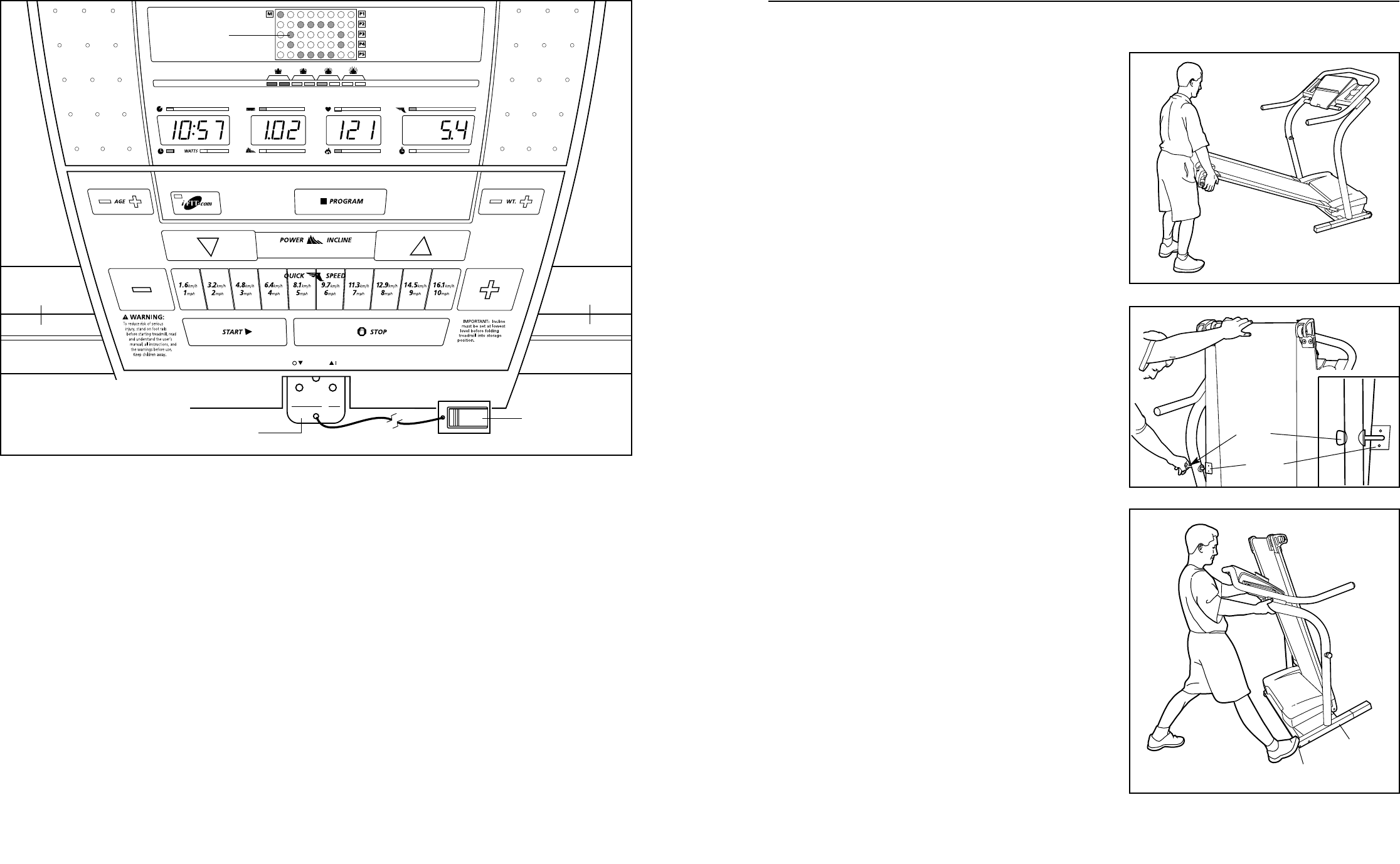
14. Never start the treadmill whilst you are stand-
ing on the walking belt. Always hold the
handrails whilst using the treadmill.
15. The treadmill is capable of high speeds.
Adjust the speed in small increments to avoid
sudden jumps in speed.
16. Using hand weights and not holding the
handrails may compromise your ability to
maintain your balance. Hand weights should
be used only by experienced users.
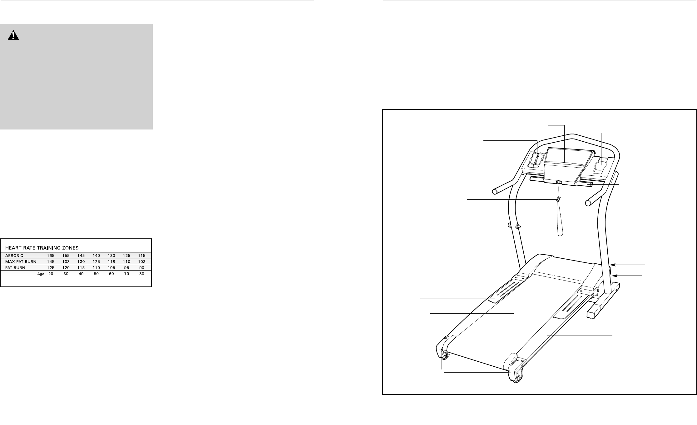
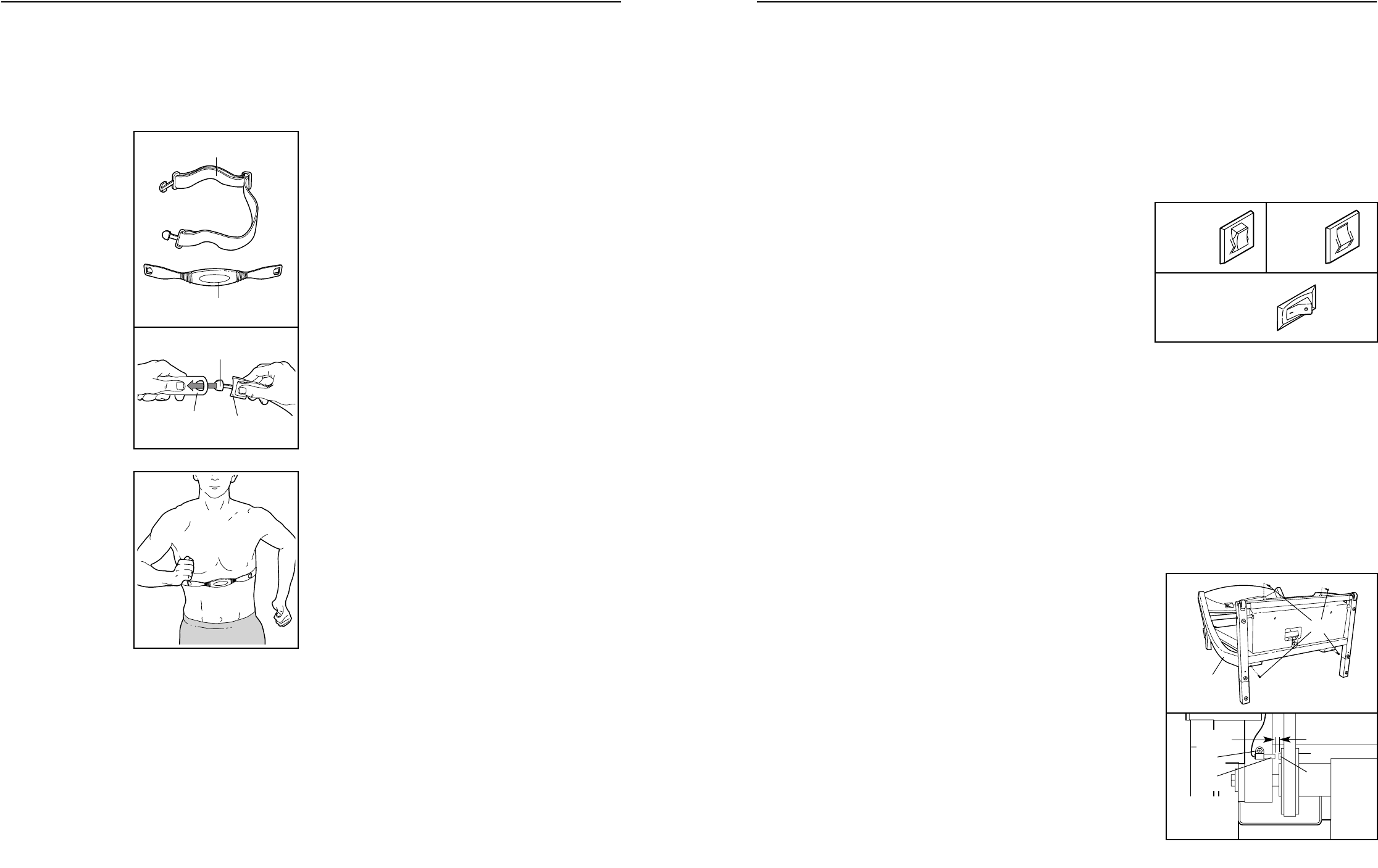
17. The pulse sensors are not medical devices.
Various factors, including the user's move-
ment, may affect the accuracy of heart rate
readings. The pulse sensors are intended only
as exercise aids in determining heart rate
trends in general.
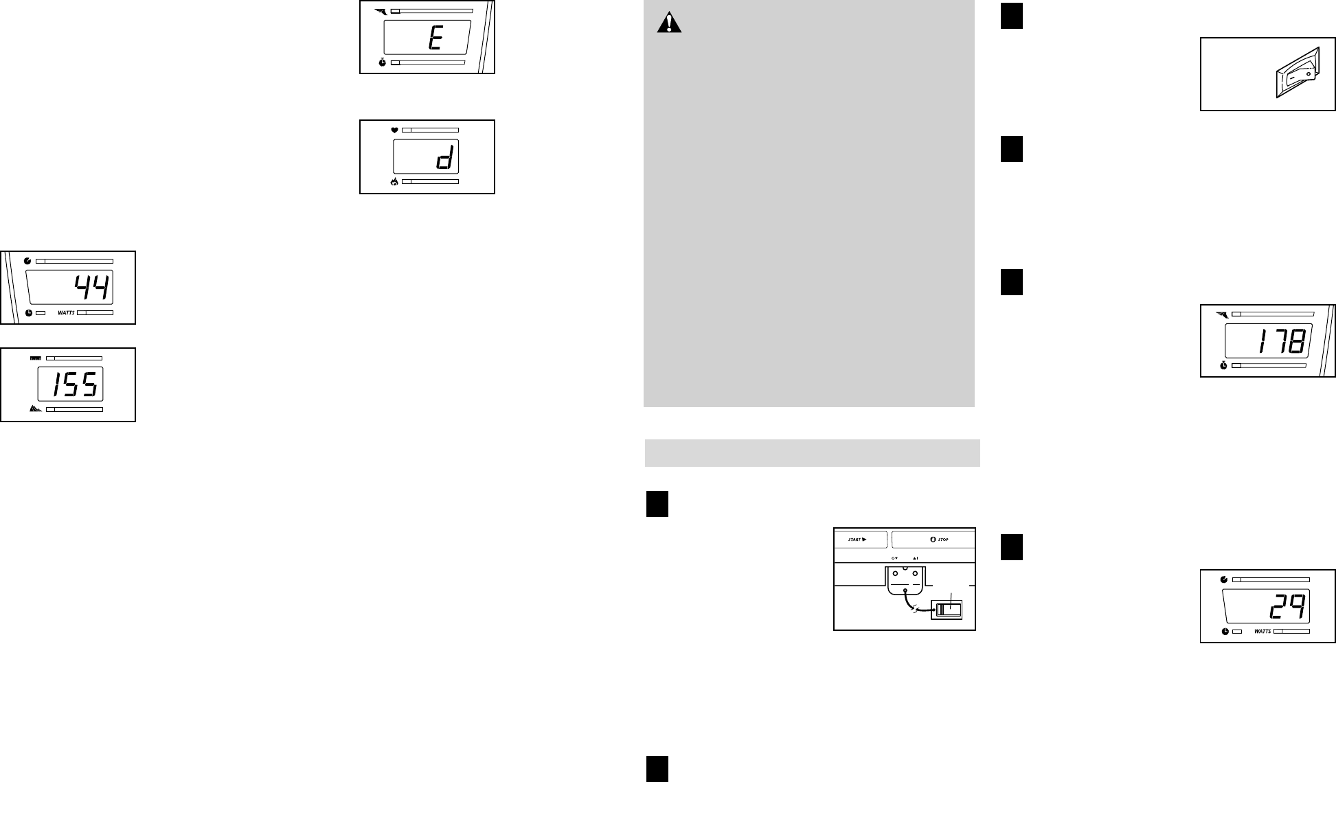
18. Never leave the treadmill unattended whilst it
is running. Always remove the key, unplug
the power cord, and move the on/off switch to
the off position when the treadmill is not in
use. (See the drawing on page 5 for the loca-
tion of the on/off switch.)
19. Do not change the incline of the treadmill by
placing objects under the treadmill.
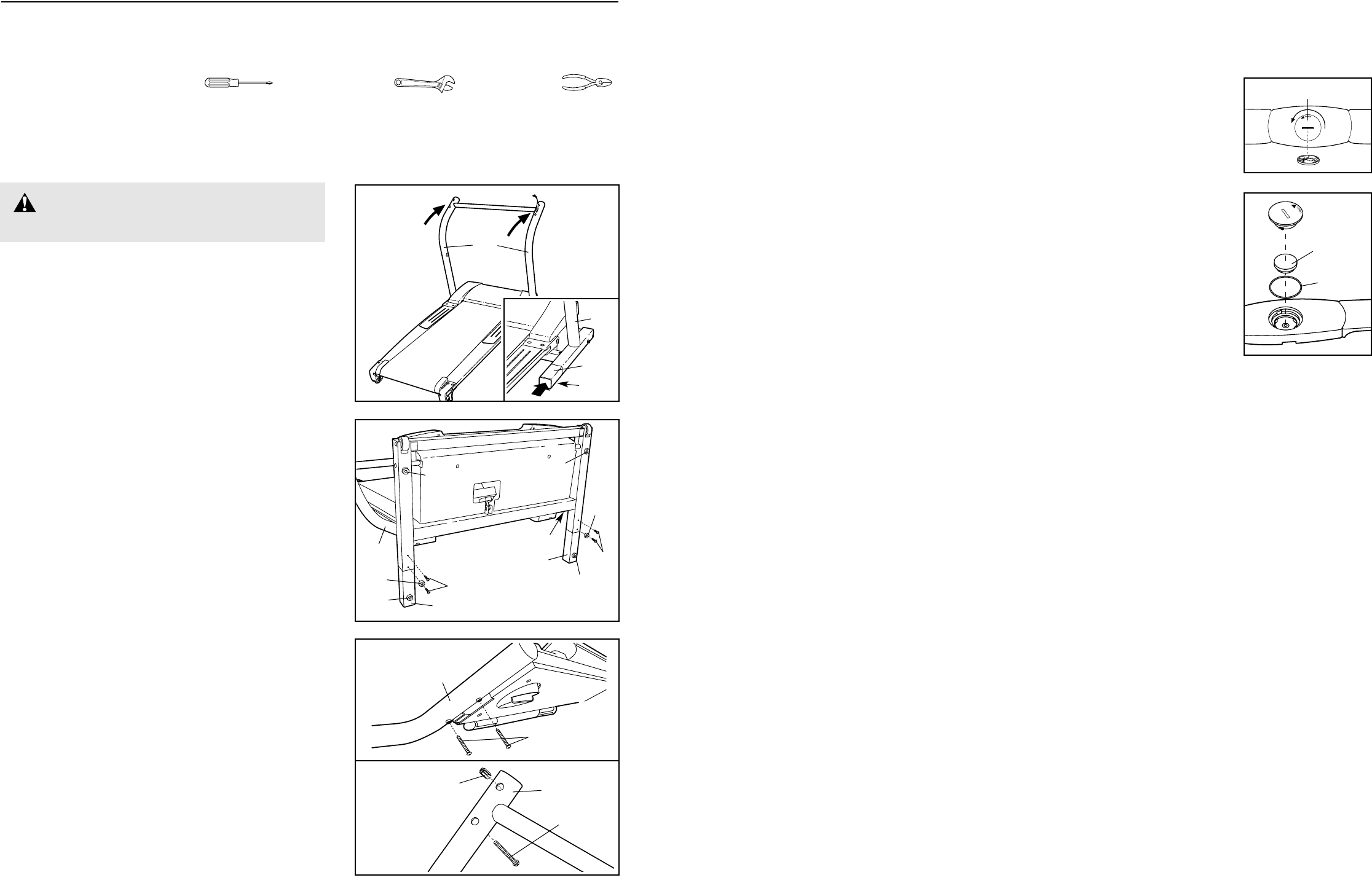
20. Do not attempt to raise, lower, or move the
treadmill until it is properly assembled. (See
ASSEMBLY on page 6, and HOW TO FOLD
AND MOVE THE TREADMILL on page 23.) You
must be able to safely lift 20 kg (45 lbs.) in
order to raise, lower, or move the treadmill.
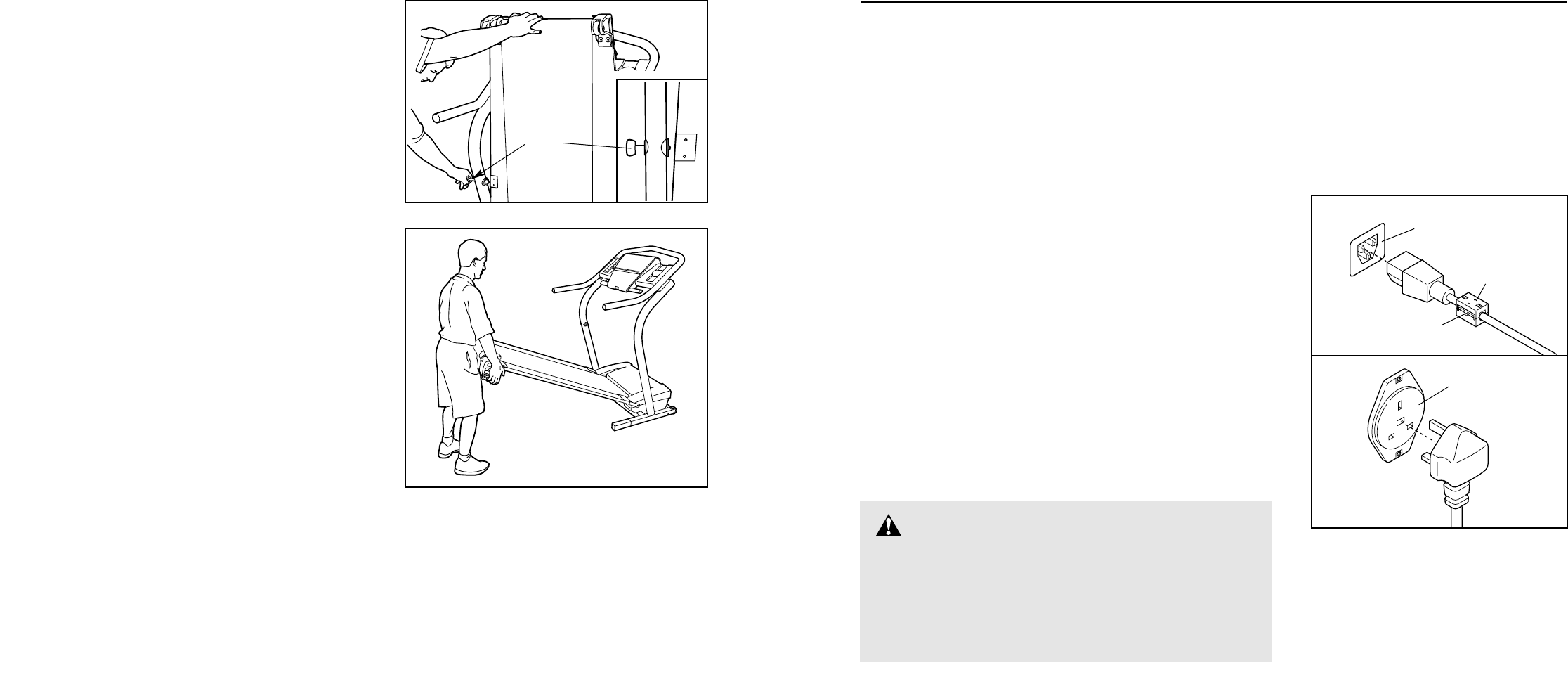
21. When folding or moving the treadmill, make
sure that the storage latch is fully closed.
WARNING:To reduce the risk of burns, fire, electric shock, or injury to persons, read the
following important precautions and information before operating the treadmill.
IMPORTANT PRECAUTIONSPART LIST—Model No. NETL11520 R0602A
To locate the parts listed below, see the EXPLODED DRAWING attached in the centre of this manual.
Key No. Qty. Description Key No. Qty. Description
1 1 Allen Wrench
2 2 Wheel Bolt
3 1 Left Rear Endcap
4 2 Roller Adj. Lock Washer
5 2 Rear Roller Adj. Bolt
6 2 Rear Wheel
7 8 Front Wheel Nut/Frame Pivot Nut
8 8 Endcap Screw
9 1 Roller Guard (Left)
10 1 Right Roller Guard
11 1 Right Rear Endcap
12 1 Roller Ground Wire
13 1 Filter Wire
14 1 Rear Roller
15 1 Warning Decal
16 1 Latch Plate
17 2 Latch Plate Screw
18 2 Frame Pivot Bolt
19 1 Left Front Endcap
20 2 Belt Guide
21 1 Foot Grip (Left)
22 1 Walking Belt
23 1 Walking Deck
24 1 Foot Grip (Right)
25 1 Power Board
26 1 Right Front Endcap
27 2 Support Bracket Screw
28 1 Support Bracket
29 1 Front Roller/Pulley
30 1 Magnet
31 6 Console Screw (Long)
32 2 Thrust Washer
33 2 Frame Pivot Bushing
34 2 Frame Pivot Spacer
35 1 Reed Switch
36 1 Reed Switch Clip
37 1 iFIT.com Wire
38* 1 Motor Assembly
39 1 Flywheel/Pulley
40 1 Motor Belt
41 1 Motor Pivot Nut
42 4 Motor Tension Nut/Lift Frame Nut
43 1 Motor Tension Washer
44 2 Hand Weights
45 1 Motor Pivot Bolt
46 1 Motor
47 1 Lift Frame
48 1 Motor Star Washer
49 10 Screw
50 1 Jack
51 1 Key/Clip
52 1 Incline Motor Bolt (Top)
53 8 Endcap Washer
54 1 Incline Motor Stop
55 8 Endcap Nut
56 2 Motor Tension Bolt/
Incline Motor Bolt, Lower
57 1 Incline Motor
58 1 Front Roller Bolt
59 4 Plastic Stand-off
60 1 Electronic Plate
61 1 Controller
62 1 Motor Controller Wire
63 1 Power Cord Set
64 1 Receptical
65 1 On/Off Switch
66 2 Long Belly Pan Screw
67 1 Audio Wire Nut
68 1 Circuit Breaker
69 2 Static Decal
70 1 12” Audio Wire
71 1 Belly Pan
72 4 3/4” Screw
73 1 Filter
74 1 Choke
75 3 Base Pad
76 1 Console Base
77 1 Book Holder
78 1 Console
79 2 Handrail Endcap
80 2 Pulse Grip
81 4 Pulse Grip Screw
82 10 Short Console Screw
83 1 Console Back
84* 2 Extension Leg Assy.
85 2 Extension Leg Endcap
86 8 Base Screw
87 2 Incline Motor Spacer
88 2 Extension Leg
89 1 Handrail
90 4 Thick Base Pad
91 1 Motor Hood
92 1 8” Wire Tie
93 2 Cable Tie Clamp
94 2 Clamp Screw
95 1 Releasable Tie
96 2 Lift Pivot Bolt
97 2 Front Wheel Bolt
98 2 Front Wheel
99 1 Incline Motor Guard
100 1 Upright Grommet
101 1 Upright Wire
102 1 Lock Pin
103 1 Pin Clip
22. When using iFIT.com CD’s and videos, an
electronic “chirping” sound will alert you
when the speed and/or incline of the treadmill
is about to change. Always listen for the
“chirp” and be prepared for speed and/or in-
cline changes. In some instances, the speed
and/or incline may change before the per-
sonal trainer describes the change.
23. When using iFIT.com CD’s and videos, you
can manually override the speed and incline
settings at any time by pressing the speed
and incline buttons. However, when the next
“chirp” is heard, the speed and/or incline will
change to the next settings of the CD or video
program.
24. Always remove iFIT.com CD’s and videos
from your CD player or VCR when you are not
using them.
25. Inspect and properly tighten all parts of the
treadmill regularly.
26. Never insert or drop any object into any
opening.
27.
DANGER:Always unplug the power
cord immediately after use, before cleaning
the treadmill, and before performing the main-
tenance and adjustment procedures de-
scribed in this manual. Never remove the
motor hood unless instructed to do so by an
authorised service representative. Servicing
other than the procedures in this manual
should be performed by an authorised service
representative only.
28. This treadmill is intended for in-home use
only. Do not use this treadmill in any commer-
cial, rental, or institutional setting.
WARNING:Before beginning this or any exercise program, consult your physician. This
is especially important for persons over the age of 35 or persons with pre-existing health problems.
Read all instructions before using. ICON assumes no responsibility for personal injury or property
damage sustained by or through the use of this product.
SAVE THESE INSTRUCTIONS
The decal shown has been placed on your treadmill. If the decal is missing, or if
it is not legible, please call our Customer Service Department to order a free re-
placement decal (see ORDERING REPLACEMENT PARTS on the back cover of
this manual). Apply the decal in the location shown.
Note: The decal shown at the
right is 49% of actual size.
4 29
SUGGESTED STRETCHES
The correct form for several basic stretches is shown at the right. Move slowly as you stretch—never bounce.
1. Toe Touch Stretch
Stand with your knees bent slightly and slowly bend forward
from your hips. Allow your back and shoulders to relax as you
reach down toward your toes as far as possible. Hold for 15
counts, then relax. Repeat 3 times. Stretches: Hamstrings, back
of knees and back.
2. Hamstring Stretch
Sit with one leg extended. Bring the sole of the opposite foot to-
ward you and rest it against the inner thigh of your extended leg.
Reach toward your toes as far as possible. Hold for 15 counts,
then relax. Repeat 3 times for each leg. Stretches: Hamstrings,
lower back and groin.
3. Calf/Achilles Stretch
With one leg in front of the other, reach forward and place your
hands against a wall. Keep your back leg straight and your back
foot flat on the floor. Bend your front leg, lean forward and move
your hips toward the wall. Hold for 15 counts, then relax. Repeat
3 times for each leg. To cause further stretching of the achilles
tendons, bend your back leg as well. Stretches: Calves, achilles
tendons and ankles.
4. Quadriceps Stretch
With one hand against a wall for balance, reach back and grasp
one foot with your other hand. Bring your heel as close to your
buttocks as possible. Hold for 15 counts, then relax. Repeat 3
times for each leg. Stretches: Quadriceps and hip muscles.
5. Inner Thigh Stretch
Sit with the soles of your feet together and your knees outward.
Pull your feet toward your groin area as far as possible. Hold for
15 counts, then relax. Repeat 3 times. Stretches: Quadriceps
and hip muscles.
1
2
3
4
5
Congratulations for selecting the new NordicTrack
®
2500 R treadmill. The 2500 R treadmill combines ad-
vanced technology with innovative design to help you
get the most from your workouts in the convenience of
your home. And when you’re not exercising, the
unique 2500 R can be folded up, requiring less than
half the floor space of other treadmills.
For your benefit, read this manual carefully before
using the treadmill. If you have questions after read-
ing the manual, please call our Customer Service
Department at 08457 089 009. To help us assist you,
please note the product model number and serial num-
ber before calling. The model number is NETL11520.
The serial number can be found on a decal attached to
the treadmill (see the front cover of this manual for the
location).
Before reading further, please familiarise yourself with
the parts that are labelled in the drawing below.
BEFORE YOU BEGIN
Handrail
Console
Hand Weights
Lock Knob
Book Holder
Key/Clip
Circuit Breaker
On/Off Switch
Walking Belt
Flexible Walking Platform
Foot Pad
Rear Roller
Adjustment Bolts
Water Bottle Holder*
Handgrip Pulse Sensor
RIGHT SIDE
LEFT SIDE
*No water bottle is included.
28 5
CONDITIONING GUIDELINES
The following guidelines will help you to plan your ex-
ercise program. For more detailed exercise informa-
tion, obtain a reputable book or consult your physician.
EXERCISE INTENSITY
Whether your goal is to burn fat or to strengthen your
cardiovascular system, the key to achieving the
desired results is to exercise with the proper intensity.
The proper intensity level can be found by using your
heart rate as a guide. The chart below shows recom-
mended heart rates for fat burning and aerobic exercise.
To find the proper heart rate for you, first find your age
near the bottom of the chart (ages are rounded off to
the nearest ten years). Next, find the three numbers
above your age. The three numbers define your “train-
ing zone.” The lower two numbers are recommended
heart rates for fat burning; the higher number is the
recommended heart rate for aerobic exercise.
To measure your heart rate during exercise, use the
handgrip pulse sensor or the chest pulse sensor.
Fat Burning
To burn fat effectively, you must exercise at a relatively
low intensity level for a sustained period of time.
During the first few minutes of exercise, your body
uses easily accessible carbohydrate calories for en-
ergy. Only after the first few minutes does your body
begin to use stored fat calories for energy. If your goal
is to burn fat, adjust the speed and incline of the tread-
mill until your heart rate is near the lowest number in
your training zone.
For maximum fat burning, adjust the speed and incline
of the treadmill until your heart rate is near the middle
number in your training zone.
Aerobic Exercise
If your goal is to strengthen your cardiovascular sys-
tem, your exercise must be “aerobic.” Aerobic exercise
is activity that requires large amounts of oxygen for
prolonged periods of time. This increases the demand
on the heart to pump blood to the muscles, and on the
lungs to oxygenate the blood. For aerobic exercise,
adjust the speed and incline of the treadmill until your
heart rate is near the highest number in your training
zone.
WORKOUT GUIDELINES
Each workout should include the following three parts:
A Warm-up—Start each workout with 5 to 10 minutes
of stretching and light exercise. A proper warm-up in-
creases your body temperature, heart rate and circula-
tion in preparation for exercise.
Training Zone Exercise—After warming up, increase
the intensity of your exercise until your pulse is in your
training zone for 20 to 60 minutes. (During the first few
weeks of your exercise program, do not keep your
pulse in your training zone for longer than 20 minutes.)
Breathe regularly and deeply as you exercise—never
hold your breath.
A Cool-down—Finish each workout with 5 to 10 min-
utes of stretching to cool down. This will increase the
flexibility of your muscles and will help prevent post-ex-
ercise problems.
EXERCISE FREQUENCY
To maintain or improve your condition, complete three
workouts each week, with at least one day of rest be-
tween workouts. After a few months, you may com-
plete up to five workouts each week if desired. The key
to success is to make exercise a regular and enjoyable
part of your everyday life.
WARNING:Before beginning this
or any exercise program, consult your physi-
cian. This is especially important for individu-
als over the age of 35 or individuals with pre-
existing health problems.
The pulse sensors are not medical devices.
Various factors, including the user's move-
ment, may affect the accuracy of heart rate
readings. The pulse sensors are intended only
as exercise aids in determining heart rate
trends in general.
3. See drawing 3a. Whilst another person holds the
Handrails (89), thread Handrail Bolts (111) two to three
turns into the two holes in each Handrail. Then, remove
the Handrail Bolts.
See drawing 3b. Pinch the tabs on the Grounding Bracket
(115) so that the tabs will fit into the indicated hole in the
left Upright (110). Then, insert the Grounding Bracket into
the hole as far as possible.
Note: It may be helpful to set the Handrails (89) on the
Uprights (110) and loosely thread a Handrail Bolt (111)
into the left Upright and the left Handrail. Tip the
Handrails, if necessary, to thread in the Handrail Bolt.
Have another person support the Handrails as you com-
plete the remaining steps.
ASSEMBLY
Assembly requires two people. Set the treadmill in a cleared area and remove all packing materials. Do not
dispose of the packing materials until assembly is completed. Assembly requires the included allen wrench
and your own phillips screwdriver , adjustable wrench , and wire cutters .
Note: The underside of the treadmill walking belt is coated with high-performance lubricant. During shipping, a
small amount of lubricant may be transferred to the top of the treadmill or the shipping carton. This is a normal
condition and does not affect treadmill performance. If there is lubricant on top of the walking belt or foot pads,
simply wipe off the lubricant with a soft cloth and a mild, non-abrasive cleaner.
2. With the help of a second person, carefully tip the
Uprights (110) down as shown. Make sure that the
Extension Legs (88) remain in the Uprights.
Attach each Extension Leg (88) with two Base Screws
(86) and a Base Pad (75) as shown.
With the help of a second person, carefully tip the
Uprights (110) back to the vertical position.
Note: One replacement Thick Base Pad (90) may be in-
cluded.
1. With the help of a second person, carefully raise the
Uprights (110) to the position shown.
See the inset drawing. Insert one of the Extension Legs
(88) into the treadmill as shown. Make sure that the
Thick Base Pad (90) is on the bottom. (Note: It may be
helpful to tip the Uprights (110) forward as you insert the
Extension Leg.) Insert the other Extension Leg (not
shown) in the same way.
1
110
86
88
110
110
86
88
90
90
75
90
90
75
2
90
88
110
6 27
110
111
111
89
115
3a
3b
PROBLEM: The chest pulse sensor does not function properly
SOLUTION: a. If the chest pulse sensor does not function properly, refer to CHEST PULSE SENSOR TROU-
BLE-SHOOTING on page 7.
b. If the chest pulse sensor still does not function properly, the battery
should be changed. To replace the battery, locate the battery cover
on the back of the sensor unit. Insert a coin into the slot in the cover,
and turn the cover counterclockwise to the “open” position. Remove
the cover.
Next, remove the old battery from the sensor unit. Insert a new CR
2032 battery, making sure that the writing is on top. Make sure that
the rubber gasket is in place in the sensor unit. Reattach the battery
cover and turn it to the closed position.
CR2032
Battery
Rubber
Gasket
Battery Cover
WARNING: Do not plug in the power
cord until the treadmill is completely assembled.
b
7. Make sure that all parts are tightened before you use the treadmill. Keep the included allen wrench in a
secure place. The allen wrench is used to adjust the walking belt (see page 26). To protect the floor or car-
pet from damage, place a mat under the treadmill.
5. Insert two Handrail Bolts (111) with Handrail Washers
(112) and Handrail Bushings (113) into the right Upright
(110) and the right Handrail Spacer (114). Turn the
Handrail Bushings so they fit against the Upright with the
thick sides of the Bushings toward the centre of the tread-
mill (refer to the inset drawing). Lift the right Handrail (89)
slightly and align the Bolts with the holes in the Handrail.
Loosely thread the Bolts into the Handrail. Do not
tighten the Bolts yet.
See the inset drawing. Remove the Handrail Bolt (111)
used in step 3. Reach inside the left Upright (110) and
spread the tabs on the Grounding Bracket (115) to allow a
Bolt to pass through the Grounding Bracket. Attach the left
Handrail (89) as described above. Make sure that the
Handrail Bushings (113) are turned properly and that the
Bolt goes through the Grounding Bracket. Tighten all
four Handrail Bolts. Press an Upright Endcap (116) into
each Upright.
5
111
111
112
113
Thick
Side
110
115
116
89
89
113
112
4. Pull the Upright Wire Harness (101) up through a
Handrail Spacer (114). Place the Handrail Spacer on the
right Upright (110) as shown, with the cutout turned to-
ward the treadmill (see inset drawing A). Place the other
Handrail Spacer on the left Upright, with the cutout turned
toward the treadmill.
Connect the Upright Wire Harness (101) to the wires ex-
tending from the Console Base (76). Insert the connec-
tors and the Upright Wire Harness into the hole in the
Console Base (refer to inset drawing B).
Set the Handrail (89) on the Handrail Spacers (114),
being careful not to pinch the Upright Wire Harness (101).
4
101
110
89
76
114
110
114
76
101
A
B
Cutout
26 7
114
6. Make sure the Lock Knob Sleeve (106) is pressed into
the left Upright (110).
Make sure that the Lock Pin Collar (105) and the Spring
(104) are on the Lock Pin (102). Insert the Lock Pin into
the Lock Knob Sleeve (106) and the left Upright (110).
Next, press the Lock Knob Spacer (107) onto the left
Upright. Tighten the Lock Knob (108) onto the Lock Pin.
110
107
106
108
104
105
102
6
PROBLEM: The walking belt slows when walked on
SOLUTION: a. If an extension cord is needed, use only a 3-conductor, 1mm
2
(14-gauge) cord that is no longer
than 1.5 m (5 ft.).
b. If the walking belt is overtightened, treadmill perfor-
mance may decrease and the walking belt may be-
come damaged. Remove the key and UNPLUG THE
POWER CORD. Using the allen wrench, turn both
rear roller adjustment bolts counterclockwise, 1/4 of a
turn. When the walking belt is properly tightened, you
should be able to lift each side of the walking belt 5 to
7 cm (3 to 4 in) off the walking platform. Be careful to
keep the walking belt centred. Plug in the power cord,
insert the key and run the treadmill for a few minutes.
Repeat until the walking belt is properly tightened.
c. If the walking belt still slows when walked on, please call our Customer Service Department, toll-
free.
PROBLEM: The walking belt is off-centre or slips when walked on
SOLUTION: a. If the walking belt is off-centre, first remove the key and
UNPLUG THE POWER CORD. If the walking belt has
shifted to the left, use the allen wrench to turn the left
rear roller bolt clockwise 1/2 of a turn. If the walking belt
has shifted to the right, turn the left rear roller bolt coun-
terclockwise 1/2 of a turn. Be careful not to overtighten the
walking belt. Plug in the power cord, insert the key, and
run the treadmill for a few minutes. Repeat until the walk-
ing belt is centred.
b. If the walking belt slips when walked on, first remove the
key and UNPLUG THE POWER CORD. Using the allen
wrench, turn both rear roller bolts clockwise, 1/4 of a turn.
When the walking belt is correctly tightened, you should
be able to lift each side of the walking belt 5 to 7 cm (3 to
4 in) off the walking platform. Be careful to keep the walk-
ing belt centred. Plug in the power cord, insert the key and
carefully walk on the treadmill for a few minutes. Repeat
until the walking belt is properly tightened.
PROBLEM: The incline of the treadmill does not change correctly or does not change when iFIT.com
CD’s and videos are played
SOLUTION: a. With the key in the console, press one of the Incline buttons. Whilst the incline is changing, re-
move the key. After a few seconds, re-insert the key. The treadmill will automatically rise to the
maximum incline level and then return to the minimum level. This will recalibrate the incline system.
Rear Roller Adjustment Bolts
5–7 cm
b
a
b
8 25
TROUBLESHOOTING
Most treadmill problems can be solved by following the steps below. Find the symptom that applies, and
follow the steps listed. If further assistance is needed, please call our Customer Service Department.
PROBLEM: The power does not turn on
SOLUTION: a. Make sure that the power cord is plugged into a properly earthed outlet (see page 9). If an extension
cord is needed, use only a 3-conductor, 1 mm
2
(14-gauge) cord that is no longer than 1.5 m (5 ft.).
b. After the power cord has been plugged in, make sure that the key is fully inserted into the console.
c. Check the circuit breaker located on the treadmill
near the power cord. If the switch protrudes as
shown, the circuit breaker has tripped. To reset the
circuit breaker, wait for five minutes and then press
the switch back in.
d. Check the on/off switch located on the treadmill
near the power cord. The switch must be in the on
position.
PROBLEM: The power turns off during use
SOLUTION: a. Check the circuit breaker located on the treadmill frame near the power cord (see c. above). If the
circuit breaker has tripped, wait for five minutes and then press the switch back in.
b. Make sure that the power cord is plugged in. Unplug the power cord, wait for five minutes, and
then plug the power cord back in.
c. Remove the key from the console. Reinsert the key fully into the console.
d. Make sure that the on/off switch is in the on position.
e. If the treadmill still will not run, please call our Customer Service Department.
PROBLEM: The displays of the console do not function properly
SOLUTION: a. Remove the key from the console and unplug the
power cord. Carefully tip the treadmill down as
shown in drawing a. Remove the Screws (66) from the
hood. Raise the Uprights (110) and carefully remove
the hood.
Locate the Reed Switch (35) and the Magnet (30) on
the left side of the Pulley (29). Turn the Pulley until the
Magnet is aligned with the Reed Switch. Make sure
that the gap between the Magnet and the Reed
Switch is about 3 mm (1/8 in.). If necessary, loosen
the Screw (49) and move the Reed Switch slightly.
Retighten the Screw. Re-attach the hood, and run the
treadmill for a few minutes to check for a correct
speed reading.
Tripped
c
Reset
30
66
110
a
29
Top
View
49
3mm
35
On
Position
d
HOW TO PUT ON THE CHEST PULSE SENSOR
Before you use the chest pulse sensor, please read all
instructions on this page.
The chest pulse
sensor consists of
two components:
the chest strap and
the sensor unit.
If the chest strap is
not connected to
the sensor unit,
refer to drawing 2.
Insert one of the
tabs on the chest
strap through one
end of the sensor
unit. Make sure to
press the end of the
sensor unit under
the buckle on the
chest strap—the
tab should be al-
most flush with the
sensor unit.
Next, wrap the chest
pulse sensor around
your chest and at-
tach the other end of
the chest strap to
the sensor unit.
Adjust the length of
the chest strap, if
necessary. The
chest pulse sensor
should be under
your clothes, tight
against your skin,
and as high under the pectoral muscles or breasts as
is comfortable. Make sure that the logo on the sensor
unit is facing forward and is right-side-up.
Pull the sensor unit away from your body a few inches
and locate the two electrode areas on the inner side.
The electrode areas are the areas covered by shallow
ridges. Using saline solution such as saliva or contact
lens solution, wet both electrode areas. Return the
sensor unit to a position against your chest.
CHEST PULSE SENSOR CARE AND MAINTENANCE
Thoroughly dry the chest pulse sensor after each
use. The chest pulse sensor is activated when the
electrode areas are wetted and the heart rate
monitor is put on; the chest pulse sensor shuts off
when it is removed and the electrode areas are
dried. If the chest pulse sensor is not dried after
each use, it may remain activated longer than nec-
essary, draining the battery prematurely.
Store the chest pulse sensor in a warm, dry place.
Do not store the chest pulse sensor in a plastic bag
or other container that may trap moisture.
Do not expose the chest pulse sensor to direct
sunlight for extended periods of time.
Do not expose the chest pulse sensor to tempera-
tures above 50° C (122° F) or below -10° C (14° F).
Do not excessively bend or stretch the sensor unit
when using or storing the chest pulse sensor.
Clean the sensor unit periodically using a damp
cloth; never use alcohol, abrasives, or chemicals.
The chest strap may be hand washed and air dried.
CHEST PULSE SENSOR TROUBLESHOOTING
The instructions on the following pages explain how
the chest pulse sensor is used with the console. If
the letters “PLS” appear in the Heart Rate/Calories
display, or if the displayed heart rate is excessively
high or low, try the steps below.
Make sure that you are wearing the chest pulse sen-
sor as described at the left. If the chest pulse sensor
does not function when positioned as described,
move it slightly lower or higher on your chest.
Use saline solution such as saliva or contact lens
solution to wet the two electrode areas on the sensor
unit. If heart rate readings do not appear until you
begin perspiring, re-wet the electrode areas.
As you walk or run on the treadmill, position your-
self near the centre of the walking belt. For the con-
sole to display heart rate readings, the user must
be within arm’s length of the console.
Chest Strap
Sensor Unit
Tab
Buckle
Sensor
Unit
1
2
HOW TO USE THE CHEST PULSE SENSOR
24 9
OPERATION AND ADJUSTMENT
THE PERFORMANT LUBE
TM
WALKING BELT
Your treadmill features a walking belt coated with PERFORMANT LUBE
TM
, a high-performance lubricant. IMPOR-
TANT: Never apply silicone spray or other substances to the walking belt or the walking platform. Such
substances will deteriorate the walking belt and cause excessive wear.
HOW TO PLUG IN THE POWER CORD
This product must be earthed. If it should malfunction or break
down, earthing provides a path of least resistance for electric
current to reduce the risk of electric shock. This product is equipped
with a cord having an equipment-earthing conductor and an earth-
ing plug.
Two power cords are included. Select the one that will fit your
outlet. See drawing 1. Plug the indicated end of the power cord
into the socket on the treadmill. Next, lift the tab on the ferrite
box and clamp the ferrite box around the power cord. See
drawing 2. Plug the power cord into an appropriate outlet that
is properly installed and earthed in accordance with all local
codes and ordinances. Important: The treadmill is not compati-
ble with GFCI-equipped outlets.
If the power cord is damaged, it must be replaced with a manufac-
turer-recommended power cord.
DANGER:Improper connection of the equip-
ment-earthing conductor can result in an increased risk
of electric shock. Check with a qualified electrician or
serviceman if you are in doubt as to whether the prod-
uct is properly earthed. Do not modify the plug provided
with the product—if it will not fit the outlet, have a
proper outlet installed by a qualified electrician.
1
2
Socket on treadmill
Outlet
Tab
Ferrite Box
HOW TO LOWER THE TREADMILL FOR USE
1. Hold the upper end of the treadmill with your right hand as
shown. Using your left hand, pull the lock knob to the left
and hold it. Pivot the treadmill down until the frame is past
the pin on the lock knob.
2. Hold the treadmill firmly with both hands, and lower the
treadmill to the floor. CAUTION: To decrease the possi-
bility of injury, bend your legs and keep your back
straight.
Knob
10 23
HOW TO FOLD AND MOVE THE TREADMILL
HOW TO FOLD THE TREADMILL FOR STORAGE
Before folding the treadmill, adjust the incline to the
lowest position. If this is not done, the treadmill may be per-
manently damaged. Remove the key and unplug the power
cord. CAUTION: You must be able to safely lift 20 kg (45
lbs.) in order to raise, lower, or move the treadmill.
1. Hold the treadmill with your hands in the locations shown
at the right. CAUTION: To decrease the possibility of in-
jury, bend your legs and keep your back straight. As
you raise the treadmill, make sure to lift with your legs
rather than your back. Raise the treadmill about halfway
to the vertical position.
2. Move your right hand to the position shown and hold the
treadmill firmly. Using your left hand, pull the lock knob to
the left and hold it. Raise the treadmill until the catch plate
is past the pin on the lock knob. Slowly release the lock
knob. Make sure that the pin is securely holding the
catch plate.
To protect the floor or carpet from damage, place a
mat under the treadmill. Keep the treadmill out of
direct sunlight. Do not leave the treadmill in the stor-
age position in temperatures above 30° C (85° F).
HOW TO MOVE THE TREADMILL
Before moving the treadmill, convert the treadmill to the stor-
age position as described above. Make sure that the pin
on the lock knob is securely holding the catch plate.
1. Hold the handrails as shown and place one foot against a
wheel.
2. Tilt the treadmill back until it rolls freely on the front wheels.
Carefully move the treadmill to the desired location. Never
move the treadmill without tipping it back. To reduce
the risk of injury, use extreme caution whilst moving
the treadmill. Do not attempt to move the treadmill
over an uneven surface.
3. Place one foot on wheel, and carefully lower the treadmill
until it is resting in the storage position.
Base
Front Wheels
Knob
Catch
FEATURES OF THE CONSOLE
The advanced console offers an impressive array of
features to help you get the most from your exercise.
When the manual mode of the console is selected, the
speed and incline of the treadmill can be changed with
a touch of a button. As you exercise, the console will
provide continuous exercise feedback. You can even
measure your heart rate using the handgrip pulse sen-
sor or the chest pulse sensor.
Three preset workout programs are also offered. Each
program automatically controls the speed and incline
of the treadmill to give you an effective workout. The
included hand weights let you add upper-body exer-
cise to your workouts as well. You can even create
your own custom workout programs and store them in
memory for future use.
The console also features iFIT.com interactive technol-
ogy. IFIT.com technology is like having a personal trainer
right in your home. Using the included audio cable, you
can connect the treadmill to your home stereo, portable
stereo, or computer and play special iFIT.com CD pro-
grams (iFIT.com CD’s are available separately).
IFIT.com CD programs automatically control the speed
and incline of the treadmill as a personal trainer guides
you through every step of your workout. High-energy
music provides added motivation. Each CD features two
programs designed by certified personal trainers.
In addition, you can connect the treadmill to your VCR
and TV and play iFIT.com video programs (videocas-
settes are available separately). Video programs offer
the same benefits as iFIT.com CD programs, but add
the excitement of working out with a class and an
instructor—the hottest new trend at health clubs.
With the treadmill connected to your computer, you
can also go to our Web site at www.iFIT.com and ac-
cess basic programs, audio programs, and video pro-
grams directly from the internet. See www.iFIT.com for
details.
For information about iFIT.com CD’s or videocas-
settes, send an e-mail to workouts@iFIT.com.
To use the manual mode of the console, follow the
steps beginning on page 12. To use a preset program,
see page 13. To create and use a custom program,
see pages 15 and 16. To use an iFIT.com CD or
video program, see page 19. To use an iFIT.com
program directly from our Web site, see page 21.
Program
Display
Pulse
Sensor
Pulse
Sensor
Clip
Key
Note: If there is a thin sheet
of clear plastic on the face
of the console, remove it.
22 11
THE INFORMATION MODE/DEMO MODE
The console features an information mode that keeps
track of the total number of hours that the treadmill has
been operated and the total number of miles that the
walking belt has moved. The information mode also
allows you to switch the console from miles per hour to
kilometres per hour. In addition, the information mode
allows you to turn on and turn off the demo mode.
To select the information mode, hold down the Stop
button whilst inserting the key into the console. When
the information mode is selected, the following informa-
tion will be shown:
The Time/Watts display will
show the total number of
hours that the treadmill has
been used.
The Distance/Incline
display will show the total
number of miles that the
walking belt has moved.
An E, for English miles, or an
M, for metric kilometres, will
appear in the Speed/ Pace
display. Press the Speed +
button to change the unit of
measurement.
IMPORTANT: The Heart
Rate/Calories display
should be blank. If a “d” ap-
pears in the display, the con-
sole is in the “demo” mode.
This mode is intended to be
used only when a treadmill is displayed in a store.
When the console is in the demo mode, the power cord
can be plugged in, the key can be removed from the
console, and the displays and indicators on the console
will automatically light in a preset sequence, although
the buttons on the console will not operate. If a “d” ap-
pears in the Heart Rate/Calories display when the
information mode is selected, press the Speed –
button so the Heart display is blank.
To exit the information mode, remove the key from the
console.
GETTING STARTED
Attach the clip to the waistband of your clothes.
Stand on the foot pads
of the treadmill. Find
the clip attached to the
key and slide the clip
onto the waistband of
your clothes. Next, in-
sert the key into the
console. Test the clip
by carefully taking a few steps backward until
the key is pulled from the console. If the key is
not pulled from the console, adjust the posi-
tion of the clip as needed. Then, remove the key
from the console.
Plug in the power cord.
See HOW TO PLUG IN THE POWER CORD on
page 9.
Move the on/off switch to the on position.
Locate the on/off switch
on the treadmill near the
power cord. Move the
on/off switch to the on
position.
Insert the key fully into the console.
Stand on the foot pads of the treadmill. Make sure
that the clip is securely attached to the waistband
of your clothes. Next, insert the key into the con-
sole. After a moment, various displays and indica-
tors on the console will light.
Enter your weight.
Although you can use
the console without
entering your weight, the
console will display your
calorie expenditure more
accurately if you enter
your weight. To enter your weight, press either of
the Weight (WT.) buttons. The current weight set-
ting will appear in the Speed/Pace display. Press
the Weight buttons again to enter your weight. A
few seconds after the buttons are pressed, the
weight setting will disappear from the display.
Your weight will then be saved in memory.
Enter your age, if necessary.
Although you can use
the console without en-
tering your age, some
features on our Web site
may require you to enter
your age (see page 21).
To enter your age, press either of the AGE but-
tons. The current age setting will appear in the
Time/Watts display. Press the AGE buttons again
to enter your age. A few seconds after the buttons
are pressed, the age setting will disappear from the
display. Your age will then be saved in memory.
6
5
4
3
2
1
CAUTION:Before operating the
console, read the following precautions.
Do not stand on the walking belt when turn-
ing on the power.
Always wear the clip (see the drawing below)
whilst operating the treadmill.
Adjust the speed in small increments to
avoid sudden jumps in speed.
The pulse sensor is not a medical device.
Various factors, including the user’s move-
ment, may affect the accuracy of heart rate
readings. The pulse sensor is intended only
as an exercise aid in determining heart rate
trends in general.
To reduce the possibility of electric shock,
keep the console dry. Avoid spilling liquids
on the console and place only a sealed water
bottle in the water bottle holder.
On
Position
Clip
7

Hulp nodig? Stel uw vraag in het forum

Spelregels

Misbruik melden

Gebruikershandleiding.com neemt misbruik van zijn services uitermate serieus. U kunt hieronder aangeven waarom deze vraag ongepast is. Wij controleren de vraag en zonodig wordt deze verwijderd.

Product:

Bijvoorbeeld antisemitische inhoud, racistische inhoud, of materiaal dat gewelddadige fysieke handelingen tot gevolg kan hebben.

Bijvoorbeeld een creditcardnummer, een persoonlijk identificatienummer, of een geheim adres. E-mailadressen en volledige namen worden niet als privégegevens beschouwd.

Spelregels forum

Om tot zinvolle vragen te komen hanteren wij de volgende spelregels:

Belangrijk! Als er een antwoord wordt gegeven op uw vraag, dan is het voor de gever van het antwoord nuttig om te weten als u er wel (of niet) mee geholpen bent! Wij vragen u dus ook te reageren op een antwoord.

Belangrijk! Antwoorden worden ook per e-mail naar abonnees gestuurd. Laat uw emailadres achter op deze site, zodat u op de hoogte blijft. U krijgt dan ook andere vragen en antwoorden te zien.

Abonneren

Abonneer u voor het ontvangen van emails voor uw NordicTrack 2500R - NETL11520 bij:


U ontvangt een email met instructies om u voor één of beide opties in te schrijven.


Ontvang uw handleiding per email

Vul uw emailadres in en ontvang de handleiding van NordicTrack 2500R - NETL11520 in de taal/talen: Engels als bijlage per email.

De handleiding is 0,96 mb groot.


U ontvangt de handleiding per email binnen enkele minuten. Als u geen email heeft ontvangen, dan heeft u waarschijnlijk een verkeerd emailadres ingevuld of is uw mailbox te vol. Daarnaast kan het zijn dat uw internetprovider een maximum heeft aan de grootte per email. Omdat hier een handleiding wordt meegestuurd, kan het voorkomen dat de email groter is dan toegestaan bij uw provider.

Stel vragen via chat aan uw handleiding

Stel uw vraag over deze PDF

Andere handleiding(en) van NordicTrack 2500R - NETL11520

NordicTrack 2500R - NETL11520 Gebruiksaanwijzing - Nederlands - 18 pagina's

NordicTrack 2500R - NETL11520 Gebruiksaanwijzing - Deutsch - 18 pagina's

NordicTrack 2500R - NETL11520 Gebruiksaanwijzing - Français - 18 pagina's


Uw handleiding is per email verstuurd. Controleer uw email

Als u niet binnen een kwartier uw email met handleiding ontvangen heeft, kan het zijn dat u een verkeerd emailadres heeft ingevuld of dat uw emailprovider een maximum grootte per email heeft ingesteld die kleiner is dan de grootte van de handleiding.

Er is een email naar u verstuurd om uw inschrijving definitief te maken.

Controleer uw email en volg de aanwijzingen op om uw inschrijving definitief te maken

U heeft geen emailadres opgegeven

Als u de handleiding per email wilt ontvangen, vul dan een geldig emailadres in.

Uw vraag is op deze pagina toegevoegd

Wilt u een email ontvangen bij een antwoord en/of nieuwe vragen? Vul dan hier uw emailadres in.


Info