www.hugo-mueller.de BA HUpr -22989 - 2014 -07 -V03 - ED - A3 Seite 1
Amaster clock Sit 1 / 2
(SC 58.17 pr
Please note the:
Thly
found !
Only the c
valid.
!!ATTENTION !! DANGRIELECTRI!!!
=> Instaonly by a skilled pe
=> Discon!!!
=> Defecttel!!!
Connect the suppl
Warranty void i
The el
external influences exce
Installation and assembl
codes
The dispos
SC 58. DIN aster clock )
Techn slav-cloc -line (SL)
SC 58.07 pr
Connection di
Numbe 1
Outpu: 24V
Outpu: 3
Conn. t: 17
Max. nclocks:apsla clocks
Outpu: P
Pulse N =
Duri10/mi
Pulength: 2sec.
(Pullengt adju)
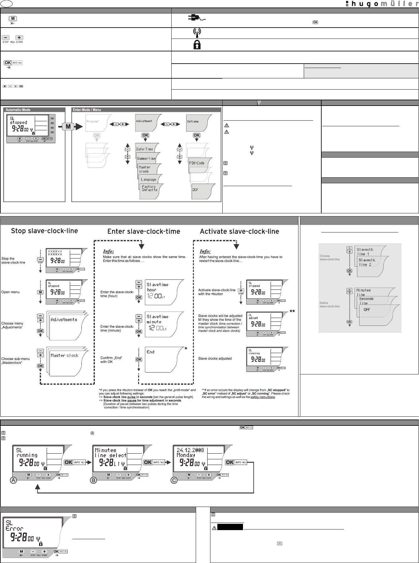
The t
The dis [flashing ].
Press -butt The a-mode.
(Dispthe time aslave- clo- line ().
The master clock idate and
dayli The sl-cloc -line is pres-line
activ / sta 12:Slave- cloc- line (SL) is stopp .
Power supply master cl S c
Connee supp
Connection slave- clo-line (SL) => m a clock (See
connection diagr
Conn-cloc - line to t
SC 58.(DIN r– m aster clo
Technslav-cloc -line (SL
SC 58.08 pr
Connection sample
Numbe 1
Outpu Ma ( po-fr )
Outpu 1A
Conn. t 2/ 8
Max. number clocks: Dependssla clocks
Pulse: No1/min
Durica. 6/mi
Puls 8 sec.
(Pul
PL: The tw
ener
The t power b
The dis ].
Press -butta-mo
(Disslave- clo- line ().
The master clock is ready
daylislave- clo-lin is-line
activSla- cl-line (S is s .
Power supply master clocSee connection diagram on the l
Conn
Connection slave- clo-line (SL) => m a clock (See
connection diagr
Conn-cloc - line to t
Power supply slave-clock-line (Seeconnection diagram on the left)
Conne
SC 58.(DIN r– m aster clo
Technslav-cloc -line (SL
SC 58.17 pr
Connection di
Numbe 1
Outpu 2
Outpu 150m
Conn. t 17
Max. number clocks: appr 20 sla clocks
Outpu Pol
Pulse N1/m
Duri = 10
Puls 2 sec.
(Pul
The t
The dis ].
Press -butt 1 seca-mo
(Disslave- clo- line ().
The master clock is alre
daylislave- cloc-line is pres-line
activSla- cl-line (Sis stopp.
Power supply master (Sc
Conn
Connection slave- clo-line (SL) => mast ( See
connection diagr
Conn-cloc - line to t
SC 98. (DIN r – master with t
Technslave-clo -line (
SC 98.47 pr
Connection di
Numbe 1
Outpu 2
Outpu 300m
Conn. t 35
Max. number clocks: apprsla clocks
Outpu Pol
Pusequ No1/min
Duri10/mi
Puls 2 sec.
(Pul
The t
The dis ].
Press -utton faut-mo
(Disslave- clo- line ().
The master clock is alre
dayli sl -cl -line is pres-line
activSla- cl-line (S is s .
Power supply master (Sc
Conn
(aster clock =termina 22/23 /Ti 4/5
Connection slave- clo-line (SL) => mast ( See
connection diagr
Connesla-clock -line ( to tmast on
SC 53.19”-housing – master clo ck w
Technslav-cloc -line (SL
SC 53.17 pr
Connection di
SC 53.17: 2 NU-Linie
The signal output f
independentl eit
NOTE! Power supply :
The usage of a switc- mode po
might disturb t
receiver has no recept
receiver flashes ra please connect G
switched- mode po- capa
Input USL : 24V
(Monitor S sw
Outpu up to 1500mA for each line
(Dep)
Conn. t See conn.e left
Max. number clocks: apprsla clo
(eac
Outpu Pol
Pulse N1/m
Duri10/mi
Puls 2 sec.
(Pul
Modul: NT 73 Poslavline)
Not iin delivery!
The t
The dis ].
Press -butta-mo
(Disslave- clo- line ().
The master clock is alre
daylislave- clo-lin is-line
acted / sSla- clo- line (is stopped.
Power supply master (Sc
Conn( Ter 32a un.
Connection powslave-clo -line (S => m
(See connec
Depe
60V.
Chec.
For vo
be co.
Connection slave- clo-line (SL) => mast ( See
connection diagr
Conn-cloc - line to:
Line
Line 2 [L2] => te 22a
(Power supply moni-clo-
line)
12V ON ON
48V OFF ON
24V ON OF
60V OFF OFF
SC 93.(-housing – master c wit ly tim
Technslav-cloc -line (SL
SC 93.47 pr
Connection di
NOTE! Power supply :
The usage of -mode power
might disturb t
receiver has no recept
receiver flashes ra please connect G
switched- mode po- capa
Input US: 24V
(MonSL - sw
Outpu up to 1500mA
(Depe p
Conn. t See conn.
Max. number clocks: apprsla clo
Outpu Pol
Pulse Normal o
Duri
Puls 2 sec.
(Pule/l
Modul NT 73sla line
Not iin delivery!
The t
The dis ].
Press -buttaut-mod
(Disslave- clo- line (SL)).
The master clock is alre
daylisla- cl-li e is preset-line
activSla- clo- line (is stopped.
Power suma See connect
Conn( Ter 32a un
Connection power supply slav clo=> master
(See connec
Depe
60V.
Chec.
For vo
hic
be co as stat.
Connection slave- clo-line (SL) => mast ( See
connection diagr
Conn-cloc - linthe m
(Power supply moni-clo-
line)
12V ON ON
48V OFF ON
24V ON OF
60V OFF OFF