453909
8
Verklein
Vergroot
Pagina terug
1/104
Pagina verder
AV Surround Receiver
SR6005
ESPAÑOL FRANÇAIS ENGLISH
I
ENGLISHFRANÇAISESPAÑOL
n
SAFETY PRECAUTIONS
CAUTION
RISK OF ELECTRIC SHOCK
DO NOT OPEN
CAUTION:
TO REDUCE THE RISK OF ELECTRIC SHOCK, DO NOT REMOVE
COVER (OR BACK). NO USER-SERVICEABLE PARTS INSIDE.
REFER SERVICING TO QUALIFIED SERVICE PERSONNEL.
The lightning flash with arrowhead symbol, within an equilateral
triangle, is intended to alert the user to the presence of
uninsulated “dangerous voltage” within the product’s enclosure
that may be of sufficient magnitude to constitute a risk of
electric shock to persons.
The exclamation point within an equilateral triangle is intended
to alert the user to the presence of important operating
and maintenance (servicing) instructions in the literature
accompanying the appliance.
WARNING:
TO REDUCE THE RISK OF FIRE OR ELECTRIC SHOCK, DO NOT
EXPOSE THIS APPLIANCE TO RAIN OR MOISTURE.
CAUTION:
To completely disconnect this product from the mains, disconnect the plug
from the wall socket outlet.
The mains plug is used to completely interrupt the power supply to the unit
and must be within easy access by the user.
PRECAUTION:
Pour déconnecter complètement ce produit du courant secteur, débranchez
la prise de la prise murale.
La prise secteur est utilisée pour couper complètement l’alimentation de
l’appareil et l’utilisateur doit pouvoir y accéder facilement.
PRECAUCIÓN:
Para desconectar completamente este producto de la alimentación eléctrica,
desconecte el enchufe del enchufe de la pared.
El enchufe de la alimentación eléctrica se utiliza para interrumpir por completo
el suministro de alimentación eléctrica a la unidad y debe de encontrarse en
un lugar al que el usuario tenga fácil acceso.
IMPORTANT SAFETY
INSTRUCTIONS
1. Read these instructions.
2. Keep these instructions.
3. Heed all warnings.
4. Follow all instructions.
5. Do not use this apparatus near water.
6. Clean only with dry cloth.
7. Do not block any ventilation openings.
Install in accordance with the manufacturer’s instructions.
8. Do not install near any heat sources such as radiators, heat registers,
stoves, or other apparatus (including amplifiers) that produce heat.
9. Do not defeat the safety purpose of the polarized or grounding-type plug. A
polarized plug has two blades with one wider than the other. A grounding
type plug has two blades and a third grounding prong. The wide blade or the
third prong are provided for your safety. If the provided plug does not fit into
your outlet, consult an electrician for replacement of the obsolete outlet.
10. Protect the power cord from being walked on or pinched particularly at
plugs, convenience receptacles, and the point where they exit from the
apparatus.
11. Only use attachments/accessories specified by the manufacturer.
12. Use only with the cart, stand, tripod, bracket, or table
specified by the manufacturer, or sold with the apparatus.
When a cart is used, use caution when moving the cart/
apparatus combination to avoid injury from tip-over.
13. Unplug this apparatus during lightning storms or when
unused for long periods of time.
14. Refer all servicing to qualified service personnel.
Servicing is required when the apparatus has been damaged in any way,
such as power-supply cord or plug is damaged, liquid has been spilled or
objects have fallen into the apparatus, the apparatus has been exposed to
rain or moisture, does not operate normally, or has been dropped.
15. Batteries shall not be exposed to excessive heat such as sunshine, fire or
the like.
FCC INFORMATION (For US customers)
1. PRODUCT
This product complies with Part 15 of the FCC Rules. Operation is subject
to the following two conditions: (1) this product may not cause harmful
interference, and (2) this product must accept any interference received,
including interference that may cause undesired operation.
2. IMPORTANT NOTICE: DO NOT MODIFY THIS PRODUCT
This product, when installed as indicated in the instructions contained
in this manual, meets FCC requirements. Modification not expressly
approved by Marantz may void your authority, granted by the FCC, to use
the product.
3. NOTE
This product has been tested and found to comply with the limits for
a Class B digital device, pursuant to Part 15 of the FCC Rules. These
limits are designed to provide reasonable protection against harmful
interference in a residential installation.
This product generates, uses and can radiate radio frequency energy and,
if not installed and used in accordance with the instructions, may cause
harmful interference to radio communications. However, there is no
guarantee that interference will not occur in a particular installation. If this
product does cause harmful interference to radio or television reception,
which can be determined by turning the product OFF and ON, the user
is encouraged to try to correct the interference by one or more of the
following measures:
• Reorient or relocate the receiving antenna.
• Increase the separation between the equipment and receiver.
• Connect the product into an outlet on a circuit different from that to
which the receiver is connected.
• Consult the local retailer authorized to distribute this type of product or
an experienced radio/TV technician for help.
For Canadian customers:
This Class B digital apparatus complies with Canadian ICES-003.
Cet appareil numérique de la classe B est conforme à la norme NMB-003 du
Canada.
II
ENGLISH FRANÇAIS ESPAÑOL
n
NOTES ON USE / OBSERVATIONS RELATIVES A L’UTILISATION / NOTAS SOBRE EL USO
WARNINGS AVERTISSEMENTS ADVERTENCIAS
• Avoid high temperatures.
Allow for sufficient heat dispersion when
installed in a rack.
• Handle the power cord carefully.
Hold the plug when unplugging the cord.
• Keep the unit free from moisture, water, and
dust.
• Unplug the power cord when not using the unit
for long periods of time.
• Do not obstruct the ventilation holes.
• Do not let foreign objects into the unit.
• Do not let insecticides, benzene, and thinner
come in contact with the unit.
• Never disassemble or modify the unit in any way.
• Ventilation should not be impeded by covering
the ventilation openings with items, such as
newspapers, tablecloths or curtains.
• Naked flame sources such as lighted candles
should not be placed on the unit.
• Observe and follow local regulations regarding
battery disposal.
• Do not expose the unit to dripping or splashing
fluids.
• Do not place objects filled with liquids, such as
vases, on the unit.
• Do not handle the mains cord with wet hands.
• When the switch is in the OFF position, the
equipment is not completely switched off from
MAINS.
• The equipment shall be installed near the
power supply so that the power supply is easily
accessible.
• Eviter des températures élevées.
Tenir compte d’une dispersion de chaleur
suffisante lors de l’installation sur une étagère.
• Manipuler le cordon d’alimentation avec
précaution.
Tenir la prise lors du débranchement du cordon.
• Protéger l’appareil contre l’humidité, l’eau et la
poussière.
• Débrancher le cordon d’alimentation lorsque
l’appareil n’est pas utilisé pendant de longues
périodes.
• Ne pas obstruer les trous d’aération.
• Ne pas laisser des objets étrangers dans
l’appareil.
• Ne pas mettre en contact des insecticides, du
benzène et un diluant avec l’appareil.
• Ne jamais démonter ou modifier l’appareil d’une
manière ou d’une autre.
• Ne pas recouvrir les orifices de ventilation avec
des objets tels que des journaux, nappes ou
rideaux. Cela entraverait la ventilation.
• Ne jamais placer de flamme nue sur l’appareil,
notamment des bougies allumées.
• Veillez à respecter les lois en vigueur lorsque
vous jetez les piles usagées.
• L’appareil ne doit pas être exposé à l’eau ou à
l’humidité.
• Ne pas poser d’objet contenant du liquide, par
exemple un vase, sur l’appareil.
• Ne pas manipuler le cordon d’alimentation avec
les mains mouillées.
• Lorsque l’interrupteur est sur la position OFF,
l’appareil n’est pas complètement déconnecté du
SECTEUR (MAINS).
• L’appareil sera installé près de la source
d’alimentation, de sorte que cette dernière soit
facilement accessible.
• Evite altas temperaturas.
Permite la suficiente dispersión del calor cuando
está instalado en la consola.
• Maneje el cordón de energía con cuidado.
Sostenga el enchufe cuando desconecte el
cordón de energía.
• Mantenga el equipo libre de humedad, agua y
polvo.
• Desconecte el cordón de energía cuando no
utilice el equipo por mucho tiempo.
• No obstruya los orificios de ventilación.
• No deje objetos extraños dentro del equipo.
• No permita el contacto de insecticidas, gasolina
y diluyentes con el equipo.
• Nunca desarme o modifique el equipo de
ninguna manera.
• La ventilación no debe quedar obstruida por
haberse cubierto las aperturas con objetos como
periódicos, manteles o cortinas.
• No deberán colocarse sobre el aparato fuentes
inflamables sin protección, como velas
encendidas.
• A la hora de deshacerse de las pilas, respete la
normativa para el cuidado del medio ambiente.
• No exponer el aparato al goteo o salpicaduras
cuando se utilice.
• No colocar sobre el aparato objetos llenos de
líquido, como jarros.
• No maneje el cable de alimentación con las
manos mojadas.
• Cuando el interruptor está en la posición OFF, el
equipo no está completamente desconectado de
la alimentación MAINS.
• El equipo se instalará cerca de la fuente de
alimentación de manera que resulte fácil acceder
a ella.
n CAUTIONS ON INSTALLATION
PRÉCAUTIONS D’INSTALLATION
EMPLAZAMIENTO DE LA INSTALACIÓN
z z
z
Wall
Paroi
Pared
z
zFor proper heat dispersal, do not install this unit in a confined
space, such as a bookcase or similar enclosure.
• More than 0.3 m (12 in.) is recommended.
• Do not place any other equipment on this unit.
zPour permettre la dissipation de chaleur requise, n’installez
pas cette unité dans un espace confiné tel qu’une bibliothèque
ou un endroit similaire.
• Une distance de plus de 0,3 m (12 po) est recommandée.
• Ne placez aucun matériel sur cet appareil.
zPara la dispersión del calor adecuadamente, no instale este
equipo en un lugar confinado tal como una librería o unidad
similar.
• Se recomienda dejar más de 0,3 m (12 pulg.) alrededor.
• No coloque ningún otro equipo sobre la unidad.
1
Basic versionSimple version Advanced version Information
ENGLISHDEUTSCHFRANÇAISITALIANOESPAÑOLNEDERLANDSSVENSKA
Contents
Thank you for purchasing this Marantz product. To ensure proper operation, please read this user guide carefully before using the product.
After reading them, be sure to keep them for future reference.
Getting started
Simple version (Simple setup guide) ··························4
Basic version ··········································································13
Connections ·················································································14
Important information ·································································14
Connecting an HDMI-compatible device ····································15
Connecting a TV··········································································17
Connecting a Blu-ray Disc player / DVD player ···························17
Connecting a set-top box (Satellite tuner/cable TV) ····················18
Connecting a video cassette recorder ········································18
Connecting a digital camcorder ··················································19
Connecting an iPod or USB memory device to the USB port ·····19
Connecting a CD player ······························································20
Connecting an antenna ·······························································20
Connecting a wireless receiver (RX101) ·····································21
Connect a device that has a multichannel output terminal ·········22
Connecting a external power amplifier ·······································22
Playback (Basic operation) ·························································23
Important information ·································································23
Playing a Blu-ray Disc player/DVD player ····································24
Playing a CD player ·····································································24
Playing a USB memory device ····················································24
Playing an iPod
®
·········································································26
Tuning in radio stations ······························································· 27
Selecting a listening mode (Surround mode) ··························31
Multi-channel playback ·······························································31
Stereo playback ··········································································33
Direct playback ···········································································33
Dolby Virtual Speaker/Dolby Headphone playback ·····················33
Advanced version ·······························································34
Speaker installation/connection (Other than
7.1-channel system with surround back speakers)··················35
Install ··························································································35
Connect ······················································································36
Set up speakers ··········································································39
Connections (Advanced connection)·········································40
REMOTE CONTROL jacks ·························································· 40
RS-232C connector ·····································································41
DC OUT (TRIGGER OUT) jacks ··················································· 41
Playback (Advanced operation) ·················································42
Convenient functions ··································································42
Playback in ZONE2 (Separate room) ········································45
q ZONE2 playback by speaker output ·······································45
w ZONE2 playback by audio output ···········································45
Playback ······················································································46
How to make detailed settings ··················································47
Menu map ··················································································47
Examples of menu and front display ··········································48
Inputting characters ···································································49
Input Setup ·················································································50
Audio/Video Adjust ·····································································56
Manual Setup··············································································61
Information ·················································································68
Other settings ··············································································68
Remote control settings ·····························································68
Operating the connected devices by remote control unit ······69
Operating AV equipment ····························································69
Registering preset codes ···························································· 70
Operating components ·······························································71
Operating learn function ·····························································72
Operating macro function ···························································74
Setting the back light ··································································75
Information ·············································································76
Part names and functions···························································77
Front panel ··················································································77
Display ························································································78
Rear panel ···················································································79
Remote control unit ····································································80
Other information ······································································· 82
Trademark information ································································82
Surround ·····················································································83
Relationship between video signals and monitor output ············ 87
Explanation of terms ··································································· 88
Troubleshooting ··········································································90
Resetting the microprocessor ····················································92
Specifications ·············································································· 93
Getting started ··············································································1
Accessories ··················································································2
About this manual ·········································································2
Features ························································································2
Cautions on handling ····································································3
List of preset codes ··································End of this manual
2
ENGLISH DEUTSCH FRANÇAIS ITALIANO ESPAÑOL NEDERLANDS SVENSKA
Features
Fully Discrete, identical quality and power for all
7 channels (110 W x 7ch, 8 Ω)
The unit is equipped with a power amplifier that reproduces high-
fidelity sound in surround mode with equal quality and power for all
channels, true to the original sound.
The power amplifier circuit adopts a discrete-circuit configuration
that achieves high-quality surround sound reproduction.
Supports HDMI 1.4a with 3D, ARC, Deep Color,
x.v.Color , Auto Lipsync and HDMI control function
This unit can output 3D video signals input from a Blu-ray Disc
player to a TV that supports a 3D system. This unit also supports
the ARC (Audio Return Channel) function, which reproduces TV
sound with this unit via an HDMI cable used for connecting the
unit and a TV
z
.
z The TV should support the ARC function.
6-HDMI inputs and 1-output
The unit is equipped with 6 HDMI input connectors for connecting
devices with HDMI connectors, such as a Blu-ray Disc player,
game machine, HD video camera, etc.
One of the 6 input connectors of this unit is provided on the front
panel so that you can easily connect and display images and videos
recorded in a digital still camera or digital video camera.
High definition audio support
The unit is equipped with a decoder which supports high-quality
digital audio format for Blu-ray Disc players such as Dolby TrueHD,
DTS-HD Master Audio, etc.
Dolby Pro Logic gz
The unit is provided with a Dolby Pro Logic gz decoder. When
you play back the sound in Dolby Pro Logic gz playback with front
height speakers connected to the unit, you can enjoy playback
sound with rich spacial expression.
Auto setup function
The unit is provided with an “Auto setup function” which automatically
makes speaker settings best suited for the listening environment. The
sound from the speakers is picked up with the supplied microphone.
Reflecting sound and audio characteristics of speakers are measured,
and settings for an optimum sound field are automatically made.
Easy to use, Graphical User Interface
This unit is equipped with an easy to see “Graphical User
Interface” that uses menu displays and levels. The use of level
displays increases operability of the unit.
All sources are up-scaled to 1080p
The unit is provided with an HDMI video up-scaling function that
converts an analog video signal input to the unit to a 1080p (HD
resolution) signal and supplies it to a TV via the HDMI connector.
This enables the unit and a TV connected with a single HDMI cable
and any video source to be reproduced precisely with HD level of
quality.
Direct play for iPod
®
and iPhone
®
via USB
Music data from an iPod can be played back if you connect the
USB cable supplied with the iPod via the USB port of this unit, and
also an iPod can be controlled with the remote control unit for this
unit.
M-XPort (Marantz-eXtension Port)
This unit is equipped with the M-XPort, a Marantz original innovation
that provides outstanding expandability. You can connect the
Wireless Receiver RX101 (sold separately) to this port.
Accessories
Check that the following parts are supplied with the product.
q User guide ............................................................................... 1
w Warranty card (for USA) .......................................................... 1
e Warranty card (for CANADA) ................................................... 1
r Power cord .............................................................................. 1
t Remote control unit (RC011SR) ..............................................1
y R03/AAA batteries ................................................................... 2
u Setup microphone (ACM1H) ...................................................1
i AM loop antenna (for HD Radio broadcasts) ........................... 1
o FM indoor antenna (for HD Radio broadcasts) ........................ 1
tr
i
o
u
About this manual
n Operation buttons
The operations described in this guide are based mainly on remote
control operation.
n Symbols
v
This symbol indicates a reference page on which
related information is described.
This symbol indicates a supplementary information
and tips for operations.
NOTE
This symbol indicates a supplementary information
and tips for operations.
n Illustrations
Note that the illustrations in these instructions are for explanation
purposes and may differ from the actual unit.
3
Basic version Advanced version Information
ENGLISHDEUTSCHFRANÇAISITALIANOESPAÑOLNEDERLANDSSVENSKA
Simple version
Cautions on handling
Before turning the power switch on
Check once again that all connections are correct and that there are
no problems with the connection cables.
Power is supplied to some of the circuitry even when the unit is
set to the standby mode. When going on vacation or leaving home
for long periods of time, be sure to unplug the power cord from the
power outlet.
About condensation
If there is a major difference in temperature between the inside of
the unit and the surroundings, condensation (dew) may form on
the operating parts inside the unit, causing the unit not to operate
properly.
If this happens, let the unit sit for an hour or two with the power
turned off and wait until there is little difference in temperature
before using the unit.
Cautions on using mobile phones
Using a mobile phone near this unit may result in noise. If that
occurs, move the mobile phone away from this unit when it is in use.
Moving the unit
Turn off the power and unplug the power cord from the power
outlet. Next, disconnect the connection cables to other system units
before moving the unit.
About Care
Wipe the cabinet and control panel clean with a soft cloth.
Follow the instructions when using a chemical cleaner.
Benzene, paint thinner or other organic solvents as well as
insecticide may cause material changes and discoloration if brought
into contact with the unit, and should therefore not be used.
Speaker terminal for front height channel
The unit is equipped with dedicated front height channel speaker
terminals on the rear panel. You can enjoy 7.1-channel playback
using the front height channel and 7.1-channel playback using the
surround back channel, without having to reconnect the speakers.
Other features
Dolby Virtual Speaker (vpage33)
Dolby Headphone (vpage33)
DTS Neural Surround (vpage32)
Features
Simple
version
4
ENGLISH DEUTSCH FRANÇAIS ITALIANO ESPAÑOL NEDERLANDS SVENSKA
Simple version (Simple setup guide)
Here, we explain the entire setup procedure, from unboxing the unit to using it in a home theater.
The “Simple version” section provides the speaker installation, connection, and setup methods for the 7.1-channel system with surround
back speakers. For the installing, connecting, and setup methods of speakers other than the 7.1-channel system (with surround back
speakers), see page 35.
n Before connecting the unit, turn off the power to all devices.
n For operation of the connected devices, refer to the user manuals for each device.
Play back
disc
(vpage12)
Enjoy Blu-ray Disc and DVD
in surround sound.
5
Set up
speakers
(vpage7)
Use the setup microphone
(ACM1H) included with the
product, for automatic
setup.
4
Turn on
power
(vpage7)
3
Connect
(vpage5)
Connect 7.1-channel
speakers, a TV and
Blu-ray Disc player
equipped with an HDMI
connector.
2
Install
(vpage5)
Enjoy better audio, using
the correct install method.
1
Finish
STEP 6
Store
STEP 5
Check
STEP 4
Calculation
STEP 3
Measurement
STEP 2
Speaker
Detection
STEP 1
Preparation
Set up speakers (Audyssey
®
Auto Setup)
5
Basic version Advanced version Information
ENGLISHDEUTSCHFRANÇAISITALIANOESPAÑOLNEDERLANDSSVENSKA
Simple version
Speakers
Carefully check the left (L) and right (R)
channels and + (red) and (black) polarities
on the speakers being connected to the
this unit, and be sure to interconnect the
channels and polarities correctly.
Connecting the speaker cables
Peel off about 0.03 ft/10 mm of sheathing from
the tip of the speaker cable, then either twist the
core wire tightly or terminate it.
NOTE
Connect so that the speaker cable core wires
do not protrude from the speaker terminal.
The protection circuit may be activated if the
core wires touch the rear panel or if the + and –
sides touch each other (vpage89 “Protection
Circuit”).
Never touch the speaker terminals while the
power supply is connected. Doing so could
result in electric shock.
Use speakers with the speaker impedances
shown below.
Speaker terminals
Speaker
impedance
FRONT A 6 − 8 Ω
FRONT A + FRONT B 8 Ω
CENTER
6 − 8 Ω
SURROUND
SURR. BACK / AMP ASSIGN
FRONT B/HEIGHT
Install
1 2 3 4 5
This unit can perform 2.0/2.1 to 7.1-channel surround playback.
This page provides the speaker installation procedure for the
7.1-channel playback using surround back speakers as an example.
The default setting is 7.1-channel. You can also perform 5.1-channel playback.
To perform 5.1-channel playback, connect5.1-channel speakers only.
Use Audyssey Auto Setup function of this unit to automatically detect the
number of connected speakers and perform optimal settings for the speakers
to be used.
FL FR
C
SBL SBR
SL
SR
SW
90 – 11
22 – 30˚
135 – 150˚
Listening
position
FL Front speaker (L) Install the surround speakers in a position 2 to
3 ft (60 to 90 cm) higher than ear level.
Surround back
speaker
• Point slightly
downwards
Front
speaker
Surround
speaker
2 – 3 ft /
60 – 90 cm
GViewed from the sideH
FR Front speaker (R)
C Center speaker
SW Subwoofer
SL Surround speaker (L)
SR Surround speaker (R)
SBL Surround back speaker (L)
SBR Surround back speaker (R)
1
Connect
1 2 3 4 5
2
The “Simple version” section provides the speaker installation, connection, and setup methods for the 7.1-channel system with surround back speakers.
For the installing, connecting, and setup methods of speakers other than the 7.1-channel system (with surround back speakers), see page 35.
6
ENGLISH DEUTSCH FRANÇAIS ITALIANO ESPAÑOL NEDERLANDS SVENSKA
Blu-ray Disc player and TV
Use only an HDMI (High Definition Multimedia Interface) cable that bears the HDMI
logo (a genuine HDMI product). Using a cable without the HDMI logo (a non-genuine
HDMI product) may result in abnormal playback.
When outputting Deep Color or 1080p, etc., we recommend you use a “High Speed
HDMI cable” or a “High Speed HDMI cable with Ethernet”for enhanced high-quality
playback.
IN
HDMI
OUT
HDMI
To household power outlet
(AC 120 V, 60 Hz)
Power cord
(supplied)
HDMI cable
(sold separately)
HDMI cable
(sold separately)
Blu-ray Disc player
TV
NOTE
Do not plug in the power cord until all connections have been completed.
Do not bundle power cords together with connection cables. Doing so can result in humming or noise.
Connect
The “Simple version” section provides the speaker installation, connection, and setup methods for the 7.1-channel system with surround back speakers.
For the installing, connecting, and setup methods of speakers other than the 7.1-channel system (with surround back speakers), see page 35.
FL FR
C
SL
SR
SW
SBL SBR
Speaker cables
(sold separately)
Audio cable
(sold separately)
Subwoofer with
built-in amplifier
7
Basic version Advanced version Information
ENGLISHDEUTSCHFRANÇAISITALIANOESPAÑOLNEDERLANDSSVENSKA
Simple version
The acoustic characteristics of the connected speakers and listening room are
measured and the optimum settings are made automatically. This is called
“Audyssey Auto Setup”.
To perform measurement, place the setup microphone in multiple locations all
around the listening area. For best results, we recommend you measure in six
positions, as shown in the illustration (up to six positions).
When performing Audyssey Auto Setup, MultEQ
®
/Dynamic EQ
®
/Dynamic Volume
®
functions become active (vpage57, 58).
To set up the speakers manually, use “Speaker Setup” (vpage61) on the menu.
NOTE
Make the room as quiet as possible. Background noise can disrupt the room measurements. Close
windows, silence cell phones, televisions, radios, air conditioners, fluorescent lights, home appliances,
light dimmers, or other devices as measurements may be affected by these sounds.
Cell phones should be placed away from all audio electronics during the measurement process as Radio
Frequency Interference (RFI) may cause measurement disruptions (even if the cell phone is not in use).
Do not unplug the setup microphone from the main unit until Audyssey Auto Setup is completed.
Do not stand between the speakers and setup microphone or allow obstacles in the path while the
measurements are being made. This will cause inaccurate readings.
Loud test sounds may be played during Audyssey Auto setup. This is part of
normal operation. If there is background noise in room, these test signals will
increase in volume.
Operating
VOLUME +, during the measurements will cancel the measurements.
Measurement cannot be performed when headphones are connected.
Turn on power
1 2 3 4 5
3
1
Turn on the TV and subwoofer
power.
Power on
2
Change the TV input to the input of
this unit.
3
Press ON to turn on power to the unit.
The power indicator switches off, and power
is supplied to the unit.
Power on
Power on
NOTE
Before you use the remote control unit for the first
time, be sure to insert the batteries (vpage 81
“Inserting the batteries”).
Set up speakers
(Audyssey
®
Auto Setup)
1 2 3 4 5
4
8
ENGLISH DEUTSCH FRANÇAIS ITALIANO ESPAÑOL NEDERLANDS SVENSKA
About setup microphone placement
Measurements are performed by placing the setup microphone
successively at multiple positions throughout the entire listening
area, as shown in GExample qH. For best results, we recommend
you measure in six positions, as shown in the illustration (up to six
positions).
Even if the listening environment is small as shown in GExample wH,
measuring at multiple points throughout the listening environment
results in more effective correction.
FL SW C FR
SR
SBL SBR
SL
*
M
FL SW C FR
SR
SBL SBR
SL
*
M
(
: Measuring positions)
GExample qH GExample wH
(
: Measuring positions)
FL Front speaker (L) SL Surround speaker (L)
FR Front speaker (R) SR Surround speaker (R)
C Center speaker SBL Surround back speaker (L)
SW Subwoofer SBR Surround back speaker (R)
About the main listening position (*M)
The main listening position is the position where listeners would
normally sit or where one would normally sit alone within the listening
environment. Before starting Audyssey Auto Setup, place the setup
microphone in the main listening position. Audyssey MultEQ
®
uses
the measurements from this position to calculate speaker distance,
level, polarity, and the optimum crossover value for the subwoofer.
The “Simple version” section provides the speaker installation, connection, and setup methods for the 7.1-channel system with surround back speakers.
For the installing, connecting, and setup methods of speakers other than the 7.1-channel system (with surround back speakers), see page 35.
Set up speakers (Audyssey
®
Auto Setup)
2
Set up the subwoofer
If using a subwoofer capable of the following
adjustments, set up the subwoofer as shown below.
n When using a subwoofer with a direct mode
Set the direct mode to “On” and disable the volume adjustment
and crossover frequency setting.
n When using a subwoofer without a direct mode
Make the following settings:
Volume : “12 o’clock position”
Crossover frequency : “Maximum/Highest Frequency”
Low pass filter : “Off”
Standby mode : “Off”
NOTE
When you use two subwoofers, please adjust the subwoofer volume
controls individually so that each subwoofer level is as close as
possible to 75 dB using the test tone (vpage63) before Audyssey
Auto Setup.
3
Set up the remote control unit
n Set up the operation mode
Press AMP to set the remote control unit to amplier
operation mode.
Press AMP
1
Prepare the setup microphone
Mount the setup microphone on a tripod or stand
and place it in the main listening position.
When placing the setup microphone, adjust the height of the
sound receptor to the level of the listener’s ear.
Sound receptor
Setup
microphone
NOTE
Do not hold the setup microphone in your hand during
measurements.
Avoid placing the setup microphone close to a seat back or wall as
sound reflections may give inaccurate results.
9
Basic version Advanced version Information
ENGLISHDEUTSCHFRANÇAISITALIANOESPAÑOLNEDERLANDSSVENSKA
Simple version
Set up speakers (Audyssey
®
Auto Setup)
STEP 1
Preparation
In STEP 2, you will perform measurements at
multiple positions (two to six positions) other than
the main listening position.
You can achieve a more effective correction of
distortion within the listening area by performing
measurements at multiple positions.
9
Move the setup microphone to position
2, use ui to select “Measure”, and
then press ENTER.
The measurement of the second position
starts. Measurements can be made in up to
six positions.
[3/6]
STEP3 Measurement
Please place the mic-
rophone at ear height
at 2nd listening
position.
Start next measurement. Test Tone will start
AUTO SETUP
AUDYSSEY AUTO SETUP
ENTER Enter RETURN Cancel
Measure
Next Calculation
MultEQ
If you want to omit measurements from the next
position onward, select “Next 1 Calculation”.
(Go to
STEP4 Calculation
)
10
Repeat step 9, measuring positions 3
to 6.
When measurement of position 6 is
completed, a “Measurements finished.”
message is displayed.
[3/6]
STEP3 Measurement
Measurements finished.
Proceed to Step 4 (Analyze)
AUTO SETUP
AUDYSSEY AUTO SETUP
ENTER Enter RETURN Cancel
Retry
Next Calculation
MultEQ
NOTE
If “Caution” is displayed:
Go to “Error messages” (vpage 11), check
any related items, and perform the necessary
procedures.
If the problem is resolved, return and restart
“Audyssey Auto Setup”.
When performing Audyssey Auto
Setup over again
Press ui to select “Retry”, and then press ENTER.
When measuring has stopped
Press RETURN, to the “Cancel Auto Setup?”
prompt is displayed.
Press o to select “Yes”, then press ENTER.
Setting up the speakers again
Repeat the operation from step 4 of
STEP1 Preparation
.
STEP 2
Speaker Detection
STEP 3
Measurement
In STEP 2, you will perform measurements at the
main listening position.
This step automatically checks the speaker
configuration and speaker size, and calculates the
channel level, distance, and crossover frequency.
It also corrects distortion in the listening area.
6
Select “Measure” and then press
ENTER.
When measuring begins, a test tone is
output from each speaker.
Measurement requires several minutes.
7
The detected speakers are displayed.
[2/6]
STEP2 Spkr Detect Check
Go to Step 3 (Measurement) after speaker check
Retry
Next Measurement
Front
Center
Subwoofer
Surround
S.Back
Yes
Yes
Yes
Yes
2spkrs
AUTO SETUP
AUDYSSEY AUTO SETUP
ENTER Enter RETURN Cancel
MultEQ
NOTE
If a connected speaker is not displayed, the
speaker may not be connected correctly. Check
the speaker connection.
8
Use ui to select “Next 1
Measurementand then press ENTER.
4
Connect the setup microphone to the
SETUP MIC jack of this unit.
[1/6]
STEP1 Preparation
Connect the speakers
and place them accord-
ing to the recommenda-
tions in the manual.
Set the following
items if necessary.
Start Auto Setup
Amp Assign
Channel Select
Auto Setup Start
AUTO SETUP
AUDYSSEY AUTO SETUP
MultEQ
ENTER Enter RETURN Cancel
When the setup microphone is
connected, the following screen is
displayed.
This screen provides the method for setting
up 7.1-channel playback using surround back
speakers. For the method of setting up speakers
other than the 7.1-channel system, select “Amp
Assign” and perform step 3 and 4 of “Set up
“Amp Assign”” (vpage39).
If unused channels are set with “Channel
Select”, measuring time can be shortened. For
setting, perform steps 5 to 9 of “Set up “Channel
Select”” (vpage39).
5
Use ui to select “Auto Setup Start”
and then press ENTER.
Remote control operation
buttons
Move the cursor
(Up/Down/Left/Right)
Confirm the setting Return to previous menu
10
ENGLISH DEUTSCH FRANÇAIS ITALIANO ESPAÑOL NEDERLANDS SVENSKA
12
Use ui to select the item you want
to check, and then press ENTER.
[5/6]
STEP5 Check
Check processing res-
ults. To proceed,press
“Next
Select item to check
Spkr Config Check
Distance Check
Ch. Level Check
Crossover Check
Next Store
AUTO SETUP
AUDYSSEY AUTO SETUP
ENTER Enter RETURN Cancel
MultEQ
Subwoofers may measure a greater reported
distance than the actual distance due to added
electrical delay common in subwoofers.
If you want to check another item, press
RETURN.
13
Use ui to select “Next 1 Store”
and then press ENTER.
Set up speakers (Audyssey
®
Auto Setup)
STEP 4
Calculation
STEP 5
Check
14
Select “Store” and then press ENTER.
Save the measurement results.
[6/6]
AUTO SETUP
AUDYSSEY AUTO SETUP
STEP6 Store
Now storing...
Please wait.
25%
MultEQ
[6/6]
STEP6 Store
Press “Store” to store
calculation results.
Apply and store measurement result
Store
AUTO SETUP
AUDYSSEY AUTO SETUP
ENTER Enter RETURN Cancel
MultEQ
Saving the results requires about 10 seconds.
If the measuring results are not to be saved,
press RETURN. A message “Cancel Auto
Setup?” will be displayed. Press o then select
“Yes”. All the measured Audyssey Auto Setup
data will be erased.
NOTE
During saving of measurement results, be sure
not to turn off the power.
15
Unplug the setup microphone from
the units SETUP MIC jack.
16
Set Dynamic Volume
®
.
[6/6]
Finish
Storing complete.
Auto Setup is now
finished. Please unplug
microphone.
Turn on Dynamic Volume?
AUTO SETUP
AUDYSSEY AUTO SETUP
ENTER Exit
Turn Dynamic Volume on and exit Auto Setup
Yes No
MultEQ
For details of Dynamic Volume settings, see
page 58.
n When turning Dynamic Volume on
Use o to select “Yes“, and then press ENTER.
The unit automatically enters “Evening” mode.
n When turning Dynamic Volume off
Use p to select “No“, and then press ENTER.
NOTE
After performing Audyssey Auto Setup, do not
change the speaker connections or subwoofer
volume. In event of a change, perform Audyssey
Auto Setup again.
NOTE
If the result differs from the actual connection
status, or if “Caution!” is displayed, see “Error
messages” (vpage11). Then carry out Audyssey
Auto Setup again.
If the result still differs from the actual connection
status after remeasurement or the error message
still appears, it is possible that the speakers
are not connected properly. Turn this unit off,
check the speaker connections and repeat the
measurement process from the beginning.
If you change speaker positions or orientation,
perform Audyssey Auto Setup again to find the
optimal equalizer settings.
11
On the
STEP3
screen, use ui
to select “Next 1 Calculation”, and
then press ENTER.
Measuring results are analyzed, and the
frequency response of each speaker in the
listening room is determined.
[4/6]
AUTO SETUP
AUDYSSEY AUTO SETUP
STEP4 Calculation
Now calculating...
Please wait.
25%
MultEQ
Analysis takes several minutes to complete. The
time required for this analysis depends on the
number of speakers connected.
The more connected speakers there are, the
longer it takes to perform analysis.
STEP 6
Store
Finish
Remote control operation
buttons
Move the cursor
(Up/Down/Left/Right)
Confirm the setting Return to previous menu
11
Basic version Advanced version Information
ENGLISHDEUTSCHFRANÇAISITALIANOESPAÑOLNEDERLANDSSVENSKA
Simple version
Parameter Check
This function enables you to check the measurement results and
equalizer characteristics after Audyssey Auto Setup.
1
Use ui to select “Parameter Check” and then
press ENTER or p.
2
Use ui to select the item you want to check, then
press ENTER or p.
Measurement results for each speaker are displayed.
Speaker Config Check
Distance Check
Channel Level Check
Crossover Check
EQ Check
Restore
AUTO SETUP
PARAMETER CHECK
Show speaker configuration result
Speaker Config. Check
Distance Check
Channel Level Check
Crossover Check
EQ Check
Check the speaker configuration.
Check the distance.
Check the channel level.
Check the crossover frequency.
Check the equalizer.
If “EQ Check” is selected in step 2, press
ui to select equalizing
curve (“Audyssey” or “Audyssey Flat”) to be checked.
Use o p to switch the display between the different speakers.
3
Press RETURN.
The confirmation screen reappears. Repeat steps 2.
Retrieving Audyssey Auto Setup settings
If you set “Restore” to “Yes”, you can return to Audyssey Auto Setup
measurement result (value calculated at the start by MultEQ
®
) even
when you have changed each setting manually.
Error messages
An error message is displayed if Audyssey
®
Auto Setup could not be completed due to speaker placement, the measurement environment, etc.
If this happens, check the relevant items, be sure to take the necessary measures, then perform Audyssey Auto Setup over again.
NOTE
Be sure to turn off the power before checking speaker connections.
Examples Error details Measures
Caution!
No microphone or Speaker
Retry
Check cause of problem!
AUTO SETUP
AUDYSSEY AUTO SETUP
RETURN Cancel
MultEQ
The connected setup microphone is broken,
or a device other than the supplied setup
microphone is connected.
Not all speakers could be detected.
The front L speaker was not properly
detected.
Connect the included setup microphone to
the SETUP MIC jack of this unit.
Check the speaker connections.
Caution!
Ambient noise is too high
or Level is too low
Retry
Check cause of problem!
AUTO SETUP
AUDYSSEY AUTO SETUP
RETURN Cancel
MultEQ
There is too much noise in the room for
accurate measurements to be made.
Speaker or subwoofer sound is too low for
accurate measurements to be made.
Either turn off any device generating noise
or move it away.
Perform again when the surroundings are
quieter.
Check the speaker installation and the
direction in which the speakers are facing.
Adjust the subwoofer’s volume.
Caution!
Check cause of problem!
Retry
Front R None
AUTO SETUP
AUDYSSEY AUTO SETUP
RETURN Cancel
MultEQ
The displayed speaker could not be detected. Check the connections of the displayed
speaker.
Caution!
Check cause of problem!
Retry
Skip
Front L Phase
AUTO SETUP
AUDYSSEY AUTO SETUP
RETURN Cancel
MultEQ
The displayed is connected with the
polarities reversed.
Check the polarities of the displayed
speaker.
For some speakers, this error message may
be displayed even if the speaker is properly
connected. If you are sure the connection is
correct, press ui to select “Skip”, then
press ENTER.
Remote control operation
buttons
Move the cursor
(Up/Down/Left/Right)
Confirm the setting Return to previous menu
12
ENGLISH DEUTSCH FRANÇAIS ITALIANO ESPAÑOL NEDERLANDS SVENSKA
Play back disc
1 2 3 4 5
5
1
Press BD two times in a row
to switch an input source for a
player used for playback.
2
Play the component connected to
this unit.
Make the necessary settings on the
player (language setting, subtitles
setting, etc.) beforehand.
3
Adjust the sound volume.
VOLUME + ..................................... Volume up
VOLUME – ................................ Volume down
MUTE .................................................. Muting
4
Set the listening mode.
Set the listening mode according to the playback contents
(cinema, music, etc.) or according to your liking (vpage 31
“Selecting a listening mode (Surround mode)”).
When power is switched to standby
Press STANDBY.
GPower indicator status in standby modeH
Normal standby : Red
When “HDMI Control” is set to “ON” :
Orange
You can also switch the power to standby by
pressing ON/STANDBY on the main unit.
NOTE
During power standby, a minimal amount of power is consumed. To
totally cut off the power, remove the power cord from the power
outlet.
Basic
version
13
Advanced version Information
ENGLISHDEUTSCHFRANÇAISITALIANOESPAÑOLNEDERLANDSSVENSKA
Basic versionSimple version
F Connections vpage14
F Playback (Basic operation) vpage23
F Selecting a listening mode (Surround mode) vpage31
n Refer to the pages indicated below for information on connecting and playing back the various
media and external devices.
Audio and Video
PlaybackConnection
TV
vpage16, 17
Blu-ray Disc player
vpage16, 17 vpage24
DVD player
vpage16, 17 vpage24
Video cassette recorder
vpage16, 19
Set-top box (Satellite tuner or cable TV)
vpage16, 18
Game console
vpage16
Digital camcorder
vpage19
Audio
PlaybackConnection
iPod
®
vpage19 vpage26
USB memory device
vpage19 vpage24
CD player
vpage20 vpage24
SIRIUS satellite radio
vpage20 vpage27
HD Radio receiver
vpage21 vpage29
Wireless receiver (RX101)
vpage21
For speaker connections, see page 5.
Basic version
Here, we explain the connections and basic operation methods for this unit.
14
ENGLISH DEUTSCH FRANÇAIS ITALIANO ESPAÑOL NEDERLANDS SVENSKA
Important information
Make connections as follows before using this unit. Select an appropriate connection type according
to the components to be connected.
You may need to make some settings on this unit depending on the connection method. Refer to
each description for more information.
Select the cables (sold separately) according to the components being connected.
NOTE
Do not plug in the power cord until all connections have been completed.
When making connections, also refer to the operating instructions of the other components being connected.
Be sure to connect the left and right channels properly (left with left, right with right).
Do not bundle power cords together with connection cables. Doing so can result in noise.
Converting input video signals for output (Video conversion function)
This unit is equipped with three types of video input connectors (HDMI, Component video and video) and
three types of video output connectors (HDMI, Component video and video).
Use the connectors corresponding to the components to be connected.
This function automatically converts various formats of video signals input to this unit into the formats used
to output the video signals from this unit to a monitor.
GFlow of video signals for MAIN ZONEH
HDMI connector
Component video
connectors
Video connector
Monitor
HDMI connector
Component video
connectors
Component video
connectors
Component video
connectors
Video connector
HDMI connector
Video connector
HDMI connector
Video connector
Video device
This unit
Output
Input
(IN)
Output
(MONITOR OUT)
Input
Connections
Set when not using the video conversion function.
“Video Convert” (vpage54)
Set when changing the resolution of the video signal.
“Resolution” (vpage54)
in Set as Necessary
The video conversion function supports the NTSC, PAL, SECAM, NTSC 4.43, PAL-N, PAL-M and PAL-60
formats.
The resolution of the video signal input to this unit’s HDMI connector is the one set at “Resolution”
(vpage54). (1080p HDMI signals and 1080p component signals are output at 1080p, regardless of the
setting.)
Resolutions of HDMI-compatible TVs can be checked at “HDMI Monitor Information” (vpage68).
NOTE
HDMI signals cannot be converted into analog signals.
When a non-standard video signal from a game machine or some other source is input, the video
conversion function might not operate.
Component video input signals cannot be converted into Video format.
A menu is output via the HDMI connector or component video connector.
Examples of screen display
Menu screen Status display screen
When the input source is
switched
When the volume is adjusted
Adjust various audio and video parameters
Audio/Video Adjust
Information
Auto Setup
Manual Setup
Input Setup
MENU
Input Auto
STEREO
BD
Mode
Master Volume -80.0dB
Status display: The operating status appears briefly on the screen
when the input source is switched or the volume is
changed.
NOTE
If you operate the menu while playing back 3D video content, the playback video is replaced by the menu
screen. The playback video is not displayed behind the menu screen.
This unit does not show the status display while playing back 3D video content.
15
Simple version Advanced version Information
ENGLISHDEUTSCHFRANÇAISITALIANOESPAÑOLNEDERLANDSSVENSKA
Basic version
Connecting an HDMI-compatible device
You can connect up to six HDMI-compatible devices to the unit.
HDMI function
This unit supports the following HDMI functions:
3D
Deep Color (vpage88)
Auto Lip Sync (vpage64, 88)
x.v.Color, sYCC601 color, Adobe RGB color, Adobe YCC601 color (vpage88, 89)
High definition digital audio format
ARC (Audio Return Channel)
Content Type
CEC (HDMI control)
Copyright protection system
In order to play back digital video and audio such as BD-Video or DVD-Video via HDMI connection, both
this unit and TV or the player need to support the copyright protection system known as HDCP (High-
bandwidth Digital Content Protection System). HDCP is copyright protection technology comprised of
data encryption and authentication of the connected AV device. This unit supports HDCP.
If a device that does not support HDCP is connected, video and audio are not output correctly. Read
the user guide of your television or player for more information.
About HDMI cables
When a device supporting Deep Color signal transfer is connected, use a cable compatible “High Speed
HDMI cable” or “High Speed HDMI cable with Ethernet”.
When the ARC function is used, connect a device with a ”Standard HDMI cable with Ethernet” or “High
Speed HDMI cable with Ethernet” for HDMI 1.4a.
HDMI control function (vpage42)
This function allows you to operate external devices from the receiver and operate the receiver from
external devices.
NOTE
The HDMI control function may not work depending on the device it is connected to and its settings.
You cannot operate a TV or Blu-ray Disc player/DVD player that is not compatible with the HDMI control
function.
About 3D function
This unit supports input and output of 3D (3 dimensional) video signals of the HDMI 1.4a standards.
For playing the 3D video content, a player, and a TV that support the 3D function of the HDMI 1.4a
standards are required in addition to this unit.
NOTE
If you operate the menu while playing back 3D video content, the playback video is replaced by the menu
screen. The playback video is not displayed behind the menu screen.
This unit does not show the status display while playing back 3D video content.
About ARC (Audio Return Channel) function
The Audio Return Channel in HDMI 1.4a enables a TV, via a single HDMI cable, to send audio data “upstream
to this unit.
NOTE
To enable the ARC function, set “HDMI Control” to “ON” (vpage64).
When connecting a TV that does not support the ARC function, a separate connection using an audio
cable is required. In this case, refer to “Connecting a TV” (vpage17) for the connection method.
About Content Type
The HDMI specification version 1.4a enables simple, automated picture setting selection with no user
intervention.
NOTE
To enable the Content Type, set “Video Mode” to “Auto” (vpage54).
16
ENGLISH DEUTSCH FRANÇAIS ITALIANO ESPAÑOL NEDERLANDS SVENSKA
Connecting to a device equipped with a DVI-D connector
When an HDMI/DVI conversion cable (sold separately) is used, the HDMI video signals are converted to
DVI signals, allowing connection to a device equipped with a DVI-D connector.
NOTE
No sound is output when connected to a device equipped with a DVI-D connector. Make separate audio
connections.
Signals cannot be output to DVI-D devices that do not support HDCP.
Depending on the combination of devices, the video signals may not be output.
n Settings related to HDMI connections
Set as necessary. For details, see the respective reference pages.
Input Assign (vpage52)
Set this to change the HDMI input connector to which the input source is assigned.
HDMI Setup (vpage64)
Make settings for HDMI video/audio output.
RGB Range Auto Lip Sync HDMI Audio Out
HDMI Control Standby Source Power Off Control
NOTE
The audio signals output from the HDMI connectors are only the HDMI input signals.
Connecting an HDMI-compatible device
Cables used for connections
Audio and video cable (sold separately)
HDMI cable
This interface allows transfer of digital video signals and digital audio signals over a single HDMI cable.
OUT
HDMI
OUT
HDMI
OUT
HDMI
OUT
HDMI
OUT
HDMI
OUT
HDMI
IN
HDMI
Blu-ray
Disc
player
DVD
player
TV
Set-top
box
Video
cassette
recorder
Game
console
Digital
camcorder
When this unit is connected to other devices with HDMI cables, connect this unit and TV also with an
HDMI cable.
When connecting a device that supports Deep Color transmission, please use a “High Speed HDMI
cable” or “High Speed HDMI cable with Ethernet”.
Video signals are not output if the input video signals do not match the monitor’s resolution. In this case,
switch the Blu-ray Disc/DVD player’s resolution to a resolution with which the monitor is compatible.
When this unit and monitor are connected with an HDMI cable, if the monitor is not compatible with
HDMI audio signal playback, only the video signals are output to the monitor.
NOTE
The audio signal from the HDMI output connector (sampling frequency, number of channels, etc.) may be
limited by the HDMI audio specifications of the connected device regarding permissible inputs.
17
Simple version Advanced version Information
ENGLISHDEUTSCHFRANÇAISITALIANOESPAÑOLNEDERLANDSSVENSKA
Basic version
Connecting a TV
Select the connector to use and connect the device.
For video connections, see “Converting input video signals for output (Video conversion function)”
(vpage14).
For instructions on HDMI connections, see “Connecting an HDMI-compatible device” (vpage15).
To listen to TV audio through this device, use the optical digital connection.
NOTE
This connection is not required when a TV compatible with the ARC function (Audio Return Channel (HDMI
1.4a standard function) is connected to this unit via an HDMI connection.
For details, see “About ARC (Audio Return Channel) function” (vpage15) or refer to the instruction
manual for your TV.
Cables used for connections
Video cable (sold separately)
Video cable
(Yellow)
Component video
cable
Y
PB
PR
Y
PB
PR
(Green)
(Blue)
(Red)
Audio cable (sold separately)
Optical cable
IN
VIDEO
AUDIO
OPTICAL
OUT
VIDEO
COMPONENT VIDEO
Y P
B PR
IN
TV
Set this to change the digital input connector to which the input source is assigned.
“Input Assign” (vpage52)
in Set as Necessary
Connecting a Blu-ray Disc player / DVD player
You can enjoy video and audio from a Blu-ray Disc or DVD.
Select the connector to use and connect the device.
For instructions on HDMI connections, see “Connecting an HDMI-compatible device” (vpage15).
Cables used for connections
Video cable (sold separately)
Video cable
(Yellow)
Component
video cable
Y
PB
PR
Y
PB
PR
(Green)
(Blue)
(Red)
Audio cable (sold separately)
Audio cable
(White)
(Red)
R
L
R
L
Coaxial
digital cable
(Black)
R
L
R
L
R
L
R
L
AUDIO
AUDIO
RL
OUT
OUT
COAXIAL
VIDEO
OUT
VIDEO
COMPONENT VIDEO
Y P
B PR
OUT
AUDIO
AUDIO
RL
OUT
VIDEO
OUT
VIDEO
COMPONENT VIDEO
Y P
B PR
OUT
Y
PB
PR
Y
PB
PR
Y
PB
PR
Y
PB
PR
DVD player
Blu-ray Disc player
Set this to change the digital input connector or component video input connector to which the input
source is assigned.
“Input Assign” (vpage52)
in Set as Necessary
For HD audio (Dolby TrueHD, DTS-HD, Dolby Digital Plus and DTS Express) playback, connect with HDMI
(vpage15 “Connecting an HDMI-compatible device”).
18
ENGLISH DEUTSCH FRANÇAIS ITALIANO ESPAÑOL NEDERLANDS SVENSKA
Connecting a set-top box (Satellite tuner/cable TV)
You can watch satellite or cable TV.
Select the connector to use and connect the device.
For instructions on HDMI connections, see “Connecting an HDMI-compatible device” (vpage15).
Cables used for connections
Video cable (sold separately)
Video cable
(Yellow)
Component
video cable
Y
PB
PR
Y
PB
PR
(Green)
(Blue)
(Red)
Audio cables (sold separately)
Audio cable
(White)
(Red)
R
L
R
L
Coaxial
digital cable
(Black)
R
L
R
L
VIDEO
AUDIO
AUDIO
RL
OUT
OUT
VIDEO
COMPONENT VIDEO
Y P
B PR
OUT
OUT
COAXIAL
Satellite tuner/Cable TV
Set this to change the digital input connector or component video input connector to which the input
source is assigned.
“Input Assign” (vpage52)
in Set as Necessary
Connecting a video cassette recorder
You can record video onto a video cassette tape.
Select the connector to use and connect the device.
When recording analog audio, use the analog connection.
For instructions on HDMI connections, see “Connecting an HDMI-compatible device” (vpage15).
Cables used for connections
Video cable (sold separately)
Video cable
(Yellow)
Audio cable (sold separately)
Audio cable
(White)
(Red)
R
L
R
L
R
L
R
L
R
L
R
L
RL RL
OUT
IN
AUDIOAUDIO VIDEOVIDEO
IN
AUDIOAUDIO
OUT
VIDEO VIDEO
Video cassette recorder
Set this to change the digital input connector or component video input connector to which the input
source is assigned.
“Input Assign” (vpage52)
in Set as Necessary
NOTE
To record video signals through this unit, use the same type of video cable for connection between this
unit and the player as used for connection between this unit and the recorder.
19
Simple version Advanced version Information
ENGLISHDEUTSCHFRANÇAISITALIANOESPAÑOLNEDERLANDSSVENSKA
Basic version
Connecting a digital camcorder
You can enjoy video and audio from a digital camcorder.
You can enjoy games by connecting a game machine via the AUX1
input connector. In this case, select the input source to “AUX1”.
For instructions on HDMI connections, see “Connecting an HDMI-
compatible device” (vpage15).
Cables used for connections
Video cable (sold separately)
Video cable
(Yellow)
Audio cable (sold separately)
Audio cable
(White)
(Red)
R
L
R
L
Optical cable
R
L
R
L
OUT
VIDEO
VIDEO
RL
AUDIO
OUT
OPTICAL
OUT
AUDIO
Digital camcorder
Set this to change the digital input connector to which the input
source is assigned.
“Input Assign” (vpage52)
in Set as Necessary
The front panel OPTICAL input terminal is displayed as “OPT3” in the
“Input Setup” – “Input Assign” setting (vpage52) in the menu.
NOTE
When a non-standard video signal from a game machine or some other
source is input, the video conversion function might not operate. In
this case, use the monitor output of the same connector as the input.
Supported iPod models
Made for
iPod touch (2nd generation)
iPod touch (1st generation)
iPod classic
iPod with video
iPod nano (5th generation)
iPod nano (4th generation)
iPod nano (3rd generation)
iPod nano (2nd generation)
iPod nano (1st generation)
iPhone
iPhone 3G
iPhone 3GS
Connecting an iPod or USB memory device to the USB port
You can enjoy music stored on an iPod or USB memory device.
Cables used for connections
To connect an iPod to this unit, use the USB cable supplied with the
iPod.
USB
memory
device
iPod
or
Marantz does not guarantee that all USB memory devices will operate
or receive power. When using a portable USB connection type HDD
of the kind to which an AC adapter can be connected to supply power,
use the AC adapter.
NOTE
USB memory devices will not work via a USB hub.
Do not use an extension cable when connecting a USB memory
device. This may cause radio interference with other devices.
20
ENGLISH DEUTSCH FRANÇAIS ITALIANO ESPAÑOL NEDERLANDS SVENSKA
Connecting a CD player
You can enjoy CD sound.
Select the connector to use and connect the device.
Cables used for connections
Audio cable (sold separately)
Audio cable
(White)
(Red)
R
L
R
L
Optical cable
R
L
R
L
RL
OUT
AUDIO
OUT
OPTICALAUDIO
CD player
Set this to change the digital input connector to which the input
source is assigned.
“Input Assign” (vpage52)
in Set as Necessary
Connecting an antenna
Connecting a SIRIUS connector
This unit is a SIRIUS Satellite Radio Ready
®
receiver. You can
receive SIRIUS
®
Satellite Radio by connecting to the SiriusConnect
Home Tuner and subscribing to the SIRIUS service.
Plug the SIRIUS connector on the SIRIUS service.
Position the Home Tuner antenna near a south-facing window to
receive the best signal.
For details, see “Listening to SIRIUS satellite radio” (vpage27).
When making connections, also refer to the operating instructions
of the SiriusConnect Home Tuner.
SiriusConnect Home Tuner
When
connecting
digital audio
When connecting digital of the SiriusConnect Home Tuner,
perform the setting “Digital”.
“Input Assign” (vpage52)
in Set as Necessary
NOTE
Keep the power cord unplugged until the SiriusConnect Home Tuner
connection have been completed.
n Positioning the antenna
For a consistent satellite signal, the antenna must be positioned
correctly. Use the following map to determine which area you are
in and position the antenna accordingly.
q
w
e
r
t
SOUTH
NORTH
WEST
SKY
EAST
HORIZON
Area 1 Point the antenna toward the sky in the east, northeast, or
southeast, either through a window or outside.
Area 2 Point the antenna toward the sky in the north or northeast,
either through a window or outside.
Area 3 Point the antenna toward the sky in the north or northwest,
either through a window or outside.
Area 4 Point the antenna toward the sky in the west, northwest, or
southwest, either through a window or outside.
Area 5 Put the antenna outside and point it straight up. The antenna
cannot be used indoors.
21
Simple version Advanced version Information
ENGLISHDEUTSCHFRANÇAISITALIANOESPAÑOLNEDERLANDSSVENSKA
Basic version
Connecting a wireless receiver
(RX101)
By connecting a wireless receiver RX101 (sold separately) to this unit,
you can receive and playback audio signals from other devices using
the Bluetooth Communication Function.
Use a Bluetooth device that is A2DP compatible (vpage 88
“A2DP”).
You can also use wireless receiver RX101 as an external IR receiver.
For instructions on the wireless receiver settings, refer to the
RX101’s operating instructions.
Wireless receiver RX101
Bluetooth device
(A2DP Compatibility)
Remote control unit
You can enjoy listening to music by connecting a wireless receiver
via the M-XPort input connector. In this case, set the input source to
“M-XPort”.
NOTE
To use wireless receiver RX101 as external IR receiver, set the
remote sensor function of this unit to “Remote Lock:ON” (vpage68
“Remote control settings”).
Connecting an HD Radio receiver
By connecting a HD Radio antenna to this unit, you can receive HD
Radio programs.
HD Radio broadcasting currentry is available in the United States and
select other countries.
w eq
FM outdoor
antenna
Direction of broadcasting station
75 Ω coaxial
cable
Ground
AM outdoor
antenna
AM loop antenna
(for HD Radio broadcasting, supplied)
To prevent interference, install
at least 3.3 ft/1 m away from the
antenna connected to the this unit’s
other AM tuner terminal.
Black
White
FM indoor
antenna
(for HD Radio
broadcasting,
supplied)
n AM loop antenna assembly
1
Put the stand section
through the bottom of the
loop antenna from the
rear and bend it forward.
Stand
Square
hole
Projecting
part
Loop
antenna
2
Insert the projecting part
into the square hole in
the stand.
n Using the AM loop antenna
Suspending on a wall
Suspend directly on a wall without assembling.
Nail, tack, etc.
Standing alone
Use the procedure shown top to assemble.
NOTE
Do not connect two FM antennas simultaneously.
Even if an external AM antenna is used, do not disconnect the AM
loop antenna.
Make sure the AM loop antenna lead terminals do not touch metal
parts of the panel.
If the signal has noise interference, connect the ground terminal
(GND) to reduce noise.
If you are unable to receive a good broadcast signal, we recommend
installing an outdoor antenna. For details, inquire at the retail store
where you purchased the unit.
Connecting an antenna
22
ENGLISH DEUTSCH FRANÇAIS ITALIANO ESPAÑOL NEDERLANDS SVENSKA
Connecting a external power amplifier
You can use this unit as a pre-amp by connecting a commercially available power amp to the PRE OUT
connector. Adding a power amp to each of the channels provides an even greater sound presence.
Select the terminal to use and connect the device.
Cables used for connections
Audio cable (sold separately)
Audio cable
(White)
(Red)
R
L
R
L
Audio cable
R
L
R
L
R
L
R
L
R
L
R
L
SUB-
WOOFER
CENTER SURROUND
BACK
RL
SURROUND
RL
FRONT
RL
AUDIO
Power amplifier
When using just one surround back speaker, connect it to the left channel (L) terminal.
Use the volume control on the subwoofer to control subwoofer volume.
If the subwoofer volume sounds low, use the volume control provided on the subwoofer to adjust the
volume.
NOTE
When an external power amp is connected to the PRE OUT terminal, do not connect speakers to the
speaker terminals.
Depending on the settings in the “Amp Assign” (vpage61) menu or listening mode, the channel output
from the SBL terminal or SBR terminal of the PRE OUT terminal differs.
Connect a device that has a multichannel output terminal
You can connect this unit to an external device fitted with multi-channel sound audio output jacks to enjoy
music and video.
The video signal can be connected in the same way as a Blu-ray Disc player / DVD player (vpage17
“Connecting a Blu-ray Disc player / DVD player”).
Cables used for connections
Audio cable (sold separately)
Audio cable
(White)
(Red)
R
L
R
L
Audio cable
R
L
R
L
R
L
R
L
R
L
R
L
SUB-
WOOFER
CENTER SURROUND
BACK
RL
SURROUND
RL
FRONT
RL
AUDIO
Blu-ray Disc player / DVD player /
External decoder
When a device is connected to the SBL/SBR
terminal of 7.1CH INPUT terminals, set “Amp
Assign” (vpage61) to “Normal”.
To play analog signals input from 7.1CH INPUT
terminals, set “Input Mode” (vpage 55) to
“7.1CH IN”.
“7.1CH IN” can also be selected with
A/D on
the remote control unit.
in Set as Necessary
23
Simple version Advanced version Information
ENGLISHDEUTSCHFRANÇAISITALIANOESPAÑOLNEDERLANDSSVENSKA
Basic version
Playback (Basic operation)
n Playing a Blu-ray Disc player/DVD player
(vpage24)
n Playing a CD player (vpage24)
n Playing a USB memory device (vpage24)
n Playing an iPod
®
(vpage26)
n Tuning in radio stations (vpage27)
Selecting a listening mode (Surround mode)
(vpage31)
n Selecting the input source (vpage23)
n Adjusting the master volume (vpage24)
n Turning off the sound temporarily (vpage24)
Playback (Advanced operation) (vpage42)
Important information
Before starting playback, make the connections between the different
components and the settings on the receiver.
NOTE
Also refer to the operating instructions of the connected components
when playing them.
Selecting the input source
Press the input source select button
(BD, DVD, VCR, SAT, GAME, AUX1,
NET/USB, TV, CD, SATR, TUNE,
M-XP) twice to play back that source.
The desired input source can be selected
directly.
You can also use the following operation to select an input
source.
n Using the “Source Select” menu
q Press AMP and the press SOURCE SEL.
Display the “Source Select” menu.
Source Select :SAT/CBL
Recent Source
Enter
Select
ENTER
The currently selected input
source is highlighted.
q
w
e
q Input Source
The name of the highlighted input source is displayed.
w Recently used sources
The recently used input sources (up to five) are displayed.
e Icons for the input sources in the different categories are
displayed.
w Use uio p to select the input source,
then press ENTER.
The input source is set and the source
selection menu is turned off.
When using with an iPod connected directly to the USB port of this
unit, select “ (USB/iPod)” for the input source.
Input sources that are not going to be used can be set ahead of time.
Make this setting at “Source Delete” (vpage66).
To turn off the source selection menu without selecting an input
source, press SOURCE SEL again.
n Using the button on the remote control unit
Press INPUT df.
When INPUT df is pressed, the input
source is switched in the order shown
below.
BD DVD VCR SAT AUX1GAME USB/iPod
M-XPort SIRIUS AUX2 CD
TVHD Radio
n Using the knob on the main unit
Turn INPUT SELECTOR.
Turning INPUT SELECTOR switches
the input source, as shown below.
BD DVD VCR SAT AUX1GAME USB/iPod
M-XPort SIRIUS AUX2 CD
TVHD Radio
Set the front speakers to be used
Press SPKR A/B.
Each time you press SPKR A/B, the front
speaker setting will change as follows.
Front A Front A+BFront B
24
ENGLISH DEUTSCH FRANÇAIS ITALIANO ESPAÑOL NEDERLANDS SVENSKA
Adjusting the master volume
Use VOLUME +, to adjust the volume.
n When the “Volume Display” setting
(vpage66) is “Relative”
GAdjustable rangeH
– – –
–80.5dB – 18.0dB
n When the “Volume Display” setting (vpage66) is
“Absolute”
GAdjustable rangeH
0.0 – 99.0
The adjustable range may vary depending on input signal and
channel level settings.
You can also operate via the main unit.
In this case, perform the following
operations.
Turn VOLUME to adjust the volume.
Turning off the sound temporarily
Press MUTE.
The sound is reduced to the level set at “Mute Level” (vpage66).
To cancel, press MUTE again. Muting can also be canceled by
adjusting the master volume.
Important information
Playing a Blu-ray Disc player/DVD
player
The following describes the procedure for playing Blu-ray Disc player/
DVD player.
1
Prepare for playback.
q Turn on the power of the TV,
subwoofer and player.
w Change the TV input to the input of
this unit.
e Load the disc in the player.
2
Press ON to turn on power to the
unit.
3
Press BD or DVD twice to switch
the input source for the player
used for playback.
4
Play the component connected to this unit.
Make the necessary settings on the player (language setting,
subtitles setting, etc.) beforehand.
Playing a CD player
The following describes the procedure for playing CD player.
1
Prepare for playback.
q Turn on the power of the subwoofer
and player.
w Load the disc in the player.
2
Press ON to turn on power to the
unit.
3
Press CD twice to switch the input
source to the CD player.
4
Play the component connected to
this unit.
Playing a USB memory device
Playing back music files recorded on a USB memory device.
Important information
n USB memory devices
A USB memory device can be connected to the USB port of this
unit to play music files stored on the USB memory device.
Only USB memory devices conforming to mass storage class can
be played on this unit.
This unit is compatible with USB memory devices in “FAT16” or
“FAT32” format.
GCompatible formatsH
USB memory devices
z1
WMA (Windows Media Audio)
P
z2
MP3 (MPEG-1 Audio Layer-3)
P
MPEG-4 AAC
P
z3
WAV
P
z1 USB
This unit is compatible with MP3 ID3-Tag (Ver. 2) standards.
This unit is compatible with WMA META tags.
z2 Copyright-protected files can not be played.
z3 Only files that are not protected by copyright can be played on
this unit.
Also, files encoded in WMA format when ripped from a CD, etc.
on a computer may be copyright protected, depending on the
computer’s settings.
GCompatible formatsH
Sampling
frequency
Bit rate
or
Bit length
Extension
WMA (Windows
Media Audio)
32/44.1/48 kHz 48 – 192 kbps .wma
MP3 (MPEG-1
Audio Layer-3)
32/44.1/48 kHz 32 – 320 kbps .mp3
MPEG-4 AAC 32/44.1/48 kHz 16 – 320 kbps .m4a
WAV 32/44.1/48 kHz 16 bit .wav
25
Simple version Advanced version Information
ENGLISHDEUTSCHFRANÇAISITALIANOESPAÑOLNEDERLANDSSVENSKA
Basic version
Playing a USB memory device
Playing files stored on USB memory devices
1
Connect the USB memory device to the USB port
(vpage 19 “Connecting an iPod or USB memory
device to the USB port”).
2
Press NET/USB twice to switch the input source to
“USB/iPod”.
3
Press ui to select the search
item or folder, then press ENTER
or p.
4
Press ui to select the le, then
press ENTER, p or 1.
Playback starts.
You can specify the duration of the on-screen display to be displayed
(default: 30 sec) at menu “USB/iPod” (vpage66). Press uio p
to return to the original screen.
To play back compressed audio with extended bass or treble
reproduction, we recommend playback in M-DAX mode (vpage59).
The default setting is “OFF”.
If the USB memory device is divided into multiple partitions, only the
top partition can be selected.
This unit is compatible with MP3 files conforming to “MPEG-1 Audio
Layer-3” standards.
NOTE
Note that Marantz will accept no responsibility whatsoever for any
problems arising with the data on a USB memory device when using
this unit in conjunction with the USB memory device.
USB memory devices will not work via a USB hub.
Marantz does not guarantee that all USB memory devices will
operate or be supplied power. When using a USB portable hard disk
that can draw power from an AC adapter, we recommend using the
AC adapter.
It is not possible to connect and use a computer via the USB port of
this unit using a USB cable.
n USB operation
Operation buttons Function
PRESET +, – Preset channel selection
uio p
Cursor operation /
Auto search (cue, ui)
ENTER
(Press and release)
Enter / Pause
ENTER
(Press and hold)
Stop
SEARCH Page search
z1
/ Character search
z2
RETURN Return
1
Playback / Pause
8 9
Auto search (cue)
3
Pause
2
Stop
1 – 8 Preset channel selection
SHIFT Preset channel block selection
REPEAT Repeat playback
RANDOM Random (Shuffle) playback
TV POWER
TV power on/standby
(Default : Marantz)
TV INPUT
Switch TV input
(Default : Marantz)
z1 When the menu screen is displayed, press
SEARCH/INFO, then press o (previous page) or
p (next page).
To cancel, press ui or SEARCH/INFO twice.
z2 When the menu screen is displayed, press
SEARCH/INFO twice, then press o p to select
the first letter you want to search mode.
If it is not possible to search the list, “unsorted
list.” is displayed.
To cancel, press ui or SEARCH/INFO.
Repeat playback and shuffle playback can also be set from “Input
Setup” – “Playback Mode” (vpage55) in the menu.
If the list is not in alphabetical order, you may not be able to perform
a character search.
26
ENGLISH DEUTSCH FRANÇAIS ITALIANO ESPAÑOL NEDERLANDS SVENSKA
Playing an iPod
®
You can play back audio only.
1
Connect the iPod
®
to the USB
port (vpage 19 “Connecting an
iPod or USB memory device to
the USB port”).
2
Press ON to turn on power to the
unit.
3
Press NET/USB twice to switch
the input source to “USB/iPod”.
NOTE
If the connections screen is not displayed,
the iPod may not be properly connected.
Reconnect it.
4
Press SEARCH/INFO and hold it down for 2 seconds
or more to select the display mode.
There are two modes for displaying the contents recorded on the
iPod.
Remote mode
Display iPod information on the TV screen.
The unit display shows single-byte
alphanumeric characters and some
symbols only. “.” is displayed in place
of incompatible characters.
In ”Remote mode”, the iPod display is
as shown at right.
OK to disconnect.
Direct mode
Display iPod information on the iPod screen.
“Direct iPod” is displayed on the display of this unit.
Display mode
Remote mode Direct mode
Playable
files
Music file
P P
Video file
z
Active
buttons
Remote
control unit
(This unit)
P P
iPod
®
P
zOnly the sound is played.
5
Use ui to select the item, then press ENTER or p
to select the le to be played.
6
Press ENTER, p or 1.
Playback starts.
You can specify the duration of the on-screen display to be displayed
(default: 30 sec) at menu “USB/iPod” (vpage66). Press uio p
to return to the original screen.
To play back compressed audio with extended bass or treble
reproduction, we recommend playback in M-DAX mode (vpage59).
The default setting is “OFF”.
In Remote mode, press STATUS during playback
to check the title name, artist name, and album
name.
NOTE
Depending on the type of iPod and the software version, some
functions may not operate.
Note that Marantz will accept no responsibility whatsoever for any
problems arising with the data on an iPod when using this unit in
conjunction with the iPod.
n iPod operation
Operation buttons Function
uio p
Cursor operation /
Auto search (cue, ui) /
Manual search (Press and hold, ui)
ENTER
(Press and release)
Enter / Pause
ENTER
(Press and hold)
Stop
SEARCH
(Press and release)
Page search
z1
/ Character search
z2
SEARCH
(Press and hold)
Remote / Direct mode switching
RETURN Return
6 7
(Press and hold)
Manual search
(fast-reverse/fast-forward)
1
Playback / Pause
8 9
Auto search (cue)
3
Pause
2
Stop
REPEAT Repeat playback
RANDOM Random (Shuffle) playback
TV POWER
TV power on/standby
(Default : Marantz)
TV INPUT
Switch TV input
(Default : Marantz)
z1 When the menu screen is displayed, press
SEARCH/INFO, then press o (previous page) or
p (next page).
To cancel, press ui or SEARCH/INFO twice.
z2 When the menu screen is displayed, press
SEARCH/INFO twice, then press o p to select
the first letter you want to search mode.
If it is not possible to search the list, “unsorted
list.” is displayed.
To cancel, press ui or SEARCH/INFO.
Repeat playback and shuffle playback can also be set from “Input
Setup” – “Playback Mode” (vpage55) in the menu.
If the list is not in alphabetical order, you may not be able to perform
a character search.
27
Simple version Advanced version Information
ENGLISHDEUTSCHFRANÇAISITALIANOESPAÑOLNEDERLANDSSVENSKA
Basic version
Tuning in radio stations
Important information
n About SIRIUS XM radio
To listen to Satellite Radio, you’ll need to connect either a SIRIUS
or XM Satellite Radio tuner (sold separately) to your satellite-ready
receiver. Satellite Radio is available to residents of the US (except
Alaska and Hawaii) and Canada.
Satellite Radio delivers a variety of commercial-free music from
categories ranging from Pop, Rock, Country, R&B, Dance, Jazz,
Classical and many more plus coverage of all the top professional
and college sports including play by play games from select
leagues and teams. Additional programming includes expert sports
talk, uncensored entertainment, comedy, family programming,
local traffic and weather and news from your most trusted sources.
Whether you purchase a SIRIUS or XM tuner, you’ll need to
activate and subscribe to begin enjoying the service. Easy to follow
installation and setup instructions are provided with the satellite
tuners. Whichever service you choose, there are a variety of
programming packages available, including the option of adding
“The Best of SIRIUS” programming to your XM tuner or “The Best
of XM” programming to your SIRIUS tuner, enabling you to enjoy
the most popular programming among both services. The “Best
of” packages are not available to SIRIUS or XM Canada subscribers
at this time.
Family friendly packages are also available to restrict channels
featuring content that may be inappropriate for children.
To subscribe to XM, U.S. customers should visit xmradio.com
or call 1-800-XMRADIO (1-800-967-2346); Canadian customers
should visit xmradio.ca or call XM Listener Care at 1-877-GETXMSR
(1-877-438- 9677).
To subscribe to SIRIUS, U.S. and Canadian customers can
call 1-888-539-SIRI (1-888-539-7474) or visit sirius.com (US) or
siriuscanada.ca (Canada).
n SIRIUS XM radio legal
SIRIUS, XM and all related marks and logos are trademarks of Sirius
XM Radio Inc. and its subsidiaries. All other marks and logos are the
property of their respective owners. All rights reserved. SIRIUS and
XM subscriptions sold separately. Taxes and a one-time activation
fee may apply. XM tuners and home docks or SIRIUS tuners (each
sold separately) are required to receive the SIRIUS or XM satellite
radio service. All programming and fees subject to change. It is
prohibited to copy, decompile, disassemble, reverse engineer,
hack, manipulate or otherwise make available any technology or
software incorporated in receivers compatible with the SIRIUS or
XM Satellite Radio Systems. Service not available in Alaska and
Hawaii.
n Using the HD Radio™ receiver
HD Radio stations offer higher sound quality than conventional
FM/ AM broadcasts. It is also possible to receive data services and
select broadcasts from among up to eight multicast programs.
HD Radio technology provides higher quality sound than
conventional broadcasts and allows reception of data services.
FM sounds as sensational as CDs
AM sounds as rich as analog FM stereo
A variety of “data services”, including text-based information,
song title, artist name, album name, genre, etc. can be received.
Furthermore, in addition to conventional broadcasts, with HD
Radio broadcasting it is possible to choose from up to 8 multicast
programs.
For detailed information on HD Radio technology, please go to
“www. ibiquity.com”.
Listening to SIRIUS satellite radio
1
Press SATR twice to switch the
input source to “SIRIUS”.
2
Use TUNING + or TUNING to
select the channel.
When the channel is tuned in, the name
of the song and artist are displayed.
The channel switches continuously when TUNING + or TUNING is
pressed and held.
You can specify the duration of the on-screen display to be displayed
(default: 30 sec) at menu “TUNER” (vpage67). Press uio p to
return to the original screen.
The song title, artist name, composer name,
category and reception level can be checked
by pressing
STATUS.
28
ENGLISH DEUTSCH FRANÇAIS ITALIANO ESPAÑOL NEDERLANDS SVENSKA
n Checking the SIRIUS signal strength and radio
ID
1
Press STATUS until “SIGNAL”
appears on the display.
The display will switch as shown below,
depending on the reception conditions.
Display Status
EXCELLENT Signal strength is excellent
GOOD Signal strength is good
WEAK Signal strength is weak
NO SIGNAL No signal
2
Adjust the position of the antenna until “SIGNAL:
EXCELLENT” is shown on the display.
3
Press STATUS until the channel (example: “SR001”)
is displayed.
4
Press TUNING + or TUNING –
and select channel 0 (SR000).
Channel No. and Sirius ID are alternately
shown on the display.
S R 000 S i r i u sID
* * ***** * * * * *
Sirius ID
Write your own SIRIUS ID for storage use.
Sirius ID :
The strength of both the SIRIUS satellite and terrestrial signals can be
checked Antenna Aiming” (vpage52).
n Presetting radio channels (Preset memory)
Your favorite broadcast channels can be preset so that you can
tune them in easily. Up to 56 channels can be preset.
1
Tune in the broadcast channel
you want to preset.
2
Press MEMORY.
3
Press SHIFT to select the block
(A to G) in which to preset the
channel (1 to 8 per block), then
press PRESET +, PRESET or 1 –
8
to select the preset number.
4
Press MEMORY again to complete
the setting.
To preset other stations, repeat steps 1 to
4.
NOTE
Preset channels are erased by overwriting them.
n Listening to preset channels
Press PRESET +, PRESET to select
the desired preset channel, then press
ENTER.
Preset channels can also be selected by
pressing SHIFT/TOP MENU (Block) and 1
8
(Channel).
n Searching categories
1
Press o p.
S R 001 H i t s 1
C A T : P o p s
Channel category
2
Use o p to select the category, to use ui to select
the desired channel.
n Accessing SIRIUS satellite radio channels
directly
1
Press SEARCH/INFO.
2
Press 0 – 9 to input the channel.
Example: Accessing channel “SR123”:
Press 1, 2 and 3.
If no button is pressed within several
seconds, the channel automatically
switches to the one whose number has
been input.
3
Press ENTER to set that channel.
Reception switches to the selected
channel.
“UPDATING” is displayed while the encording code is being
updated.
“SIRIUS UPDATING” is displayed when updating SIRIUS tuner
firmware.
Refer to “Troubleshooting” – “SIRIUS Satellite Radio” (vpage91)
regarding other messages.
Tuning in radio stations
29
Simple version Advanced version Information
ENGLISHDEUTSCHFRANÇAISITALIANOESPAÑOLNEDERLANDSSVENSKA
Basic version
Tuning in radio stations
n Parental Lock
1
Tune to the channel you want to
lock.
2
Press ENTER for at least 3
seconds.
“Enter Lock Code” is displayed.
3
Enter the 4-digit lock code using
uio p or 0 – 9.
When you enter the correct code, the
corresponding channel is locked.
4
Press ENTER.
Channels under Parental Lock cannot be tuned in by performing
channel up/down or by category search.
Channels stored in preset memory can be tuned in by the preset
channel select operation, even if Parental Lock is applied.
When a channel to which Parental Lock is applied is being played,
Parental Lock for that channel is cancelled by performing step 2.
See “Edit Lock Code” (vpage 52) for the method of changing
Parental Lock Cord.
You can also set “Parental Lock” (vpage51) from the menu.
n SIRIUS operation
Operation buttons Function
PRESET +, – Preset channel selection
uio p
Cursor operation / Category search
ENTER
(Press and hold)
To parental lock password check screen
SEARCH Direct search
RETURN Return
TUNING +, – Channel selection
0 – 9
Preset channel selection (1 – 8) /
Channel direct call
SHIFT Preset channel block selection
MEMORY Preset memory registration
TV POWER
TV power on/standby
(Default : Marantz)
TV INPUT
Switch TV input
(Default : Marantz)
Listening to HD Radio stations
1
Press TUNE twice to switch the
input source to “HD Radio”.
2
Press BAND to select “FM” or
“AM”.
FM
When listening to an FM broadcast.
AM
When listening to an AM broadcast.
3
Tune in the desired broadcast
station.
q To tune in automatically (Auto tuning)
Press T.MODE to light the “HD-AUTO”
or “AUTO” indicator on the display, then
use TUNING + or TUNING – to select the
station you want to hear.
The indicator lights on the display
when an HD Radio station is tuned in.
When “HD-AUTO” (tuning mode) is
selected, only HD Radio stations are
tuned in.
If “AUTO” (tuning mode) is selected, both HD Radio and analog
stations are tuned in.
w To tune in manually (Manual tuning)
Press T.MODE to turn off the display’s “AUTO” indicator, then
use TUNING + or TUNING to select the station you want to
hear.
If the desired station cannot be tuned in with auto tuning, tune it in
manually.
When tuning in stations manually, press and hold TUNING + or
TUNING – to change frequencies continuously.
You can specify the duration of the on-screen display to be displayed
(default: 30 sec) at menu “TUNER” (vpage67). Press uio p to
return to the original screen.
n Selecting audio programs
HD Radio Technology enables stations to broadcast multiple Audio
Program and data services on HD2 / HD3 / HD4 channels.
Press ui to select the audio
program.
If the station you are listening to has multiple
audio programs, “HD1” is indicated on the
display. If it only has one audio program,
“HD” is indicated.
n Presetting radio stations (Manual preset)
Your favorite broadcast stations can be preset so that you can tune
them in easily. Up to 56 stations can be preset.
Stations can be preset automatically at “Auto Preset” (vpage51).
If “Auto Preset” is performed after performing “Manual Preset”, the
“Manual Preset” settings will be overwritten.
1
Tune in the broadcast station you
want to preset.
2
Press MEMORY.
3
Press SHIFT/TOP MENU to select
the block (A to G) in which to
preset the channel (1 to 8 per
block), then press PRESET +,
PRESET – or 1 – 8 to select the
preset number.
4
Press MEMORY again to complete
the setting.
To preset other stations, repeat steps 1 to
4.
30
ENGLISH DEUTSCH FRANÇAIS ITALIANO ESPAÑOL NEDERLANDS SVENSKA
Tuning in radio stations
Default settings
Block (A – G)
and
Channel (1 – 8)
Default Settings
A1 – A8
87.5 / 87.9 / 89.1 / 93.3 / 97.9 / 98.1 / 98.9 /
100.1 MHz
B1 – B8
101.9 / 102.7 / 107.9 / 90.1 / 90.1 / 90.1 /
90.1 / 90.1 MHz
C1 – C8
530 / 600 / 930 / 1000 / 1120 / 1210 / 1400 /
1710 kHz
D1 – D8 90.1 MHz
E1 – E8 90.1 MHz
F1 – F8 90.1 MHz
G1 – G8 90.1 MHz
Specify a name for the preset broadcast station
(Preset Name) (vpage52)
n Listening to preset stations
1
Press SHIFT/TOP MENU to select
the memory block (A to G).
2
Press PRESET +, PRESET – or
1 – 8 to select the desired preset
channel.
You can also operate via the main unit. In this
case, perform the following operations.
Press o p to select the preset radio station.
n Direct frequency tuning
You can enter the receiving frequency directly to tune in.
1
Press SEARCH/INFO.
2
Input frequencies using the 09.
If o is pressed, the immediately preceding
input is cancelled.
3
When setting is completed, press
ENTER.
The preset frequency is tuned in.
n Check the HD Radio reception information
Press STATUS while an HD Radio
broadcast is being received.
The current reception information is shown on
the display.
q Normal
w Frequency / Signal strength
e Station name / Program and Program type
r Title name / Artist name
t Album name / Genre name
NOTE
If the station signal weakens while receiving a digital broadcast (while
and text is displayed), the mode automatically switches to the
analog reception mode (the reception frequency is displayed).
Because of this, the indicator and text may flicker if the station
signal level is weak and unstable.
n Tuner (HD Radio reception) operation
Operation buttons Function
PRESET +, – Preset channel selection
uio p
Cursor operation /
Multicast switching (ui)
ENTER Enter
SEARCH Direct frequency tuning
RETURN Return
BAND FM/AM switching
T.MODE Switch search modes
TUNING +, – Tuning (up/down)
0 – 9
Preset channel selection (1 – 8) /
Direct frequency tuning (0 – 9)
SHIFT Preset channel block selection
MEMORY Preset memory registration
TV POWER
TV power on/standby
(Default : Marantz)
TV INPUT
Switch TV input
(Default : Marantz)
31
Simple version Advanced version Information
ENGLISHDEUTSCHFRANÇAISITALIANOESPAÑOLNEDERLANDSSVENSKA
Basic version
Multi-channel playback
n Surround playback of 2-channel sources
1
Playing the source (vpage 24 –
29).
2
Press SURR. to select the
surround decoder to play back
multichannel sound.
If SURR. MODE on the main unit is pressed,
the same function as with the remote
control unit can be obtained.
Each time SURR. is pressed, the surround
mode is switched.
Which decoder can be selected depends on
the settings of “Amp Assign” (vpage61)
or “Speaker Config.” (vpage61).
DOLBY PLgz
z1
This mode is for 7.1-channel surround playback
using the front height speakers.
“PLgz Height” is displayed.
DOLBY PLgx
z2
This mode is for 7.1-channel or 6.1-channel
surround playback using the surround back
speakers.
“PLgx Movie”, “PLgx Music” or “PLgx Game”
is displayed.
DOLBY PLg
This mode is for 5.1-channel surround playback.
Select this mode if no front height speaker nor
surround back speaker is to be used.
“PLg Movie”, “PLg Music”, “PLg Game” is
displayed.
DTS NEO:6
This mode is for 7.1-channel, 6.1-channel or
5.1-channel surround playback using the surround
back speakers.
“DTS NEO:6 Cinema” or “DTS NEO:6 Music” is
displayed.
MULTI CH
STEREO
This mode is for enjoying stereo sound from all
speakers.
z1 This can be selected when the “Amp Assign” (vpage 61)
setting in the menu is set to “Normal” is set to “A”.
This cannot be selected when the “Speaker Config.”
“F.Height” is set to “None”.
z2 This can be selected when “Amp Assign” is set to “Normal” or
“Speaker Config.” – “S.Back” is not set to “None”.
Selecting a listening mode (Surround mode)
This unit can play input audio signals in multi-channel surround mode or in stereo mode.
Select a listening mode suitable for the playback contents (cinema, music, etc.) or according to your liking.
Listening mode
Input audio
signal
Playback Listening mode
2-channel
Multi channel
Surround
Multi-channel
playback (vpage31)
For 2-channel signal input:
Surround-channel signals are created and played with surround playback.
For multichannel signal input:
The surround signal recorded in source is played as surround playback.
(The sound is played according to the settings of the speaker size in
“Speaker Config.” (vpage61).)
Surround-back-channel or front-height-channel signals that are not
recorded in source can be created.
2-channel
Multi channel
Stereo
Stereo playback
(vpage33)
If multichannel signals are input, they are mixed down to 2-channel audio
and are played.
Subwoofer signals are also output.
2-channel
Multi channel
Stereo
Surround
Direct playback
(vpage33)
Sound recorded in source is played as is.
Surround back signals or front height signals are not created.
In this mode, the following items cannot be adjusted.
Tone (vpage57) MultEQ
®
(vpage57)
Dynamic EQ
®
(vpage58) Dynamic Volume
®
(vpage58)
M-DAX (vpage59)
2-channel
Multi channel
Virtual
Surround
Dolby Virtual Speaker/
Dolby Headphone
playback (vpage33)
Virtual Surround processing is performed on 2-channel or multichannel
input signals that are played back.
Some listening modes cannot be selected, depending on the audio format or number of channels of the input signal.
For details, see “Types of input signals, and corresponding surround modes” (vpage85).
Adjust the sound field effect with the menu “Surround Parameter” (vpage56) to enjoy your favorite sound mode.
You can select the listening mode by pressing SURR. MODE on the main unit.
Press SURR. MODE and the modes are switched as shown below.
DOLBY VS
DOLBY PLg(x) Music
NEURAL
DOLBY PLg(x) Game
AUTO*(STEREO) STEREO
DOLBY PLgz DOLBY PLg(x) Movie
MULTI CH STEREO DTS NEO:6 cinema
DTS NEO:6 music
z For “AUTO”, press AUTO on the amplifier or remote control unit.
32
ENGLISH DEUTSCH FRANÇAIS ITALIANO ESPAÑOL NEDERLANDS SVENSKA
Multi-channel playback
Displaying the currently playing surround mode
Input signal Surround mode Display
DOLBY DIGITAL
(2ch)
NEURAL
NEURAL
DOLBY DIGITAL
(other than 2ch) /
DOLBY DIGITAL EX
DOLBY DIGITAL
DOLBY DIGITAL
DOLBY DIGITAL EX
DOLBY DIGITAL EX
DOLBY DIGITAL + PLgx Movie
DOLBY D + PL x MV
DOLBY DIGITAL + PLgx Music
DOLBY D + PL x MS
DOLBY DIGITAL + PLgz
DOLBY D PL z
DOLBY DIGITAL Plus
DOLBY DIGITAL Plus
DOLBY DIGITAL +
DOLBY DIGITAL Plus + EX
DOLBY D + EX
DOLBY DIGITAL Plus + PLgx
Movie
DOLBY D + PL x MV
DOLBY DIGITAL Plus + PLgx
Music
DOLBY D + PL x MS
DOLBY DIGITAL Plus
+ PLgz
DOLBY D + PL z
DOLBY TrueHD
DOLBY TrueHD
DOLBY TrueHD
DOLBY TrueHD + EX
DOLBY HD EX
DOLBY TrueHD + PLgx Movie
DOLBY HD +PL x MV
DOLBY TrueHD + PLgx Music
DOLBY HD +PL x MS
DOLBY TrueHD + PLgz
DOLBY HD PL z
DTS (5.1ch) /
DTS-ES Discrete 6.1 /
DTS-ES Matrix 6.1 /
DTS 96/24
DTS SURROUND
DTS SURROUND
DTS + PLgx Movie
DTS PL x MV
DTS + PLgx Music
DTS PL x MS
DTS + PLgz HEIGHT
DTS PL z
DTS + NEO:6
DTS NEO:6
DTS ES MTRX6.1
z1
DTS ES MTRX6.1
DTS ES DSCRT6.1
z2
DTS ES DSCRT6.1
DTS 96/24
z3
DTS 96/24
DTS-HD
DTS-HD HI RES
DTS-HD HI RES
DTS-HD MSTR
DTS-HD MSTR
DTS-HD + NEO:6
DTS-HD NEO:6
DTS-HD + PLgx MOVIE
DTS-HD PL x MV
DTS-HD + PLgx MUSIC
DTS-HD PL x MS
DTS-HD + PLgz HEIGHT
DTS-HD PL z
DTS Express
DTS Express
PCM (multi ch)
MULTI CH IN
MULTI CH IN
MULTI IN + Dolby EX
MULTI Dolby EX
MULTI IN + PLgx MOVIE
MULTI IN PL x MV
MULTI IN + PLgx MUSIC
MULTI IN PL x MS
MULTI IN + PLgz HEIGHT
MULTI IN PL z
MULTI CH IN 7.1
MULTI CH IN 7.1
All Input signal Dolby VIRTUAL SPEAKER
DOLBY VS
z1 This is displayed when the input signal is
“DTS-ES Matrix 6.1”.
z2 This is displayed when the input signal is
“DTS-ES Discrete 6.1”.
z3 This is displayed when the input signal is
“DTS 96/24”.
GViews on the displayH
q w
q Shows a decoder to be used.
A DOLBY DIGITAL Plus decoder is displayed
as “DOLBY D +”.
w Shows a decoder that creates sound output
from the surround back speakers.
“+ PLgz” indicates the front height sound
from front height speakers.
For an input signal that can be reproduced in
each surround mode, see “Surround modes and
surround parameters” (vpage83).
NEURAL
z3
This mode is for 7.1-channel, 6.1-channel or
5.1-channel surround playback using the surround
back speakers.
“NEURAL” is displayed.
z3 This mode supports analog 2-channel audio, and linear PCM 2
channel (44.1 kHz, 48 kHz) audio.
n Surround playback of multi-channel sources
(Dolby Digital, DTS etc.)
1
Playing the source (vpage 24
29
).
2
Press SURR. to select the
surround decoder to play back
multichannel sound.
If SURR. MODE on the main unit is pressed,
the same function as with the remote
control unit can be obtained.
Select the surround mode while viewing
the display on the screen (v“Displaying
the currently playing surround mode” at
right).
Which decoder can be selected depends on the input signal,
the settings of “Amp Assign” (vpage61) or “Speaker Config.”
(vpage61).
33
Simple version Advanced version Information
ENGLISHDEUTSCHFRANÇAISITALIANOESPAÑOLNEDERLANDSSVENSKA
Basic version
Stereo playback
This is the mode for playing in stereo. The tone can be adjusted.
Sound is output from the front left and right speakers and subwoofer.
If multichannel signals are input, they are mixed down to 2-channel
audio and are played.
1
Playing the source (vpage 24
29
).
2
Press STEREO.
Stereo playback begins.
Direct playback
Sound recorded in source is played as is.
Surround back signals or front height signals are not created.
In this mode, the following items cannot be adjusted.
Tone (vpage57) MultEQ
®
(vpage57)
Dynamic EQ
®
(vpage58) Dynamic Volume
®
(vpage58)
M-DAX (vpage59)
1
Playing the source (vpage 24
29
).
2
Press P.DIRECT to select the
direct mode.
If PURE DIRECT on the main unit is
pressed, the same function as with the
remote control unit can be obtained.
Each time P.DIRECT is pressed, the
direct mode is switched.
Source Direct
This mode plays back tracks at high sound quality
without passing through the sound quality adjustment
circuits.
Pure Direct
z
This mode plays back tracks at the closest to the
original sound quality.
Auto
This mode detects the type of input digital signal,
and automatically selects the corresponding mode
for playback.
z The following circuits that affect sound quality are set to off.
Main unit’s display circuit (The display is turned off.)
Analog video input/output circuit
To cancel, press P.DIRECT again.
Video signals are only output when HDMI signals are played in the
PURE DIRECT mode.
NOTE
When in the PURE DIRECT mode, the menu screen is not displayed.
Dolby Virtual Speaker/Dolby
Headphone playback
n Dolby Virtual Speaker mode
This delivers a full surround sound experience from two stereo
speakers.
Sound is output from the front left and right speakers.
If multichannel signals are input, they are mixed down to 2-channnel
audio.
1
Playing the source (vpage 24
29
).
2
Press SURR. to select “DOLBY
VS”.
n Dolby Headphone mode
You can enjoy listening to multi-channel surround sound through
headphones using this mode.
Press
SURR.
to select the Dolby
Headphone mode.
If SURR. MODE on the main unit is pressed,
the same function as with the remote
control unit can be obtained.
Each time SURR. is pressed, the Dolby
Headphone mode is switched.
DOLBY
HEADPHONE
This is the surround mode for listening with
headphones.
The surround sound field is played through regular
headphones.
DOLBY HP
BYPASS
The sound is played in the normal stereo mode
rather than the surround mode when listening with
headphones.
DOLBY HP
PLg Movie
This mode is best suited for movie sources.
DOLBY HP
PLg Music
This mode is best suited for music sources.
NOTE
The surround mode returns to the previous setting as soon as the
plug is removed from the jack.
You can select Dolby HP PLg Movie or Dolby HP PLg Music when a
2-channel source is played back.
Advanced
version
34
ENGLISH DEUTSCH FRANÇAIS ITALIANO ESPAÑOL NEDERLANDS SVENSKA
F Speaker installation/connection
(Other than 7.1-channel system with surround back speakers) vpage35
F Playback (Advanced operation) vpage42
F Playback in ZONE2 (Separate room) vpage45
F How to make detailed settings vpage47
F Operating the connected devices by remote control unit vpage69
Advanced version
Here, we explain functions and operations that let you make better use of this unit.
35
Basic versionSimple version Information
ENGLISHDEUTSCHFRANÇAISITALIANOESPAÑOLNEDERLANDSSVENSKA
Advanced version
When 5.1ch installed
FL FR
SW
C
SL
SR
z1
z2
Listening
position
z1 22˚ – 30˚ z2 120˚
When 2.1ch installed
FR
SW
FL
Listening position
FL Front speaker (L) SB Surround back speaker
FR Front speaker (R) FHL Front height speaker (L)
C Center speaker FHR Front height speaker (R)
SW Subwoofer
SL Surround speaker (L)
SR Surround speaker (R)
Procedure for speaker settings
Install
Connect (vpage36)
Set up speakers (vpage39)
Install
This unit is compatible with Dolby Pro Logic gz (vpage88),
which offers an even wider and deeper surround sensation.
When using Dolby Pro Logic gz, install front height speakers.
Install the surround back speakers in a position 2 to 3 ft (60 to 90 cm)
higher than ear level.
z
Surround
speaker
2 – 3 ft /
60 – 90 cm
GViewed from the sideH
Front height
speaker
• Point slightly
downwards
At least
3.3 ft / 1 m
Surround back
speaker
• Point slightly
downwards
Front
speaker
z Recommended for Dolby Pro Logic gz
NOTE
It is not possible to use the surround back speakers and front height
speakers simultaneously.
When 7.1ch (Front height speaker) installed
FL
FR
FHRFHL
C
SL
SR
SW
z1
z2
z3
Listening position
z1 22˚ – 30˚ z2 22˚ – 45˚ z3 90˚ – 110˚
When 6.1ch (Surround back speaker) installed
FL FR
C
SB
SL
SR
SW
z1
z2
Listening position
z1 22˚ – 30˚ z2 90˚ – 110˚
Speaker installation/connection (Other than 7.1-channel system with surround back speakers)
This section explains a wide range of speaker installation/connection/setting procedures.
For details on installing/connecting/setting 7.1 channel audio that uses surround back speakers, see “Simple version (Simple setup guide)” (vpage4).
Use the Audyssey
®
Auto Setup function of this unit to automatically detect the number of connected speakers and perform optimal settings for the speakers to
be used.
36
ENGLISH DEUTSCH FRANÇAIS ITALIANO ESPAÑOL NEDERLANDS SVENSKA
Connect
For the method of connecting the 7.1-channel system with surround back speakers, see page 5.
For the method of connecting the TV, see page 6.
7.1-channel (Front height speaker) connection
For 7.1-channel (Front height speaker) playback, set “Set up “Amp Assign”” (vpage39) to “Normal”.
FL FR
FHRFHL
C
SW
SL
SR
For speaker impedance and speaker cable connections, see page 5.
6.1-channel (Surround back speaker) connection
If using only one surround back speaker (with a 6.1-channel connection), connect to the “L” side of the
SURR. BACK/AMP ASSIGN terminal.
For speaker settings in this case, see “When 6.1ch (Surround back speaker) installed” (vpage35).
For 6.1-channel (Surround back speaker) playback, set “Set up “Amp Assign”” (vpage39) to “Normal”.
FL FR
C
SB
SL
SR
SW
37
Basic versionSimple version Information
ENGLISHDEUTSCHFRANÇAISITALIANOESPAÑOLNEDERLANDSSVENSKA
Advanced version
For speaker impedance and speaker cable connections, see page 5.
Connect
5.1-channel connection
For 5.1-channel playback, set “Set up “Amp Assign”” (vpage39) to “Normal”.
FL FR
C
SL
SR
SW
Front A/B connection
The second set of front speakers can be connected to the FRONT B/HEIGHT terminals.
In this case, perform the settings using the SPKR A/B button on the remote control (vpage23 “Set the
front speakers to be used”).
FL(A)FL(B) FR(B)FR(A)
SW
For surround playback of a multichannel source, if you connect the center speaker, surround speakers,
surround back speakers and subwoofers, 7.1-channel playback is available.
Front speakers can be used separately, depending on the speaker’s specifications or playback source such
as front speakers (A) for multichannel playback and front speakers (B) for 2-channel playback.
NOTE
When using the A front speakers and B front speakers simultaneously, make sure you check the impedance
of the connected speakers (vpage5).
38
ENGLISH DEUTSCH FRANÇAIS ITALIANO ESPAÑOL NEDERLANDS SVENSKA
For speaker impedance and speaker cable connections, see page 5.
2.1-channel connection
FL FR
SW
n For connecting two subwoofers
Two subwoofers can be connected to this unit.
The same signal is output from each subwoofer terminal.
Connect
Bi-Amp connection
A bi-amp connection is to connect separate amplifiers to the tweeter terminals and woofer terminals of
speakers compatible with the bi-amp function. This prevents the back electromotive force (returned force
without output) of the woofer sent to the tweeter, which affects the sound quality of the tweeter, and you
can enjoy playback with higher-quality sound.
In this case, set “Set up “Amp Assign”” (vpage39) to “SPKR-C”.
FL FR
wq wq
(R) (L)
When making a bi-amp connection, the same signal is output from the FRONT A terminal and the SURR.
BACK/AMP ASSIGN terminal.
For surround playback of a multichannel source, if you connect the center speaker, surround speakers and
subwoofers, 5.1-channel playback is available.
NOTE
Use speakers compatible with bi-amp connections.
When making bi-amp connections, be sure to remove the short-circuiting plate or wire between the
speaker’s woofer and tweeter terminals.
39
Basic versionSimple version Information
ENGLISHDEUTSCHFRANÇAISITALIANOESPAÑOLNEDERLANDSSVENSKA
Advanced version
Set up speakers
around items indicate the settings.
1
Set up the
remote control unit
n Set up the operation mode
Press AMP to set the remote control unit
to amplier operation mode.
Press AMP
2
Connect the setup microphone.
[1/6]
STEP1 Preparation
Connect the speakers
and place them accord-
ing to the recommenda-
tions in the manual.
Set the following
items if necessary.
Start Auto Setup
Amp Assign
Channel Select
Auto Setup Start
AUTO SETUP
AUDYSSEY AUTO SETUP
MultEQ
ENTER Enter RETURN Cancel
When the setup microphone is
connected, the following screen is
displayed.
This section provides the setup methods of speaker systems other than the 7.1-channel system
(with surround back speakers).
For the setup methods of the 7.1-channel system with surround back speakers, see “Simple
version”, “Set up speakers (Audyssey
®
Auto Setup)” (vpage7) of “Simple version”.
First install and connect the speakers to this unit.
Before Auto Setup measurement, the settings shown below can be made.
Changing the amplifier assignment (Amp Assign)
The signal output from the SURR.BACK/AMP ASSIGN speaker terminal of this unit can be switched to
match your speaker environment (vpage39 “Set up “Amp Assign””).
Setting the channels to be used (Channel Select)
If channels that are not to be used are set in advance, measurement for the set channels is skipped, and
measuring time can be reduced (vpage39 “Set up “Channel Select””).
3
Set up “Amp Assign”
Use ui to select “Amp Assign”,
and then press ENTER.
[1/6]
STEP1 Preparation
Connect the speakers
and place them accord-
ing to the recommenda-
tions in the manual.
Set the following
items if necessary.
Set use of surround back ch. for your system
Amp Assign
Channel Select
Auto Setup Start
AUTO SETUP
AUDYSSEY AUTO SETUP
ENTER Enter RETURN Cancel
MultEQ
4
Use o p to select the conguration
of the connected speakers, and then
press RETURN.
Normal
Set when using 7.1-channel (Front/
Center/Surround/Surround Back or
Front height/Subwoofer) speakers.
ZONE2
Set for connecting the speakers
for ZONE2 to the SURR. BACK/
AMP ASSIGN terminals.
SPKR-C
Set for connecting a tweeter
of a front speaker to the SURR.
BACK/AMP ASSIGN terminals
and a woofer of the front speaker
to the FRONT A terminals.
5
Set up “Channel Select”
Use ui to select “Channel Select”,
and then press ENTER.
[1/6]
STEP1 Preparation
Connect the speakers
and place them accord-
ing to the recommenda-
tions in the manual.
Set the following
items if necessary.
Skip unused ch’s measurement for timesaving
Amp Assign
Channel Select
Auto Setup Start
AUTO SETUP
AUDYSSEY AUTO SETUP
ENTER Enter RETURN Cancel
MultEQ
6
Use ui to select a channel.
Subwoofer
Select for no subwoofers to be
used. In this case, go to step 7.
Surround
Back
Select for no surround back
speakers to be used. In this case,
go to step 8.
“Surround Back” can be set when
“Amp Assign” is set to “Normal”.
Front
Height
Select for no front height speakers
to be used. In this case, go to step
9.
“Front Height” can be set when
“Amp Assign” is set to “Normal”.
7
GWhen “Subwoofer” is selected in
step 6H
Use o p to select the item.
Measure
Set for measuring a subwoofer.
Skip
Set for no measuring of a subwoofer.
Remote control operation
buttons
Move the cursor
(Up/Down/Left/Right)
Confirm the setting Return to previous menu
40
ENGLISH DEUTSCH FRANÇAIS ITALIANO ESPAÑOL NEDERLANDS SVENSKA
Set up speakers
8
GWhen “Surround Back” is selected
in step 6H
Use o p to select the item.
Measure
(2spkrs)
Set for measuring two surround back
speakers.
Measure
(1spkr)
Set for measuring a surround back
speaker.
Skip
Set for no measuring of a surround
back speaker.
9
GWhen “Front Height” is selected in
step 6H
Use o p to select the item.
Measure
Set to measure the front height
speakers.
Skip
Set when you do not want to measure
the front height speakers.
10
Press RETURN.
Proceed to page 9
STEP1 Preparation
step 5.
NOTE
After performing Audyssey
®
Auto Setup, do not
change the speaker connections or subwoofer
volume. In event of a change, perform Audyssey
Auto Setup again.
Remote control operation
buttons
Move the cursor
(Up/Down/Left/Right)
Confirm the setting Return to previous menu
Connections (Advanced connection)
REMOTE CONTROL jacks
When you use this unit connected to Marantz audio components, it sends operation signals to operate each component.
n Connection
Use the remote connection cable (supplied with a Marantz audio component you want to connect) to connect the REMOTE CONTROL OUT
terminal of this unit to the REMOTE CONTROL IN terminal of the component to be connected.
n Setting
Set the remote control switch located on the rear panel of the connected audio component to “EXTERNAL” or “EXT.” to use this feature.
This setting will disable remote sensor reception of the connected audio component.
To operate the connected audio component, point the remote control at the remote sensor of this unit.
EXTERNAL INTERNAL EXTERNAL INTERNAL EXTERNAL INTERNAL
REMOTE
CONTROL
OUTIN
REMOTE
CONTROL
OUTIN
REMOTE
CONTROL
OUTIN
CD recorder CD playerDVD player
Remote control unit
Wireless receiver RX101 (vpage 22)
NOTE
To use wireless receiver RX101 as external
IR receiver, set the remote sensor function
of this unit to “Remote Lock:ON” (vpage68
“Remote control settings”).
41
Basic versionSimple version Information
ENGLISHDEUTSCHFRANÇAISITALIANOESPAÑOLNEDERLANDSSVENSKA
Advanced version
RS-232C connector
When you connect an external control device, you can control this unit with the external control device.
Perform the operation below beforehand.
External serial controller
Perform the operation below beforehand.
q Turn on the power of this unit.
w Turn off the power of this unit from the external controller.
e Check that the unit is in the standby mode.
DC OUT (TRIGGER OUT) jacks
When a device with DC IN jack is connected, the connected device’s power on/standby can be controlled
through linked operation to this unit.
The DC OUT jack outputs a maximum 12 V/150 mA electrical signal.
12 V/150 mA trigger-compatible device
Set to change the conditions for linked operation via the DC OUT (TRIGGER OUT) jack.
“Trigger Out” (vpage67)
in Set as Necessary
NOTE
If the permissible trigger input level for the connected device is larger than 12V/150 mA, or has shorted,
the DC OUT (TRIGGER OUT) jack cannot be used.
In this case, turn off the power to the unit, and disconnect it.
42
ENGLISH DEUTSCH FRANÇAIS ITALIANO ESPAÑOL NEDERLANDS SVENSKA
n HDMI control function (vpage42)
n Sleep timer function (vpage43)
n Adjusting the volume of the speakers (vpage43)
n Panel lock function (vpage44)
n Various memory functions (vpage44)
Playback (Basic operation) (vpage23)
Selecting a listening mode (Surround mode)
(vpage31)
Playback (Advanced operation)
Convenient functions
HDMI control function
When you make an HDMI connection with a TV or player compatible
with this unit and HDMI control functions, you can perform the
following operations by setting the HDMI control function of each
device.
n This unit power off can be linked to the TV power off
step.
n You can switch audio output devices with a TV
operation.
When you set “Output audio from amp” in the TV audio output
setup operation, you can switch the amp power on.
n You can adjust this unit volume in the TV volume
adjustment operation.
n You can switch this unit input sources through
linkage to TV input switching.
n When playing the player, this unit input source
switches to the source for that player.
NOTE
When “HDMI Control” is set to “ON”, it consumes more standby
power.
The HDMI control function controls operations of a TV that is
compatible with the HDMI control function. Make sure that the TV
and HDMI are connected when you perform HDMI control.
Some functions may not operate depending on the connected TV or
player. Check the user guide of each device for details beforehand.
When “Power Off Control” on the menu is set to “OFF” (vpage64),
this unit is not set to standby even if the connected device is in the
standby mode.
When connection changes are implemented, such as adding
connections to HDMI devices, linked operations may be initialized.
In this case, you will need to reconfigure the settings.
When “HDMI Control” is set to “ON”, it is not possible to assign an
HDMI connector to “TV” at “Input Assign” (vpage53).
1
Set the HDMI output connector corresponding with
the HDMI control function.
Set “HDMI Control” (vpage64) to “ON“.
2
Turn the power on for all the equipment connected
by HDMI cable.
3
Set the HDMI control function for all equipment
connected by HDMI cable.
Please consult the operating instructions for the connected
equipment to check the settings.
Carry out steps 2 and 3 should any of the equipment be unplugged.
4
Switch the television input to the HDMI input
connected to this unit.
5
Switch this unit input to the HDMI input source and
check if the picture from the player is ok.
6
When you turn the TV’s power to standby, check
that the power of this unit also goes to standby.
If the HDMI control function does not operate properly, check the
following points.
Is the TV or player compatible with the HDMI control function?
Is “HDMI Control” (vpage64) set to “ON”?
Is “Power Off Control” (vpage64) set to “All” or “Video”?
Are the HDMI control function settings of all equipment correct?
NOTE
Should any of the operations below be performed, the interlocking
function may be reset, in which case, repeat steps 2 and 3.
“Input Assign” – “HDMI” (vpage53) setting has changed.
There is a change to the connection between the equipment and the
HDMI, or an increase in equipment.
43
Basic versionSimple version Information
ENGLISHDEUTSCHFRANÇAISITALIANOESPAÑOLNEDERLANDSSVENSKA
Advanced version
Convenient functions
Sleep timer function
The power automatically goes into standby once the set time has
elapsed.
This is convenient for playing sources while going to sleep.
1
Press AMP to set the remote
control unit to amplier operation
mode.
2
Press SLEEP and display the time
you want to set.
The indicator on the display lights.
The time switches as shown below each time
SLEEP is pressed.
OFF 10 min 20 30 40 50
6080 7090100
110
120
To cancel the sleep timer
Press SLEEP to set “OFF”.
The indicator on the display turns off.
The sleep timer setting is canceled if this unit’s power is set to
standby or turned off.
When power to the main zone is turned off with the sleep timer,
power in ZONE2 is also turned off.
Adjusting the volume of the speakers
You can adjust the channel level either according to the playback
sources or to suit your taste, as described below.
n Adjusting the volume of the different speakers
1
Press AMP to set the remote
control unit to amplier operation
mode.
2
Press CH LVL.
Front L
Front R
Center
Subwoofer
Surround L
Surround R
S.Back L
S.Back R
Fader
0.0dB
0.0dB
0.0dB
0.0dB
0.0dB
0.0dB
0.0dB
0.0dB
CHANNEL LEVEL
Select
Front Rear
3
Use ui to select the speaker.
The speaker that can be set switches each time one of the
buttons is pressed.
4
Use o p to adjust the volume.
In the case of a subwoofer, pressing o when it is at “–12 dB” will
change the setting to “OFF”.
When a headphone jack is inserted, the headphone channel level
can be adjusted.
When the input mode setting is “7.1CH IN”, you can adjust the
channel level while the 7.1CH INPUT connector is being used.
n Adjusting the volume of groups of speakers
(Fader function)
This function lets you adjust (fade) the sound all at once from the
front (front speaker / front height speaker / center speaker) or rear
(surround speaker / surround back speaker).
1
Press AMP to set the remote
control unit to amplier operation
mode.
2
Press CH LVL.
Front L
Front R
Center
Subwoofer
Surround L
Surround R
S.Back L
S.Back R
Fader
0.0dB
0.0dB
0.0dB
0.0dB
0.0dB
0.0dB
0.0dB
0.0dB
CHANNEL LEVEL
Select
Front Rear
3
Press i to select “Fader”, then select the item to be
adjusting using o p.
4
Use o p to adjust the volume of the speakers.
(o : front, p: rear)
The fader function does not affect the subwoofer.
The fader can be adjusted until the volume of the speaker is adjusted
to the lowest value of –12 dB.
44
ENGLISH DEUTSCH FRANÇAIS ITALIANO ESPAÑOL NEDERLANDS SVENSKA
Convenient functions
Panel lock function
To prevent accidental operation of this unit, you can disable operation
of the buttons on the front panel.
n Disabling all key button operations
AUTO
ON/STANDBY ENTER
Press ON/STANDBY while you press and hold AUTO and
ENTER with the unit in standby mode.
“Panel Lock:ON” appears on the display and all button operations
except ON/STANDBY are disabled.
n Disabling all button operations except VOLUME
AUTO VOLUME
ON/STANDBY
p
Press ON/STANDBY while you press and hold AUTO and
p with the unit in standby mode.
“Panel Lock:ON” appears on the display and all button operations
except ON/STANDBY and VOLUME are disabled.
n Canceling the Panel lock function
AUTO RETURN
ON/STANDBY
Press ON/STANDBY while you press and hold AUTO and
RETURN with the unit in standby mode.
The Panel lock function is canceled.
Even when the Panel lock function is set, you can operate the unit
using the remote control unit.
Various memory functions
n Personal memory plus function
This function sets the settings (input mode, surround mode, HDMI
output mode, MultEQ
®
, Dynamic EQ
®
, Dynamic Volume
®
, audio
delay etc.) last selected for the individual input sources.
The surround parameters, tone settings and the volumes of the
different speakers are stored for the individual surround modes.
n Last function memory
This function stores the settings which were made before going
into the standby mode.
When the power is turned back on, the settings are restored.
45
Basic versionSimple version Information
ENGLISHDEUTSCHFRANÇAISITALIANOESPAÑOLNEDERLANDSSVENSKA
Advanced version
Playback in ZONE2 (Separate room)
You can operate this unit so as to enjoy audio in a room (ZONE2) other than the MAIN ZONE (room where
the unit is located).
You can simultaneously play back the same source in both the MAIN ZONE and ZONE2. You can also
play back separate sources in the MAIN ZONE and ZONE2.
There are two methods to do this, as described below. Choose one of the methods.
q ZONE2 playback by speaker output
w ZONE2 playback by audio output (PRE OUT)
(using an external amplifier)
q ZONE2 playback by speaker output
The ZONE2 audio signals are output from this unit’s SURR.BACK/AMP ASSIGN speaker terminals using
the amplifier assignment function.
Connecting and setting the speakers
“Amp Assign” setting
(vpage 61) and audio
signals output
Connecting the speakers
ZONE2
Output signal :
Stereo (L / R)
MAIN ZONE
ZONE2
This unit
w ZONE2 playback by audio output
The audio signals connected to this unit’s ZONE2 output terminals (ZONE2 OUT) are output to the ZONE2’s
amplifier and played with that amplifier.
Connection (ZONE2)
R
L
AUX
IN
R
L
This unit
MAIN ZONE
ZONE2
We recommend using high quality pin-plug cables for audio connections in order to prevent noise.
Also be sure to read the operating instructions of the connected devices.
NOTE
It is not possible to play the digital audio signals input from the HDMI, COAXIAL or OPTICAL terminals in
ZONE2. Play using analog connections (in stereo).
46
ENGLISH DEUTSCH FRANÇAIS ITALIANO ESPAÑOL NEDERLANDS SVENSKA
Playback
1
Press Z2 to switch the remote
control operating mode.
The remote control unit switches to the
operating mode for ZONE2.
2
Press ON to turn on the ZONE2
power.
The indicator on the display lights.
When
STANDBY is pressed, ZONE2 turns
off.
Power in ZONE2 can be turned on or off by
pressing ZONE2 ON/OFF on the main unit.
3
Press INPUT df.
The audio signal of the selected source
is output to ZONE2.
Turn
INPUT SELECTOR after
pressing ZONE SELECT on the
main unit to select an input
source.
When power for both MAIN ZONE and ZONE2 is set to ON, power of
the MAIN ZONE only can be turned off. Press STANDBY.
Adjusting the volume
Use VOLUME + – to adjust the volume.
GAdjustable rangeH
– – –
–80dB – –40dB – 18dB
(When the “Volume Display” (vpage66) setting is “Relative”)
GAdjustable rangeH
0 41 99
(When the “Volume Display” (vpage66) setting is “Absolute”)
At time of purchase, “Volume Limit” (vpage65) is set to “–10dB
(71)”.
Turn MASTER VOLUME after pressing ZONE SELECT on the main unit
to adjust the sound volume.
Turning off the sound temporarily
Press MUTE.
The sound is reduced to the level set at “Mute Level” (vpage65) in
the menu.
To cancel, either adjust the volume or press MUTE again.
The setting is canceled when the zone’s power is turned off.
47
Basic versionSimple version Information
ENGLISHDEUTSCHFRANÇAISITALIANOESPAÑOLNEDERLANDSSVENSKA
Advanced version
Menu map
For menu operation, connect a TV to this unit and
display the menu on the TV screen. For menu
operations, see the following page.
How to make detailed settings
Setting items Detailed items Description Page
1. Audio/Video Adjust
Adjust various audio parameters
Audio Adjust
Picture Adjust
AUDIO/VIDEO ADJUST
Audio Adjust Adjusts various audio parameters. 56
Picture Adjust Adjusts the picture quality. 60
2. Information
Shows information about current settings
Status
Audio Input Signal
HDMI Information
Preset Channel
INFORMATION
Status Shows information about current settings. 68
Audio Input Signal Shows information about audio input signals. 68
HDMI Information Displays the HDMI input/output signals and HDMI monitor information. 68
Preset Channel Shows information about tuner preset channels. 68
3. Auto Setup
Optimize settings for speakers in use
Audyssey Auto Setup
Parameter Check
AUTO SETUP
Audyssey Auto Setup Makes the optimum settings for the speakers being used automatically. 7
Parameter Check Checks Audyssey
®
Auto Setup measurement results.
This item is only displayed after Audyssey Auto Setup procedure has been
performed.
11
4. Manual Setup
Make detailed speaker settings
Speaker Setup
HDMI Setup
Audio Setup
ZONE2 Setup
Option Setup
MANUAL SETUP
Speaker Setup Sets the speaker size and distance, the channel level, etc. 61
HDMI Setup Makes settings for HDMI video/audio output. 64
Audio Setup Makes settings for audio playback. 64
ZONE2 Setup Makes settings for audio playback in a ZONE2 system. 65
Option Setup Makes various other settings. 66
5. Input Setup
(Example: HD Radio)
Auto Preset
Preset Skip
Preset Name
Video
Input Mode
Rename
Source Level
INPUT SETUP
Displayed items of the “Input Setup”
menu differs, depending on the
selected input source.
Auto Preset Uses the auto preset function to program radio stations. 51
Preset Skip Sets the preset memories that you do not want to display when tuning. 51
Parental Lock Sets the Parental Lock. 51
Antenna Aiming Adjusts the SIRIUS reception sensitivity. 52
Preset Name Assigns name to a preset memory. 52
Input Assign Changes input connector assignment. 52
Video Makes the video settings. 53
Input Mode Sets the audio input mode and decode mode. 55
Rename Changes the display name for this source. 55
Source Level Adjusts the playback level of the audio input. 55
Playback Mode Makes settings for iPod and USB memory device playback. 55
Adjust various audio and video parameters
Audio/Video Adjust
Information
Auto Setup
Manual Setup
Input Setup
MENU
Items that only need to be set
once
Set these for example upon purchase.
Once these items are set, there is
no need to set them again unless
the speaker layout or the connected
speakers have been changed.
48
ENGLISH DEUTSCH FRANÇAIS ITALIANO ESPAÑOL NEDERLANDS SVENSKA
Examples of menu and front display
Below we describe typical examples of displays on the TV screen and on the set’s display window.
Menu display Front display Description
Top menu display
Adjust various audio and video parameters
Audio/Video Adjust
Information
Auto Setup
Manual Setup
Input Setup
MENU
q
w
w
* MEN U
A /V Adj u st
q The menu items are displayed here.
w The selected line is displayed here.
The currently selected item is displayed on the display.
Use ui to move to the item you want to set.
Display when changing settings
BD
DVD
VCR
SAT
GAME
AUX1
TV
Change HDMI input connector assignment
INPUT SETUP
INPUT ASSIGN
ENTER EnterSelect RETURN Return
Default
HDMI1
HDMI2
HDMI4
HDMI3
HDMI5
HDMI6
None
[ HDMI ]
None
Coax1
None
Coax2
None
Opt3
Opt1
[ DIGITAL ]
1-RCA
2-RCA
None
3-RCA
None
None
None
[ COMP ]
q
w
BD
DVD
VCR
SAT
GAME
AUX1
TV
Assign HDMI 1 input connector
ENTER EnterSelect RETURN Cancel
Default
HDMI1
HDMI2
HDMI4
HDMI3
HDMI5
HDMI6
None
[ HDMI ]
None
Coax1
None
Coax2
None
Opt3
Opt1
[ DIGITAL ]
1-RCA
2-RCA
None
3-RCA
None
None
None
[ COMP ]
INPUT SETUP
INPUT ASSIGN
e
Press ENTER.
q
* Inp ut A ssi gn
B D [HD MI1 ]
e
* Inp ut A ssi gn
B D HD MI1
Press ENTER.
q Use
uio p to move to the item you want to set.
w Press ENTER to set to the mode in which the setting can be made.
e 0 and 1 is displayed at the sides of item whose setting can be
changed. Use o p to change to the desired setting.
Display when inputting characters
DVD
Default
DVD
INPUT SETUP
RENAME
RETURN CancelENTER Enter
Input
a/A KeyboardSHIFT SEARCH
w
q
q
* Ren ame : DVD
DVD
q When o p is pressed, the cursor moves to the left or right.
w When ui is pressed at the position where you want to input the
character, the character is input.
For inputting characters on a keyboard screen or with the number buttons
on the remote control unit, see page 49.
Display when resetting
DVD
Default
DVD
INPUT SETUP
RENAME
RETURN ReturnENTER Enter
q
* Ren ame
D efa ult ? : No
q
* Ren ame
D efa ult
Press ENTER.
q Press
i to select “Default”, then press ENTER to set.
w Press o to select “Yes”, then press ENTER.
49
Basic versionSimple version Information
ENGLISHDEUTSCHFRANÇAISITALIANOESPAÑOLNEDERLANDSSVENSKA
Advanced version
Inputting characters
You can change the names as desired using the “Preset Name”
(vpage52), “Rename(vpage55) and “Zone Rename” (vpage67).
For inputting characters, there are three methods, as shown below.
Method for inputting characters
Method Operations
Using the cursor buttons
(Normal screen)
Operating with the remote control unit
or the main unit.
Use
uio p and ENTER to input
characters.
Using the keyboard
screen
Operating with the remote control unit.
Select a character on the TV screen to
input characters.
Normal screen
n Display of a normal input screen
DVD
Default
INPUT SETUP
RENAME
RETURN CancelENTER Enter
Input
a/A KeyboardSHIFT SEARCH
DVD
q
w
q Character input section
w Guide for operation buttons
Using the cursor buttons
1
Display the screen for inputting characters
(vpage 47 “Menu map”).
2
Use o p to set the cursor to the character you want
to change.
3
Use ui to change the character,
then press ENTER.
The types of characters that can be input
are as shown below.
GUpper case charactersH
ABCDEFGHIJKLMNOPQRSTUVWXYZ
GLower case charactersH
abcdefghijklmnopqrstuvwxyz
GSymbolsH ! “ # $ % & ‘ ( )
z
+ , - . / : ; <
= > ? @ [ \ ] ^ _ ` { | } ˜
GNumbersH
0123456789 (Space)
The input character type can be switched by pressing
SHIFT/TOP
MENU
while the display name is being changed.
4
Repeat steps 2 and 3 to change the name then press
ENTER to register it.
Keyboard screen
n Display of a keyboard input screen
BDBD
INPUT SETUP
RENAME
RETURN CancelENTER InputSelect
a/A NormalSHIFT SEARCH
A
N
0
$
B
O
1
%
D
Q
3
E
R
4
(
L
Y
=
M
Z
#
>
G
T
6
z
F
S
5
)
H
U
7
+
I
V
8
,
K
X
!
<
J
W
9
;
C
P
2
&
Clear Space 0 1 O K
r
q
u
i
y
w
e
t
q Character input section
w Cursor
e Keyboard section
r Clear key
t Space key
y Cursor keys
u OK key
i Guide for operation buttons
50
ENGLISH DEUTSCH FRANÇAIS ITALIANO ESPAÑOL NEDERLANDS SVENSKA
Inputting characters
1
Display the screen for inputting characters
(vpage 47 “Menu map”).
2
Press SEARCH/INFO while a normal screen is
displayed.
A keyboard screen is displayed.
3
Select a character to be changed.
q Press uio p to select
or .
w Press ENTER to place the
cursor at the character to be
changed.
Each time ENTER is pressed, the
cursor moves by one character.
4
Select a character to be input with uio p then
press ENTER.
The types of characters that can be input are as shown below.
GUpper case characters/Numbers/SymbolsH
ABCDEFGHIJKLMNOPQRSTUVWXYZ
0123456789
! “ # $ % & ’ ( )
z
+ , ; < = >
GLower case characters/Numbers/SymbolsH
abcdefghijklmnopqrstuvwxyz
0123456789
. @ - _ / : ˜ ? [ \ ] ^ ` { | }
The input character type can be switched by pressing
SHIFT/TOP
MENU
while the display name is being changed.
5
Repeat steps 3 and 4 to change the name.
6
Use uio p to select , then press ENTER.
Input Setup
Perform settings related to input source playback.
You do not have to change the settings to use the unit. Make settings when needed.
Menu operation
1
Press AMP to set the remote control unit to amplier operation
mode.
2
Press MENU.
The menu is displayed on the TV screen.
3
Use ui to select the menu to be set or operated.
4
Press ENTER or p to enter the setting.
To return to the previous item, press RETURN.
Exiting the Menu, press MENU while the menu is displayed.
The menu display disappears.
Important information
n About the display of input sources
In this section, the configurable input sources for each item are shown as follows.
BD
DVD
VCR
SAT
GAME
AUX1
USB/iPod
TV
CD
AUX2
SIRIUS
HD Radio
M-XPort
NOTE
Input sources that have been set to “Delete” at “Source Delete” (vpage66) cannot be selected.
Remote control operation
buttons
Move the cursor
(Up/Down/Left/Right)
Confirm the setting Return to previous menu
51
Basic versionSimple version Information
ENGLISHDEUTSCHFRANÇAISITALIANOESPAÑOLNEDERLANDSSVENSKA
Advanced version
Items that can be set with the Input Setup procedure
INPUT SETUP
AUTO PRESET
Start the auto preset process
Start
ENTER Enter RETURN Return
Block
A Block Presets
A1 FM 87.50MHz
A2 FM 89.10MHz
A3 FM 98.10MHz
A4 FM 107.90MHz
A5 FM 90.10MHz
A6 AM 90.10MHz
A7 AM 90.10MHz
A8 AM 90.10MHz
A
ON
ON
ON
ON
ON
ON
ON
ON
ON
INPUT SETUP
PRESET SKIP
Change memory blocks
RETURN Return
[1/7]
Block
A1 FM 87.50MHz
A2 FM 89.10MHz
A3 FM 98.10MHz
A4 FM 107.90MHz
A5 FM 90.10MHz
A6 AM 90.10MHz
A7 AM 90.10MHz
A8 AM 90.10MHz
A
[ ]
[ ]
[ ]
[ ]
[ ]
[ ]
[ ]
[ ]
INPUT SETUP
PRESET NAME
Change memory blocks
RETURN Return
[1/7]
INPUT SETUP
PARENTAL LOCK
Set a listening limit to any channel
Lock Setting
Edit Lock Code
Satellite
Terrestrial
INPUT SETUP
ANTENNA AIMING
Adjust antenna position for best signal
RETURN Return
BD
DVD
VCR
SAT
GAME
AUX1
TV
Change HDMI input connector assignment
INPUT SETUP
INPUT ASSIGN
ENTER EnterSelect RETURN Return
Default
HDMI1
HDMI2
HDMI4
HDMI3
HDMI5
HDMI6
None
[ HDMI ]
None
Coax1
None
Coax2
None
Opt3
Opt1
[ DIGITAL ]
1-RCA
2-RCA
None
3-RCA
None
None
None
[ COMP ]
DVD
Default
DVD
INPUT SETUP
RENAME
RETURN Return
Video Select
Video Mode
Video Convert
i/p Scaler
Resolution(Analog)
Resolution(HDMI)
Progressive Mode
Aspect
Source
Auto
ON
Analog & HDMI
Auto
Auto
Auto
Full
INPUT SETUP
VIDEO
Select desired video input source
RETURN Return
Input Mode
Decode Mode
Auto
Auto
INPUT SETUP
INPUT MODE
Automatically detect input signal and playback
RETURN Return
Auto Preset (vpage51)
Input Assign (vpage52)
Rename (vpage55)Video (vpage53) Input Mode (vpage55)
Preset Skip (vpage51)
Preset Name (vpage52)
Parental Lock (vpage51)
Antenna Aiming (vpage52)
Analog Input
Digital Input
0dB
0dB
INPUT SETUP
SOURCE LEVEL
Compensate analog audio input playback level
RETURN Return
Source Level (vpage55)
Repeat
Random
OFF
OFF
INPUT SETUP
PLAYBACK MODE
Cancel repeat mode
RETURN Return
Playback Mode (vpage55)
Remote control operation
buttons
Move the cursor
(Up/Down/Left/Right)
Confirm the setting Return to previous menu
Input Setup
Auto Preset
Use the auto preset function to program radio stations.
Setting items Setting details
Start
Start the auto preset
process.
HD Radio
If an FM station cannot be preset automatically, select the desired
station by tuning it in manually, then preset it manually.
Preset Skip Default settings are underlined.
Set preset channel to be skipped when selecting.
Setting items Setting details
A – G
Set the preset channels you
do not want to display. You
can set by preset memory
block (A to G) or by preset
channel (1 to 8).
SIRIUS
HD Radio
1 8 : Set by individual preset channels in the currently selected preset
memory block.
ON : Display the selected preset channel.
Skip : Do not display the selected preset channel.
If you set “Block Presets” to “Skip”, you can skip the preset memory
blocks (A to G).
Parental Lock Default settings are underlined.
For any channel, set the radio reception limits.
Setting items Setting details
Lock Setting
Set the channel radio
reception limits.
SIRIUS
1. Press ui to select “Lock Setting”, and then press p or ENTER.
2. Pressing uio p, input the password (4 digits number) and press
ENTER.
3. Select channel by pressing ui, and set the lock by pressing o p.
Unlock : Do not lock selected channel(s).
Lock : Lock selected channel(s). When a Parental Locked channel is
tuned, “Enter Lock Code” is displayed, then input the password.
The default password is “0000”.
If the password is wrong, “Lock Code is incorrect” is displayed. Input
the correct password.
While listening to the channel being played, you can also set parental
lock (vpage29).
52
ENGLISH DEUTSCH FRANÇAIS ITALIANO ESPAÑOL NEDERLANDS SVENSKA
Input Setup
Setting items Setting details
Edit Lock Code
Change the password.
SIRIUS
1. Press ui to select “Edit Lock Code”, and then press p or ENTER.
2. Input current lock code (4 digits) using uio p, and press ENTER.
3. Input new lock code (4 digits) using uio p, and press ENTER.
4. Input new lock code (4 digits) again using uio p, and press ENTER.
5. Press ui to select “Execute”, and then press ENTER.
If the correct password is input, “Completed” is displayed, and the new
password is modified.
If the old password is incorrectly input, “Current Lock Code is incorrect”
is displayed, and proceed again from step 1.
If the password input is 3 digits or less, “Enter 4 digits number” is
displayed, and input again with a 4 digit password.
If the new password is not correctly input, “New Lock Codes do not
Match” is displayed and the password does not change.
Antenna Aiming
Install the antenna with radio reception sensitivity set to maximum.
Setting items Setting details
Satellite
Indicate satellite signal
strength.
SIRIUS
Display Condition
¡¡¡
Signal strength is excellent
¡¡
Signal strength is good
¡
Signal strength is weak
No signal
Terrestrial
Indicate terrestrial signal
strength.
SIRIUS
Preset Name
Assign name to a preset memory.
Setting items Setting details
A1 – G8
Select the preset channel.
HD Radio
Up to eight characters can be input.
For character input, see page 49.
Default
The changed preset name
is returned to the default
setting.
Yes : Reset to the defaults.
No : Do not reset to the defaults.
Input Assign
Examples of input assign menu screen displays
BD
DVD
VCR
SAT
GAME
AUX1
TV
Change HDMI input connector assignment
INPUT SETUP
INPUT ASSIGN
ENTER EnterSelect RETURN Return
Default
HDMI1
HDMI2
HDMI4
HDMI3
HDMI5
HDMI6
None
[ HDMI ]
None
Coax1
None
Coax2
None
Opt3
Opt1
[ DIGITAL ]
1-RCA
2-RCA
None
3-RCA
None
None
None
[ COMP ]
q
ew r
q Input Source
w HDMI input
e Digital audio input
r Component video input
Input assignments menu operations
1
Use uio p to move the highlight to the item you want to set.
2
Press ENTER, then use o p to select the input connector to be
assigned.
3
Press ENTER to register the setting.
NOTE
If all “HDMI”, “Digital” and “Component” assignment of the Game source are set to “None”, Game
source cannot be selected with the input source selection.
Remote control operation
buttons
Move the cursor
(Up/Down/Left/Right)
Confirm the setting Return to previous menu
53
Basic versionSimple version Information
ENGLISHDEUTSCHFRANÇAISITALIANOESPAÑOLNEDERLANDSSVENSKA
Advanced version
Input Setup
Setting items Setting details
HDMI
Set this to change the HDMI
input connectors assigned
to the input sources.
BD
DVD
VCR
SAT
GAME
AUX1
TV
HDMI 1 / HDMI 2 / HDMI 3 / HDMI 4 / HDMI 5 / HDMI 6
None : Do not assign an HDMI input connector to the selected input
source.
At time of purchase, the settings of the different input sources are as
shown below.
Input
source
BD DVD VCR SAT GAME AUX1
TV
Default
setting
HDMI 1 HDMI 2 HDMI 4
HDMI
3
HDMI
5
HDMI
6
None
An input source to which an HDMI input connector cannot be assigned
is displayed as “– – –”.
To play the video signal assigned at “HDMI” combined with the audio
signal assigned at “Input Assign“ – “Digital”, select “Digital” at “Input
Mode” (vpage55).
The audio signals input from the analog and digital connectors are not
output to the monitor.
When “HDMI Control” (vpage64) is set to “ON”, HDMI input connector
cannot be assigned to “TV”.
Digital
Set this to change the digital
input connectors assigned
to the input sources.
BD
DVD
VCR
SAT
GAME
AUX1
TV
CD
AUX2
SIRIUS
Coax1 – 2 (COAXIAL) / Opt1 – 3 (OPTICAL)
None : Do not assign a digital input connector to the selected input source.
At time of purchase, the settings of the different input sources are as
shown below.
Input source BD DVD VCR SAT GAME AUX1
Default
setting
None
Coax
1
None
Coax
2
None
Opt
3
Input source TV CD
AUX2
SIRIUS
Default
setting
Opt
1
Opt
2
None None
Remote control operation
buttons
Move the cursor
(Up/Down/Left/Right)
Confirm the setting Return to previous menu
Setting items Setting details
Component
Set this to change the
component video input
connectors assigned to the
input sources.
BD
DVD
VCR
SAT
GAME
AUX1
TV
1-RCA / 2-RCA / 3-RCA (Component video)
None : Do not assign a component video input connector to the selected
input source.
At time of purchase, the settings of the different input sources are as
shown below.
Input
source
BD DVD VCR SAT GAME AUX1
TV
Default
setting
1-RCA 2-RCA None 3-RCA None None None
An input source to which an component video input connector cannot be
assigned is displayed as “– – –”.
Default
The “Input Assign” settings
are returned to the default
settings.
Yes : Reset to the defaults.
No : Do not reset to the defaults.
If you select “Default” and press ENTER, the message “Default
Setting?” is displayed. Select “Yes” or “No”, and then press ENTER.
Video Default settings are underlined.
Set the source video.
z “GAME” or “TV” can be set when “HDMI” (vpage53) or “Component” (vpage53) has been
assigned.
Setting items Setting details
Video Select
Video of another input
source is played back
combined with the playing
audio.
Source : Play the picture and sound of the input source.
BD / DVD / VCR / SAT / GAME / AUX1 / TV : Select video input source to
view. This can be set for individual input sources.
“GAME” and “TV” can be selected only when a component video is
assigned as an input source.
NOTE
It is not possible to select HDMI input signals.
Input sources for which “Delete” is selected
at “Source Delete” (vpage 66) cannot be
selected.
This can also be set by pressing
V.SEL on the
remote control unit.
54
ENGLISH DEUTSCH FRANÇAIS ITALIANO ESPAÑOL NEDERLANDS SVENSKA
Input Setup
Setting items Setting details
Video Mode
Make settings for video
processing.
BD
DVD
VCR
SAT
GAME
z
AUX1
TV
z
Auto : Process video automatically based on the HDMI content
information.
Movie : Process video normally.
Game : Always process video appropriate for game content.
If “Video Mode” is set to “Auto”, the mode is switched according to the
input contents.
If a source is played in both MAIN ZONE (audio and video) and ZONE2
(audio only) modes in the same room, audio in MAIN ZONE and ZONE2
modes may sound out of synchronization, but this is not malfunction. In
this case, setting to “Game” mode may improve audio synchronization.
Video Convert
The input video signal is
converted automatically
in conjunction with the
connected TV (vpage14
“Converting input video
signals for output (Video
conversion function)”).
BD
DVD
VCR
SAT
GAME
z
AUX1
TV
z
ON : The input video signal is converted.
OFF : The input video signal is not converted.
When a non-standard video signal from a game machine or some other
source is input, the video conversion function might not operate. In this
case set “Video Convert” to “OFF”.
When “Video Convert” is set to “OFF”, the video conversion function
does not work. In this case, connect this unit and TV with the same type
of cable.
i/p Scaler
Convert the input source’s
resolution to the resolution
set at “Resolution”.
BD
DVD
VCR
SAT
GAME
z
AUX1
TV
z
Analog : Use i/p scaler function for analog video signal.
Analog & HDMI : Use i/p scaler function for analog and HDMI video signal.
HDMI : Use i/p scaler function for HDMI video signal.
OFF : Do not use i/p scaler function.
“Analog & HDMI” and “HDMI” can be set for input sources for which an
HDMI input connector is assigned.
Which items can be set depend on the input source assigned to each
input connector.
This function is not effective when the input signal is x.v.Color, 3D,
sYCC 601 color, Adobe RGB color, Adobe YCC 601 color or computer
resolution.
Setting items Setting details
Resolution
Set the output resolution.
Resolution (Analog) :
Analog Video
Resolution (HDMI) : HDMI
BD
DVD
VCR
SAT
GAME
z
AUX1
TV
z
Auto : The number of pixels the TV connected to the HDMI output
connector supports is detected automatically and the appropriate output
resolution is set.
480p / 576p / 1080i / 720p / 1080p / 1080p:24Hz : Set the output resolution.
This item can be set when “i/p Scaler” is set to anything other than
“OFF”.
When “i/p Scaler” is set to ”Analog & HDMI”, the resolution of both the
analog video input signal and HDMI input signal can be set.
To watch 1080p/24Hz pictures, use a TV that supports 1080p/24Hz video
signals.
When set to “1080p/24Hz”, you can enjoy film-like pictures for film
sources (in 24 Hz). For video sources and mixed sources, we recommend
setting the resolution to “1080p”.
It is not possible to convert a 50 Hz signal into 1080p/24Hz. It is output
at a resolution of 1080p/50Hz.
Progressive Mode
Set an appropriate
progressive conversion
mode for the source video
signal.
BD
DVD
VCR
SAT
GAME
z
AUX1
TV
z
Auto : The video signal is automatically detected and the appropriate
mode is set.
Video1 : Select mode suitable for video playback
Video2 : Select mode suitable for video and 30-frame film material
playback.
This item can be set when “i/p Scaler” is set to anything other than
“OFF”.
Aspect
Set the aspect ratio for the
video signals output to the
HDMI.
BD
DVD
VCR
SAT
GAME
z
AUX1
TV
z
Full : Output at 16:9 aspect ratio.
Normal : Output at 4:3 aspect ratio.
“Aspect” can be set when “i/p Scaler” is set to anything other than
“OFF”.
z “GAME” or “TV” can be set when “HDMI” (vpage53) or “Component” (vpage53) has been
assigned.
Remote control operation
buttons
Move the cursor
(Up/Down/Left/Right)
Confirm the setting Return to previous menu
55
Basic versionSimple version Information
ENGLISHDEUTSCHFRANÇAISITALIANOESPAÑOLNEDERLANDSSVENSKA
Advanced version
Input Setup
Input Mode Default settings are underlined.
The input modes available for selection may vary depending on the input source.
Setting items Setting details
Input Mode
Set the audio input modes
for the different input
sources.
Auto : Automatically detect input signal and perform playback.
HDMI : Play only signals from HDMI input.
Digital : Play only signals from digital input.
Analog : Play only signals from analog input.
7.1CH IN : Only signals input from the 7.1CH INPUT terminal will be
played back.
This can also be set by pressing A/D on the
remote control unit.
Each time A/D is pressed, the setting is changed
as shown below.
Auto HDMI Digital Analog
7.1CH IN
“HDMI” can be set for input sources for which “HDMI” is assigned at
“Input Assign” (vpage53).
“Digital” can be set for input sources for which “Digital” is assigned at
“Input Assign” (vpage53).
If the input source is set to “TV” or “Game”, it cannot be set to “Analog”.
When digital signals are properly input, the indicator lights on
the display. If the indicator does not light, check the digital input
connector assignment and the connections.
The surround mode cannot be set if the input mode is set to “7.1CH IN”.
If “HDMI Control” is set to “ON” and a TV compatible with the ARC is
connected via the HDMI OUT connectors, the input mode whose input
source is “TV” is fixed to ARC.
Decode Mode
Set the decode mode for
input source.
BD
DVD
VCR
SAT
GAME
AUX1
TV
CD
AUX2
Auto : Detect type of digital input signal and decode and play automatically.
PCM : Decode and play only PCM input signals.
DTS : Decode and play only DTS input signals.
This item can be set for input sources for which “HDMI” or “Digital” is
assigned at “Input Assign” (vpage52).
Normally set this mode to “Auto”. Set “PCM” and “DTS” when
inputting the corresponding input signal.
Remote control operation
buttons
Move the cursor
(Up/Down/Left/Right)
Confirm the setting Return to previous menu
Rename
Change the display name of the selected input source.
Setting items Setting details
Rename
Change the display name of
the selected input source.
Up to eight characters can be input.
For character input, see page 49.
Default
The input source name
is returned to the default
setting.
Yes : Reset to the defaults.
No : Do not reset to the defaults.
Source Level Default settings are underlined.
This function corrects the playback level of the selected input source’s audio input.
Make this setting if there are differences in the input volume levels between the different sources.
Setting details
–12dB – +12dB (0dB)
The analog input level and digital input level can be adjusted independently for input sources for
which “HDMI” or “Digital” is assigned at “Input Assign“ (vpage52).
Playback Mode
Make settings for repeat playback mode or random playback mode.
Setting items Setting details
Repeat
Make settings for repeat
mode.
USB/iPod
n For iPod playback
All : All files are played repeatedly.
One : A file being played is played repeatedly.
OFF : Repeat playback mode is canceled.
n For USB memory device playback
All : All files are played repeatedly.
One : A file being played is played repeatedly.
Folder : A file in the folder being played is played repeatedly.
Shuffle
Make settings for shuffle
mode.
USB/iPod
n For iPod playback
Songs : Shuffle songs.
Albums : Shuffle albums.
OFF : Shuffle playback mode is canceled.
n For USB memory device playback
ON : Shuffle playback mode is enabled.
OFF : Shuffle playback mode is canceled.
56
ENGLISH DEUTSCH FRANÇAIS ITALIANO ESPAÑOL NEDERLANDS SVENSKA
Audio Adjust
n Surround Parameter
Default settings are underlined.
Adjust surround sound parameters. It may not be possible to set this item depending on the input
signal.
Setting items Setting details
HT-EQ
Soften the treble range
of movie soundtracks for
better understanding.
ON : “HT-EQ” is used.
OFF : “HT-EQ” is not used.
DRC
Compress dynamic range
(difference between loud
and soft sounds).
Auto : Automatic dynamic range compression on/off control according to
source. This can be set in the Dolby TrueHD mode.
Low / Mid / High : These set the compression level.
OFF : Dynamic range compression always off.
D.Comp
Compress dynamic range
(difference between loud
and soft sounds).
Low / Mid / High : These set the compression level.
OFF : Turn dynamic range compression off.
LFE
Adjust the low-frequency
effects level (LFE).
–10dB – 0dB
For proper playback of the different sources, we recommend setting
to the values below.
Dolby Digital sources : “0dB”
DTS movie sources : “0dB”
DTS music sources : “–10dB”
C.Image
Assign center channel
signal to front left and right
channels for wider sound.
0.0 – 1.0 (0.3)
Panorama
Assign front L/R signal also
to surround channels for
wider sound.
ON : Set.
OFF : Do not set.
Dimension
Shift sound image center
to front or rear to adjust
playback balance.
0 – 6 (3)
C.Width
Assign center channel
signal to front left and right
channels for wider sound.
0 – 7 (3)
Remote control operation
buttons
Move the cursor
(Up/Down/Left/Right)
Confirm the setting Return to previous menu
Audio/Video Adjust
The sound being played in the surround mode can be adjusted to your liking.
The items (parameters) that can be adjusted depend on the signal being input and the currently
set surround mode. For details on the adjustable parameters, see “Surround modes and surround
parameters” (vpage83).
Menu operation
1
Press AMP to set the remote control unit to amplier operation
mode.
2
Press MENU.
The menu is displayed on the TV screen.
3
Use ui to select the menu to be set or operated.
4
Press ENTER or p to enter the setting.
To return to the previous item, press RETURN.
Exiting the Menu, press MENU while the menu is displayed.
The menu display disappears.
Items that can be set with the Audio Adjust procedure
Audio Adjust (vpage56)
n Surround Parameter (vpage56)
n Tone (vpage57)
n Audyssey Settings (vpage57)
n Manual EQ (vpage59)
n M-DAX (vpage59)
n Audio Delay (vpage59)
Picture Adjust (vpage60)
57
Basic versionSimple version Information
ENGLISHDEUTSCHFRANÇAISITALIANOESPAÑOLNEDERLANDSSVENSKA
Advanced version
Setting items Setting details
Height Gain
Control the front height
channel volume.
Low : Reduce the front height channel volume.
Mid : Front height channel sound is output with standard sound volume.
High : Increase the front height channel volume.
NOTE
“Height Gain” is displayed for the following settings.
When “Amp Assign” (vpage61) is set to “Normal”.
When the “Speaker Config.” “F.Height” setting (vpage62) is set
other than to “None”.
When surround mode is “PLgz” or the PLgz decoder is used.
Default
The “Surround Parameter”
settings are returned to the
default settings.
Yes : Reset to the defaults.
No : Do not reset to the defaults.
n Tone
Default settings are underlined.
Adjust the tonal quality of the sound.
Setting items Setting details
Tone Control
Set the tone control function
to ON and OFF.
ON : Allow tone adjustment (bass, treble).
OFF : Playback without tone adjustment.
“Tone Control” can be set when “Dynamic EQ” (vpage58) is set to
“OFF”.
NOTE
“Tone Control” settings are not reflected to ZONE2.
The tone cannot be adjusted in the direct mode.
Bass
Adjust low frequency range
(bass).
–6dB – +6dB
“Bass” can be set when “Tone Control” is set to “ON”.
Treble
Adjust high frequency range
(treble).
–6dB – +6dB
“Treble” can be set when “Tone Control” is set to “ON”.
Audio/Video Adjust
Remote control operation
buttons
Move the cursor
(Up/Down/Left/Right)
Confirm the setting Return to previous menu
n Audyssey Settings
Default settings are underlined.
Set MultEQ
®
, Dynamic EQ
®
and Dynamic Volume
®
. These can be selected after Audyssey
®
Auto
Setup has been performed. For additional information on Audyssey technology, please see page 88.
NOTE
If you have not performed Auto Setup, or if you change the speaker settings after performing Auto Setup,
you may not be able to select Dynamic EQ/Dynamic Volume, and “Run Audyssey” may be displayed.
In this case, either perform Audyssey Auto Setup over again or perform “Restore” (vpage11) to return to
the settings after Audyssey Auto Setup was run.
Setting items Setting details
MultEQ
Select one equalizer from
three modes. MultEQ
corrects both time and
frequency response
problems in the listening
area based on Audyssey
Auto Setup calibration. We
recommend “Audyssey”.
MultEQ is the prerequisite
function for Dynamic EQ
and Dynamic Volume.
Audyssey : Optimize the frequency response of all speakers.
Audyssey Byp.L/R : Optimize frequency response of speakers except
front L and R speakers.
Audyssey Flat : Optimize frequency response of all speakers to flat
response.
Manual : Apply frequency response set with “Manual EQ” (vpage59).
OFF : Turn “MultEQ” equalizer off.
“Audyssey”, “Audyssey Byp. L/R” and “Audyssey Flat” can be
selected after Audyssey Auto Setup has been performed. “Audyssey”
is automatically selected after performing Audyssey Auto Setup. When
“Audyssey”, “Audyssey Byp. L/R” or “Audyssey Flat” is selected,
illuminates.
After running Audyssey Auto Setup, if the
Speaker Configuration, Distance, Channel
Level, and Crossover Frequency have changed
without increasing the number of speakers
measured, only
illuminates.
Press MULTEQ on the remote control unit to
set this setting.
NOTE
“MultEQ” and “Manual” cannot be selected when “EQ Customize” is
set to “Not Used” (vpage64).
When using headphones, “MultEQ” is automatically set to “OFF”.
58
ENGLISH DEUTSCH FRANÇAIS ITALIANO ESPAÑOL NEDERLANDS SVENSKA
Audio/Video Adjust
Setting items Setting details
Dynamic EQ
®
Solve the problem of
deteriorating sound quality
as volume is decreased
by taking into account
human perception and
room acoustics. Works with
MultEQ.
ON : Use Dynamic EQ.
OFF : Do not use Dynamic EQ.
is displayed when set to “ON”.
This can also be set by pressing DYN EQ/VOL on
the remote control unit.
Each time DYN EQ/VOL is pressed, the setting is
changed as shown below.
Dynamic EQ : ON
Dynamic Volume : Heavy
Dynamic EQ : ON
Dynamic Volume : Medium
Dynamic EQ : ON
Dynamic Volume : OFF
Dynamic EQ : OFF
Dynamic Volume : OFF
Dynamic EQ : ON
Dynamic Volume : Light
Reference Level Offset
Audyssey Dynamic EQ is
referenced to the standard
film mix level. It makes
adjustments to maintain
the reference response
and surround envelopment
when the volume is turned
down from 0 dB. However,
film reference level is not
always used in music or
other non-film content.
Dynamic EQ Reference
Level Offset provides three
offsets from the film level
reference (5 dB, 10 dB, and
15 dB) that can be selected
when the mix level of the
content is not within the
standard.
0dB (Film Ref) : This is the default setting and should be used when
listening to movies.
5dB : Select this setting for content that has a very wide dynamic range,
such as classical music.
10dB : Select this setting for jazz or other music that has a wider dynamic
range. This setting should also be selected for TV content as that is usually
mixed at 10 dB below film reference.
15dB : Select this setting for pop/rock music or other program material
that is mixed at very high listening levels and has a compressed dynamic
range.
Setting is enabled when “Dynamic EQ” is “ON” (vpage58).
Setting items Setting details
Dynamic Volume
®
Solve the problem of large
variations in volume level
between TV, movies and
other content (between
quiet passages and
loud passages, etc.) by
automatically adjusting to
the user’s preferred volume
setting.
Heavy : Most adjustment to softest and loudest sounds.
Medium : Medium adjustment to loudest and softest sound.
Light : Least adjustment to loudest and softest sounds.
OFF : Do not use “Dynamic Volume”.
is displayed when set to “ON”.
If “Dynamic Volume” is set to “Yes” in Auto
Setup (vpage10), the setting is automatically
changed to “Evening”.
This can also be set by pressing DYN EQ/VOL on
the remote control unit.
Each time DYN EQ/VOL is pressed, the setting is
changed as shown below.
Dynamic EQ : ON
Dynamic Volume : Heavy
Dynamic EQ : ON
Dynamic Volume : Medium
Dynamic EQ : ON
Dynamic Volume : OFF
Dynamic EQ : OFF
Dynamic Volume : OFF
Dynamic EQ : ON
Dynamic Volume : Light
Remote control operation
buttons
Move the cursor
(Up/Down/Left/Right)
Confirm the setting Return to previous menu
59
Basic versionSimple version Information
ENGLISHDEUTSCHFRANÇAISITALIANOESPAÑOLNEDERLANDSSVENSKA
Advanced version
Audio/Video Adjust
Remote control operation
buttons
Move the cursor
(Up/Down/Left/Right)
Confirm the setting Return to previous menu
n Manual EQ
Default settings are underlined.
Use the graphic equalizer to adjust the tone of each speaker.
“Manual EQ” can be set when “MultEQ
®
” setting (vpage57) is “Manual”
Setting items Setting details
Adjust CH
Correct the tone of each
speaker.
q Select the speaker tone adjustment method.
All : Adjust the tone of all speakers together.
L/R : Adjust the tone of left and right speakers together.
Each : Adjust the tone of each speaker.
w Select the speaker.
e Select the adjustment frequency band.
63Hz / 125Hz / 250Hz / 500Hz / 1kHz / 2kHz / 4kHz / 8kHz / 16kHz
Select the speakers you want to adjust when “L/R” or “Each” is
selected.
r Adjust the level.
–20.0dB – +6.0dB (0.0dB)
Base Curve Copy
Copy “Audyssey Flat” curve
from MultEQ
®
.
Yes : Copy.
No : Do not copy.
“Base Curve Copy” is displayed after Audyssey
®
Auto Setup has
been performed.
Default
The “Manual EQ” settings
are returned to the default
settings.
Yes : Reset to the defaults.
No : Do not reset to the defaults.
n M-DAX
Default settings are underlined.
Compressed audio formats such as MP3, WMA (Windows Media Audio) and MPEG-4 AAC reduce the
amount of data by eliminating signal components that are hard for the human ear to hear. The M-DAX
function generates the signals eliminated upon compression, restoring the sound to conditions near
those of the original sound before compression. It also corrects the sense of volume of the bass to
obtain richer sound with compressed audio signals.
Setting details
OFF : Do not use M-DAX.
LOW : Optimized mode for compressed sources with normal highs.
MID : Apply suitable bass and treble boost for all compressed sources.
HIGH : Optimized mode for compressed sources with very weak highs.
This item can be set with analog signals or when a PCM signal (fs = 44.1/48
kHz) is input.
This cannot be set when the surround mode is set to “DIRECT” or “PURE
DIRECT”.
If a setting other than “OFF” is selected, the M-DAX indicator lights.
This can also be set by pressing
M-DAX on the remote control unit.
Each time M-DAX is pressed, the setting is changed as shown below.
OFF LOW MID
HIGH
n Audio Delay
Default settings are underlined.
While viewing video, manually adjust the time to delay audio output.
Setting details
0ms – 200ms
This item can be set within the range of 0 to 200 ms when “Auto Lip Sync” is set to “ON” and when
a TV compatible with Auto Lip Sync is connected.
Store “Audio Delay” for each input source.
Audio Delay for game mode can be set when “Video Mode” (vpage54) is set
to “Auto” or “Game”.
This can also be set by pressing
A.DELAY on the remote control unit.
60
ENGLISH DEUTSCH FRANÇAIS ITALIANO ESPAÑOL NEDERLANDS SVENSKA
Audio/Video Adjust
Picture Adjust Default settings are underlined.
This item can be set when the input source is
BD
DVD
VCR
SAT
GAME
AUX1
TV
.
With input sources other than the ones above, this item can be set when “Video Select” is selected. In
this case, the original input source settings are called out.
Can be set when the “Video Convert” setting (vpage54) is “ON”.
“GAME” or “TV” can be set when “HDMI” (vpage53) or “Component” (vpage53) has been assigned.
Setting items Setting details
Contrast
Adjust picture contrast.
–6 – +6 (0)
Brightness
Adjust picture brightness.
0 – +12
Chroma Level
Adjust picture chroma level
(saturation).
–6 – +6 (0)
Hue
Adjust color hue.
–6 – +6 (0)
DNR
Reduce overall picture
noise.
OFF / Low / Mid / High
Enhancer
Emphasize picture contours.
0 – +12
“DNR” and “Enhancer” are each effective with HDMI output.
The value set at “Picture Adjust” is stored in the memory individually for each input source.
Remote control operation
buttons
Move the cursor
(Up/Down/Left/Right)
Confirm the setting Return to previous menu
61
Basic versionSimple version Information
ENGLISHDEUTSCHFRANÇAISITALIANOESPAÑOLNEDERLANDSSVENSKA
Advanced version
Remote control operation
buttons
Move the cursor
(Up/Down/Left/Right)
Confirm the setting Return to previous menu
Manual Setup
Set when changing Audyssey
®
Auto Setup settings, or when changing the audio, video, display
or other settings.
If you change the speaker settings after performing Audyssey Auto Setup, it will not be possible
to set MultEQ
®
, Dynamic EQ
®
and Dynamic Volume
®
(vpage57, 58).
Can be used without changing the settings. Please set if necessary.
Menu operation
1
Press AMP to set the remote control unit to amplier operation
mode.
2
Press MENU.
The menu is displayed on the TV screen.
3
Press ui to select the menu to be set or operated.
4
Press ENTER or p to enter the setting.
To return to the previous item, press RETURN.
Exiting the Menu, press MENU while the menu is displayed.
The menu display disappears.
Items that can be set with the Manual Setup procedure
Amp Assign
Speaker Config.
Bass Setting
Distance
Channel Level
Crossover Frequency
Assign surround back AMP for other use
MANUAL SETUP
SPEAKER SETUP
RGB Range
Auto Lip Sync
HDMI Audio Out
HDMI Control
Standby Source
Power Off Control
Normal
ON
AMP
ON
Last
All
MANUAL SETUP
HDMI SETUP
Use video range from 16 (black) to 235 (white)
RETURN Return
7.1ch IN SW Level
EQ Customize
Set subwoofer playback level in 7.1ch IN mode
MANUAL SETUP
AUDIO SETUP
Bass
Treble
HPF
Level Lch
Level Rch
Channel
0dB
0dB
OFF
0dB
0dB
Stereo
MANUAL SETUP
ZONE2 SETUP [1/2]
Adjust low frequency range (bass)
RETURN Return
Volume Control
Source Delete
GUI
Zone Rename
Trigger Out
Display
Setup Lock
MANUAL SETUP
OPTION SETUP
Make settings for volume control
Speaker Setup (vpage61)
ZONE2 Setup (vpage65) Option Setup (vpage66)
HDMI Setup (vpage64) Audio Setup (vpage64)
Speaker Setup Default settings are underlined.
Perform when setting the speakers manually or when changing settings made in Audyssey Auto Setup.
If you change the speaker settings after performing Audyssey Auto Setup, it will not be possible to select
MultEQ, Dynamic EQ and Dynamic Volume (vpage57, 58).
Manual Setup can be used without changing the settings. Please set if necessary.
Setting items Setting details
Amp Assign
Set the speakers connected
to this unit.
Normal : Set when using 7.1-channel (Front/Center/Surround/Surround
Back or Front height/Subwoofer) speakers.
ZONE2 : Set for connecting the speakers for ZONE2 to the SURR.BACK/
AMP ASSIGN terminals.
SPKR-C : Set for connecting a tweeter of a front speaker to the SURR.
BACK/AMP ASSIGN terminals and a woofer of a front speaker to the
FRONT terminals.
Speaker Config.
Select speaker configuration
and size (bass reproduction
capability).
NOTE
Do not use the outward
shape of the speaker to
determine selection of a
“Large” or “Small” speaker.
Instead, use the frequencies
set in “Crossover
Frequency” (vpage63) as
the standard for determining
bass reproduction capability.
Front : Set the front speaker size.
Large : Use a large speaker that can adequately play back low
frequencies.
Small : Use a small speaker that has inadequate playback capacity for
low frequencies.
When “Subwoofer” is set to “No”, “Front” is automatically set to
“Large”.
When “Front” is set to “Small”, “Center”, “Surround“, “S.Back” and
“F.Height” can not be set to “Large”.
Center : Set the presence and size of the center speaker.
Large : Use a large speaker that can adequately play back low
frequencies.
Small : Use a small speaker that has inadequate playback capacity for
low frequencies.
None : Select when a center speaker is not connected.
“Large” is not displayed when “Front” is set to “Small”.
Subwoofer : Set the presence of a subwoofer.
Yes : Use a subwoofer.
No : Select when a subwoofer is not connected.
When “Front” is set to “Small”, “Subwoofer” is automatically set to
“Yes”.
62
ENGLISH DEUTSCH FRANÇAIS ITALIANO ESPAÑOL NEDERLANDS SVENSKA
Manual Setup
Setting items Setting details
Speaker Config.
(Continued)
Surround : Set the presence and size of the surround speakers.
Large : Use a large speaker that can adequately play back low
frequencies.
Small : Use a small speaker that has inadequate playback capacity for
low frequencies.
None : Select when the surround speakers are not connected.
When “Surround” is set to “Large”, “S.Back” and “F.Height” can be
set to “Large”.
When “Surround” is set to “None”, “S.Back” and “F.Height” can
automatically set to “None”.
S.Back : Set the presence, size and number of surround back speakers.
Large : Use a large speaker that can adequately play back low
frequencies.
Small : Use a small speaker that has inadequate playback capacity for
low frequencies.
None : Select when the surround back speakers are not connected.
2spkrs : Use two surround back speakers.
1spkr : Use only one surround back speaker. When you select this
setting, connect the surround back speaker to the left (L) channel.
Even when the “S.Back“ setting is other than “None”, sound may
not be emitted from the surround back speaker, depending on the
playback source.
NOTE
When “Amp Assign” setting (vpage61) is other than “Normal”, you
cannot make the “S.Back” setting.
F.Height : Set the presence and size of the front height speakers.
Large : Use a large speaker that can adequately play back low
frequencies.
Small : Use a small speaker that has inadequate playback capacity for
low frequencies.
None : Select when the front height speakers are not connected.
NOTE
When “Amp Assign” setting (vpage61) is other than “Normal”, you
cannot make the “F.Height” setting.
Remote control operation
buttons
Move the cursor
(Up/Down/Left/Right)
Confirm the setting Return to previous menu
Setting items Setting details
Bass Setting
Set subwoofer and LFE
signal range playback.
Subwoofer Mode : Select low range signals to be reproduced by
subwoofer.
LFE : The low range signal of the channel set to “Small” speaker size is
added to the LFE signal output from the subwoofer.
LFE+Main : The low range signal of all channels is added to the LFE
signal output from the subwoofer.
“Subwoofer Mode” can be set when “Speaker Config.” – “Subwoofer”
(vpage61) is set to “Yes”.
Play music or a movie source and select the mode offering the strongest
bass.
Select “LFE+Main” if you want the bass signals to always be produced
from the subwoofer.
NOTE
If “Front” and “Center” for “Speaker Config.” are set to “Large”, and
“Subwoofer Mode” is set to “LFE”, no sound may be output from the
subwoofers, depending on the input signal or selected surround mode.
LPF for LFE : Set LFE signal playback range.
80Hz / 90Hz / 100Hz / 110Hz / 120Hz / 150Hz / 200Hz / 250Hz
Distance
Set distance from listening
position to speakers.
Measure beforehand the
distance from the listening
position to each speaker.
Unit : Set the unit of distance.
Feet / Meters
Step : Set the minimum variable width of the distance.
1ft / 0.1ft
0.1m / 0.01m
Front L / Front R / Center / Subwoofer / Surround L / Surround R /
S.Back L
z
/ S.Back R
z
/ F.Height L / F.Height R : Select the speaker.
z When the “Speaker Config.” – “S.Back” setting (vpage62) is set to
“1spkr”, “S.Back” is displayed.
0.0ft60.0ft / 0.00m18.00m : Set the distance.
63
Basic versionSimple version Information
ENGLISHDEUTSCHFRANÇAISITALIANOESPAÑOLNEDERLANDSSVENSKA
Advanced version
Manual Setup
Setting items Setting details
Distance
(Continued)
The speakers that can be selected differ depending on the “Amp Assign”
(vpage61) and “Speaker Config.” (vpage61) settings.
Default settings :
Front L / Front R / Center / Subwoofer / F.Height L / F.Height R :
12.0 ft (3.6 m)
Surround L / Surround R / S.Back L / S.Back R : 10.0 ft (3.0 m)
Set the difference in the distance between the speakers to less than 20
ft (6.0 m).
NOTE
Speakers set to “None” in “Speaker Config.” (vpage61) are not displayed.
Default : The “Distance” settings are returned to the default settings.
Yes : Reset to the defaults.
No : Do not reset to the defaults.
When you select “Default” and press ENTER, the “Default Setting?”
prompt is displayed. Select either “Yes” or “No”, and press ENTER.
Channel Level
Set the volume of the test
tone to be the same when it
is output from each speaker.
Test Tone Start : Output test tone.
Front L / F.Height L / Center / F.Height R / Front R / Surround R /
S.Back R
z
/ S.Back L
z
/ Surround L / Subwoofer : Select the speaker.
z When the “Speaker Config.” – “S.Back” setting (vpage62) is set to
“1spkr”, “S.Back” is displayed.
–12.0dB – +12.0dB (0.0dB) : Adjust the volume.
When o is pressed while the subwoofer volume is set to “–12 dB”, the
“Subwoofer” setting switches to “OFF”.
When “Channel Level” is adjusted, the adjusted values are set for all the
surround modes. To adjust the channel level separately for the different
surround modes, use the operation see page 43.
When you press TEST TONE on the remote control unit, you can enter
this setting item immediately.
NOTE
Speakers set to “None” in the “Speaker Config.” (vpage61) settings
are not displayed.
When a headphones jack is inserted in the PHONES jack of this unit, the
“Channel Level” is not displayed.
Default : The “Channel Level” settings are returned to the default settings.
Yes : Reset to the defaults.
No : Do not reset to the defaults.
When you select “Default” and press ENTER, the “Default Setting?”
prompt is displayed. Select either “Yes” or “No”, and press ENTER.
Remote control operation
buttons
Move the cursor
(Up/Down/Left/Right)
Confirm the setting Return to previous menu
Setting items Setting details
Crossover Frequency
Set the maximum frequency
of the bass signal output
from each channel to
the subwoofer. Set the
Crossover Frequency to
suit the bass reproduction
capability of the speaker
being used.
Crossover : Set the crossover frequency.
40Hz / 60Hz / 80Hz / 90Hz / 100Hz / 110Hz / 120Hz / 150Hz / 200Hz /
250Hz
Advanced : Specify crossover frequency for each speaker.
Front / Center / Surround / S.Back / F.Height : Select the speaker.
40Hz / 60Hz / 80Hz / 90Hz / 100Hz / 110Hz / 120Hz / 150Hz / 200Hz /
250Hz : Set the crossover frequency.
“Crossover Frequency” can be set when the “Bass Setting”
“Subwoofer Mode” (vpage62) setting is “LFE+Main”, or when you
have a speaker that is set to “Small”.
Always set the crossover frequency to “80Hz”. When using small
speakers, however, we recommend setting the crossover frequency to
a higher frequency.
For speakers set to “Small”, sound below the crossover frequency
is cut from the sound output. The cut bass sound is output from the
subwoofer or front speakers.
The speakers that can be set when “Advanced” is selected differ
depending on to the “Subwoofer Mode” setting (vpage62).
When “LFE” is selected, speakers set to “Small” at “Speaker Config.”
can be set. If the speakers are set to “Large”, “Full Band” is displayed
and the setting cannot be made.
If set to “LFE+Main”, this setting can be made regardless of the
speaker size.
64
ENGLISH DEUTSCH FRANÇAIS ITALIANO ESPAÑOL NEDERLANDS SVENSKA
Manual Setup
HDMI Setup Default settings are underlined.
Make settings for HDMI video/audio output.
Setting items Setting details
RGB Range
Set the video range of RGB
output from the HDMI
connector.
Normal : Output with RGB video range (16 (black) to 235 (white)).
Enhanced : Output with RGB video range (0 (black) to 255 (white)).
This setting is active when using a TV equipped with a DVI terminal.
Auto Lip Sync
Make automatic
compensation for timing
shift in audio and video
output.
ON : Compensated.
OFF : Not compensated.
HDMI Audio Out
Select HDMI audio output
device.
AMP : Play back through speakers connected to the receiver.
TV : Play back through TV connected to the receiver.
When the HDMI control function is activated, priority is given to the TV
audio setting (vpage42 “HDMI control function”).
HDMI Control
You can link operations with
devices connected to HDMI
and compatible with HDMI
Control.
ON : Use HDMI control function.
OFF : Do not use HDMI control function.
When a device that is not compatible with the HDMI control function is
connected, set “HDMI Control” to “OFF”.
Please consult the operating instructions for each connected component
to check the settings.
Refer to “HDMI control function” (vpage42) for more information about
the HDMI control function.
NOTE
When “HDMI Control” is set to “ON”, it consumes more standby
power. If you are not using this unit for an extended period, it is
recommended that you unplug the power cord from the power outlet.
“HDMI Control” does not work when the power to the equipment is off.
Either turn power on or set to standby.
The HDMI control function controls operations of a TV that is compatible
with the HDMI control function. Make sure that the TV and HDMI are
connected when you perform HDMI control.
If the “HDMI Control” settings have been changed, always reset the
power to connected devices after the change.
Remote control operation
buttons
Move the cursor
(Up/Down/Left/Right)
Confirm the setting Return to previous menu
Setting items Setting details
Standby Source
Sets the HDMI input source
to put into standby when
the power is on.
Last : This item is set at the last-used input source.
HDMI1 / HDMI2 / HDMI3 / HDMI4 / HDMI5 / HDMI6 : Put the respective
input source into standby.
“Standby Source” can be set when “HDMI Control” is set to “ON”.
Power Off Control
Links the power standby
of this unit to external
equipment.
All : If power to a connected TV is turned off independently of the input
source, power to this unit is automatically set to standby.
Video : If power to a connected TV is turned off when the input source
is BD / DVD / VCR / SAT / GAME / AUX1 / TV, power to this unit is
automatically set to standby.
OFF : This unit does not link with power to a TV.
“Power Off Control” can be set when “HDMI Control” is set to “ON”.
Audio Setup Default settings are underlined.
Make settings for audio playback.
Setting items Setting details
7.1ch IN SW Level
Setup playback method for
analog signals inputted from
7.1CH INPUT connectors.
Subwoofer Level : Set playback level of subwoofer signal input from the
7.1CH INPUT connector.
+10dB : This is the recommended level.
+15dB / +5dB / 0dB : Select the level according to the player being used.
EQ Customize
Set so that unused equalizer
settings are not displayed
when
MULTEQ is pressed.
Audyssey Byp. L/R : Set when not using “Audyssey Byp. L/R” equalizer.
Used : Use.
Not Used : Do not use.
Set so that “Audyssey Byp. L/R” settings can be made when
Audyssey
®
Auto Setup is performed.
Audyssey Flat : Set when not using “Audyssey Flat” equalizer.
Used : Use.
Not Used : Do not use.
Set so that “Audyssey Flat” settings can be made when Audyssey
Auto Setup is performed.
Manual : Set when not using the “Manual” equalizer.
Used : Use.
Not Used : Do not use.
65
Basic versionSimple version Information
ENGLISHDEUTSCHFRANÇAISITALIANOESPAÑOLNEDERLANDSSVENSKA
Advanced version
Manual Setup
Remote control operation
buttons
Move the cursor
(Up/Down/Left/Right)
Confirm the setting Return to previous menu
ZONE2 Setup Default settings are underlined.
Set the audio to play back with ZONE2.
Setting items Setting details
Bass
Adjust low frequency range
(bass).
–10dB – +10dB (0dB)
Treble
Adjust high frequency range
(treble).
–10dB – +10dB (0dB)
HPF
Make settings for cutting
the low range to reduce
distortion in the bass.
ON : The low range is attenuated.
OFF : The low range is not attenuated.
Level Lch
Adjust the left channel
output level.
–12dB – +12dB (0dB)
The “Level Lch” can be set when “Channel“ (vpage65) is set to
“Stereo“.
Level Rch
Adjust the right channel
output level.
–12dB – +12dB (0dB)
The “Level Rch” can be set when “Channel“ (vpage65) is set to
“Stereo“.
Channel
Set the signal output from
multi-zone.
Stereo : Select stereo output.
Mono : Select mono output.
Volume Level
Set the volume output level.
Variable : Volume adjustment is enabled by main unit and remote control
unit.
–40dB (41) : Fix volume at –40 dB. Set when adjusting volume by external
amplifier.
0dB (81) : Fix volume at 0 dB. Set when adjusting volume by external
amplifier.
When “Amp Assign” (vpage61) is set to “ZONE2”, the “Volume
Level” setting is automatically set to “Variable”.
Volume Limit
Make a setting for
maximum volume.
OFF : Do not set a maximum volume.
–20dB (61) / –10dB (71) / 0dB (81)
This can be set when the multi-zone “Volume Level” setting (vpage65)
is “Variable”.
This is displayed from 0 to 99 when “Volume Display” (vpage66) is set
to “Absolute”.
Setting items Setting details
Power On Level
Define the volume setting
that is active when the
power is turned on.
Last : Use the memorized setting from the last session.
– – – (0) : Always mute when power is turned on.
–80dB – 18dB (1 – 99) : The volume is adjusted to the set level.
This can be set when the multi-zone “Volume Level” setting (vpage65)
is “Variable”.
This is displayed from 0 to 99 when “Volume Display” (vpage66) is set
to “Absolute”.
Mute Level
Set the amount of
attenuation when muting
is on.
Full : The sound is muted entirely.
–40dB : The sound is attenuated by 40 dB down.
–20dB : The sound is attenuated by 20 dB down.
66
ENGLISH DEUTSCH FRANÇAIS ITALIANO ESPAÑOL NEDERLANDS SVENSKA
Manual Setup
Remote control operation
buttons
Move the cursor
(Up/Down/Left/Right)
Confirm the setting Return to previous menu
Option Setup Default settings are underlined.
Make various other settings.
Setting items Setting details
Volume Control
Set the MAIN ZONE (room
where the unit is located)
volume setting.
Volume Display : Set how volume is displayed.
Relative : Display ---dB (Min), in the range –80.5 dB – 18 dB.
Absolute : Display in the range 0 (Min) – 99.
The “Volume Display” setting is applied also to the “Volume Limit” and
“Power On Level” display method.
The “Volume Display” setting applies to all zones.
Volume Limit : Make a setting for maximum volume.
OFF : Do not set a maximum volume.
–20dB (61) / –10dB (71) / 0dB (81)
Power On Level : Define the volume setting that is active when the
power is turned on.
Last : Use the memorized setting from the last session.
– – – (0) : Always use the muting on condition when power is turned on.
–80dB – 18dB (1 – 99) : The volume is adjusted to the set level.
Mute Level : Set the amount of attenuation when muting is on.
Full : The sound is muted entirely.
–40dB : The sound is attenuated by 40 dB down.
–20dB : The sound is attenuated by 20 dB down.
Source Delete
Remove from the display
input sources that are not
used.
BD / DVD / VCR / SAT / GAME / AUX1 / USB/iPod /
TV / CD / AUX2 / SIRIUS / HD Radio / M-XPort :
Select input source that is not used.
ON : Use this source.
Delete : Do not use this source.
NOTE
Input sources being used in the various zones
cannot be deleted.
Input sources set to “Delete” cannot be selected
using SOURCE SEL.
GUI
Make the settings related to
displays on the TV screen.
Screensaver : Make screensaver settings.
ON : The screensaver is activated during menu display, USB/iPod, iPod or
TUNER screen display if no operation is performed for an approximately
3-minute continuous period. When you press uio p, the screensaver
is cancelled and the screen before that screen saver started is displayed.
OFF : Screensaver is not activated.
Setting items Setting details
GUI
(Continued)
Wall Paper : Set wallpaper to display in the background when playback
is stopped, etc.
Picture : Set the background to a picture (Marantz logo).
Black : Set the background to black.
Format : Set the video signal format to be output for the TV you are using.
NTSC : Select NTSC output.
PAL : Select PAL output.
“Format” can also be set by the
following procedure. However, the
menu screen is not displayed.
1. Press and hold the main unit’s PURE
DIRECT
and RETURN for at least 3
seconds.
“Video Format” appears on the
display.
2. Press o p and set the video signal
format.
3. Press the main unit’s ENTER, MENU
or RETURN to complete the setting.
NOTE
When a format other than the video format of the connected TV is set, the
picture will not be displayed properly.
Text : Display the details of operation when switching surround mode,
input mode, etc.
ON : Turn display on.
OFF : Turn display off.
Master Volume : Display the master volume during adjustment.
Bottom : Display at the bottom.
Top : Display at the top.
OFF : Turn display off.
When the master volume display is hard to see when superimposed
on movie subtitles, set to “Top”.
USB : Set the USB/iPod screen display time when the input source is
“USB/iPod”.
Always : Show display continuously.
30sec : Show display for 30 seconds after operation.
10sec : Show display for 10 seconds after operation.
OFF : Turn display off.
67
Basic versionSimple version Information
ENGLISHDEUTSCHFRANÇAISITALIANOESPAÑOLNEDERLANDSSVENSKA
Advanced version
Manual Setup
Remote control operation
buttons
Move the cursor
(Up/Down/Left/Right)
Confirm the setting Return to previous menu
Setting items Setting details
GUI
(Continued)
TUNER : Set the tuner screen display time when the input source is
“SIRIUS” or “HD Radio”.
Always : Show display continuously.
30sec : Show display for 30 seconds after operation.
10sec : Show display for 10 seconds after operation.
OFF : Turn display off.
iPod : Set the iPod screen display time when the input source is “USB/
iPod”.
Always : Show display continuously.
30sec : Show display for 30 seconds after operation.
10sec : Show display for 10 seconds after operation.
OFF : Turn display off.
Zone Rename
Change the display title of
each zone to one you prefer.
Up to 10 characters can be input.
For character input, see page 49.
Trigger Out
Select the condition for
activating Trigger Out for
the input source, surround
mode, etc.
See “DC OUT (TRIGGER
OUT) jacks” (vpage41) for
more information on trigger
out.
Trigger Out
n When setting for zone (MAIN ZONE / ZONE2)
Trigger out is activated through linkage to the power of the zone set
to “ON”.
n When setting for input source
Activate trigger out when the input source set to “ON” is selected.
Active for the zone set to “ON” with “When Setting for Zone”.
ON : Activate trigger on this mode.
– – – : Do not activate trigger on this mode.
Default : The “Trigger Out” settings are returned to the default settings.
Yes : Reset to the defaults.
No : Do not reset to the defaults.
Setting items Setting details
Display
Set the display on/off
setting.
ON : Display is always on.
Display Auto OFF : Display is off except
when showing the status display.
Display OFF : Display is always off.
This can also be set by pressing
DISPLAY on the remote control unit or
main unit.
Each time DISPLAY is pressed, the
setting is changed as shown below.
ON Display Auto Off
Display OFF
Setup Lock
Protect settings from
inadvertent change.
ON : Turn protection on.
OFF : Turn protection off.
When canceling the setting, set “Setup Lock” to “OFF”.
NOTE
When “Setup Lock” is set to “ON”, the settings listed below can no
longer be changed. Also, “SETUP LOCKED!” is displayed if you attempt
to operate related settings.
· Menu operations · Channel Level
· M-DAX · MultEQ
®
· Dynamic Volume
®
· Dynamic EQ
®
68
ENGLISH DEUTSCH FRANÇAIS ITALIANO ESPAÑOL NEDERLANDS SVENSKA
Information
Show information about receiver settings, input signals, etc.
Items Setting details
Status
Show information about
current settings.
n MAIN ZONE
This item shows information about settings for MAIN ZONE.
The information displayed differs according to the input source.
Select Source / Name / Surround Mode / Input Mode /
Decode Mode / HDMI / Digital / Component / Video Select /
Video Mode / Content Type / Video Convert / i/p Scaler /
Resolution / Progressive Mode / Aspect etc.
n ZONE2
This item shows information about settings for ZONE2.
Power / Select Source / Volume Level
Audio Input Signal
Show information about
audio input signals.
Surround Mode : The currently set surround mode.
Signal : The input signal type.
fs : The input signal’s sampling frequency.
Format : The number of channels in the input signal (front, surround, LFE).
Offset : The dialogue normalization correction value.
Flag : This is displayed when inputting signals including a surround back
channel. “MATRIX” is displayed with Dolby Digital EX and DTS-ES Matrix
signals, “DISCRETE” with DTS-ES Discrete signals.
Dialogue normalization function
This function is automatically activated when playing Dolby Digital
sources.
It automatically corrects the standard signal level for individual program
sources.
The correction value can be checked using the
STATUS.
The figure is the corrected value.
This cannot be changed.
HDMI Information
Show information about
HDMI input/output signals
and monitor.
HDMI Signal Information
Resolution / Color Space / Pixel Depth
HDMI Monitor Information
Interface / Supported resol.
Preset Channel
Show information about
preset channels.
SIRIUS
HD Radio
A / B / C / D / E / F / G
A1 – A8 / B1 – B8 / C1 – C8 / D1 – D8 / E1 – E8 / F1 – F8 / G1 – G8
Other settings
Remote control settings
When you connect a remote control receiver unit (purchased separately) to the REMOTE CONTROL IN
terminal of this unit, use the following procedure to disable the remote sensor function of this unit.
The remote sensor function of remote control signals is enabled by default.
MENU
ON/STANDBY
o
n Disabling the sensor function of the remote control unit
When the main unit is in standby mode, press ON/STANDBY while holding down o and
MENU on the main unit.
“Remote Lock:ON” is shown on the display, and the infrared light receiving function is disabled.
n Enabling the remote sensor function
When the main unit is in standby mode, press ON/STANDBY while holding down o and
MENU on the main unit.
The infrared light receiving function on the main unit is enabled.
NOTE
If a remote control receiver unit (purchased separately) is not connected, do not perform this setting. If you
do, you will not be able to operate this unit using the remote control unit.
69
Basic versionSimple version Information
ENGLISHDEUTSCHFRANÇAISITALIANOESPAÑOLNEDERLANDSSVENSKA
Advanced version
Operating the connected devices by remote control unit
Registering the supplied preset codes in the remote control unit
enables you to operate devices made by other manufacturers.
Operating AV equipment
1
Press the input source select
button (vpage 23).
The remote control operating mode
switches as shown in the table below,
and the mode name is shown in the
remote control display.
NOTE
Press the input source select buttons once
to switch the operation mode of the remote
control unit supplied with this unit.
Press the input source select buttons twice
consecutively to switch the operation mode
of the remote control unit and input source
of this unit.
Input
source
select
buttons
Input source
of this unit
Devices controllable with the remote
control unit
(Operation mode)
z
BD
Device registered on the
BD button
z
DVD
Device registered on the
DVD button
VCR
Device registered on the
VCR button
z
SAT
Device registered on the
SAT
button
GAME
Device registered on the
GAME button
AUX1
Device registered on the
AUX1 button
USB/iPod
iPod or USB memory device connected
to the USB port
z
TV
Device registered on the
TV button
z
CD
Device registered on the
CD button
SIRIUS SIRIUS Satellite Radio
HD Radio HD Radio receiver
M-XPort Device registered on the M-XP button
z If a preset code is registered for this button, the remote control
unit of this unit can control another devices.
NOTE
If the mode of the remote control unit is set to other than amp-
operation mode, press AMP to switch the remote control unit to the
amp-operation mode to perform the following operations:
For menu operation by pressing MENU
For setting the channel level of the unit by pressing CH LVL
For performing direct playback
For switching MultEQ
®
, Dynamic EQ
®
and Dynamic Volume
®
settings.
For using the Video Select function.
For using the sleep timer function.
For displaying the Source Select screen.
For switching the M-DAX function.
For directly selecting “AUTO” and “STEREO” of the listening
modes.
2
Operate this unit or the device whose input source is
switched.
For details, refer to the operating instructions for each device.
For operations of iPod and HD Radio receiver, see the following
pages.
iPod (vpage26)
HD Radio receiver (vpage29, 30)
70
ENGLISH DEUTSCH FRANÇAIS ITALIANO ESPAÑOL NEDERLANDS SVENSKA
Registering preset codes
When preset codes are registered in the included remote control unit,
it can then be used to operate any devices you have, such as DVD
players or TVs made by different manufacturers.
NOTE
No preset codes other than BD, DVD, TV, SAT and CD can be
registered.
In the factory settings, remote control codes for all Marantz products
are registered.
n Buttons used for operating the devices
q SOURCE ON/OFF
For switching power of each device on or off.
w uio p, ENTER
For menu operation of each device.
e MENU, SETUP, TOP MENU
For displaying the menu of each device.
r 1, 2, 3, 6, 7, 8, 9
t Number button (09, +10)
y PRESET +, PRESET –
u TV POWER, TV INPUT
For operating a TV.
This button is enabled in any mode.
For details on operation with the remote control unit, see pages 25,
26, 29, 30, 71.
Registering preset codes
The following two methods can be used for registering the reset
code.
q Entering a 4-digit code
w Scanning the code table
q Entering a 4-digit code
See the preset code list table for the code to be input.
1
Press and hold down the input
source select buttons for the
appliance to control, and press
SET until indicator blinks
twice.
The back light flashes.
2
Press the 4-digit code for the
appliance using the numeric
buttons (code table at the end of
this book).
The 4-digit code is shown in the remote
control display.
When the settings are complete, “OK”
is shown in the remote control display.
If “NG” is displayed in the remote control
display, repeat steps 1 and 2, and enter the
same code again.
w Scanning the code table
1
Switch the power on of the device
for which you want to set the
preset code.
2
Press and hold down the input
source select buttons for the
appliance to control, and press
SET until indicator blinks
twice.
The back light flashes.
3
Aim the remote control at the
appliance and slowly alternate
between pressing INPUT d
and SOURCE ON/OFF for the
appliance.
The preset code is shown in the remote
control display.
4
Stop when the appliance turns off.
5
Press ENTER once to lock in the code.
Check the registered preset code
1
Press and hold down the
input source select buttons for
appliance to control, and press
SET until indicator blinks twice
and back light ashes.
The back light flashes.
2
Press SEARCH/INFO.
The display flashes twice, after which
the set code is shown for 3 seconds in
the remote control display.
71
Basic versionSimple version Information
ENGLISHDEUTSCHFRANÇAISITALIANOESPAÑOLNEDERLANDSSVENSKA
Advanced version
Default settings for preset codes
The devices shown below are registered for each input source button
as default. Settings can be changed according to the devices to be
used.
1
Press and hold down the
input source select buttons for
appliance to control and press
SET until indicator blinks
twice.
The back light flashes.
2
Enter the appropriate preset code
(4 digits) from the table below.
The display flashes twice.
Input source
select
buttons
Category
Preset
code
Blu-ray Disc
player
5000
DVD player 2000
Television 1000
Satellite set
top box
4000
CD player 3000
NOTE
After this procedure, the selected source
reset to its initial code.
Operating components
The supplied remote control unit can control a component other than
this unit.
1
Switch the input source
(vpage 23).
2
Operate the component.
For details, refer to the component’s
operating instructions.
n Blu-ray Disc player / HD-DVD player /
DVD player / DVD recorder operation
Operation buttons Function
SOURCE ON/OFF Power on/standby
MENU (Popup) Menu
TOP MENU Top menu
uio p
Cursor operation
ENTER Enter
6 7
Manual search
(fast-reverse/fast-forward)
1
Playback
8 9
Auto search (cue)
3
Pause
2
Stop
0 – 9
Select title, chapter or channel
selection
CLR Clear the inputting
TV POWER
TV power on/standby
(Default : Marantz)
TV INPUT
Switch TV input
(Default : Marantz)
n CD player operation
Operation buttons Function
SOURCE ON/OFF Power on/off
6 7
Manual search
(fast-reverse/fast-forward)
1
Playback
8 9
Auto search (cue)
3
Pause
2
Stop
CLR Clear the inputting
TV POWER
TV power on/standby
(Default : Marantz)
TV INPUT
Switch TV input
(Default : Marantz)
n TV operation
Operation buttons Function
SOURCE ON/OFF
TV power on/standby
(Default : Marantz)
CHANNEL +, – Switch channels (up/down)
CLR Clear the inputting
TV POWER
TV power on/standby
(Default : Marantz)
TV INPUT
Switch TV input
(Default : Marantz)
Registering preset codes
72
ENGLISH DEUTSCH FRANÇAIS ITALIANO ESPAÑOL NEDERLANDS SVENSKA
Operating learn function
If the AV device is not a Marantz device, or if the device does not
operate even when the preset code is registered, use the learning
function. Remote codes for different devices can be remembered
for use by the Marantz remote control included with this device.
This remote control unit is capable of learning around 160 codes.
Remembering remote control codes from
other devices
1
Place the Marantz remote control and remote control
from the other device approximately 5 cm apart,
with the remote control signal transmission sections
facing each other.
5 cm
2
Press and hold down SET and
SOURCE SEL until the LEARN
indicator blinks.
3
Press input source select buttons
to select the input source.
The input source is shown in the remote
control display.
4
Select the button to be learned.
LEARN indicator lights up.
5
Press and hold the button that you want to register
on the other remote control until “OK” is displayed
on the Marantz remote control display.
If “NG” is shown on the remote control display, perform step 5
again. If “NG” is shown again on the remote control display, the
remote control may not be able to learn the code correctly. In this
case, use the specialized remote control for the device.
If the remote control memory becomes full, “FULL” is shown
on the remote control display. If you want to learn the code, you
should erase other learned button.
6
Repeat steps 4 and 5 to learn other buttons for the
same input source.
7
Repeat steps 3 to 6 to learn other input sources.
8
When programming of the remote control unit is
completed, press SET.
The LEARN display disappears, and the remote control unit
exits learn mode.
NOTE
The learning function is unavailable for all SOURCE ON/OFF, MACRO
and HDMI in any mode.
The learning function is unavailable for all buttons in TUNER mode,
AMP mode, NET/USB mode and M-XP mode.
The learning procedure does not operate correctly if the batteries
have become worn.
If no buttons are pressed for approximately 1 minutes while in the
LEARN mode, the remote control unit automatically exits from the
LEARN mode.
n Set top box for satellite (SAT) operation
Operation buttons Function
SOURCE ON/OFF Power on/standby
CHANNEL +, – Switch channels (up/down)
uio p
Cursor operation
ENTER Enter
0 – 9 Channel selection
CLR Clear the inputting
TV POWER
TV power on/standby
(Default : Marantz)
TV INPUT
Switch TV input
(Default : Marantz)
Operating components
73
Basic versionSimple version Information
ENGLISHDEUTSCHFRANÇAISITALIANOESPAÑOLNEDERLANDSSVENSKA
Advanced version
Operating learn function
n Delete remote control codes for each input
source
1
Press and hold down SET and
SOURCE SEL until the LEARN
indicator blinks.
2
Press and hold down HDMI and
press the learned input source
select buttons to be erased twice.
“ERASE” is shown in the remote control
display.
3
Press ENTER to continue erasing.
The indicator blinks twice and the
mode returns to LEARN mode.
To cancel the erasing operation, do not
press
ENTER, and simply press any other
button.
To return the normal mode, press SET.
Delete saved remote control codes
Codes can be erased in three ways: by buttons, sources, and by all
memory contents.
n Delete remote control codes for each button
1
Press and hold down SET and
SOURCE SEL until the LEARN
indicator blinks.
2
Press input source select buttons
to select the input source you
want to delete.
The input source is shown in the remote
control display.
3
Press and hold down HDMI and
press the learned button to be
erased twice.
“ERASE” is shown in the remote control
display, and the mode returns to learning
mode.
To return the normal mode, press
SET.
n Delete remote control codes for all input
sources
1
Press and hold down SET and
SOURCE SEL until the LEARN
indicator blinks.
2
Press and hold down HDMI and
press ON and STANDBY .
LEARN indicator lights.
3
Press ENTER to continue erasing.
“ERASE” is shown in the remote
control display, and the mode returns
to learning mode.
To cancel the erasing operation, do not
press
ENTER and simply press any other
button.
To return the normal mode, press SET.
NOTE
Erasing codes will return to the factory preset code, or there will leave
empty if the button has no factory preset code.
74
ENGLISH DEUTSCH FRANÇAIS ITALIANO ESPAÑOL NEDERLANDS SVENSKA
Operating macro function
When the macro function is used, operations that usually require a
complicated series of multiple button operations can be performed
easily just by pressing the MACRO button.
This device can remember up to 6 macro functions.
Each macro can record a maximum of 10 steps.
[Example] To playback a DVD
q Turn this unit’s power on
w Switch this unit's input source to DVD
e Turn the TV’s power on
r DVD Playback
Recording macro operations
[Example] Recording DVD playback operations to the number “1”
button
1
Press and hold SET and MACRO
together until “MACRO”
ashes in the LEARN indicator,
MACRO indicator and remote
control display.
2
Press the macro operation
number (“1”) that you want to
record to.
“M1-01” is shown in the remote control
display.
If the number that you want to record to
has already been recorded to, the recorded
number flashes in the display.
3
Press the input source switch
button (“DVD”) of the operation
that you want to record along
with the command button (“1”).
The macro operation step number is
shown in the remote control display.
To record the amp input source, press
AMP first, followed by the
input source switching button.
4
When the macro operation recording is complete,
press and hold ENTER until the LEARN indicator
and MACRO indicator switch off.
NOTE
The RETURN, uio p, ENTER, VOLUME +, and CLR buttons cannot
be recorded as macro operations.
Checking recorded macro operations
[Example] Checking the recorded macro operations to button “1
1
Press and hold MACRO and
MENU together until “MACRO”
ashes in the LEARN indicator,
MACRO indicator and remote
control display.
2
Press the number button (“1”)
that you want to check.
The LEARN indicator, MACRO indicator
and “M1-01” flashes in the remote
control display.
3
Press the VOLUME +, –.
The LEARN indicator switches off,
and “M1-01” is shown in the remote
control display.
The recorded macro operation is
performed.
4
Repeat step 3 until the nal number of the macro
operation is displayed.
The display returns to that of step 1.
When the macro operation number is displayed, the
corresponding macro operation is performed.
5
When the macro operation check is complete, press
and hold ENTER until the MACRO indicator switches
off.
Editing recorded macro operations
[Example] Changing macro operation 1recorded on number button
1” to “3”, and changing the number button to“2
1
Press and hold MACRO and
MENU together until “MACRO”
ashes in the LEARN indicator,
MACRO indicator and remote
control display.
2
Press the number button (“1”)
that you want to change.
The LEARN indicator, MACRO indicator
and “M1-01” flashes in the remote
control display.
3
Press ui to select the macro
operation button (“2”) to edit.
After the macro operation button is
displayed, the recorded operation is
performed.
When the macro operation is updated as a recorded step, press
the input source switching button, and then press the new step
button (“
2”).
To insert a new macro operation between recorded steps, after
performing step 3, press MEMORY and then press the new step
button (“2”).
When a new step is introduced, if the total number of steps is
already 10, the 10th step is deleted after the new step is introduced.
To delete recorded macro operations, after step 3, call the step
number that you want to delete, and press CLR.
To return to step 1, press ENTER.
4
When the macro operation edit is complete, press and
hold ENTER until the MACRO indicator switches off.
75
Basic versionSimple version Information
ENGLISHDEUTSCHFRANÇAISITALIANOESPAÑOLNEDERLANDSSVENSKA
Advanced version
Using macro operations
[Example] Using the recorded macro operations to button “1
1
Press the MACRO.
“MACRO” is shown in the MACRO
indicator and remote control display.
2
Press the number button (“1”)
that you want to use.
Macro operations recorded to number
button “1” are performed one at a time.
The step number shown in the remote
control display disappears after the step is
performed.
When all macro operations are completed,
the remote control returns to the amp
operation mode.
Deleting recorded macro operations
[Example] Deleting the macro operations recorded to button“2
1
Press and hold MACRO and
MENU together until “MACRO”
ashes in the LEARN indicator,
MACRO indicator and remote
control display.
2
Press and hold CLR and the
number (2) that you want
to delete for approximately 3
seconds.
“M2-CL” flashes in the remote control
display.
3
Press the ENTER.
The recorded macro operation is deleted,
and the remote control returns to step 1.
To cancel the macro delete operation, press
a different button without pressing
ENTER.
4
When the macro operation delete is complete,
press and hold ENTER until the MACRO indicator
switches off.
Adjusting the interval time of macro operations
transmitting
The macro operation transmission interval can be adjusted.
The factory setting is “1 second”.
1
Press and hold MACRO and
SOURCE SEL until “SETUP”
is shown in the remote control
display.
“SETUP” is shown for 3 seconds in
the remote control display, after which
“MCR05z” is displayed.
z The current transmission interval is
shown.
2
Press o p to change to the desired transmission
interval.
The interval time can be changed from 0.5 to 5 seconds by 0.5
seconds step.
3
When the adjustment is complete, press and hold
ENTER until the MACRO indicator switches off.
Operating macro function
Setting the back light
Press the Light button on the side of the remote control, and the
buttons on the remote control light for 2 seconds. If the Light button
is pressed while the buttons are lit, the buttons remain lit for another
2 seconds.
Backlight is set on in the factory settings.
n Disabling the backlight
Press and hold both SET and
STANDBY until indicator ashes
twice.
n Turning the backlight on
Press and hold both SET and ON
until indicator ashes twice.
Information
76
ENGLISH DEUTSCH FRANÇAIS ITALIANO ESPAÑOL NEDERLANDS SVENSKA
76
F Part names and functions vpage77
F Other information vpage82
F Troubleshooting vpage90
F Specifications vpage93
F Index vpage94
Information
Here, we list various information related to this unit.
Please refer to this information as needed.
77
Basic versionSimple version Advanced version
ENGLISHDEUTSCHFRANÇAISITALIANOESPAÑOLNEDERLANDSSVENSKA
Information
Front panel
For buttons not explained here, see the page indicated in parentheses ( ).
q w
t
o
r
i
yu
e
q Power operation button
(ON/STANDBY) ······································ (7, 12)
Turns power to this unit on and off (standby).
w Power indicator ·········································· (12)
e Door
When you are using buttons and/or terminals
behind the door, press the bottom of the door
to open it. When not using buttons and/or
terminals behind the door, close it. Be careful
not to catch your fingers when closing the door.
r VOLUME control knob ······························· (24)
t Remote control sensor ······························ (81)
y M-DAX indicator ········································· (59)
u Display ························································· (78)
i PURE DIRECT indicator ······························ (33)
o INPUT SELECTOR knob ····························· (23)
Part names and functions
GWith the door openH
Q0 Q1 Q2 Q6Q3 Q5Q4
Q8Q7 Q9
W0
W1
W2
W3 W4 W5 W6
Q0 Headphones jack
When the headphones are plugged into this
jack, audio will no longer be output from the
connected speakers or from the PRE OUT
connectors.
NOTE
To prevent hearing loss, do not raise the volume
level excessively when using headphones.
Q1 SETUP MIC jack ······································ (9, 39)
Q2 iPod/USB port ············································ (19)
Q3 DIGITAL connector ·····································(19)
Q4 Cursor buttons (uio p) ·················· (48 – 50)
Q5 ENTER button ····································· (48 – 50)
Q6 AUX1 INPUT connectors ··························· (19)
Q7 SURROUND MODE button ························ (31)
Q8 AUTO button ·································· (31, 44, 92)
Q9 DISPLAY button ·········································· (67)
W0 STATUS button ······················ (26 – 28, 30, 68)
W1 MENU button ·············································· (50)
W2 RETURN button ·································· (48 – 50)
W3 BAND button ········································ (29, 92)
W4 ZONE SELECT button ································ (46)
W5 ZONE2 ON/OFF button ······························ (46)
W6 PURE DIRECT button ································· (33)
78
ENGLISH DEUTSCH FRANÇAIS ITALIANO ESPAÑOL NEDERLANDS SVENSKA
Display
yuQ1
Q3
Q4Q5 ioQ0Q2
wq e r t
q Input signal indicators
w Input signal channel indicators
These light when digital signals are input.
When playing HD Audio sources, the indicator lights when a
signal from an extension channel (a channel other than the front,
center, surround, surround back or LFE channel) is input.
If there are two or more extension channels, the and
indicators light.
e Information display
The input source name, surround mode, setting values and other
information are displayed here.
r Front height channel indicators
When audio is output from the front height channels, the “H”
indicator lights.
t Front speaker indicator
This lights according to the setting of the front A and B speakers.
y Master volume indicator
u MUTE indicator
This lights when the mute mode is select (vpage24).
i AUDYSSEY indicators
Lighting is as follows, depending on the setting of “Dynamic EQ
®
(vpage58) and “Dynamic Volume
®
” (vpage58).
When “Dynamic EQ” and “Dynamic Volume” are
“ON”.
When “Dynamic EQ” is “ON” and “Dynamic
Volume” is “OFF”.
When “Dynamic EQ” and “Dynamic Volume” are
“OFF”.
o Sleep timer indicator
This lights when the sleep mode is selected (vpage43).
Q0 ZONE2 indicator
This lights up when ZONE2 (separate room) power is turned on
(vpage46).
Q1 Input mode indicators
Set the audio input modes for the different input sources (vpage55).
Q2 HDMI indicator
This lights when playing using HDMI connections.
Q3 Tuner reception mode indicators
These light according to the reception conditions when the input
source is set to “HD Radio”.
STEREO : In the FM mode, this light when receiving stereo
broadcasts.
TUNED : Lights when the broadcast is properly tuned in.
AUTO : This light when in the auto tuning mode.
Q4 Decoder indicators
These light when the respective decoders are operating.
Q5 HD indicator
This light during HD Radio reception.
79
Basic versionSimple version Advanced version
ENGLISHDEUTSCHFRANÇAISITALIANOESPAÑOLNEDERLANDSSVENSKA
Information
Rear panel
See the page indicated in parentheses ( ).
q yte rw
Q5Q6
uQ0 oQ1Q4 Q3 Q2 i
q HD Radio antenna terminals ·················································· (21)
w Analog audio connectors ············································ (17, 18, 20)
e PRE OUT connectors ··············································(6, 22, 36 – 38)
r 7.1CH INPUT connectors ························································ (22)
t Speaker terminals ························································(6, 36 – 38)
y AC inlet (AC IN) ·········································································· (6)
u COMPONENT VIDEO connectors ····································· (17, 18)
i HDMI connectors ····································································· (16)
o Digital audio connectors ············································· (17, 18, 20)
Q0 VIDEO connectors ····························································· (17, 18)
Q1 FLASHER IN jack
Used when using a control BOX or other such control devices to
control this unit.
Q2 REMOTE CONTROL jacks ······················································· (40)
Q3 M-XPort jack ············································································ (21)
Q4 SIRIUS connector ···································································· (20)
Q5 DC OUT jacks ··········································································· (41)
Q6 RS-232C connector ·································································· (41)
NOTE
Do not touch the inner pins of the connectors on the rear panel.
Electrostatic discharge may cause permanent damage to the unit.
80
ENGLISH DEUTSCH FRANÇAIS ITALIANO ESPAÑOL NEDERLANDS SVENSKA
Remote control unit
For buttons not explained here, see the page indicated in parentheses ( ).
e
t
r
w
q
u
o
i
y
Q0
Q1
Q2
Q3
Q4
Q5
Q7
Q8
W2
W1
W4
W6
W5
W7
R2
R3
Q9
W0
W3
Q6
E8
E7W8
W9
E0
E1
E2
E3
E4
E5
E6
E9
R0
R1
q
w
e r
q Display
q LEARN indicator ······································· (72)
w MACRO indicator ······································ (74)
e Information display
r indicator ················································· (70)
w SOURCE power button ························ (70, 71)
e SET button ·········································· (70 – 75)
r Input mode button (A/D) ··························· (55)
t Input source select buttons ······················· (23)
y Source select button
(SOURCE SEL) ···················· (23, 66, 72, 73, 75)
u INPUT buttons (d, f) ····················· (23, 46, 70)
i DISPLAY/
Tuner mode (T.MODE) button ············ (29, 67)
o SHIFT/TOP MENU button ······ (28 – 30, 49, 50)
Q0 Cursor buttons (uio p) ·················· (48 – 50)
Q1 MENU button ·············································· (50)
Q2 MACRO button ··········································· (74)
Q3 Number buttons ····················(28 – 30, 70 – 72)
Q4 Clear button (CLR) ·························· (71, 74, 75)
Q5 TUNING buttons (+, –) ······················· (27 – 29)
Q6 Remote control signal transmitter
Q7 Power buttons (ON, STANDBY) ············ (7, 12)
Q8 Speaker A/B button (SPKR A/B) ··············· (23)
Q9 TEST TONE button ····································· (63)
W0 Muting button (MUTE) ······························ (24)
W1 Light button ················································ (75)
W2 Master volume control buttons
(VOLUME +, –)· ··········································· (24)
W3 Surround mode (SURR.) /
MEMORY button ···························· (28, 29, 31)
W4 SEARCH/
Information (INFO) button ······· (25, 28, 30, 50)
W5 ENTER button ····································· (48 – 50)
W6 RETURN button ·································· (48 – 50)
W7 System buttons ························ (25, 26, 71, 72)
Pause button (3)
Play button (1)
Stop button (2)
Skip buttons (8, 9)
Search buttons (6, 7)
FM/AM band switching button (BAND) ··· (29)
W8 STEREO button ··········································· (33)
W9 AUTO buttons ············································· (31)
E0 MULTEQ
®
button ······································· (57)
E1 Audio delay button (A.DELAY) ·················· (59)
E2 M-DAX button ············································ (59)
E3 Channel level button (CH LVL) ·················· (43)
E4 SLEEP button ·············································· (43)
E5 INSERT button ············································ (49)
E6 DELETE button ··········································· (49)
E7 Pure direct button (P.DIRECT) ··················· (33)
E8 REPEAT button ·····································(25, 26)
E9 RANDOM button ·································· (25, 26)
R0 Dynamic EQ
®
/Dynamic Volume
®
button
(DYN EQ/VOL) ············································ (58)
R1 Video select button (V.SEL) ······················ (53)
R2 TV operation buttons
(TV POWER / INPUT) ··························· (71, 72)
R3 CHANNEL/
PRESET buttons (+, –) ············ (28 – 30, 71, 72)
NOTE
The HDMI, Z3, CDR and A-DSX buttons cannot be
used.
81
Basic versionSimple version Advanced version
ENGLISHDEUTSCHFRANÇAISITALIANOESPAÑOLNEDERLANDSSVENSKA
Information
Operating range of the remote control unit
Point the remote control unit at the remote sensor when operating it.
30°
30°
Approx. 23 ft /7 m
NOTE
The set may function improperly or the remote control unit may not
operate if the remote control sensor is exposed to direct sunlight,
strong artificial light from an inverter type fluorescent lamp or infrared
light.
Remote control unit
Inserting the batteries
q Remove the rear lid in the
direction of the arrow and
remove it.
w Load the two batteries
properly as indicated by
the marks in the battery
compartment.
R03/AAA
e Put the rear cover back on.
NOTE
Insert the specified batteries in the remote control unit.
Replace the batteries with new ones if the set does not operate
even when the remote control unit is operated close to the unit. (The
supplied batteries are only for verifying operation.)
When inserting the batteries, be sure to do so in the proper direction,
following the q and w marks in the battery compartment.
To prevent damage or leakage of battery fluid:
Do not use a new battery together with an old one.
Do not use two different types of batteries.
Do not attempt to charge dry batteries.
Do not short-circuit, disassemble, heat or dispose of batteries in
flames.
Do not keep the battery in a place exposed to direct sunlight or in
places with extremely high temperatures, such as near a heater.
If the battery fluid should leak, carefully wipe the fluid off the inside
of the battery compartment and insert new batteries.
Remove the batteries from the remote control unit if it will not be in
use for long periods.
Used batteries should be disposed of in accordance with the local
regulations regarding battery disposal.
82
ENGLISH DEUTSCH FRANÇAIS ITALIANO ESPAÑOL NEDERLANDS SVENSKA
Other information
n Trademark information (vpage82)
n Surround (vpage83)
n Relationship between video signals and monitor
output (vpage87)
n Explanation of terms (vpage88)
Trademark information
This product uses the following technologies:
Manufactured under license from
Audyssey Laboratories™. U.S. and
foreign patents pending. Audyssey
MultEQ
®
is a registered trademark
of Audyssey Laboratories. Audyssey
Dynamic EQ
®
is a registered
trademark of Audyssey Laboratories.
Audyssey Dynamic Volume
®
is a
trademark of Audyssey Laboratories.
Manufactured under license from
Dolby Laboratories. “Dolby”, “Pro
Logic” and the double-D symbol are
trademarks of Dolby Laboratories.
Manufactured under license under
U.S. Patent #’s: 5,451,942; 5,956,674;
5,974,380; 5,978,762; 6,226,616;
6,487,535; 7,212,872; 7,333,929;
7,392,195; 7,272,567 & other U.S.
and worldwide patents issued &
pending. DTS and the Symbol are
registered trademarks, & DTS-HD,
DTS-HD Master Audio, and the DTS
logos are trademarks of DTS, Inc.
Product includes software. © DTS,
Inc. All Rights Reserved.
Manufactured under license from
DTS Licensing Limited. DTS and the
Symbol are registered trademarks,
& DTS Neural Surround and the DTS
logos are trademark of DTS, Inc.
Product includes software. © DTS,
Inc. All Rights Reserved.
HDMI, the HDMI Logo and High-
Definition Multimedia Interface are
trademarks or registered trademarks
of HDMI Licensing LLC in the United
States and other countries.
HD Radio™ Technology
Manufactured Under License From
iBiquity Digital Corp. U.S. and Foreign
Patents. HD Radio™ and the HD
Radio logo are proprietary trademarks
of iBiquity Digital Corp.
SIRIUS, XM and all related marks and
logos are trademarks of Sirius XM
Radio Inc. and its subsidiaries. All
rights reserved.
Service not available in Alaska and
Hawaii.
“Made for iPod” and “Made for
iPhone” mean that an electronic
accessory has been designed to
connect specifically to iPod, or
iPhone, respectively, and has been
certified by the developer to meet
Apple performance standards.
Apple is not responsible for the
operation of this device or its
compliance with safety and regulatory
standards.
iPhone, iPod, iPod classic, iPod nano,
iPod shuffle, and iPod touch are
trademarks of Apple Inc., registered
in the U.S. and other countries.
Individual users are permitted to
use iPhone, iPod, iPod classic,
iPod nano, iPod shuffle, and iPod
touch for private copy and playback
of non-copyrighted contents and
contents whose copy and playback
is permitted by law. Copyright
infringement is prohibited by law.
This item incorporates copy protection technology that is protected
by U.S. patents and other intellectual property rights of Rovi
Corporation. Reverse engineering and disassembly are prohibited
83
Basic versionSimple version Advanced version
ENGLISHDEUTSCHFRANÇAISITALIANOESPAÑOLNEDERLANDSSVENSKA
Information
Surround
This unit is equipped with a digital signal processing circuit that lets you play program sources in the surround mode to achieve the same sense of presence as in a movie theater.
Surround modes and surround parameters
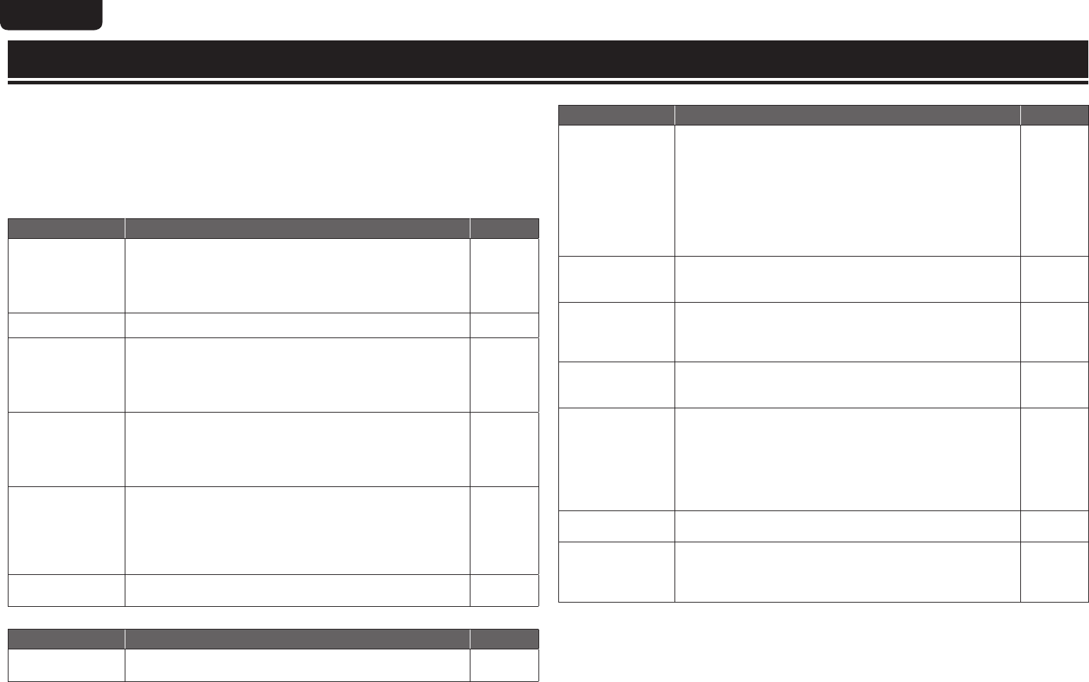
This table shows the speakers that can be used in each surround mode and the surround parameters adjustable in each surround mode.
Symbols in the table
S This indicates the audio output channels or surround parameters that can be set.
D This indicates the audio output channels. The output channels depend on the settings of “Speaker Config.” (vpage61).
Surround mode (vpage31)
Channel output
Surround Parameter (vpage56)
Front
L/R
Center
Surround
L/R
Surround Back
L/R
Front Height L/R Subwoofer
HT-EQ
z3
(vpage56)
DRC
z4
(vpage56)
D. Comp
z5
(vpage56)
LFE
z6
(vpage56)
PURE DIRECT (2channel)
S D
z2
S S
PURE DIRECT (Multi-channel)
S D D D
z1
D
z1
D S S S
DIRECT (2channel)
S D
z2
S S
DIRECT (Multi-channel)
S D D D
z1
D
z1
D S S S
STEREO
S D S S S S
MULTI CH IN
S D D D D S S
DOLBY PRO LOGIC gz S D D D D S S S
DOLBY PRO LOGIC gx S D D D D S S S
DOLBY PRO LOGIC g S D D D S S S
DTS NEO:6
S D D D D S S S
DOLBY DIGITAL
S D D D D D S S S
DOLBY DIGITAL Plus
S D D D D D S S S
DOLBY TrueHD
S D D D D D S S S
DTS SURROUND
S D D D D D S S S
DTS 96/24
S D D D D D S S S
DTS-HD
S D D D D D S S S
DTS Express
S D D D D D S S S
MULTI CH STEREO
S D D D D S S
DOLBY VIRTUAL SPEAKR
S D
z2
S S S
Neural
S D D D D S
Dolby Headphone
S
z1 A signal for each channel contained in an input signal is output as audio.
z2 Only when “Subwoofer Mode” is set to “LFE+Main” (vpage62), sound is output from the subwoofer.
z3 For HD Audio whose sampling frequency of an input signal is more than 96kHz, this sound parameter cannot be set.
z4 This item can be selected when a Dolby TrueHD signal is played.
z5 This item can be selected when a Dolby Digital or DTS signal is played.
z6 This item can be selected when a Dolby Digital or DTS signal or DVD-Audio is played.
84
ENGLISH DEUTSCH FRANÇAIS ITALIANO ESPAÑOL NEDERLANDS SVENSKA
Surround
Surround mode (vpage31)
Surround Parameter (vpage56)
Tonez7
(vpage57)
Audyssey Settings
z11
(vpage57)
M-DAX
z10
(vpage59)
Height Gain
(vpage57)
Panorama
(vpage56)
PRO LOGIC g/gx Music mode only
NEO:6 Music
mode only
Dimension
(vpage56)
C. Width
(vpage56)
C. Image
(vpage56)
MultEQ
®
(vpage57)
Dynamic
EQ
®
z8
(vpage58)
Dynamic
Volume
®
z9
(vpage58)
PURE DIRECT (2 channel)
PURE DIRECT (Multi-channel)
DIRECT (2 channel)
DIRECT (Multi-channel)
STEREO
S S S S S
MULTI CH IN
S S S S
DOLBY PRO LOGIC gz S S S S S S
DOLBY PRO LOGIC gx S S S S S S S S
DOLBY PRO LOGIC g S S S S S S S S
DTS NEO:6
S S S S S S
DOLBY DIGITAL
S S S S
DOLBY DIGITAL Plus
S S S S
DOLBY TrueHD
S S S S
DTS SURROUND
S S S S
DTS 96/24
S S S S
DTS-HD
S S S S
DTS Express
S S S S
MULTI CH STEREO
S S S S S
DOLBY VIRTUAL SPEAKER
S S S S S
Neural
S S S S S
Dolby Headphone
S S
z7 This item cannot be set when “Dynamic EQ” (vpage58) is set to “ON”.
z8 This item cannot be set when “MultEQ” (vpage57) is set to “OFF” or “Manual”.
z9 This item cannot be set when “Dynamic EQ” (vpage58) is set to “OFF”.
z10 This item can be set when the input signal is analog, PCM 48 kHz or 44.1 kHz.
z11 For HD Audio whose sampling frequency of an input signal is more than 96 kHz, this sound parameter cannot be set.
85
Basic versionSimple version Advanced version
ENGLISHDEUTSCHFRANÇAISITALIANOESPAÑOLNEDERLANDSSVENSKA
Information
Surround
n Types of input signals, and corresponding surround modes
This table shows the input signal that can be played in each surround mode. Check the audio signal of the input source then select the surround mode.
Symbols in the table
S This indicates the selectable surround mode.
Surround mode (vpage31)
NOTE
Input signal types and formats
ANALOG
PCM DTS-HD DTS DOLBY DOLBY DIGITAL
LINEAR PCM
(multi ch)
LINEAR PCM
(2ch)
DTS-HD
Master
Audio
DTS-HD
High
Resolution
Audio
DTS
EXPRESS
DTS ES
DSCRT
(With Flag)
DTS ES
MTRX
(With Flag)
DTS
(5.1ch)
DTS 96/24
DOLBY
TrueHD
DOLBY
DIGITAL Plus
DOLBY
DIGITAL EX
(With Flag)
DOLBY
DIGITAL EX
(With no
Flag)
DOLBY
DIGITAL
(5.1/5/4ch)
DOLBY
DIGITAL
(2ch)
DTS SURROUND
DTS-HD MSTR
S
DTS-HD HI RES
S
DTS ES DSCRT6.1
z1z4 S
DTS ES MTRX6.1
z1z4 S
DTS SURROUND
S S S
DTS 96/24
S
DTS (–HD) + PLgx MOVIE z2z4 S S S S S S S
DTS (–HD) + PLgx MUSIC z1z4 S S S S S S S
DTS (–HD) + PLgz z3 S S S S S S S
DTS EXPRESS
S
DTS (–HD) + NEO:6
z1z4 S S S S S S
DTS NEO:6 CINEMA
S S S
DTS NEO:6 MUSIC
S S S
DOLBY SURROUND
DOLBY TrueHD
S
DOLBY DIGITAL+
S
DOLBY DIGITAL EX
z1z4 S S S
DOLBY (D+) (HD) +EX
z1z4 S S
DOLBY DIGITAL
S S S
DOLBY (D) (D+) (HD) +PLgx MOVIE z2z4 S S S S S
DOLBY (D) (D+) (HD) +PLgx MUSIC z1z4 S S S S S
DOLBY (D) (D+) (HD) +PLgz z3 S S S S S
DOLBY PRO LOGIC gx MOVIE z1z4 S S S
DOLBY PRO LOGIC gx MUSIC z1z4 S S S
DOLBY PRO LOGIC gx GAME z1z4 S S S
DOLBY PRO LOGIC gz z3 S S S
DOLBY PRO LOGIC g MOVIE S S S
DOLBY PRO LOGIC g MUSIC S S S
DOLBY PRO LOGIC g GAME S S S
DOLBY VIRTUAL SPEAKER
S S S S S S S S S S S S S S S S
DOLBY HEADPHONE
S S S S S S S S S S S S S S S S
z1 If “Speaker Config.“ – “S.Back“ (vpage62) is set to “None”, this surround mode cannot be selected.
z2 If “Speaker Config.“ – “S.Back“ (vpage62) is set to “1spkr” or “None”, this surround mode cannot be selected.
z3 If “Speaker Config.“ – “F. Height“ (vpage62) is set to “None”, this surround mode cannot be selected.
z4 This surround mode can be selected when “Amp Assign” (vpage61) is set to “Normal”.
86
ENGLISH DEUTSCH FRANÇAIS ITALIANO ESPAÑOL NEDERLANDS SVENSKA
Surround
Surround mode (vpage31)
NOTE
Input signal types and formats
ANALOG
PCM DTS-HD DTS DOLBY DOLBY DIGITAL
LINEAR PCM
(multi ch)
LINEAR PCM
(2ch)
DTS-HD
Master
Audio
DTS-HD
High
Resolution
Audio
DTS
EXPRESS
DTS ES
DSCRT
(With Flag)
DTS ES
MTRX
(With Flag)
DTS
(5.1ch)
DTS 96/24
DOLBY
TrueHD
DOLBY
DIGITAL Plus
DOLBY
DIGITAL EX
(With Flag)
DOLBY
DIGITAL EX
(With no
Flag)
DOLBY
DIGITAL
(5.1/5/4ch)
DOLBY
DIGITAL
(2ch)
MULTI CH IN
MULTI CH IN
S
MULTI CH IN + PLgx MOVIE z2z4 S
MULTI CH IN + PLgx MUSIC z1z4 S
MULTI CH IN + PLgz z3 S
MULTI CH IN + Dolby EX
z1z4 S
MULTI CH IN 7.1
z1z4 S
DIRECT
S S S S S S S S S S S S S S S S
PURE DIRECT
S S S S S S S S S S S S S S S S
MULTI CH STEREO
S S S S S S S S S S S
STEREO
S S S S S S S S S S S S S S S S
NEURAL
S S S
AUTO
S S S S S S S S S S S S S S S S
z1 If “Speaker Config.“ – “S.Back“ (vpage62) is set to “None”, this surround mode cannot be selected.
z2 If “Speaker Config.“ – “S.Back“ (vpage62) is set to “1spkr” or “None”, this surround mode cannot be selected.
z3 If “Speaker Config.“ – “F. Height“ (vpage62) is set to “None”, this surround mode cannot be selected.
z4 This surround mode can be selected when “Amp Assign” (vpage61) is set to “Normal”.
87
Basic versionSimple version Advanced version
ENGLISHDEUTSCHFRANÇAISITALIANOESPAÑOLNEDERLANDSSVENSKA
Information
Relationship between video signals and monitor output
MAIN ZONE MONITOR OUT
Video Convert
Input Signals Output Signals Menu displayed
HDMI COMPONENT VIDEO HDMI COMPONENT VIDEO HDMI COMPONENT VIDEO
1
ON
A A A
Wall paper
A A
Only the menu is
displayed
A
z2
A
2
OFF
A A A
A A A
A
z2
A
3
ON
A A S
VIDEO VIDEO VIDEO
S (VIDEO) A (VIDEO)
z3
A (VIDEO)
4
ON
A
S (1080p)
A
COMPONENT
COMPONENT
A
S (COMPONENT)
A (COMPONENT)
z2
A
5
ON
A
S (1080i ~ 480p)
A
A
A (COMPONENT)
z3
6
ON
A
S (480i/576i)
A
A
7
ON
A
S (1080p)
S
VIDEO
A (COMPONENT)
A (VIDEO)
8
ON
z1
A
S (1080p)
S
S (VIDEO)
9
ON
A
S (1080i ~ 480p)
S
COMPONENT
S (COMPONENT) A (COMPONENT)
z3
10
ON
A
S (480i/576i)
S
11
ON
S A A
HDMI
A A
S (HDMI)
A
z2
A
12
ON
S A S
A
VIDEO
A (VIDEO)
13
ON
S S A
COMPONENT
A
A (COMPONENT)
z2
A
14
ON
S S S
VIDEO
A (VIDEO)
15
OFF
A A S
A A
VIDEO
Only the menu is
displayed
A
z2
A (VIDEO)
16
OFF
A S A
A
COMPONENT
A
A (COMPONENT)
z2
A
17
OFF
A S S
A
VIDEO
A (VIDEO)
18
OFF
S A A
HDMI
A A
A
z2
A
19
OFF
S A S
A
VIDEO
A (VIDEO)
20
OFF
S S A
COMPONENT
A
A (COMPONENT)
z2
A
21
OFF
S S S
VIDEO
A (VIDEO)
S Video signal input present
A No video signal input
z1 When no HDMI monitor is connected or the HDMI monitor’s power is not on
A No video signal output S ( ) Superimposed on the picture indicated in ( ).
A ( ) Only the picture in ( ) is output.
A Neither the picture nor the menu is output.
z2 Only the menu is displayed when no HDMI monitor is
connected or the HDMI monitor’s power is not on.
z3 If an HDMI monitor is not connected or power of an HDMI
monitor is not turned on, the menu is superimposed on a video
image in parenthesis.
• The main zone video conversion function is compatible with the following formats: NTSC, PAL, SECAM, NTSC4.43, PAL-N, PAL-M and PAL-60.
• When SECAM signals of video input are up-converted, the signals are output in PAL format from the S-Video and Video connectors.
• The menu display cannot be superimposed when x.v.Color signals and computer’s resolution (e.g. VGA) are input.
NOTE
• If you operate the menu while playing back 3D video content, the playback video is replaced by the menu screen. The playback video is not displayed behind the menu screen.
• This unit does not show the status display while playing back 3D video content.
88
ENGLISH DEUTSCH FRANÇAIS ITALIANO ESPAÑOL NEDERLANDS SVENSKA
Explanation of terms
A
A2DP
A2DP is one profile of Bluetooth definded for
in-car devices or AV devices that use wireless
communication instead of a cable.
Adobe RGB color / Adobe YCC601 color
Like x.v.Color, each of these color spaces defines
a palette of available colors that is larger than the
traditional RGB color model.
Audyssey Dynamic EQ
®
Audyssey Dynamic EQ solves the problem of
deteriorating sound quality as volume is decreased
by taking into account human perception and room
acoustics. Audyssey Dynamic EQ works in tandem
with Audyssey MultEQ
®
to provide well-balanced
sound for every listener at any volume level.
Audyssey Dynamic Volume
®
Audyssey Dynamic Volume solves the problem of
large variations in volume level between television
programs, commercials, and between the soft and
loud passages of movies. Audyssey Dynamic EQ
is integrated into Dynamic Volume so that as the
playback volume is adjusted automatically, the
perceived bass response, tonal balance, surround
impression, and dialog clarity remain the same.
Audyssey MultEQ
®
Audyssey MultEQ is a room equalization solution
that calibrates any audio system so that it can
achieve optimum performance for every listener
in a large listening area. Based on several room
measurements, MultEQ calculates an equalization
solution that corrects for both time and frequency
response problems in the listening area and also
performs a fully automated surround system setup.
Auto Lip Sync
If you connect the receiver to a TV that supports the
Auto Lip Sync function, it can automatically correct
delay between the audio and video.
B
Bluetooth
Bluetooth is a short-distance wireless
communication technology used for connecting
handheld devices several meters apart. This
enables notebook computers, PDA s, mobile
phones, etc. to connect without a cable for
transmitting audio and data.
D
Deep Color
This technology allows expression of more number
of colors than the conventional 8 bits and can
reproduce colors close to natural ones without color
streak.
Dolby Digital
Dolby Digital is a multi-channel digital signal format
developed by Dolby Laboratories.
A total of 5.1 channels are played: 3 front channels
(“FL”, “FR” and “C”), 2 surround channels
(“SL” and “SR”) and the “LFE” channel for low
frequencies.
Because of this, there is no crosstalk between
channels and a realistic sound field with a “three-
dimensional” feeling (sense of distance, movement
and positioning) is achieved.
A realistic, powerful sense of presence is achieved
when playing movie sources in AV rooms as well.
Dolby Digital EX
Dolby Digital EX is a 6.1-channel surround format
proposed by Dolby Laboratories that allows users
to enjoy in their homes the “DOLBY DIGITAL
SURROUND EX” audio format jointly developed by
Dolby Laboratories and Lucas Films.
The 6.1 channels of sound, including surround back
channels, provide improved sound positioning and
expression of space.
Dolby Digital Plus
Dolby Digital Plus is an improved Dolby Digital signal
format that is compatible with up to 7.1 channels
of discrete digital sound and also improves sound
quality thanks to extra data bit rate performance.
It is upwardly compatible with conventional Dolby
Digital, so it offers greater flexibility in response to
the source signal and the conditions of the playback
equipment.
Dolby Headphone
The Dolby Headphone technology provides a surround
sound listening experience over headphones.
When listening to multichannel content such
as DVD movies over headphones, the listening
experience is fundamentally different than listening
to speakers. Since the headphone speaker drivers
are covering the pinna of the ear, the listening
experience differs greatly from traditional speaker
playback. Dolby utilizes patented headphone
perspective curves to solve this problem and
provides a non-fatiguing, immersive, home theater
listening experience. Dolby Headphone also
delivers exceptional 3D audio from stereo material.
Dolby TrueHD
Dolby TrueHD is a high definition audio technology
developed by Dolby Laboratories, using lossless
coding technology to faithfully reproduce the sound
of the studio master.
This format provides the facility to support up to
8 audio channels with a sampling frequency of
96kHz/24bit resolution and up to 6 audio channels
with a sampling frequency of 192kHz/24bit
resolution. Dolby TrueHD is adopted for applications
that put very high importance on sound quality.
Dolby Pro Logic g
Dolby Pro Logic g is a matrix decoding technology
developed by Dolby Laboratories.
Regular music such as that on CDs is encoded into
5 channels to achieve an excellent surround effect.
The surround channel signals are converted into
stereo and full band signals (with a frequency
response of 20 Hz to 20 kHz or greater) to create
a “three-dimensional” sound image offering a rich
sense of presence for all stereo sources.
Dolby Pro Logic gx
Dolby Pro Logic gx is a further improved version of
the Dolby Pro Logic g matrix decoding technology.
Audio signals recorded in 2 channels are decoded
to achieve a natural sound with up to 7.1 channels.
There are three modes: “Music” suited for playing
music, “Movie” suited for playing movies, and
“Game” which is optimized for playing games.
Dolby Pro Logic gz
Dolby Pro Logic gz introduces a new dimension to
Home Entertainment through the addition of a pair
of front height channels. Compatible with stereo,
5.1-channel and 7.1-channel content, Dolby Pro
Logic gz provides enhanced spaciousness, depth
and dimension to movies, concert video and video
game playback while maintaining the full integrity
of the source mix.
Dolby Pro Logic gz identifies and decodes spatial
cues that occur naturally in all content, directing
this information to the front height channels,
complementing the performance of left and right
surround sound speakers. Content that is encoded
with Dolby Pro Logic gz height channel information
can be even more revealing, with perceptually
discrete height channel information bringing an
exciting new dimension to home entertainment.
Dolby Pro Logic gz, with front height channels is
also an ideal alternative for households that cannot
support the placement of back surround speakers
of a typical 7.1-channel system but may have
bookshelf space available to support the addition of
height speakers.
Dolby Virtual Speaker
Dolby Virtual Speaker is a technology certified
by Dolby Laboratories that creates a virtualized
surround sound experience from two speakers
using a multichannel Dolby Digital source.
Additionally, Dolby Virtual Speaker can simulate
the surround sound effect produced by Dolby Pro
Logic or Dolby Pro Logic g.
Dolby Virtual Speaker retains all the original
Multichannel audio information and provides the
listener with the sensation of being surrounded by
additional speakers.
Downmix
This function converts the number of channels of
surround audio to less number of channels and
plays back.
DTS
This is an abbreviation of Digital Theater System,
which is a digital audio system developed by DTS.
When playing back audio by connecting this system
with a device such as DTS amplifier, accurate sound
field position and realistic sound effect as if you are
in a movie theater can be obtained.
89
Basic versionSimple version Advanced version
ENGLISHDEUTSCHFRANÇAISITALIANOESPAÑOLNEDERLANDSSVENSKA
Information
DTS 96/24
DTS 96/24 is a digital audio format enabling high
sound quality playback in 5.1 channels with a
sampling frequency of 96 kHz and 24 bit quantization
on DVD-Video.
DTS Digital Surround
DTS Digital Surround is the standard digital surround
format of DTS, Inc., compatible with a sampling
frequency of 44.1 or 48 kHz and up to 5.1 channels
of digital discrete surround sound.
DTS-ES™ Discrete 6.1
DTS-ES™ Discrete 6.1 is a 6.1-channel discrete
digital audio format adding a surround back (SB)
channel to the DTS digital surround sound.
Decoding of conventional 5.1-channel audio signals
is also possible according to the decoder.
DTS-ES™ Matrix 6.1
DTS-ES™ Matrix 6.1 is a 6.1-channel discrete digital
audio format inserting a surround back (SB) channel
to the DTS digital surround sound through matrix
encoding. Decoding of conventional 5.1-channel
audio signals is also possible according to the
decoder.
DTS Express
DTS Express is an audio format supporting low bit
rates (max. 5.1 channels, 24 to 256 kbps).
DTS-HD
This audio technology provides higher sound quality
and enhanced functionality than the conventional
DTS and is adopted as an optional audio for Blu-ray
Disc. This technology supports multi-channel, high
data transfer speed, high sampling frequency, and
lossless audio playback. Maximum 7.1-channels are
supported in Blu-ray Disc.
DTS-HD High Resolution Audio
DTS-HD High Resolution Audio is an improved
version of the conventional DTS, DTS-ES and
DTS 96/24 signals formats, compatible with
sampling frequencies of 96 or 48 kHz and up to
7.1 channels of discrete digital sound. High data
bit rate performance provides high quality sound.
This format is fully compatible with conventional
products, including conventional DTS digital
surround 5.1-channel data.
Explanation of terms
DTS-HD Master Audio
DTS-HD Master Audio is a lossless audio format
created by Digital Theater System (DTS). This
format provides the facility to support up to 8 audio
channels with a sampling frequency of 96kHz/24bit
resolution and up to 6 audio channels with a
sampling frequency of 192kHz/24bit resolution.
It is fully compatible with conventional products,
including conventional DTS digital surround
5.1-channel data.
DTS Neural Surround
DTS Neural Surround has been chosen as the
surround sound format for XM Satellite Radio’s
“XM HD Surround”, TV sports broadcasting, 7.1
games, Music Direct Internet streaming as well as
leading FM/HD radio stations. It delivers the rich
envelopment and discrete image detail of surround
sound by unmasking the audio details, typically
lost by other playback modes. Audiences will
experience the deep ambience and subtle details of
movies, music and games.
DTS NEO:6™ Surround
DTS NEO:6™ is a matrix decoding technology
for achieving 6.1-channel surround playback
with 2-channel sources. It includes “DTS NEO:6
Cinema” suited for playing movies and “DTS
NEO:6 Music” suited for playing music.
Dynamic range
The difference between the maximum undistorted
sound level and the minimum discernible level
above the noise emitted by the device.
H
HDCP
When transmitting digital signals between devices,
this copyright protection technology encrypts
the signals to prevent content from being copied
without authorization.
HDMI
This is an abbreviation of High-Definition Multimedia
Interface, which is an AV digital interface that can
be connected to a TV or amplifier. Video signal and
audio signal can be connected using 1 cable.
L
LFE
This is an abbreviation of Low Frequency Effect,
which is an output channel that emphasizes
low frequency effect sound. Surround audio is
intensified by outputting 20 Hz to 120 Hz deep
bass.
M
MAIN ZONE
The room where this unit is placed is called the
MAIN ZONE.
MP3 (MPEG Audio Layer-3)
This is an internationally standardized audio data
compression scheme, using the “MPEG-1” video
compression standard. It compresses the data
volume to about one eleventh its original size while
maintaining sound quality equivalent to a music CD.
MPEG (Moving Picture Experts Group), MPEG-2,
MPEG-4
These are the names for digital compression format
standards used for the encoding of video and audio.
Video standards include “MPEG-1 Video”, “MPEG-
2 Video”, “MPEG-4 Visual”, “MPEG-4 AVC”. Audio
standards include “MPEG-1 Audio”, “MPEG-2
Audio”, “MPEG-4 AAC”.
P
Pairing
Pairing is an operation required for settings to
connect two Bluetooth devices. Pairing enables
Bluetooth devices to access each other.
Protection Circuit
This is a function to prevent damage to components
within the power supply when an abnormality
such as an overload, excess voltage occurs or
temperature for any reason.
In this unit, the power indicator blinks and the unit
enters standby mode when an abnormality occurs.
S
Sampling frequency
Sampling involves taking a reading of a sound wave
(analog signal) at regular intervals and expressing
the height of the wave at each reading in digitized
format (producing a digital signal).
The number of readings taken in one second is
called the “sampling frequency”. The larger the
value, the closer the reproduced sound is to the
original.
Speaker impedance
This is an AC resistance value, indicated in Ω
(ohms). Greater power can be obtained with this
value smaller.
sYCC601 color
Like x.v.Color, each of these color spaces defines
a palette of available colors that is larger than the
traditional RGB color model.
W
WAV (Wave)
WAV is a standard audio format of Windows. The
file size tends to increase, but sound near the
original sound can be maintained.
WMA (Windows Media Audio)
This is audio compression technology developed by
Microsoft Corporation.
WMA data can be encoded using Windows
Media
®
Player Ver.7, 7.1, Windows Media
®
Player
for Windows
®
XP and Windows Media
®
Player 9
Series.
To encode WMA files, only use applications
authorized by Microsoft Corporation. If you use
an unauthorized application, the file may not work
properly.
X
x.v.Color
This function lets HDTVs display colors more
accurately. It enables display with natural, vivid
colors. “x.v.Color” is a Sony registered trademark.
Z
ZONE2
This unit can operate in a room other than the room
where this unit is placed (MAIN ZONE) (ZONE2
playback). The room for ZONE2 playback is called
ZONE2.
90
ENGLISH DEUTSCH FRANÇAIS ITALIANO ESPAÑOL NEDERLANDS SVENSKA
If a problem should arise, first check the following:
1. Are the connections correct?
2. Is the set being operated as described in the user guide?
3. Are the other components operating properly?
If this unit does not operate properly, check the items listed in the table below. Should the problem persist,
there may be a malfunction.
In this case, disconnect the power immediately and contact your store of purchase.
GGeneralH
Symptom Cause/Solution Page
Power does not turn
on.
Check whether the power plug is correctly inserted into the power
outlet.
The protection circuit is active. Disconnect the power plug from
the electric outlet, wait 5 to 10 seconds and then insert it back
into the outlet.
5
4, 89
Display is off. Set “Display” on the menu to something other than “OFF”. 67
The power indicator
is blinking red
in intervals of
approximately 2
seconds.
The temperature inside the unit has risen. Please turn off power
once, and re-apply the power after the temperature has fallen
sufficiently.
Please re-install this unit in a place having good ventilation.
II
II
The power indicator
is blinking red
in intervals of
approximately 0.5
seconds.
Please use speakers which have the specified impedance.
The speaker cable has shorted (is touching). Firmly twist the core
wire in the speaker cable, and then re-connect it to the speaker
terminal.
5
5
After turning on the
power, the power
indicator is blinking
red in intervals of
approximately 0.5
seconds.
This unit amplifier circuit has failed. Turn off the power and please
contact the Marantz service adviser.
Set does not operate
properly.
Reset the microprocessor. 92
GVideoH
Symptom Cause/Solution Page
No picture appears. Check the TV connection.
Set the TV input correctly.
6
7
Troubleshooting
GAudioH
Symptom Cause/Solution Page
Audio is not output. Check the connections for all devices.
Check the speaker connections.
Check whether the audio device power is turned on.
Adjust the master volume.
Cancel the mute mode.
Select a suitable input source.
Select a suitable input mode.
Disconnect the headphones. No sound is output from the speakers
or the PRE OUT connectors when headphones are connected.
5, 14 – 22
5, 36 – 38
24, 44
24, 44
24, 44
55
77
No sound is
produced from
surround speaker.
Check if the surround speakers are connected to the SURROUND
terminals.
No sound is
produced from
surround back
speaker.
Set “Amp Assign” on the menu to “Normal”.
Set “Speaker Config.” “S.Back” on the menu to something
other than “None”.
Set the surround mode to something other than “STEREO”.
61
62
31
No sound is
produced from front
height speaker.
Set “Amp Assign” on the menu to “Normal”.
Set “Speaker Config.” “F.Height” on the menu to something
other than “None”.
61
62
No sound is
produced from
subwoofer.
Check the subwoofer connections.
Turn on the subwoofer’s power.
Set “Speaker Config.” – “Subwoofer” on the menu to “Yes”.
If “Front” and “Center” for “Speaker Config.” are set to “Large”,
and “Subwoofer Mode” is set to “LFE”, no sound may be output
from the subwoofers, depending on the input signal or selected
surround mode.
5, 36 – 38
7
61
61, 62
DTS sound is not
output.
Set “Decode Mode” on the menu to “Auto” or “DTS”. 55
Dolby TrueHD, DTS-
HD, Dolby Digital
Plus audio is not
output.
Make HDMI connections. 16
91
Basic versionSimple version Advanced version
ENGLISHDEUTSCHFRANÇAISITALIANOESPAÑOLNEDERLANDSSVENSKA
Information
GHDMIH
Symptom Cause/Solution Page
No audio is
output with HDMI
connection.
Check the connection of the HDMI connectors.
When outputting HDMI audio from the speakers, set “HDMI
Audio Out” on the menu to “AMP”.
When outputting HDMI audio from a TV, set “HDMI Audio Out”
on the menu to “TV”.
16
64
64
No video is
output with HDMI
connection.
Check the connection of the HDMI connectors.
Set the input source to match the connected HDMI connector.
Check whether the TV is compatible with copyright protection
(HDCP). If connected to a device not compatible with HDCP, video
will not be output correctly.
16
16, 23, 53
15
When the following
operations are
performed on
devices compatible
with HDMI control,
the same operations
occur on this unit.
Power ON/OFF
Switching audio
output devices
Adjust volume
Switch input source
Set “HDMI Control” on the menu to “OFF”. To operate power
only for each device, set “Power Off Control” to “OFF”.
42, 64
GSIRIUS Satellite RadioH
Symptom Cause/Solution Page
“CHECK SIRIUS
TUNER” is displayed.
The SiriusConnect Home Tuner unit is not connected. Check that
the connections are correct.
20
”ANTENNA ERROR”
is displayed.
The antenna is not connected. Check that the connections are
correct.
20
”NO SIGNAL” is
displayed.
The antenna is not connected. Check that the connections are
correct.
”INVALID
CHANNEL” is
displayed.
Channel is not present. Select another channel.
”ACQUIRING
SIGNAL” is
displayed.
The signal cannot be received. Reposition your SiriusConnect
Home Tuner and Home Dock antenna.
Displays while SiriusConnect Home Tuner is connected. Reposition
your SiriusConnect Home Tuner and Home Dock antenna.
”Call SIRIUS”
z
is
displayed.
Channels are not subscribed to. If you subscribe to the channel,
you can receive the channel.
”SUBSCRIPTION
UPDATED” is
displayed.
While updating contract information.
”Enter Lock Code
[ ]” is displayed.
Selected channels are locked. Please insert pass word (4 digits)
into “[ ]”
z After scroll displays “Call 888-539-....” twice, displays “Call SIRIUS”.
GHD Radio receiverH
Symptom Cause/Solution Page
Reception fails, or
there is a lot of noise
or distortion.
Change the antenna orientation or position.
Separate the AM loop antenna from the unit.
Use an FM outdoor antenna.
Separate the antenna from other connection cables.
21
21
21
21
GUSB memory deviceH
Symptom Cause/Solution Page
When a USB
memory device is
connected, “USB” is
not displayed on the
menu.
The set cannot recognize a USB memory device. Check the
connection.
A USB memory device not conforming to mass storage class is
connected. Connect a USB memory device conforming to mass
storage class.
A USB memory device cannot be connected via a USB hub.
19
19
Files on a USB
memory device
cannot be played.
Set the USB memory device format to “FAT16” or “FAT32”. For
details, refer to the USB memory device’s operating instructions.
If the USB memory device is divided into multiple partitions, only
files stored in the top partition can be played.
The file is recorded in an incompatible format. Please record it in
a compatible format.
This unit cannot play back files covered by copyright protection.
The file names
are not displayed
properly (“...”, etc.).
Characters that cannot be displayed on this unit are replaced by
“.” (period).
26
The sound quality is
poor or there is noise
during playback.
The file being played back has a low bit rate.
“Connection Error”
is displayed.
Unable to communicate properly. Turn off the power to this unit,
unplug the USB memory device and then plug it back in.
The USB memory device is not responding. Turn off the power to
this unit, unplug the USB memory device and then plug it back in.
“Overcurrent” is
displayed.
The USB memory device is consuming too much power. When
using a USB portable hard disk that can be powered by an AC
adapter, connect its AC adapter.
92
ENGLISH DEUTSCH FRANÇAIS ITALIANO ESPAÑOL NEDERLANDS SVENSKA
Resetting the microprocessor
Perform this procedure if the display is abnormal or if operations cannot be performed.
When the microprocessor is reset, all the settings are reset to their default values.
Various setting details can be saved and reset on this device. If setting details are saved before returning
to the default values, after returning to the default settings, setting details can be returned to the same
values as before returning to the defaults.
AUTO AUTOBAND
ON/STANDBY ENTER
SURR. MODE
1
When the power is ON, press and hold BAND and ENTER for more than 3 seconds.
After “MEMORY SAVING” is shown on the display, “COMPLETE”is shown to inform you that the
settings have been saved.
2
Turn off the power using ON/STANDBY.
3
Press ON/STANDBY while simultaneously pressing SURROUND MODE and AUTO.
4
Once the display starts ashing at intervals of about 1 second, release the two
buttons.
5
Press and hold BAND and MENU for more than 3 seconds.
After “MEMORY LOAD” is shown on the display, “COMPLETE” is shown to inform you that the
settings have returned to those saved in step 1.
To return all of the settings to the default values, perform steps 2 to 4 without performing step 1.
If in step 3 the display does not flash at intervals of about 1 second, start over from step 1.
GiPodH
Symptom Cause/Solution Page
iPod cannot be
played.
Check the iPod connections.
Switch the input source to “USB”.
Incompatible iPod types cannot be played back.
19
23
19
“Connection Error”
is displayed.
Unable to communicate properly. Turn off the power to this unit,
disconnect the iPod and then reconnect it.
“Not Support” is
displayed.
The iPod connected to the unit is not compatible. Please make
sure the iPod you are connecting is compatible.
The software version of the connected iPod is an old one. Please
update to the latest version.
19
“Connection Error”
is displayed.
The iPod is not responding. Turn off the power to this unit,
disconnect the iPod and then reconnect it.
When an iPod is
connected, “No
Connection” is
displayed.
“No Connection” may display if you connect an iPod that has
only a small amount of charge remaining in its battery to this unit.
Should this occur, charge the iPod before connecting it to this unit.
GM-XPortH
Symptom Cause/Solution Page
Audio is not output
when a wireless
receiver (RX101 is
connected).
Check that the Bluetooth device and Wireless receiver (RX101)
are correctly paired.
GRemote control unitH
Symptom Cause/Solution Page
The set cannot be
operated with the
remote control unit.
Batteries are worn out. Replace with new batteries.
Operate the remote control unit within a distance of about 23 ft /
7 m from this unit and at an angle of within 30°.
Remove any obstacle between this unit and the remote control
unit.
Insert the batteries in the proper direction, checking the q and
w marks.
The set’s remote control sensor is exposed to strong light (direct
sunlight, inverter type fluorescent bulb light, etc.). Move the set
to a place in which the remote control sensor will not be exposed
to strong light.
81
81
81
81
81
93
Basic versionSimple version Advanced version
ENGLISHDEUTSCHFRANÇAISITALIANOESPAÑOLNEDERLANDSSVENSKA
Information
Specifications
n Audio section
Power amplifier
Rated output: Front:
110 W + 110 W (8 Ω, 20 Hz – 20 kHz with 0.08 % T.H.D.)
Center:
110 W (8 Ω, 20 Hz – 20 kHz with 0.08 % T.H.D.)
Surround:
110 W + 110 W (8 Ω, 20 Hz – 20 kHz with 0.08 % T.H.D.)
Surround back / Front height:
110 W + 110 W (8 Ω, 20 Hz – 20 kHz with 0.08 % T.H.D.)
Maximum effective output power: Front:
190 W + 190 W (6 Ω, 1 kHz with 10 % T.H.D.)
Center:
190 W (6 Ω, 1 kHz with 10 % T.H.D.)
Surround:
190 W + 190 W (6 Ω, 1 kHz with 10 % T.H.D.)
Surround back / Front height:
190 W + 190 W (6 Ω, 1 kHz with 10 % T.H.D.)
Output connectors: 6 – 8 Ω (SPEAKER A + B : 8 Ω)
Analog
Input sensitivity/Input impedance: 175 mV/50 kΩ
Frequency response: 10 Hz – 100 kHz — ±3 dB (Source Direct mode)
S/N: 98 dB (IHF–A weighted, Source Direct mode)
n Video section
Standard video connectors
Input/output level and impedance: 1 Vp-p, 75 Ω
Frequency response: 5 Hz – 10 MHz — +1, –3 dB
Color component video connector
Input/output level and impedance: Y (brightness) signal — 1 Vp-p, 75 Ω
P
B / CB signal — 0.7 Vp-p, 75 Ω
P
R / CR signal — 0.7 Vp-p, 75 Ω
Frequency response: 5 Hz – 60 MHz — +0, –3 dB
n HD Radio section [FM] [AM]
(Note: μV at 75 Ω, 0 dBf = 1 x 10
–15
W)
Receiving Range: 87.5 MHz – 107.9 MHz 530 kHz – 1710 kHz
Usable Sensitivity: 1.5 μV (14.8 dBf) 18 μV
S/N (IHF-A): MONO 78 dB
STEREO 68 dB
HD 85 dB 85 dB
Total harmonic Distortion (at 1 kHz): MONO 0.1 %
STEREO 0.2 %
HD 0.02 % 0.02 %
n General
Power supply: AC 120 V, 60 Hz
Power consumption: 650 W
0.2 W (Standby)
3.0 W (CEC standby)
Maximum external dimensions: 440 (W) x 161 (H) x 389 (D) mm
Weight: 11.8 kg
n Remote control unit (RC011SR)
Batteries: R03/AAA Type (two batteries)
For purposes of improvement, specifications and design are subject to change without notice.
94
ENGLISH DEUTSCH FRANÇAIS ITALIANO ESPAÑOL NEDERLANDS SVENSKA
Index
v Numerics
2.1-channel ··················································· 35, 38
3D ······································································· 15
5.1-channel ··················································· 35, 37
6.1-channel ··················································· 35, 36
7.1-channel ··············································· 5, 35, 36
v A
A2DP ···························································· 21, 88
Accessories ·························································· 2
Adjust CH ··························································· 59
Adjusting the master volume ····························· 24
Adobe RGB color / Adobe YCC601 color ··········· 88
AM loop antenna ················································ 21
Amp Assign ························································ 61
Antenna Aiming ·················································· 52
ARC ···································································· 15
Aspect ································································ 54
Audio Adjust ······················································· 56
Audio cable ····························· 6, 17, 18, 19, 20, 22
Audio Delay ························································ 59
Audio Setup ························································ 64
Audio/Video Adjust ············································· 56
Audyssey Auto Setup ····································· 7, 39
Audyssey Dynamic EQ ································· 58, 88
Audyssey Dynamic Volume ························· 58, 88
Audyssey MultEQ ·································· 57, 78, 88
Audyssey Settings ············································· 57
Auto Lip Sync ··············································· 64, 88
Auto Preset ························································ 51
Auto Setup ····················································· 7, 39
v B
Base Curve Copy ················································ 59
Bass ····························································· 57, 65
Bass Setting ······················································· 62
Bi-amp ································································ 38
Bluetooth ······················································ 21, 88
Brightness ·························································· 60
v C
Cable
Audio cable ··························· 6, 17, 18, 19, 20, 22
Coaxial digital cable ···································· 17, 18
Component video cable ······························ 17, 18
HDMI cable ·················································· 6, 16
Optical cable ········································· 17, 19, 20
Speaker cable ···················································· 6
Video cable ··········································· 17, 18, 19
Channel ······························································ 65
Channel Level ··············································· 43, 63
Characters ·························································· 49
Chroma Level ····················································· 60
C.Image ······························································ 56
Coaxial digital cable ······································ 17, 18
Component video cable ······························· 17, 18
Condensation ······················································· 3
Connection
7.1CH INPUT terminal ······································ 22
Antenna ··························································· 20
Blu-ray Disc player ··································6, 16, 17
Cable TV ··························································· 18
CD player ························································· 20
DC OUT (TRIGGER OUT) jacks ························ 41
Digital camcorder ······································· 16, 19
DVD player ··················································16, 17
External power amplifier ·································· 22
Game console ·················································· 16
HDMI ······························································· 15
HD Radio reception ·········································· 21
iPod (USB) ························································ 19
Power cord ························································· 6
Remote control jacks ······································· 40
RS-232C connector ·········································· 41
Satellite tuner ··················································· 18
Set-top box ················································ 16, 18
SIRIUS ····························································· 20
Speaker ························································ 5, 36
TV····························································6, 16, 17
USB memory device ········································ 19
Video cassette recorder ····························· 16, 18
Wireless receiver (RX101) ································ 21
Contrast ······························································ 60
Crossover Frequency ········································· 63
C.Width ······························································ 56
v D
D.Comp ······························································ 56
Decode Mode ···················································· 55
Deep Color ··················································· 15, 88
Dimension ·························································· 56
Direct mode ······················································· 26
Display ·························································· 67, 78
Distance ····························································· 62
DNR ···································································· 60
Dolby
Dolby Digital··············································· 32, 88
Dolby Digital EX ········································· 32, 88
Dolby Digital Plus ······································· 32, 88
Dolby Headphone ······································ 33, 88
Dolby Pro Logic II ············································· 88
Dolby Pro Logic IIx ··········································· 88
Dolby Pro Logic IIz ····································· 35, 88
Dolby TrueHD ············································· 32, 88
Dolby Virtual Speaker ·································33, 88
Downmix ···························································· 88
DRC ···································································· 56
DTS ······························································ 32, 88
DTS 96/24 ·················································· 32, 89
DTS Digital Surround ······································· 89
DTS-ES Discrete 6.1 ·································· 32, 89
DTS-ES Matrix 6.1 ····································· 32, 89
DTS Express ···················································· 89
DTS-HD ······················································ 32, 89
DTS-HD High Resolution Audio ······················· 89
DTS-HD Master Audio ····································· 89
DTS NEO:6™ Surround ····························· 31, 89
DTS Neural Surround ································· 32, 89
Dynamic EQ ······················································· 58
Dynamic range ··················································· 89
Dynamic Volume ················································ 58
v E
Enhancer ···························································· 60
EQ Customize ···················································· 64
Error messages (Auto Setup) ····························· 11
v F
Fader function ···················································· 43
F.Height ······························································ 62
FM indoor antenna ············································· 21
Front A/B (connection) ······································· 37
Front height speaker ···································· 35, 36
Front Panel ························································· 77
v G
GUI ····································································· 66
v H
HDCP ··························································· 15, 89
HDMI ···························································· 15, 89
HDMI 1.4a ·························································· 15
HDMI Audio Out ················································ 64
HDMI cable ···················································· 6, 16
HDMI Control ··············································· 42, 64
HDMI Setup ······················································· 64
HD Radio reception ······································ 21, 29
Headphones ······················································· 77
Height Gain ························································ 57
HPF ···································································· 65
HT-EQ ································································· 56
Hue ····································································· 60
v I
Information ························································· 68
Audio Input Signal ············································ 68
HDMI Information ············································ 68
Preset Channel ················································ 68
Status ······························································· 68
Input Assign ······················································· 52
Input Mode ························································· 55
Input Setup ························································· 50
Input signal ··················································· 32, 85
Inputting characters ··········································· 49
i/p Scaler ····························································· 54
v L
Learn function ···················································· 72
Level Lch ···························································· 65
Level Rch ··························································· 65
LFE ······························································· 56, 89
Listening mode ·················································· 31
Listening position ················································· 8
v M
Macro function ··················································· 74
MAIN ZONE ················································· 45, 89
Manual EQ ························································· 59
Manual Setup ····················································· 61
Master volume display ······································· 66
M-DAX ································································ 59
Menu map ·························································· 47
MP3 ···································································· 89
MPEG ································································· 89
MPEG-4 AAC ······················································ 89
MultEQ ······························································· 57
Mute Level ··················································· 65, 66
M-XPort ······························································ 21
v O
Optical cable ··········································· 17, 19, 20
Option Setup ······················································ 66
Display ····························································· 67
GUI··································································· 66
Setup Lock ······················································· 67
Source Delete ·················································· 66
Trigger Out ······················································· 67
Volume Control ················································ 66
Zone Rename ·················································· 67
95
Basic versionSimple version Advanced version
ENGLISHDEUTSCHFRANÇAISITALIANOESPAÑOLNEDERLANDSSVENSKA
Information
v P
Pairing ································································ 89
Panel lock function ············································· 44
Panorama ··························································· 56
Parameter Check ················································ 11
Parental Lock ······················································ 51
Picture Adjust ····················································· 60
Playback
Blu-ray Disc player ··········································· 24
CD player ························································· 24
Direct ······························································· 33
DVD player ······················································· 24
HD Radio reception ·········································· 29
iPod (USB) ························································ 26
MP3 ································································· 24
MPEG-4 AAC ··················································· 24
Multi-channel ··················································· 31
Pure direct ······················································· 33
SIRIUS ····························································· 27
Stereo ······························································ 33
USB memory device ········································ 24
WMA ······························································· 24
ZONE2 ····························································· 46
Playback Mode ··················································· 55
Power Off Control ·············································· 64
Power On Level ··········································· 65, 66
Preset codes ······················································ 70
Preset Name ······················································ 52
Preset Skip ························································· 51
Presetting radio stations ···································· 29
Progressive Mode ·············································· 54
Protection circuit ················································ 89
v R
Rear panel ·························································· 79
Reference Level Offset ······································ 58
Remote control settings ····································· 68
Remote control unit ····································· 69, 80
Inserting the batteries ······································ 81
Operating AV equipment ································· 69
Operating components ···································· 71
Registering Preset Codes ································ 70
Remote mode ···················································· 26
Rename ······························································ 55
Repeat ································································ 55
Resetting the microprocessor ···························· 92
Resolution ·························································· 54
RGB Range ························································· 64
v S
Sampling frequency ··········································· 89
S.Back ································································ 62
Screensaver ······················································· 66
Selecting the input source ································· 23
Setup Lock ························································· 67
Shuffle ································································ 55
SIRIUS ·························································· 20, 27
Sleep timer ························································· 43
Source Delete ···················································· 66
Source Level ······················································ 55
Speaker
Connect ······················································· 5, 36
Install ··························································· 5, 35
Set up ···························································7, 39
Speaker cable ······················································· 6
Speaker Config. ·················································· 61
Speaker impedance ········································ 5, 89
Speaker Setup ···················································· 61
Standby Source ·················································· 64
Subwoofer setting ················································ 8
Surround back speaker ····························· 5, 35, 36
Surround Mode ············································ 31, 83
Surround Parameter ··········································· 56
Switching the front speakers ····························· 23
sYCC601 color ···················································· 89
v T
Tone ··································································· 57
Tone Control ······················································· 57
Trademark ·························································· 82
Treble ··························································· 57, 65
Trigger Out ························································· 67
Turning off the sound temporarily ······················ 24
Turn off power (standby) ···································· 12
Turn on power ······················································ 7
v V
Video ·································································· 53
Video cable ············································· 17, 18, 19
Video conversion ················································ 14
Video Convert ····················································· 54
Video Mode ························································ 54
Video Select ······················································· 53
Volume Control ·················································· 66
Volume Level ····················································· 65
Volume Limit ················································ 65, 66
v W
WAV ··································································· 89
WMA ·································································· 89
v X
x.v.Color ······················································· 15, 89
v Z
ZONE2 ···················································· 45, 78, 89
Zone Rename ····················································· 67
Zone Setup ························································· 65
PRESET CODE
1
Device select : BD
Blu-ray Disc Player
D
Denon 5034, 5035, 5036
H
Hitachi 5031, 5032, 5033
I
Integra 5013
J
JWC
5014, 5015, 5017, 5018,
5019, 5020
L
LG 5010, 5011
M
Marantz 5000, 5026, 5027
Mitsubishi 5024, 5025
O
Onkyo 5013
P
Panasonic 5001, 5002, 5003
Philips 5004
Pioneer 5005
R
RCA 5012
S
Samsung 5005
Sharp 5028, 5029, 5030
Sony 5007, 5008, 5009, 5016
T
Toshiba 5012
Y
Yamaha 5021, 5022, 5023
Device select : DVD
DVD Player
A
Aiwa 2036, 2037
Apex
2012, 2017, 2018, 2019,
2021, 2034
B
BOSE 2038, 2039, 2063
D
Denon 2047, 2048
F
Funai 2049
G
GE 2009, 2020, 2029, 2033
H
Harman Kardon 2061
Hitachi 2008, 2012, 2031
J
JVC
2006, 2010, 2040, 2041,
2042, 2043
K
Kenwood 2053, 2054
Koss 2058
M
Magnavox 2007, 2011, 2023, 2025
Marantz 2025, 2065
Marantz (Blu-ray) 2064
Mitsubishi 2011, 0215
O
Onkyo 2062
Oritron 2009, 2030
P
Panasonic 2003, 2015, 2016, 2055
Philips 2007, 2011, 2058
Pioneer 2002, 2014, 2056
Proscan 2009, 2020, 2032
R
RCA
2005, 2009, 2020, 2035,
2057
S
Sampo 2041
Samsung
2008, 2012, 2022, 2024,
2027
Sanyo 2050, 2052
Sharp 2044, 2045
Sherwood 2051
Sony 2001, 2013, 2059
T
Toshiba 2004, 2008, 2026, 2028
Y
Yamaha 2046, 2060
Z
Zenith 2010
Device select : SAT
Satellite Receiver
A
Alphastar 4027
Amstrad 4046, 4047, 4050
Atsky 4048
B
B Sky B 4021, 4045, 4046
C
Chaparral 4039
D
DIRECTV 4001, 4016, 4044
DISH Network 4030
Drake 4026
E
Echostar
4007, 4017, 4018, 4019,
4020, 4062, 4063, 4064
Eurosky 4047, 4056
Express Vu 4017
F
Foxtel 4051
Freesat 4056
Fujitsu 4025
G
GE 4002, 4008, 4009
General Instruments 4036, 4037
Gradiente 4044, 4057
H
Hitachi 4001, 4015
Hughes 4001, 4016
Humax
4049, 4050, 4051, 4052,
4053
J
Janeil 4025
JVC 4017
M
Mitsubishi 4001
N
Nokia 4058, 4059, 4060, 4061
O
Optima 4048
P
Panasonic 4004, 4010
Philips 4031, 4035, 4044, 4057
Proscan 4002, 4008, 4009, 4011
R
Radio Shack 4036, 4037
RCA 4002, 4008, 4009, 4029
Realistic 4040
Rural Cable 4036
S
Samsung
4022, 4027, 4042, 4043,
4050, 4054, 4055
Schneider 4041, 4043
SKY 4044, 4045, 4057
Skyplus 4048
Skysat 4041, 4047, 4056
Sony
4003, 4012, 4014, 4065,
4066, 4067
Star Choice 4032
Star Trak 4024
STS 4038
SuperDish 4028
T
Teac 4049
Thomson 4046, 4056
Toshiba 4001, 4034
U
Uniden 4005, 4006, 4013
Universum 4056
V
Video Pall 4025
Z
Zenith 4023, 4025, 4033
Device select : TV
Television
A
Acer 1141
Admiral 1002, 1009, 1089
Aiko 1059
Aiwa 1117, 1118
Akai 1001
Amtron 1023
Anam 1113
Anam National 1023, 1069, 1092
AOC 1003, 1024, 1049, 1127
Audiovox 1023
B
Bell & Howell 1009, 1025
Benq 1104, 1142
Broksonic 1003, 1097, 1098, 1113
C
Celebrity 1001
Citizen
1003, 1013, 1023, 1026,
1059, 1063
Colortyme 1003, 1043
Contec 1113
Contec/Cony 1023, 1045, 1047
Craig 1020, 1022, 1023, 1113
Crown 1023, 1067
Curtis Mathes
1003, 1013, 1025, 1026,
1062, 1103, 1110
D
Daewoo
1003, 1013, 1024, 1035,
1036, 1059, 1084, 1101
Daytron 1003, 1013, 1016
Dimensia 1103, 1110
Dumont 1003, 1010, 1153
E
Electroband 1001
Electrohome 1001, 1003, 1069, 1133
Emerson
1003, 1013, 1015, 1020,
1021, 1022, 1023, 1025,
1038, 1044, 1045, 1048,
1055, 1061, 1094, 1096,
1099, 1101, 1113
Envision 1003
F
Fisher 1025, 1051, 1091, 1160
Fujitsu 1038, 1124, 1125, 1155
Funai 1023, 1038, 1113
G
Gateway 1150
GE
1003, 1018, 1022, 1046,
1054, 1069, 1085, 1103,
1110, 1113, 1133, 1136,
1153
Goldstar
1003, 1013, 1024, 1030,
1045, 1080, 1100
1112, 1154
H
Hallmark 1003
Hisense 1116
Hitachi
1003, 1012, 1031, 1032,
1037, 1041, 1045, 1047,
1065, 1068, 1082, 1088,
1094, 1139, 1140, 1145,
1159
I
Infi nity 1067
J
Janeil 1134
JBL 1067
JC Penney
1003, 1013, 1018, 1019,
1024, 1026, 1046, 1047,
1054, 1063, 1083, 1085,
1100, 1103, 1110, 1112,
1133, 1154
Jensen 1003
JVC
1028, 1029, 1045, 1047,
1050, 1060, 1065
K
Kawasho 1001, 1003
Kenwood 1003
Kloss Novabeam 1023, 1056, 1057, 1134
KTV
1013, 1023, 1033, 1034,
1073, 1099, 1113
L
LG 1024, 1030
M
M.Wards 1002, 1009, 1038
Magnavox
1003, 1052, 1053, 1056,
1057, 1063, 1067, 1081,
1106
Marantz 1003, 1031, 1067, 1122
Mitsubishi
1003, 1024, 1051, 1115,
1122, 1133
Motorola 1014, 1069
N
NEC
1003, 1012, 1024, 1043,
1069
NET-TV 1137, 1150
O
Orion 1020, 1096
P
Panasonic
1017, 1067, 1069, 1095,
1111
Philips
1003, 1011, 1045, 1052,
1054, 1056, 1057, 1058,
1063, 1067, 1069, 1106
Pioneer
1003, 1018, 1037, 1070,
1071, 1094, 1145, 1147,
1149
Plasmsync 1135
Portland 1003, 1013, 1024, 1059
Price Club 1026
Prism 1018
Proscan
1004, 1005, 1006, 1007,
1008, 1085, 1103, 1110
Proton 1003, 1045
Q
Quasar
1010, 1069, 1073, 1111,
1153
R
Radio Shack
1003, 1013, 1015, 1023,
1024, 1025, 1045, 1100,
1103, 1110, 1113
RCA
1003, 1004, 1005, 1006,
1007, 1008, 1014, 1024,
1049, 1069, 1075, 1079,
1085, 1087, 1088, 1093,
1094, 1101, 1103, 1110,
1113, 1153
Realistic
1013, 1015, 1023, 1025,
1045, 1100, 1103, 1110
Runco 1010, 1153
S
Sampo 1150
Samsung
1003, 1013, 1024, 1026,
1040, 1045, 1062, 1078,
1083, 1090, 1100, 1105,
1114, 1120, 1121, 1146,
1148, 1157
Sansui 1119
Sanyo
1003, 1025, 1051, 1072,
1077, 1091, 1156, 1157,
1158
Sharp
1003, 1013, 1014, 1015,
1045, 1055, 1064, 1066,
1076, 1089, 1123
Signature 1009
Sony 1001, 1102, 1108
Soundesign
1003, 1023, 1038, 1063,
1113
Starlite 1023
Supre-Macy 1134
Sylvania
1003, 1039, 1042, 1052,
1053, 1056, 1057, 1063,
1067, 1089, 1151
Symphonic 1023, 1039, 1044
T
Tandy 1014
Tatung 1069
Technics 1018
Techwood 1003, 1018
Teknika
1003, 1009, 1013, 1023,
1024, 1026, 1038, 1045,
1047, 1059, 1063, 1111,
1113
Telecaption 1074
Toshiba
1003, 1019, 1025, 1026,
1042, 1074, 1098, 1107,
1111, 1135, 1136
Totevision 1013
U
Universal 1046, 1054
V
Video Concepts 1113
List of preset codes / Liste de codes préréglés / Lista de códigos pre-ajustados
PRESET CODE
2
Viewsonic
1006, 1022, 1109, 1128,
1129, 1130, 1131, 1138,
1143, 1145, 1150
W
Wards
1003, 1009, 1015, 1024,
1038, 1044, 1046, 1052,
1054, 1056, 1057, 1067,
1086, 1103, 1110
White
Westinghouse
1001, 1101
Y
Yamaha 1003, 1024
Z
Zenith
1003, 1009, 1010, 1132,
1144, 1153
Device select : CD
CD Player
A
AIWA 3001, 3002, 3003
AKAI 3004, 3005, 3006
AUDIO 3007
AUDIO LABS 3008
C
CALIFORNIA 3008
CARVER 3010, 3011, 3009
CASIO 3012, 3020
CURTIS 3020, 3012
D
DENON 3013
E
EMERSON 3014
F
FISHER
3011, 3015, 3016, 3017,
3018
G
GE 3019
GENEXXA 3014, 3021, 3020
H
HARMON 3022, 3023, 3051
HITACHI 3020
I
INKEL 3024
J
JC PENNEY 3012, 3020, 3025
JVC 3026, 3027
K
KARDON 3022, 3051, 3023
KRELL 3010
L
LUXMAN 3035, 3036, 3037, 3038
LX I 3012, 3020, 3014
M
MAGNAVOX 3010, 3039, 3040
MARANTZ 3010, 3041, 3042, 3043
MATHES 3012, 3020
MCS 3012, 3020
MGA 3023
MISSION 3010
MITSUBISHI 3023, 3044
N
NAD 3034, 3045
NAKAMICHI 3046, 3047, 3048
NEC MCS 3025
NIKKO 3007, 3016
O
ONKYO
3049, 3050, 3051, 3052,
3055, 3102, 3103
OPTIMUS
3011, 3014, 3020, 3028,
3053, 3054, 3056, 3057,
3058, 3059
P
PANASONIC 3008, 3060, 3061
PHILIPS 3009, 3010, 3010, 3040
PIONEER
3020, 3021, 3062, 3063,
3064
Q
QUASAR 3008
R
RCA
3011, 3014, 3065, 3066,
3067, 3068, 3069
REALISTIC
3011, 3014, 3020, 3042,
3054, 3057
ROTEL 3010
RS ORIGINAL 3070
S
SAE 3010, 3083
SAMSUNG 3071
SANSUI 3014, 3068, 3072, 3073
SANYO
3011, 3018, 3074, 3075,
3076
SCOTT 3014
SEARS
3012, 3014, 3020, 3028,
3042
SHARP 3028, 3042, 3077
SHERWOOD
3042, 3056, 3070, 3078,
3024
SHURE 3025
SONY
3039, 3079, 3080, 3081,
3082, 3097, 3098, 3099,
3100, 3101
SYLVANIA 3010
SYMPHONIC 3083
T
TEAC
3016, 3042, 3057, 3083,
3084, 3085, 3086
TECHNICA
3007, 3008, 3061, 3087,
3088
THETA DIGITAL 3040
TOSHIBA 3045
V
VICTOR 3026
Y
YAMAHA
3007, 3089, 3090, 3091,
3092
Z
ZENITH
3016, 3093, 3094, 3095,
3096
348.5 (13 11/16)
146.5 (5 3/4)
22.5
(15/16)
17.5
(11/16)
14.5
(5/8)
389.0 (15 3/8)
161.0 (6 3/8)
440.0 (17 3/8)
Unit : mm (in)
Dimensions / Dimensions / Dimensions
D&M Holdings Inc.
Printed in China 5411 10482 024M
8

Hulp nodig? Stel uw vraag in het forum

Spelregels
1

Forum

Marantz-SR6005
  • waar zit de aansluiting subwoofer bij markants 6005 Gesteld op 11-11-2021 om 15:05

    Reageer op deze vraag Misbruik melden
  • Beste mensen

    Ik wil graag mijn Thorens platenspeler aansluiten en heb ook een NAD voorversterker hoe doe ik dat op een Marantz SR6005 Gesteld op 12-2-2016 om 09:49

    Reageer op deze vraag Misbruik melden
    • De sr 6005 heeft geen ingang voor een platenspeler.
      In dat geval is een voorversterkertje nodig bv de Nad preamp pp21.
      Je sluit de pick-up op de ingang aan van de pre-amp .Vervolgens sluit je een kabel aan op de uitgang van de pre-amp;deze sluit je vervolgens aan op een van de audio video ingangen van de receiver.. Geantwoord op 24-2-2016 om 15:51

      Waardeer dit antwoord Misbruik melden

Misbruik melden

Gebruikershandleiding.com neemt misbruik van zijn services uitermate serieus. U kunt hieronder aangeven waarom deze vraag ongepast is. Wij controleren de vraag en zonodig wordt deze verwijderd.

Product:

Bijvoorbeeld antisemitische inhoud, racistische inhoud, of materiaal dat gewelddadige fysieke handelingen tot gevolg kan hebben.

Bijvoorbeeld een creditcardnummer, een persoonlijk identificatienummer, of een geheim adres. E-mailadressen en volledige namen worden niet als privégegevens beschouwd.

Spelregels forum

Om tot zinvolle vragen te komen hanteren wij de volgende spelregels:

Belangrijk! Als er een antwoord wordt gegeven op uw vraag, dan is het voor de gever van het antwoord nuttig om te weten als u er wel (of niet) mee geholpen bent! Wij vragen u dus ook te reageren op een antwoord.

Belangrijk! Antwoorden worden ook per e-mail naar abonnees gestuurd. Laat uw emailadres achter op deze site, zodat u op de hoogte blijft. U krijgt dan ook andere vragen en antwoorden te zien.

Abonneren

Abonneer u voor het ontvangen van emails voor uw Marantz SR6005 bij:


U ontvangt een email met instructies om u voor één of beide opties in te schrijven.


Ontvang uw handleiding per email

Vul uw emailadres in en ontvang de handleiding van Marantz SR6005 in de taal/talen: Engels als bijlage per email.

De handleiding is 23,33 mb groot.


U ontvangt de handleiding per email binnen enkele minuten. Als u geen email heeft ontvangen, dan heeft u waarschijnlijk een verkeerd emailadres ingevuld of is uw mailbox te vol. Daarnaast kan het zijn dat uw internetprovider een maximum heeft aan de grootte per email. Omdat hier een handleiding wordt meegestuurd, kan het voorkomen dat de email groter is dan toegestaan bij uw provider.

Stel vragen via chat aan uw handleiding

Stel uw vraag over deze PDF

Andere handleiding(en) van Marantz SR6005

Marantz SR6005 Gebruiksaanwijzing - Nederlands - 96 pagina's

Marantz SR6005 Gebruiksaanwijzing - Français - 104 pagina's

Marantz SR6005 Gebruiksaanwijzing - Espanõl - 104 pagina's


Uw handleiding is per email verstuurd. Controleer uw email

Als u niet binnen een kwartier uw email met handleiding ontvangen heeft, kan het zijn dat u een verkeerd emailadres heeft ingevuld of dat uw emailprovider een maximum grootte per email heeft ingesteld die kleiner is dan de grootte van de handleiding.

Er is een email naar u verstuurd om uw inschrijving definitief te maken.

Controleer uw email en volg de aanwijzingen op om uw inschrijving definitief te maken

U heeft geen emailadres opgegeven

Als u de handleiding per email wilt ontvangen, vul dan een geldig emailadres in.

Uw vraag is op deze pagina toegevoegd

Wilt u een email ontvangen bij een antwoord en/of nieuwe vragen? Vul dan hier uw emailadres in.


Info