1Area of application ....................................................................................................................................................................................................................... 3
1.1Use in accordance with BGR 228 .................................................................................................................................................................................... 3
a)CO2 sensor unit .............................................................................................................................................................................................................. 4
b)CO2 warning unit ............................................................................................................................................................................................................ 4
c)AM / AM PLUS add-on module ....................................................................................................................................................................................... 4
e)Switching unit ................................................................................................................................................................................................................. 5
f)Signal unit ....................................................................................................................................................................................................................... 5
i)Mode of operation ......................................................................................................................................................................................................... 6
a)Installation in a dispensing system ................................................................................................................................................................................. 7
b)CO2 CONTROL add-on module installation for a CO2 cooling system ............................................................................................................................ 7
2.1General notes in accordance with BGR 228 ................................................................................................................................................................... 8
2.3CO2 sensor unit installation ........................................................................................................................................................................................... 9
2.4Installing the CO2 warning unit (PA)............................................................................................................................................................................... 9
2.5Setting the geographic height ......................................................................................................................................................................................10
2.6Installing the AM / AM PLUS add-on module ...............................................................................................................................................................11
2.7Installing the distributor ...............................................................................................................................................................................................11
2.8Connecting cables to the distributor ............................................................................................................................................................................12
2.9.1Switching unit ...............................................................................................................................................................................................................12
2.9.2Signal unit .....................................................................................................................................................................................................................12
2.9.4Alarm unit horn/light....................................................................................................................................................................................................13
3.3Re-commissioning after swapping-out .........................................................................................................................................................................14
3.4Instruction for the operator .........................................................................................................................................................................................14
3.5Documentation in the dispensing log ...........................................................................................................................................................................15
4.2Replacing the CO2 sensor unit......................................................................................................................................................................................15
5Technical data ............................................................................................................................................................................................................................16
5.1CO2 CONTROL sensor unit ............................................................................................................................................................................................16
5.2CO2
CONTROL PA warning unit ....................................................................................................................................................................................16
5.3AM / AM PLUS add-on modules ...................................................................................................................................................................................17
5.4Signal unit .....................................................................................................................................................................................................................17
5.5Switching unit ...............................................................................................................................................................................................................18
5.6Accessories / spare parts ..............................................................................................................................................................................................18
6Measures in the event of a malfunction/gas alarm ....................................................................................................................................................................18
8Instructions for the prevention of hazards due to CO
2
gas ........................................................................................................................................................19
8.1Code of conduct ...........................................................................................................................................................................................................19
These assembly and operating instructions contain all of the information necessary for the installation, commissioning and maintenance of the CO2 CONTROL
CO
2
gas detection system.
0.1Safety information
Symbol Definition
1Area of application
1.1Use in accordance with BGR 228
The CO2 CONTROL gas detection system was designed in accordance with the requirements of the former TRSK 313 (Technical Requirements for Gas Detection
Devices), the current DIN6653-2 and the former TRSK 403 (Requirements for Installation, Operation and Repair), and today in accordance with BGR 228, and
complies with all statutorily required functions. However, this is only applicable to CO2 CONTROL security systems which are calibrated for 1.5% CO2 preliminary
alarm and 3% CO2 main alarm signals!
Since 07/05/1996, the legislative authority requires special protective measures in order to be able to prevent hazards due to gas leaks (Betr.Sich.V.).
A specific protective measure requires premises 1.5 m below ground level to be fitted with permanent ventilation/floor extraction, or alternatively, a gas
detection system. Walk-in cold chambers must always be secured, regardless of their installation location!
1.2Use in refrigeration systems with CO
2
coolant
Special safety system requirements, in CO2 CONTROL PA, CO2
CONTROL AMand CO2 CONTROL AM PLUS versions, are installed for the monitoring of
refrigeration systems (DIN EN 378) with CO
2
coolant, mainly in the food trade and processing industries.
Normally, the machine room, freezers, cold chambers and partially refrigerated access ways are monitored. In supermarkets, staff rooms are also monitored
when these come into contact with the coolant lines.
1.3System description
Method of measurement:
CO
2
is detected using an infra-red measurement system in the sensor unit.
System structure:
As a base system, the CO2 CONTROL basic package consists of a sensor unit, a warning unitand a distributor. Where multiple spaces are at risk, the system can
be expanded to include a second sensor unit.
Optionally, the system can also be expanded to up to 2 devices (any combination of signal units / switching units).
Caution! Observe the instructions in the manual!
CO2 CONTROL - assembly and operating instructions
-4-
a)CO2 sensor unit
The sensor unit is installed in the hazard area and is connected by means of a distributor to the warning unit. A visual and audible warning on the sensor unit
enables warnings even in the hazard area itself.
b)CO2 warning unit
The warning unit is installed in front of the hazard area and warns individuals wishing to enter the area of a potential hazard.
c)AM / AM PLUS add-on module
The add-on module includes the PA warning unit and enables operating states to be forwarded internally as 230 V / 50 Hz or via a floating external power
supply. The AM PLUS variant features a large integrated alarm light with horn and additional alarm equipment can be connected. The basic functions are
identical to those of the CO2 CONTROL standard variant.
Caution!
100 dB
acoustic
signal
CO2 CONTROL - assembly and operating instructions
-5-
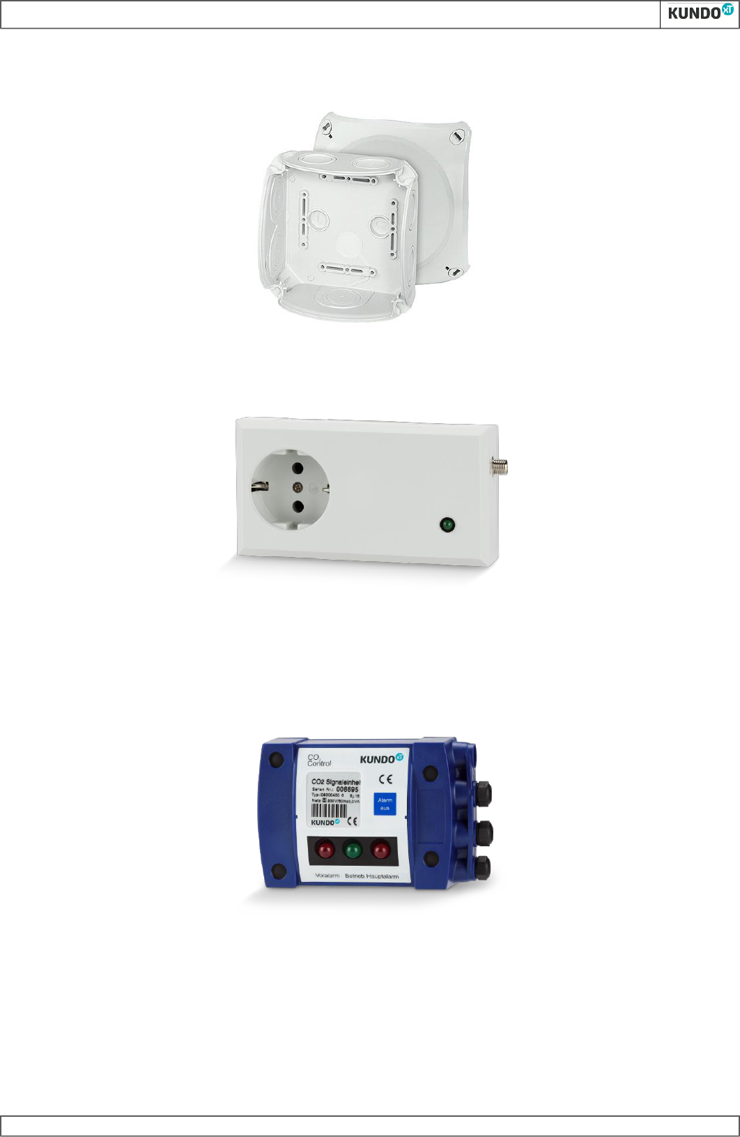
d)Distributor
The distributor and control lines connect all of the components into a system.
e)Switching unit
The switching unit canactuate power consumption devices, such as fans or external signal devices, in the event of an alarm.
f)Signal unit
The signal unit is connected to the warning unit (central unit) and is used when multiple entry areas must be secured in the hazard area (additional cellar
entrances, doors). The signal unit can also be used as a monitoring display in the counter area.
The signal unit has no central function, but merely serves as an additional visual/audible indicator unit.
CO2 CONTROL - assembly and operating instructions
-6-
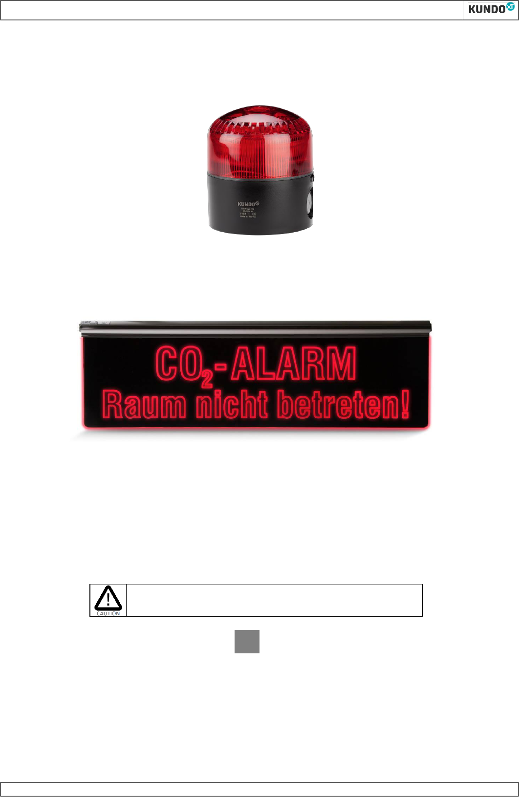
g)Alarm unit
The 230 V version of the alarm unit is used to provide additional visual and audible alarms in hazard areas as well as in the entrances to hazard areas.
When used in combination with the CO2 CONTROL AM version, these can be directly connected, supplied with power, and their alarms switched off directly on
the add-on module.
h)Luminous warning panel
The 230 V and 24 V versions of the luminous warning panel is used to provide additional visual alarms in the entrances to hazard areas.
i)Mode of operation
The sensor unit determines the CO
2
content of the air and transmits the measured values to the warning unit. CO2 CONTROL has 2 alarm thresholds.
Under normal operating conditions, the green power light is lit.
Pre-alarm:
The pre-alarm is triggered when a CO
2
content of 1.5% is exceeded. An intermittent warning sound and the flashing red LED on the warning unitand sensor unit
indicate a hazard.
Main alarm:
When the CO
2
content increases above 3%, the main alarm is triggered. This is indicated by means of a continuous sound and continuously lit red LED on the
warning unitand sensor unit.
When the main alarm is triggered, no further access to the hazard area must be allowed!
The hazard can only be eliminated by switching on a fixed or mobile air extraction unit or
by the fire brigade!
All audible signals can be switched off by pressing the Alarm off key.
In the event of a pre-alarm, the visual alarm indicator switches off automatically once the gas concentration drops to normal levels. In the event of a main alarm,
the visual alarm indicator can only be switched off by once again pressing the key if the CO
2
gas concentration is lower than 1.5%. If the gas concentration is
between 1.5% and 3%, the indicator will switch from continuous to flashing light.
In the event of a system fault due to a cable break, short-circuit, sensor failure or other cause, the yellow indicator (Fault) on the warning unitand sensor unit
and/or the green flashing LED on the signal unit will flash and an audible signal will sound; these can be acknowledged and/or cancelled by pressing the key. The
yellow indicator will remain lit until the system fault is eliminated and acknowledged by once again pressing the key.
Alarm
off
CO2 CONTROL - assembly and operating instructions
-7-
When used in freezer units, the sensor units must be adjusted to the ambient temperature
before commissioning. Otherwise, undefined fault messages will be shown, which will
disappear once the sensor units are acclimatised. Only then will your system be ready to run!
1.4System configuration
The sensor unit is installed in all spaces at risk (cellars/cold rooms, storage areas and holding spaces for gas cylinders, freezer units, etc.).
The warning unit/add-on module must be installed directly in front of the hazard area.The warning unitand sensor unit are connected to each other by means
of a distributor.
The switching unit switches on an extraction unit or other power consumption device in the event of an alarm. The signal unit secures the hazard area from
further access.
The warning unit must be installed immediately in front of the entrance to the hazard
area! Where there are multiple entrances to the hazard area, a signal unit and/or
additional alarm unit must be installed in front of each additional entrance!
a)Installation in a dispensing system
b)CO2 CONTROL add-on module installation for a CO2 cooling system
In grocery stores, cold rooms, freezer rooms and machine rooms are mostly secured with CO2 CONTROL AM. Alarm and fault messages are controlled at the
refrigeration control system. Alarms are acknowledged directly in a decentralised manner on the add-on module.
Counter
Additional signal unit can be installed directly on the counter
as an indicator. (optional)
Warning unit
Distributor
Cellar
Door
Sensor unit 2
Holding spaces
CO2
bottles
Distributor
Switching unit
Sensor unit 1
30 cm
Cellar entrance
Supply of the CO2 CONTROL unit by
superordinated control
Superordinated control
1.
Cooling unit
2.
Cooling unit
3.
Cooling unit
4.
Cooling unit
5.
Cooling unit
6.
Cooling unit
CO2 CONTROL - assembly and operating instructions
-8-
2Assembly
2.1General notes in accordance with BGR 228
The gas detection system installer is responsible and therefore liable for the correct
installation and handover of the equipment.
Gas detection devices (equipment requiring special monitoring) may only be planned,
installed and maintained by specialist personnel.
To ensure safe operation, only ancillary components approved by KUNDOxT may be
connected to the CO2 CONTROL safety system.
BGR 228 /DIN 6653-2 stipulates all of the statutory measures and the state of the art for the installation and operation of gas detection equipment in dispensing
systems.
DIN EN 378 refers to the state of the art for the application, operation and functional checking of gas detection devices in the refrigeration field.
The rules therein must normally be observed and complied with. All further measures for the installation/assembly of the CO2 CONTROL gas detection system
are given in the sections below.
Note: Please observe the separate assembly instructions for CO2 CONTROL AM!
2.2System design
The overview identifies the possible system component connections via the distributor. The PA version has a second control line (5-wire) to the building
control/control system.
The sensor unit may only be operated in an upright, assembled condition (see Fig.).
The CO2 CONTROL version is supplied with power through the control line from the building control/control system. An input for power supply and control is
available for additional alarm units.
CO2 CONTROL AM / AM PLUS basic package
CO2 CONTROL PA basic package
Expansion with a second sensor unit
Signal unit
to secure further
entrances/doors
Expansion with a second sensor unit
Signal unit
to secure further
entrances/doors
- control line 3m
- control line variabel
Sensor unit 1
Sensor unit 2
Distributor
Switching unit
Distributor
Distributor
Warning unit
potential free
outputs
(PA, MA, Fault and Operation)
- control line 3m
- control line variabel
Switching unit
Sensor unit 1
Sensor unit 2
Distributor
Distributor
Distributor
Supply 230V, control outputs
(PA, MA, Sum, Fault and Operation)
Connection
for an
external
Alarm unit
AM /
AM Plus
CO2 CONTROL - assembly and operating instructions
-9-
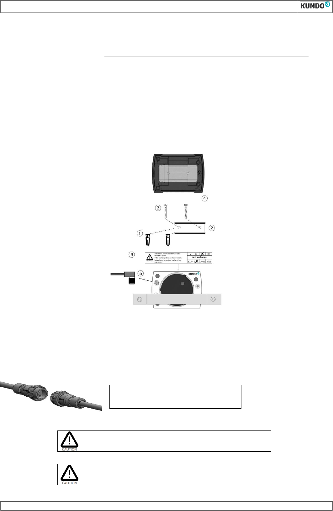
2.3CO2 sensor unit installation
Select an installation point in such a way that:
- The sensor unit is not exposed to direct draughts. When used in freezer rooms, the sensor unit must first be acclimatised to the ambient temperature.
- The sensor unit reaches the deepest point in the monitoring area
- It is approx. 30 cm away from the floor
- The sensor unit can be installed on a vertical wall
- The sensor unit is protected from mechanical impacts as far as possible
Drill two holes at a distance of 40 mm with an 8 mm drill and insert the dowels (1). Use the screws (3) to screw the DIN rail (2) to the wall and tighten the screws.
Position the lower part of the sensor unit (4) housing onto the rail from above, and press the sensor unit downward until the clamping mechanism snaps in with
an audible click. The sensor unit can be removed again from the DIN rail by pulling the terminal snap-in mechanism.. Secure the control cable to the sensor unit
using the plug (5). Tighten the union nut on the plug.
A maintenance plate is mounted on the sensor unit. Mark this with the next replacement date with a ballpoint pen or screwdriver. This should be replaced every
4 years of operation.
CO2 sensor unit installation
2.4Installing the CO2 warning unit (PA)
As a precondition for installation, a qualified electrician must first of all install a power distributor or socket at ceiling height in the entrance area.
The warning unit is fitted with a 2.5 m long power cable and plug. The warning unit can be connected to the mains power either permanently, or via a plug. You
must make sure that a continuous power supply can be ensured.
The PA warning unit can only be permanently connected to a 230 V / 50 Hz power supply and comes with a plug for the necessary "one-man initialisation".
A permanent installation may only be performed by a qualified technician (electrician)!
The warning unit must be installed immediately in front of the danger area!
Disconnect the PA warning unit during initialisation and
when switching off the power.
CO2 CONTROL - assembly and operating instructions
-10-
Select the mounting point in such a way that a system warning cannot be ignored before entering the danger area.
Please only use sockets and circuits which are constantly in operation and which cannot be
switched on and off as required!
The PA version provides 4 floating outputs for switching. Pre-alarm, main alarm, operation and fault messages can be forwarded.
CO2 CONTROL PA version
Connection and colour layout of the floating outputs
CO2 CONTROL AM / AM PLUS versions
See CO2 CONTROL AM / AM PLUS assembly instructions
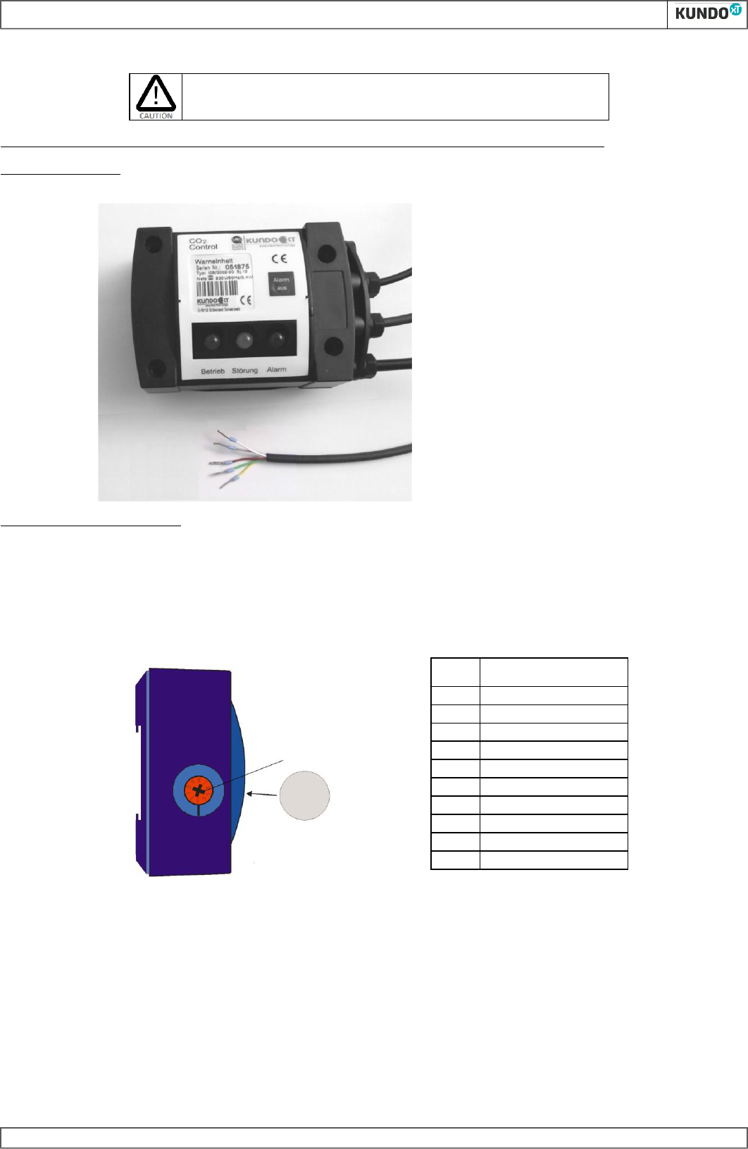
2.5Setting the geographic height
On the side of the warning unit, there is a rotary switch for setting the location height at which the detection system is installed. Ask the operator the height of
the restaurant above sea level. Check this against the height range given in the table and set the position (0...9) of the switch so that the number on the switch is
above the marking on the housing.
Level
Height [m]
above sea level
0
0 .. 250
1
250 .. 500
2
500 .. 750
3
750 .. 1000
4
1000 .. 1250
5
1250 .. 1500
6
1500 .. 1750
7
1750 .. 2000
8
2000 .. 2250
9
2250 .. 2500
An input voltage for the PA outputs of up to
max. 60 VDC / 125 VAC at max. 0.5 A can be
applied.
white: Input 24V AC/DC
grey: Pre-alarm
brown: Main alarm
green: Operation
yellow: Fault
Setting of the
altidude above sea
level according to
the table
After setting the height,
the housing on the rotary
switch must be sealed
with the attached
transparent adhesive film!
CO2 CONTROL - assembly and operating instructions
-18-
5.5Switching unit
Technical data
Rated voltage:
Rated current / rated output:
230 V / 50 Hz
10 mA / 6 W
Max. switching current:
16 A
Control line:
RS485 bus connection
3 m control line, 4-wire
Power light:
Green LED
Control line length:
max. 100 m to the warning unit
Control line connection:
via plug connection
Dimensions:
66 x 125 x 50 mm
Weight:
200 g
Protection rating:
Design protection class:
IP 00
Protection class II
Switching thresholds:
Pre-alarm or main alarm
System configuration:
max. 2 switching units per system
5.6Accessories / spare parts
Designation
Order number
Protective guard, to protect the sensor unit from damage, 30 mm
I99/0023-03
Protective guard, to protect the sensor unit from damage, 80 mm
I99/0023-07
Connection distributor
I99/0023-01
Alarm unit
I99/0023-08
Control cable
I99/0023-02
Sensor unit (replacement unit within warranty period)
I06/0001-00 A
Sensor unit (maintenance replacement with new 4-year warranty)
I06/0001-00 C
Luminous warning panel, 230V/50Hz
I99/0023-09
Luminous warning panel, 24V
I99/0023-06
6Measures in the event of a malfunction/gas alarm
For the CO2 CONTROL AM / AM versions in a CO
2
refrigeration equipment area, please observe the notes in the CO2 CONTROL AM / AM PLUS installation sheet!
When the main alarm is triggered, no further access to the hazard area must be allowed!
To eliminate the hazard, an extraction unit (where available) must be actuated or the local
fire brigade must be called.
Alarm mode
Display
Measure
Main alarm
Continuous
warning sound, red
warning light lit
Keep calm!
Do not enter the hazard area!! Press the Alarm off
key to switch off the warning sound. Open all doors
wide open!
1. Switch on fans (where available).
2. Leak elimination by service team.
3. Only call the fire brigade to eliminate a hazard if
Gebruikershandleiding.com neemt misbruik van zijn services uitermate serieus. U kunt hieronder aangeven waarom deze vraag ongepast is. Wij controleren de vraag en zonodig wordt deze verwijderd.
Product:
Spelregels forum
Om tot zinvolle vragen te komen hanteren wij de volgende spelregels:
lees eerst de handleiding door;
controleer of uw vraag al eerder door iemand anders is gesteld;
probeer uw vraag zo duidelijk mogelijk te stellen;
heeft u een probleem en al geprobeerd om dit op te lossen, vermeld dit erbij aub;
heeft u een oplossing gekregen van een bezoeker dan horen wij dat graag in dit forum;
wilt u een reactie geven op een vraag of antwoord, gebruik dan niet dit formulier maar klik op de knop 'reageer op deze vraag';
uw vraag wordt direct op de website gezet; vermijd daarom persoonlijke gegevens in te vullen;
Belangrijk! Als er een antwoord wordt gegeven op uw vraag, dan is het voor de gever van het antwoord nuttig om te weten als u er wel (of niet) mee geholpen bent! Wij vragen u dus ook te reageren op een antwoord.
Belangrijk! Antwoorden worden ook per e-mail naar abonnees gestuurd. Laat uw emailadres achter op deze site, zodat u op de hoogte blijft. U krijgt dan ook andere vragen en antwoorden te zien.
Abonneren
Abonneer u voor het ontvangen van emails voor uw Kundo xT CO2 Control bij:
nieuwe vragen en antwoorden
nieuwe handleidingen
U ontvangt een email met instructies om u voor één of beide opties in te schrijven.
Ontvang uw handleiding per email
Vul uw emailadres in en ontvang de handleiding van Kundo xT CO2 Control in de taal/talen: Engels als bijlage per email.
De handleiding is 1,55 mb groot.
U ontvangt de handleiding per email binnen enkele minuten. Als u geen email heeft ontvangen, dan heeft u waarschijnlijk een verkeerd emailadres ingevuld of is uw mailbox te vol. Daarnaast kan het zijn dat uw internetprovider een maximum heeft aan de grootte per email. Omdat hier een handleiding wordt meegestuurd, kan het voorkomen dat de email groter is dan toegestaan bij uw provider.
Uw handleiding is per email verstuurd. Controleer uw email
Als u niet binnen een kwartier uw email met handleiding ontvangen heeft, kan het zijn dat u een verkeerd emailadres heeft ingevuld of dat uw emailprovider een maximum grootte per email heeft ingesteld die kleiner is dan de grootte van de handleiding.
Er is een email naar u verstuurd om uw inschrijving definitief te maken.
Controleer uw email en volg de aanwijzingen op om uw inschrijving definitief te maken
U heeft geen emailadres opgegeven
Als u de handleiding per email wilt ontvangen, vul dan een geldig emailadres in.
Uw vraag is op deze pagina toegevoegd
Wilt u een email ontvangen bij een antwoord en/of nieuwe vragen? Vul dan hier uw emailadres in.