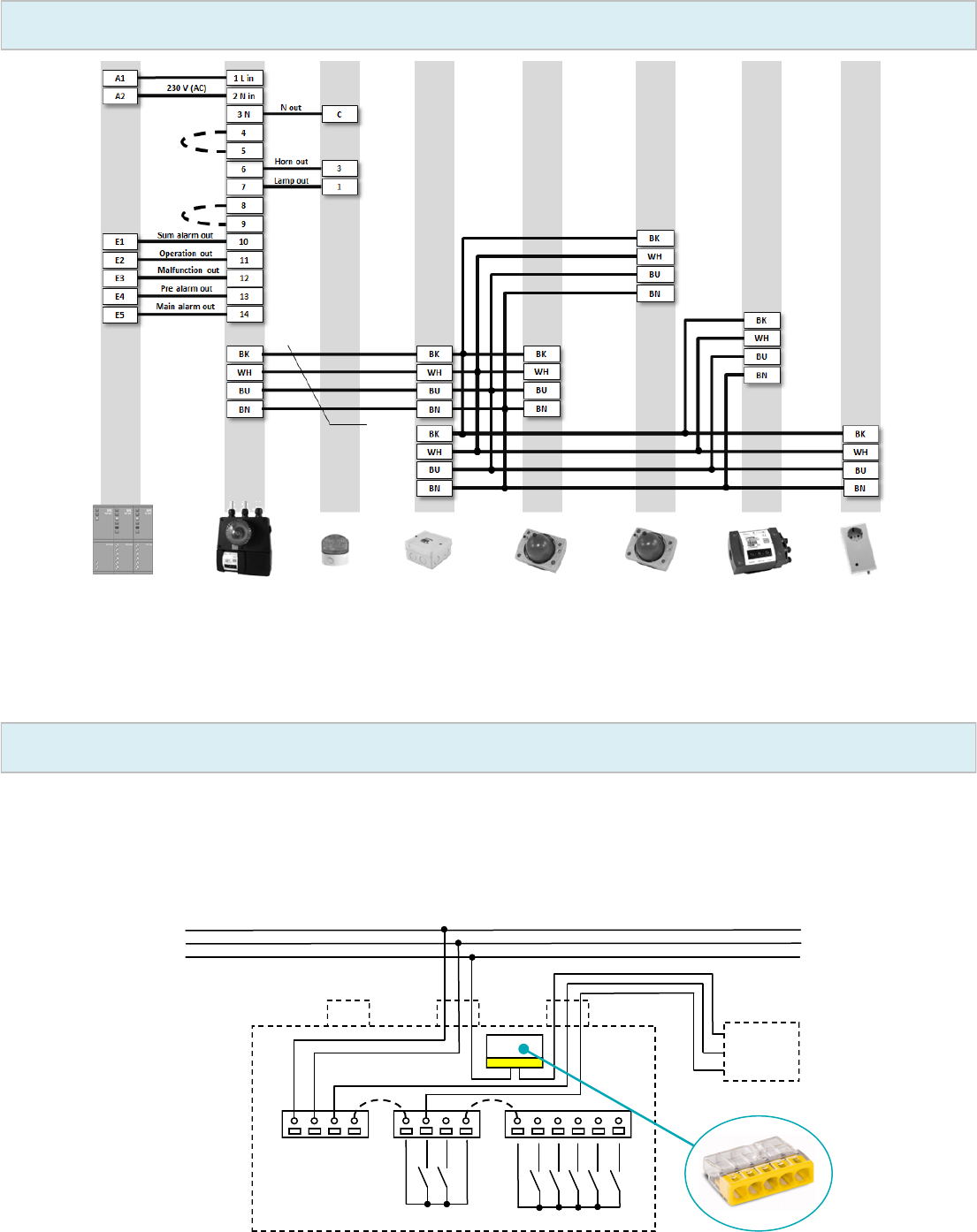
11: Operaon out"Operaon" status display (control output)
12: Malfuncon out "Malfuncon" status display (control output)
13: Pre-alarm out"Pre-alarm" status display(control output)
14: Main alarm out"Main alarm" status display(control output)
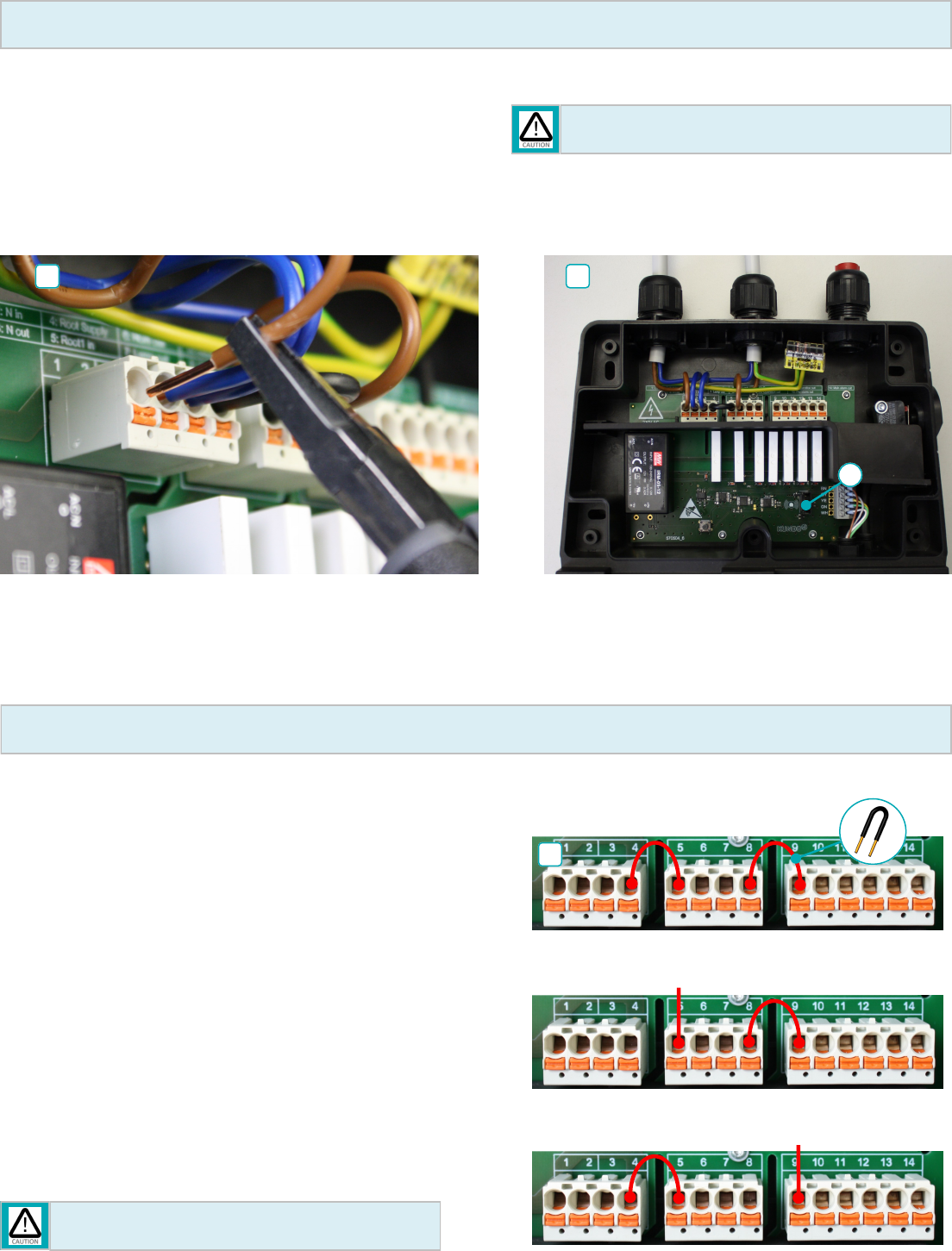
Connecon examples:
230 V internally (not oang):
block 2 and 3: ext. power supply (oang):
block 2: 230 V internally (not oang) / block 3: ext. control voltage
(oang):
14
ext. control voltage (e.g. 24 V DC or 230 V AC)
ext. control voltage
block 1block 2block 3
For connecons 6, 7, and 10 - 14, note that there is a maximum
permissible current load of 2 A respecvely.
Assembly instrucons CO2 CONTROL AM / AM PLUS
-6-
Assembly 7
14. Once the AM / AM PLUS unit is completely wired, the unit should
be closed up again. To do this, ghten the mounng screws ④ on the
housing. When closing up the device, note that for AM PLUS units,
you will rst of all need to reconnect the alarm light to the circuit
board, in socket ⑩ (see Image 13 on Page 5).
When screwing on the cover, make sure that
this is ght, so as to ensure the connued seal
of the device. KUNDOxT accepts no liability
for damage due to incorrect installaon!
15. Seng the geographic height
On the le side of the warning unit, there is
a rotary switch for seng the locaon
height at which the detecon system is
installed.
Check the current height against the height
range given in the table and set the posion
(0...9) of the switch so that the number on
the switch is above the marking on the
housing (for more details, see Item 16 on
Page 6).
Level
Height [m]
above sea level
00 .. 250
1250 .. 500
2500 .. 750
3750 .. 1000
41000 .. 1250
51250 .. 1500
61500 .. 1750
71750 .. 2000
82000 .. 2250
92250 .. 2500
16
15
Assembly 8
Aer seng the height, the housing on the rotary switch must be sealed
with the aached transparent adhesive lm.
17. Sensor unit
The sensor unit must now be connected. To do this,
connect the connector cable to the distributor. You can
nd further details in the CO2 CONTROL gas warning
system operang instrucons.
17
18
8
16.
Assembly instrucons CO2 CONTROL AM / AM PLUS
-7-
CO2 CONTROL installaon plan 1
Switching unitSignal unit
Sensor unit 2Sensor unit 12 distributorsAlarm unit
Superordinate
control system
Control line
CO2 CONTROL
CO2 CONTROL
PA AM /
PA AM PLUS
*
*
* See page 5 (Assembly 6) for connecon examples
DIN VDE 0100-410 412.2.3.2:
For a circuit which supplies equipment belonging to protecon class II, a conducve protecve conductor must be used throughout the enre cabling system and con-
nected to a terminal in each installaon device, ...
L
L
N
PE
L
N
PE
LNN
N
PE
Signal
*
*
* See page 5 (Assembly 6) for connecon examples
CO2 CONTROL installaon plan 2
Assembly instrucons CO2 CONTROL AM / AM PLUS
-8-
System check
Annual check of safety device funconality is required in accordance with DIN EN 378!
When used in freezer units, the sensor units must be adjusted to the ambient temperature before commissioning. Otherwise, undened fault messages
will be shown, which will disappear once the sensor units are acclimased. Only then will your system be ready to run!
19. Once inialisaon is complete, the system's funcon can be checked by means of CO
2
contact tesng. The CO
2
concentraon should be between 3% and 100 % in
order to trigger an alarm. The blue protecve cover on the sensor unit is ed with a nozzle, through which gas can be fed into the sensor unit. If the gas has a CO
2
concentraon of 1.5%, it will trigger the pre-alarm; at 3% CO
2
, it will trigger the main alarm.
Test the fault message by disconnecng the plug on a sensor unit.
Recurring checks of CO
2
refrigeraon equipment:
Regular annual checks of the safety device in accordance with DIN EN 378, during which alarm triggering with CO
2
is not only used to check the CO
2
CONTROL but also
in parcular the transmission and subsequent acons by the control system and/or building management system. No checks of the alarm thresholds and their
tolerance ranges with a test gas are required! Calibraon is performed at our plant aer 4 years of operaon, by swapping out the sensor on site. For further
informaon, please refer to the CO
2
CONTROL installaon and operang instrucons.
Imprint
Copyright to this documentaon has been asserted by KUNDOxT GmbH. This documentaon may not be altered, expanded, reproduced or disclosed to third pares
without the prior wrien approval of KUNDOxT GmbH. Design and equipment subject to change.
Commissioning
18. When the external power supply from the superordinate control system is switched on, the system immediately switches to ALARM mode for safety reasons, and
thereby signals that no CO
2
system inialisaon has yet been performed.
Press and hold the seng key ③ on the AM / AM PLUS unit. The alarm will switch o immediately! Hold the key ③ and then press the “Alarm o” key ⑥ on the
PA warning unit. Keep key ⑥ pressed, and release key ③. Hold key ⑥ down unl the buzzer sounds. Then, release the buon. Upon a successful start of inialisa-
on, you will hear a short beep and cking from the warning unit.
The system will then inialise by itself. The process ends with 4 short signal sounds and the green power lights on the system components will light. Aer this, each
device must be checked to ensure that all of their green power lights are lit. If this is not the case, the procedure described above must be repeated. Also check the
status display of the superordinate control system.
If inialisaon is not successful, the system will switch to main alarm mode, the red light will light and the sound cannot be switched o. The inialisaon must be
Gebruikershandleiding.com neemt misbruik van zijn services uitermate serieus. U kunt hieronder aangeven waarom deze vraag ongepast is. Wij controleren de vraag en zonodig wordt deze verwijderd.
Product:
Spelregels forum
Om tot zinvolle vragen te komen hanteren wij de volgende spelregels:
lees eerst de handleiding door;
controleer of uw vraag al eerder door iemand anders is gesteld;
probeer uw vraag zo duidelijk mogelijk te stellen;
heeft u een probleem en al geprobeerd om dit op te lossen, vermeld dit erbij aub;
heeft u een oplossing gekregen van een bezoeker dan horen wij dat graag in dit forum;
wilt u een reactie geven op een vraag of antwoord, gebruik dan niet dit formulier maar klik op de knop 'reageer op deze vraag';
uw vraag wordt direct op de website gezet; vermijd daarom persoonlijke gegevens in te vullen;
Belangrijk! Als er een antwoord wordt gegeven op uw vraag, dan is het voor de gever van het antwoord nuttig om te weten als u er wel (of niet) mee geholpen bent! Wij vragen u dus ook te reageren op een antwoord.
Belangrijk! Antwoorden worden ook per e-mail naar abonnees gestuurd. Laat uw emailadres achter op deze site, zodat u op de hoogte blijft. U krijgt dan ook andere vragen en antwoorden te zien.
Abonneren
Abonneer u voor het ontvangen van emails voor uw Kundo xT CO2 Control AM Plus 2018 bij:
nieuwe vragen en antwoorden
nieuwe handleidingen
U ontvangt een email met instructies om u voor één of beide opties in te schrijven.
Ontvang uw handleiding per email
Vul uw emailadres in en ontvang de handleiding van Kundo xT CO2 Control AM Plus 2018 in de taal/talen: Engels als bijlage per email.
De handleiding is 6,38 mb groot.
U ontvangt de handleiding per email binnen enkele minuten. Als u geen email heeft ontvangen, dan heeft u waarschijnlijk een verkeerd emailadres ingevuld of is uw mailbox te vol. Daarnaast kan het zijn dat uw internetprovider een maximum heeft aan de grootte per email. Omdat hier een handleiding wordt meegestuurd, kan het voorkomen dat de email groter is dan toegestaan bij uw provider.
Stel vragen via chat aan uw handleiding
Stel uw vraag over deze PDF
Andere handleiding(en) van Kundo xT CO2 Control AM Plus 2018
Uw handleiding is per email verstuurd. Controleer uw email
Als u niet binnen een kwartier uw email met handleiding ontvangen heeft, kan het zijn dat u een verkeerd emailadres heeft ingevuld of dat uw emailprovider een maximum grootte per email heeft ingesteld die kleiner is dan de grootte van de handleiding.
Er is een email naar u verstuurd om uw inschrijving definitief te maken.
Controleer uw email en volg de aanwijzingen op om uw inschrijving definitief te maken
U heeft geen emailadres opgegeven
Als u de handleiding per email wilt ontvangen, vul dan een geldig emailadres in.
Uw vraag is op deze pagina toegevoegd
Wilt u een email ontvangen bij een antwoord en/of nieuwe vragen? Vul dan hier uw emailadres in.