1-5
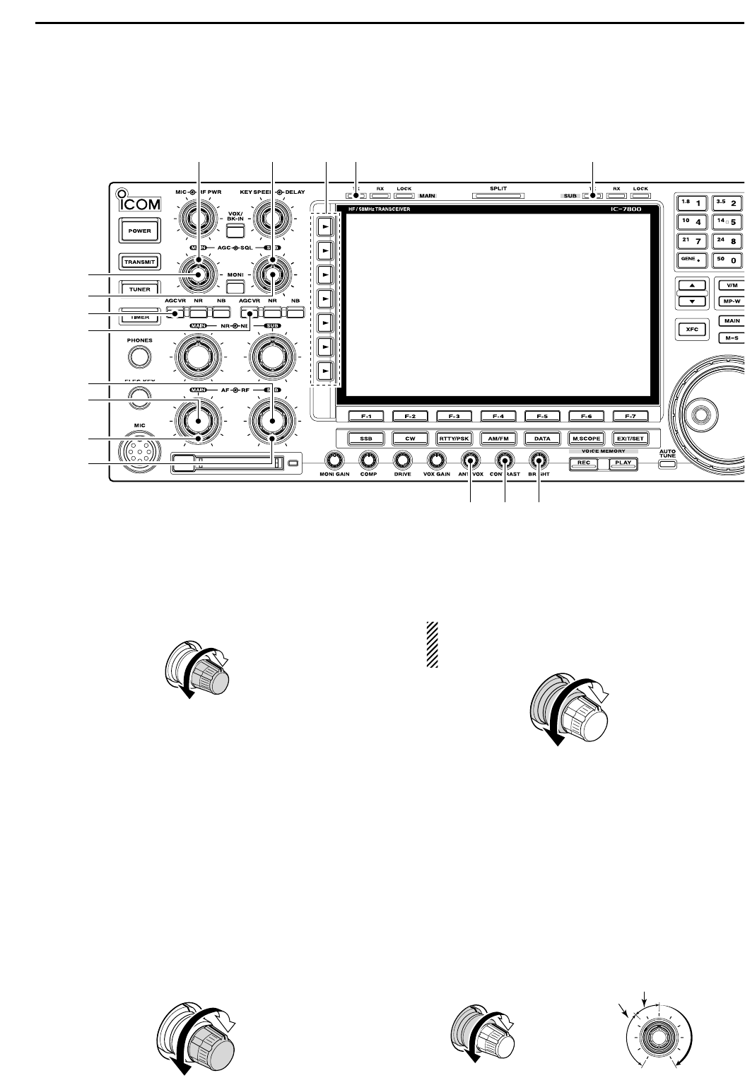
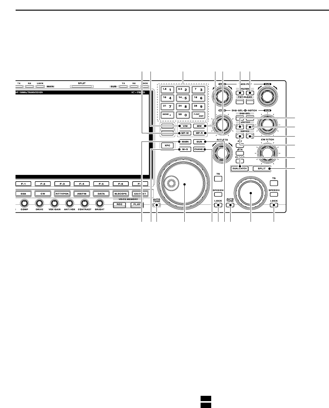
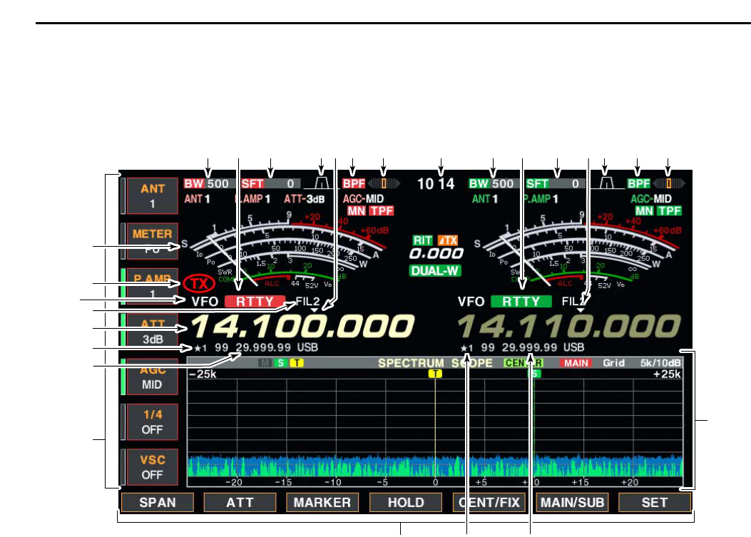
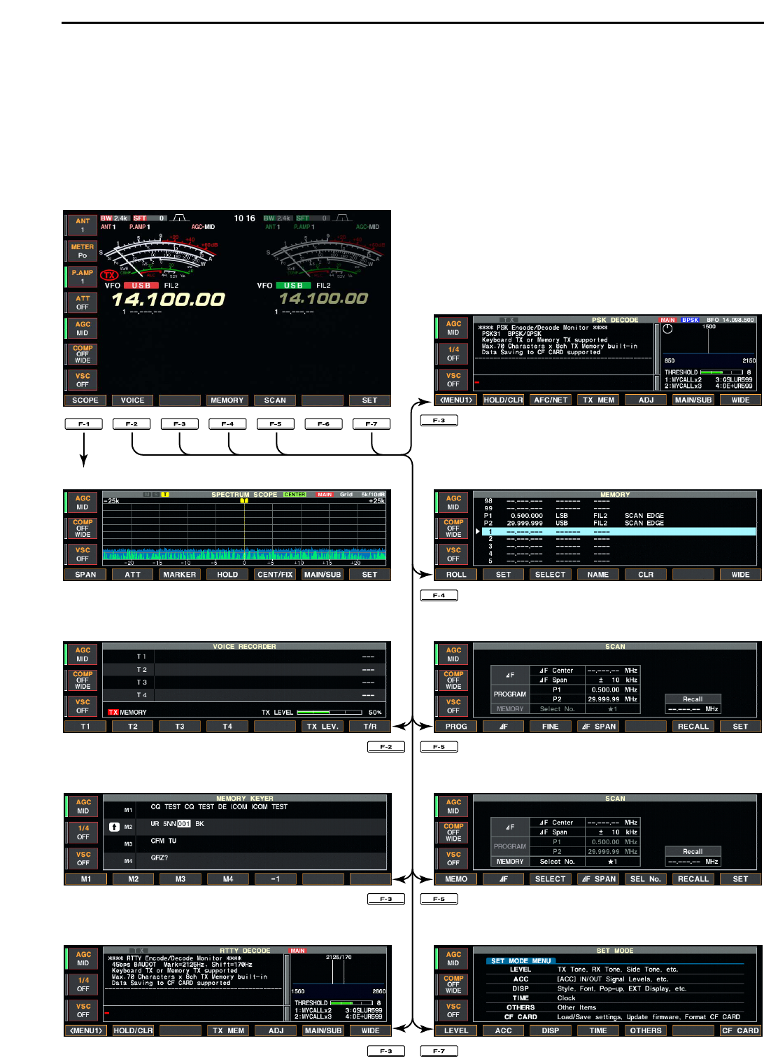
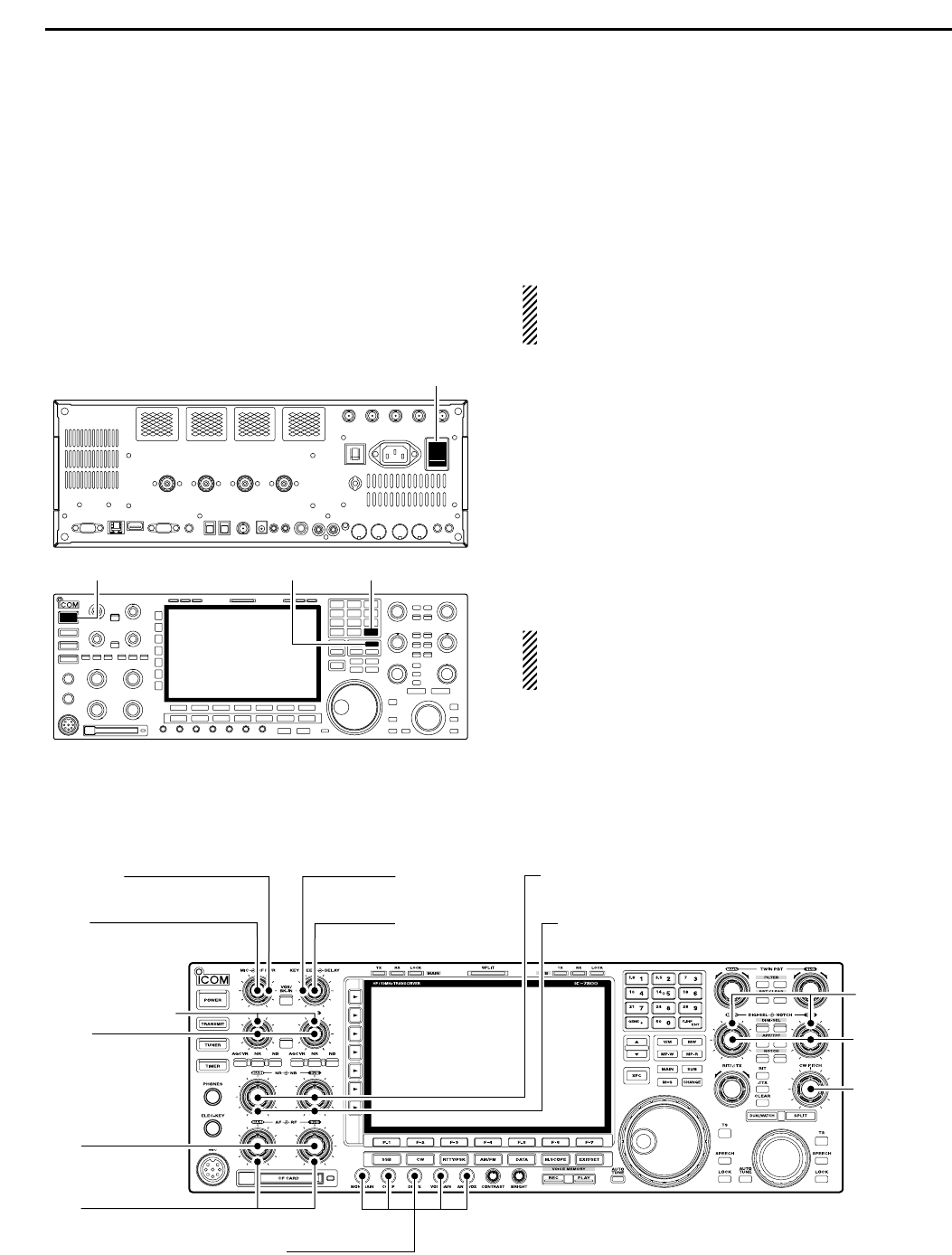
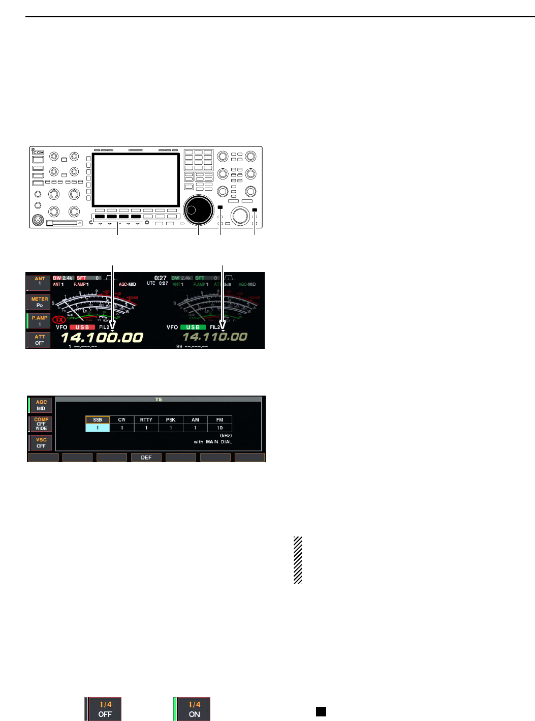
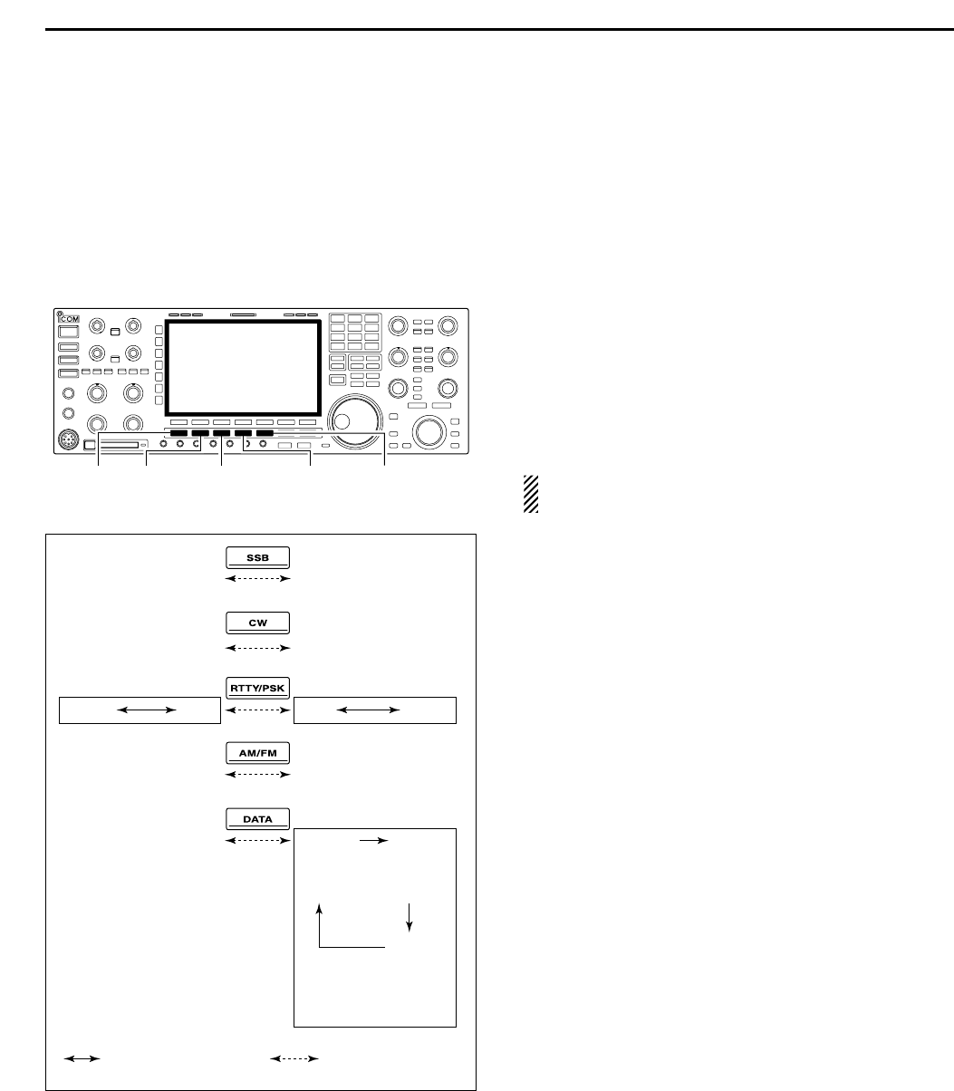
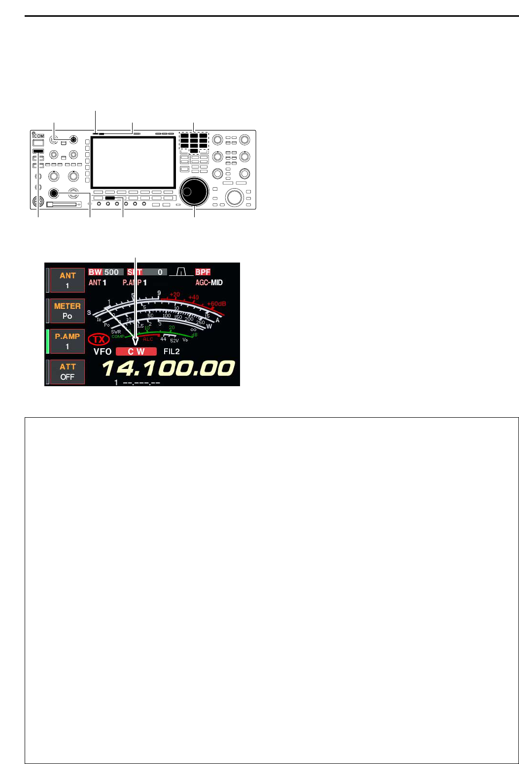
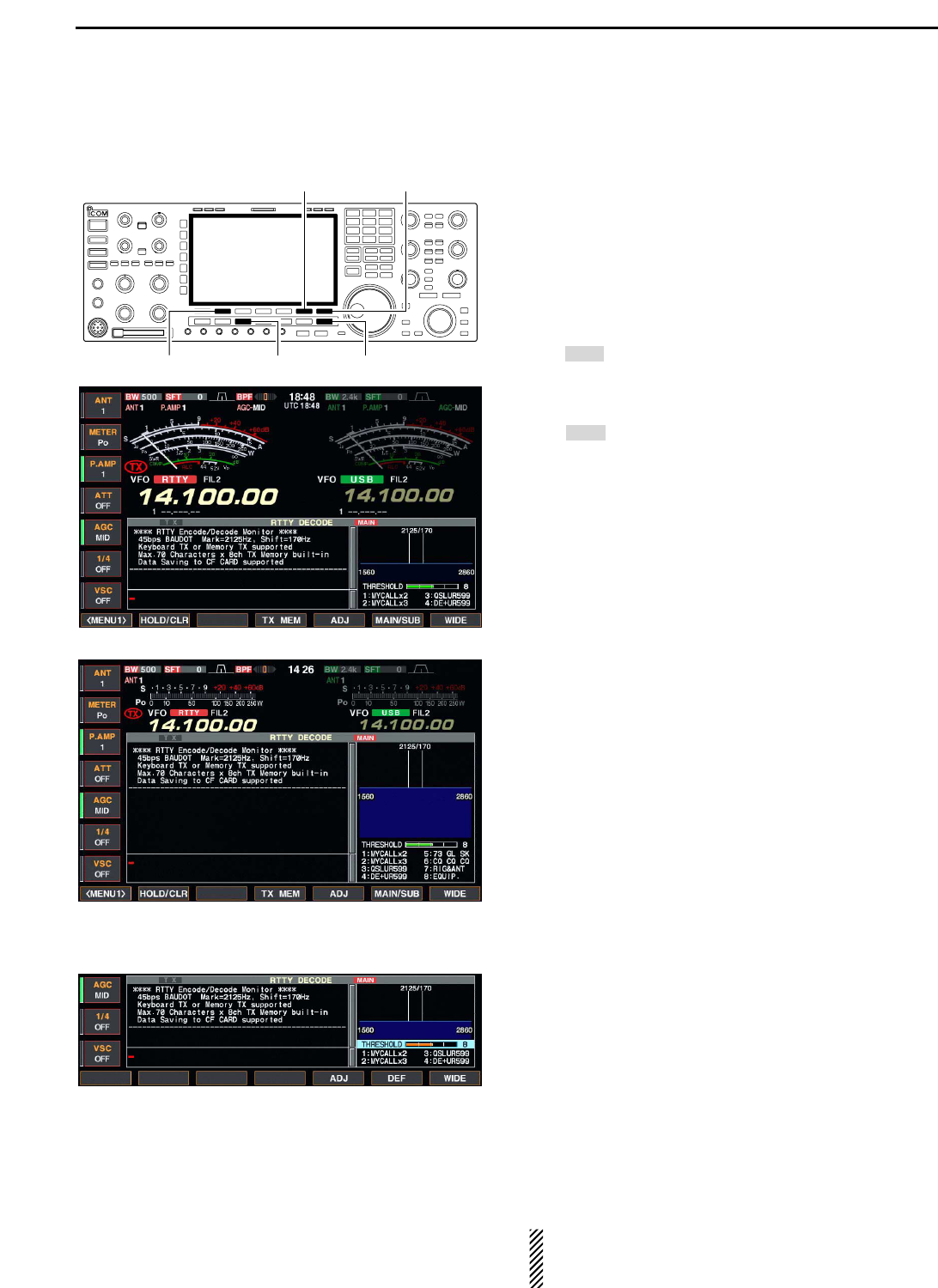
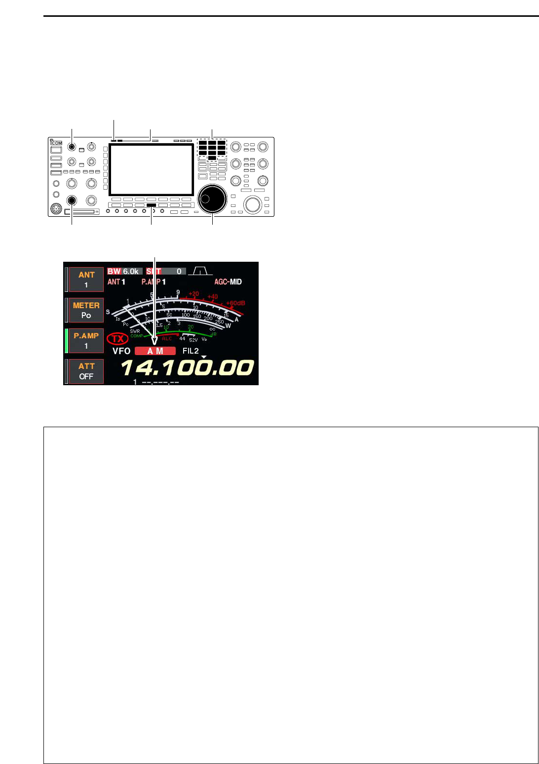
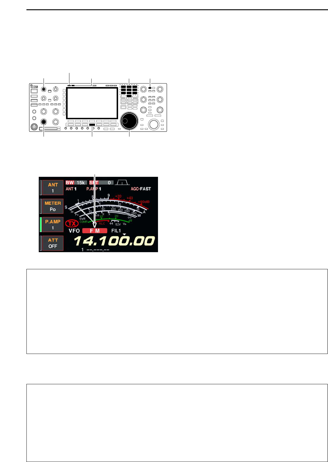
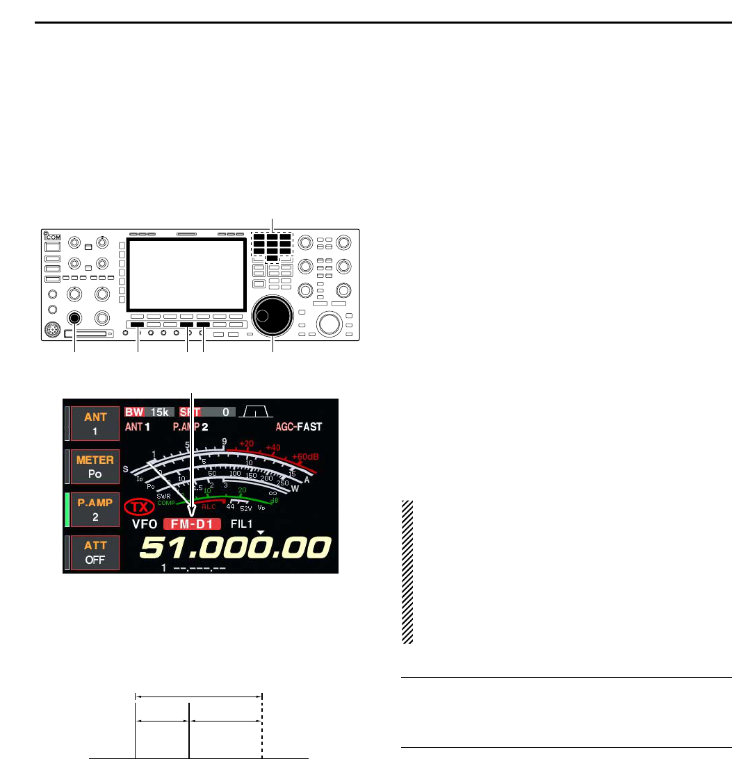
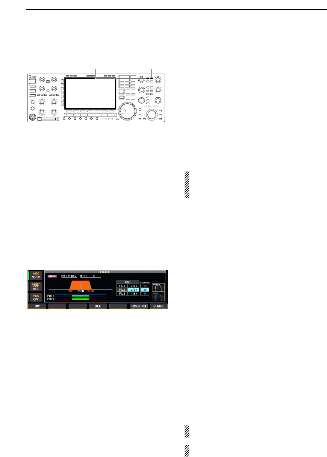
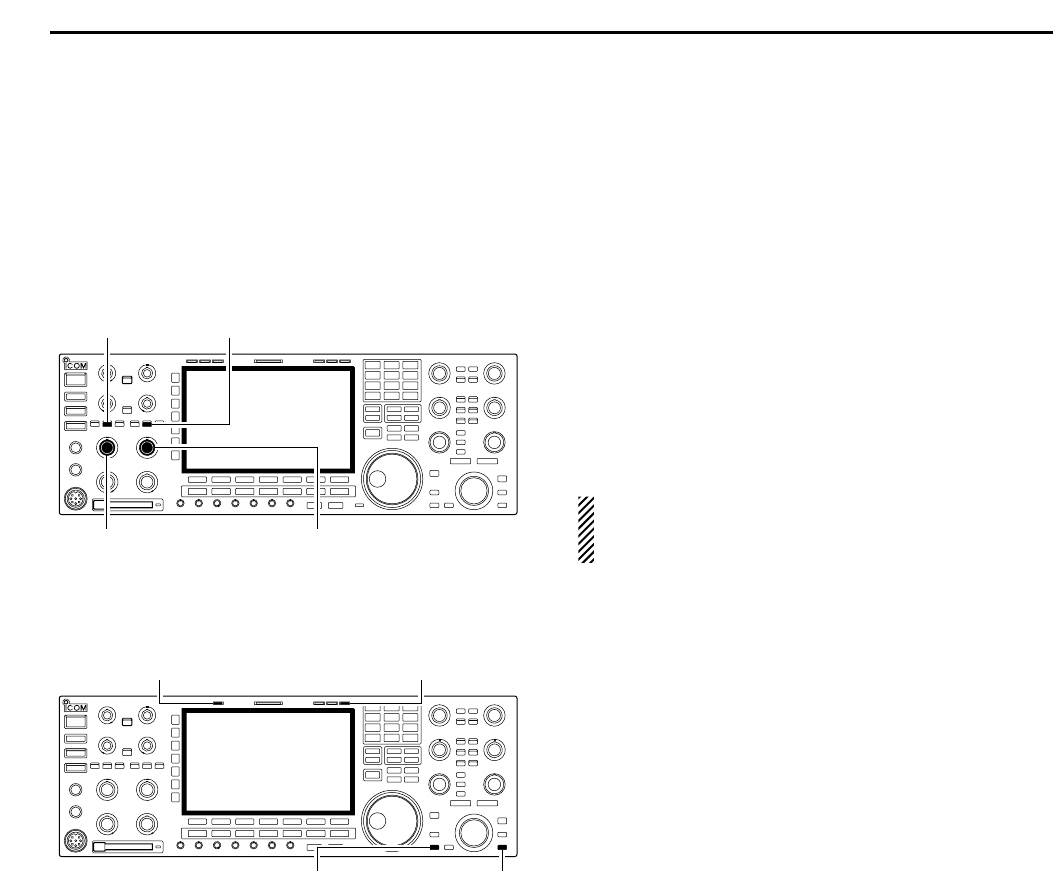
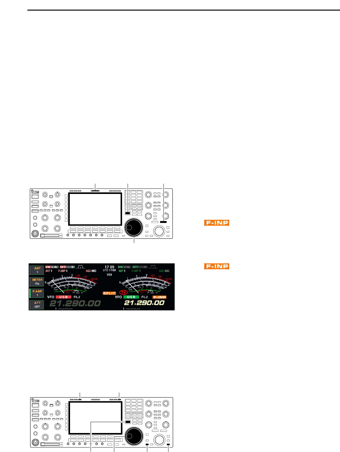
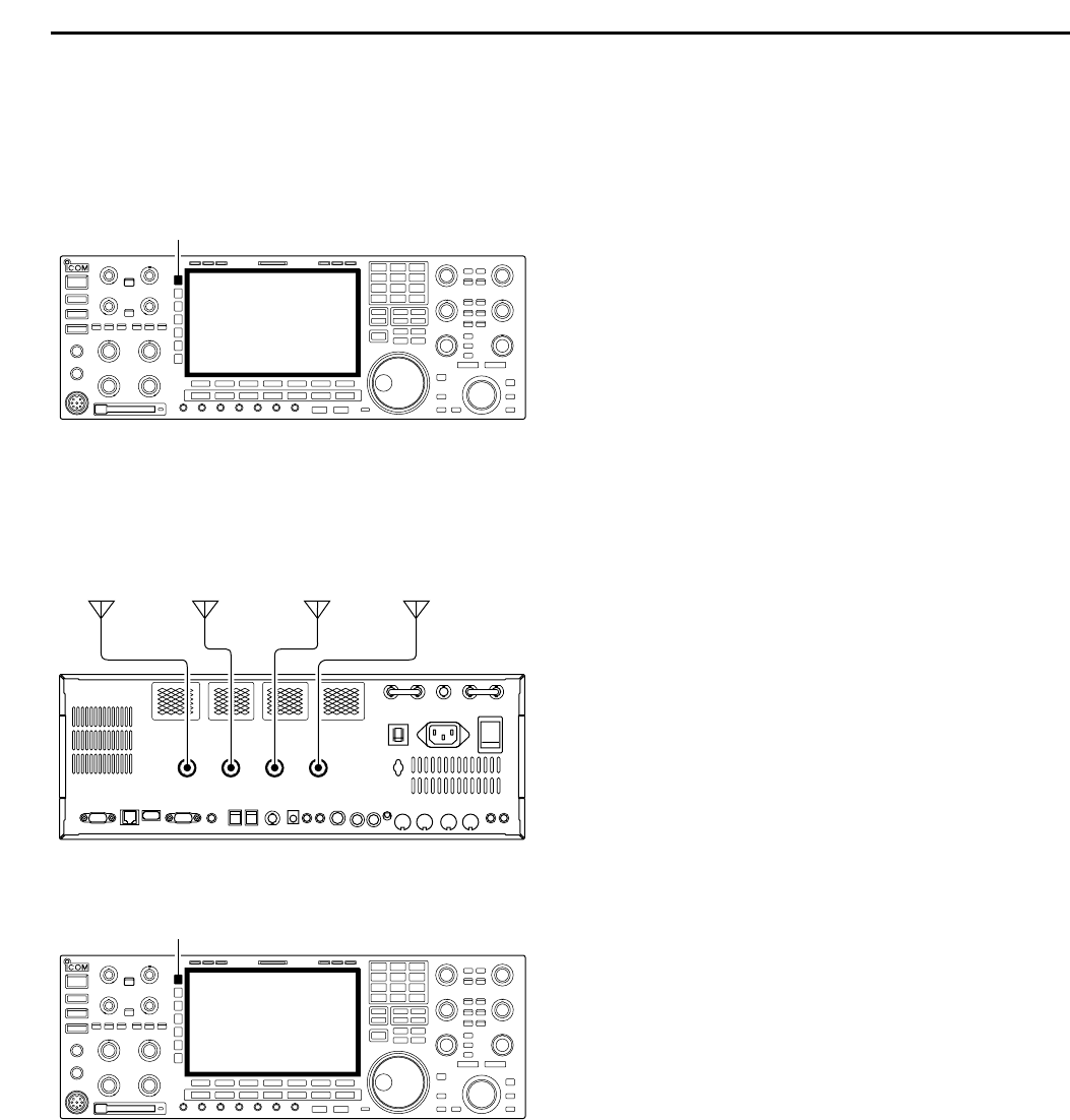
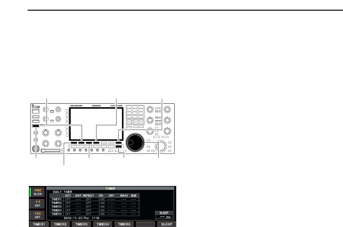
@9 MULTI-FUNCTION SWITCHES
Push to select the functions indicated in the LCD
display to the right of these switches.
• Functions vary depending on the operating condition.
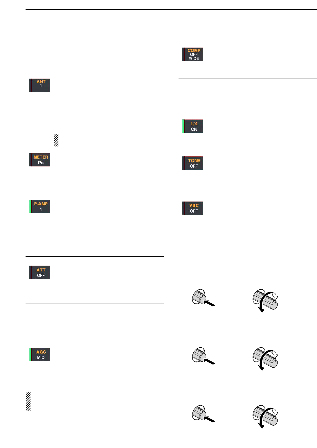
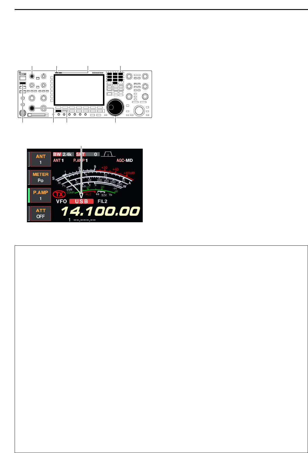
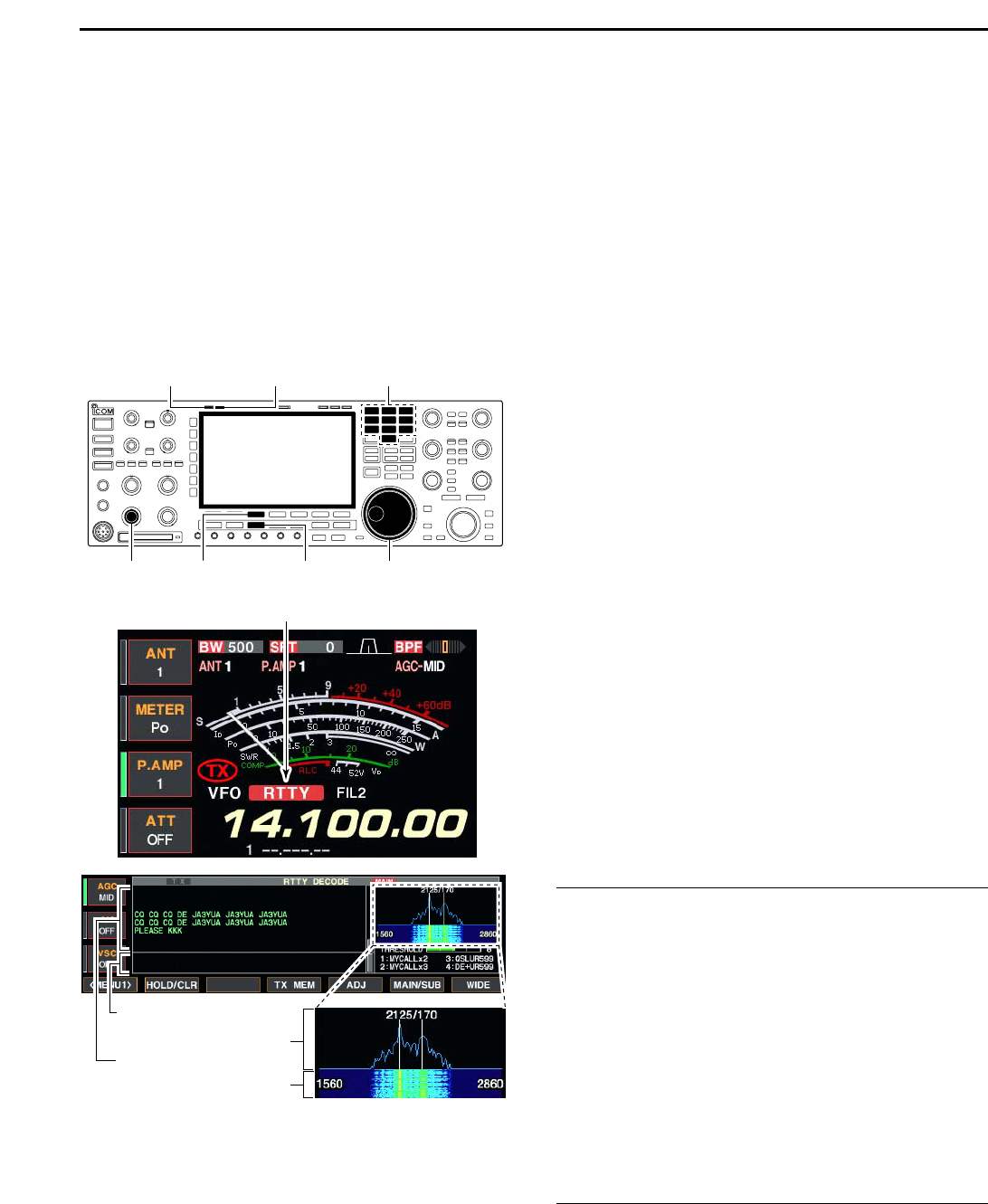
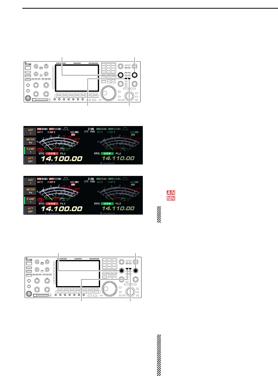
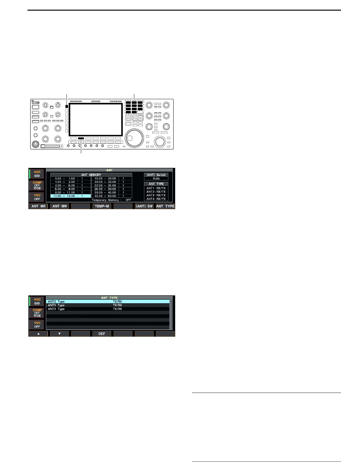
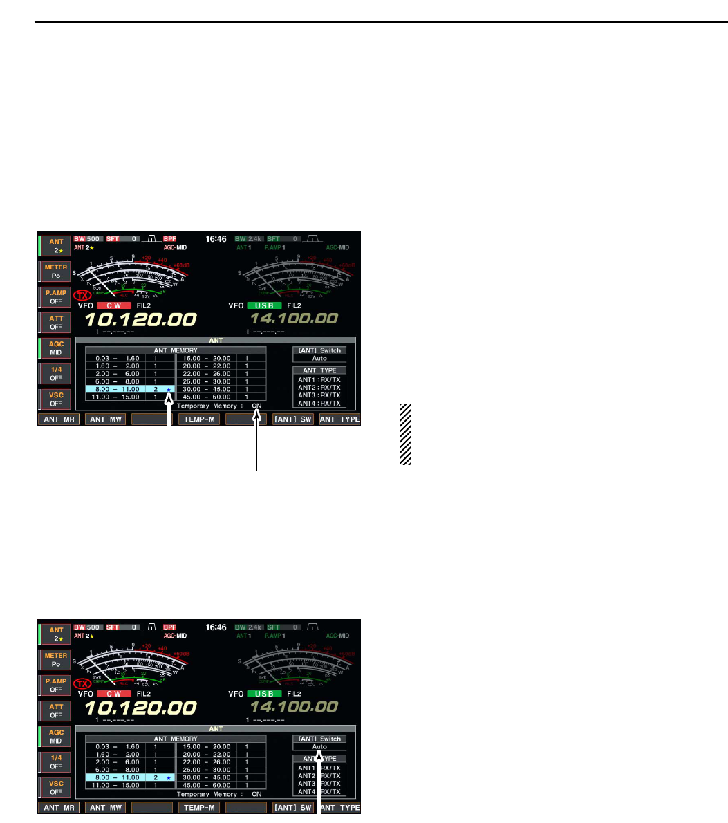
➥ Selects the antenna connector from
ANT1, ANT2, ANT3 and ANT4 when
pushed. (p. 10-2)
➥ Displays antenna selection memory
when pushed for 1 sec.
• When the receive antenna is activated, the
antenna which is connected to [ANT4] is
used for receive only.
When a transverter is in use, this [ANT]
does not function and ‘TRV’ appears.
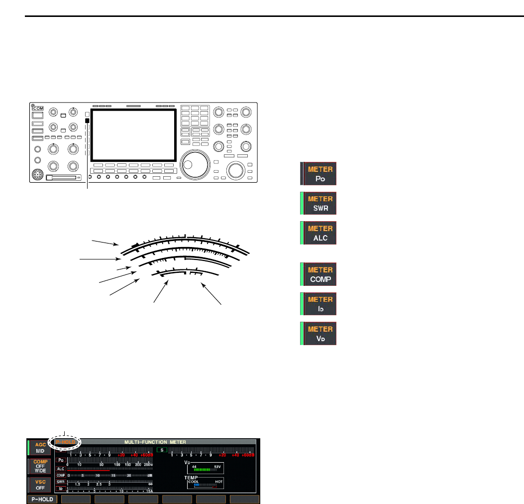
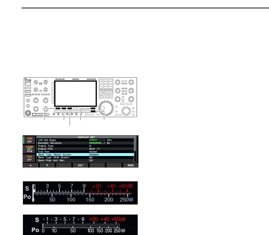
➥ Selects RF power (Po), SWR, ALC,
COMP, VD or ID metering during transmit.
(p. 3-10)
➥ Switches the multi-function digital meter
ON and OFF when pushed for 1 sec.
(p. 3-10)
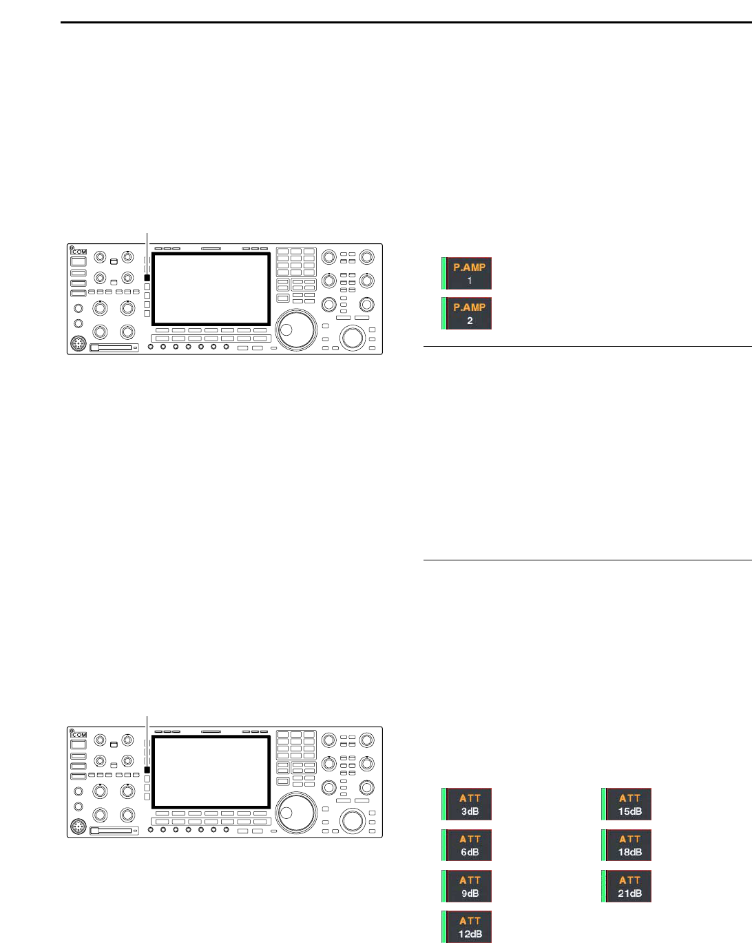
➥ Selects one of 2 receive RF preamps or
bypasses them. (p. 5-9)
• “P. AMP1” activates 10 dB preamp.
•
“P. AMP2” activates 16 dB high-gain preamp.
✔
What is the preamp?
The preamp amplifies received signals in the front end cir-
cuit to improve S/N ratio and sensitivity. Select “P. AMP1” or
“P. AMP2” when receiving weak signals.
➥ Selects 6 dB, 12 dB or 18 dB attenuator
when pushed. (p. 5-9)
➥ Selects 3 dB, 6 dB, 9 dB, 12 dB, 18 dB,
or 21 dB attenuator when pushed for
1 sec. (p. 5-9)
✔
What is the attenuator?
The attenuator prevents a desired signal from distorting
when very strong signals are near the desired frequency, or
when very strong electric fields, such as from a broadcast-
ing station, are near your location.
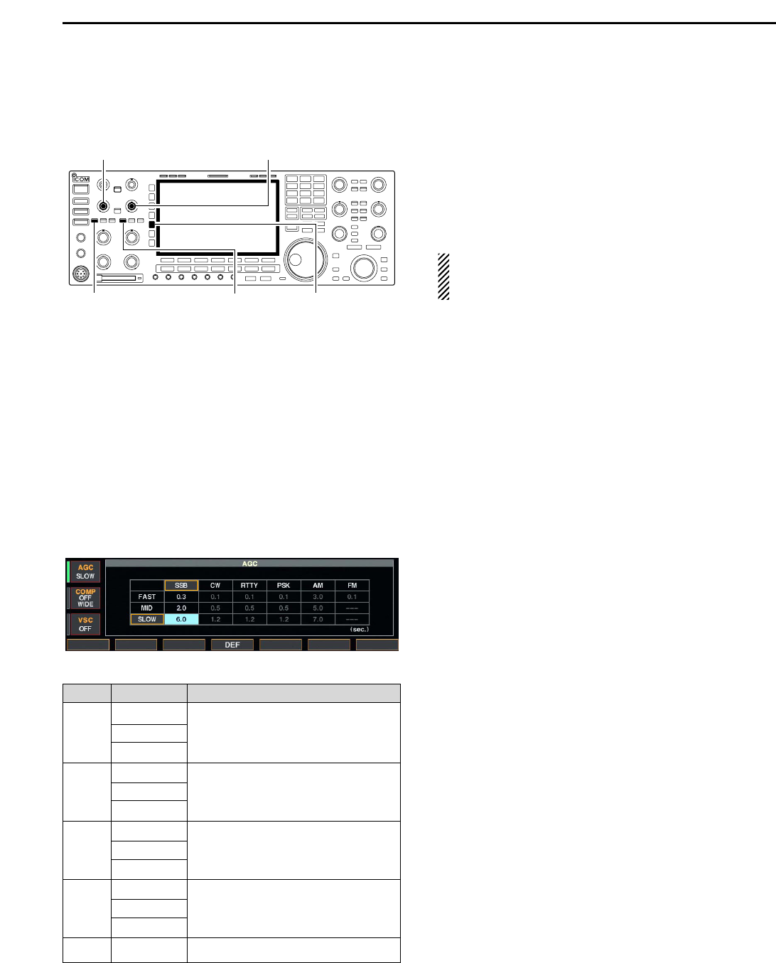
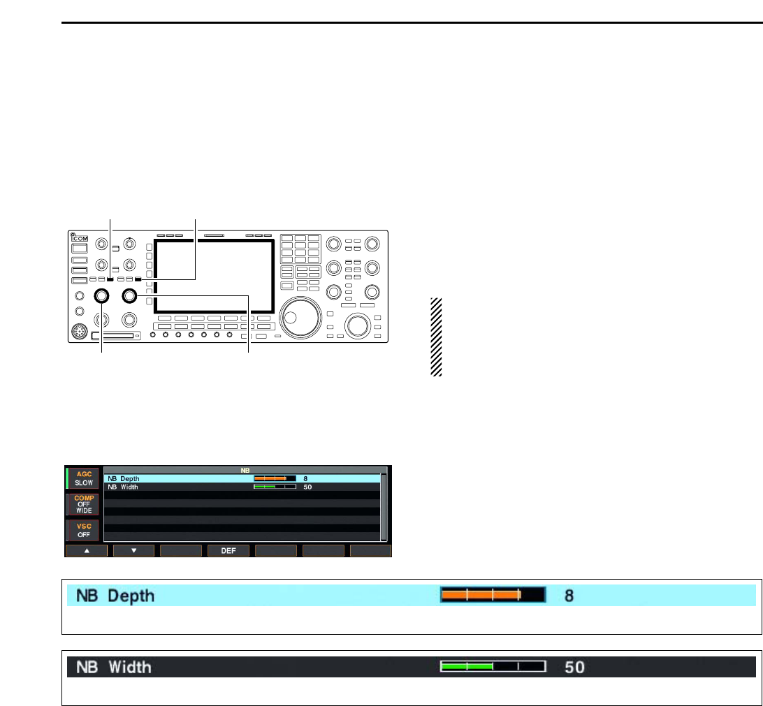
➥ Activates and selects fast, middle or slow
AGC time constant when pushed. (p. 5-
11)
• In FM mode, only “FAST” is available.
➥ Enters the AGC set mode when pushed
for 1 sec. (p. 5-11)
AGC time constant can be set between 0.1 to
8.0 sec.
(depends on mode), or turned OFF. When
AGC is “OFF,” the S-meter does not function.
✔
What is the AGC?
The AGC controls receiver gain to produce a constant audio
output level, even when the received signal strength varies
dramatically. Select “FAST” for tuning and then select “MID”
or “SLOW” depending on the receiving condition.
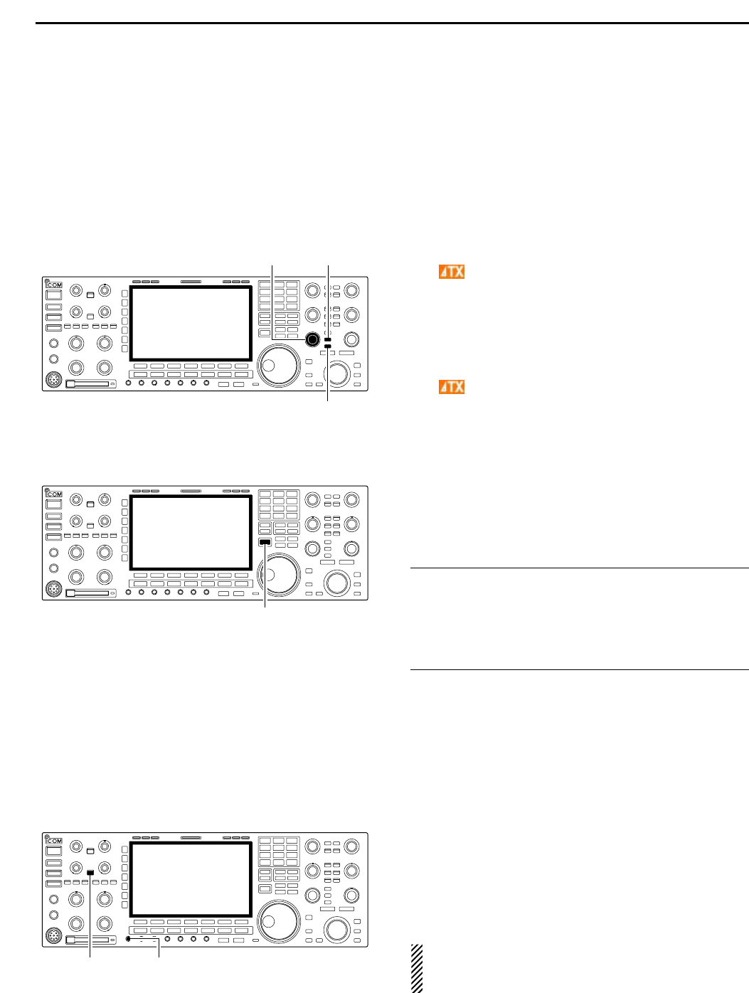
➥ Turns the speech compressor ON and
OFF in SSB mode. (p. 6-5)
➥ Switches the narrow, middle or wide
compression when pushed for 1 sec.
✔
What is the speech compressor?
The speech compressor compresses the transmitter audio
input to increase the average audio output level, to increase
talk power. This function is effective for long-distance com-
munication or when propagation conditions are poor.
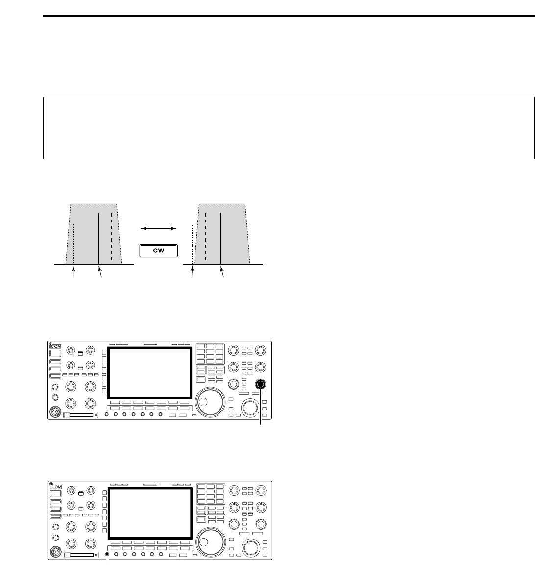
➥ Turns the
1
⁄4
-speed tuning function ON
and OFF in SSB data, CW, RTTY and
PSK modes. (p. 3-6)
•
1
⁄4 function sets dial rotation to
1
⁄4 of normal
speed for fine tuning.
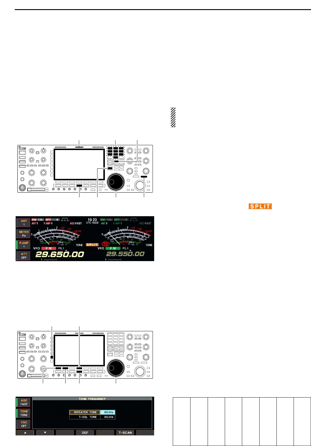
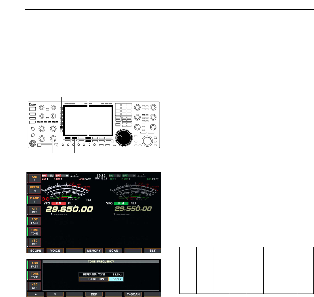
➥ Switches between the tone encoder,
tone squelch function and no-tone oper-
ation when pushed in FM mode. (pgs. 4-
32, 4-33)
➥ Enters the tone set mode when pushed
for 1 sec. in FM mode. (pgs. 4-32, 4-33)
➥ Switches the voice squelch control func-
tion ON and OFF; useful for scanning.
(p. 9-3)
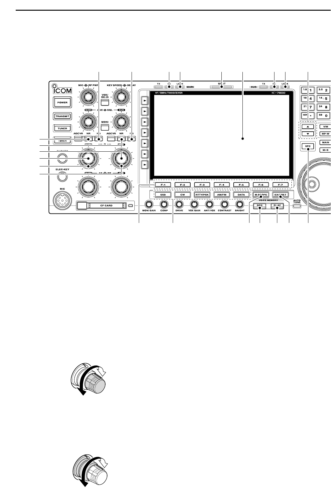
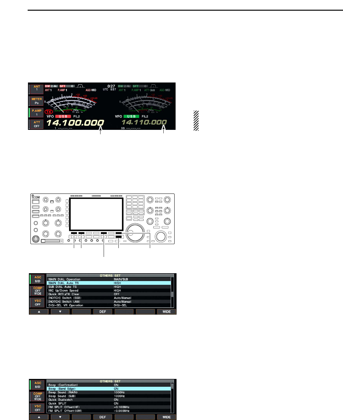
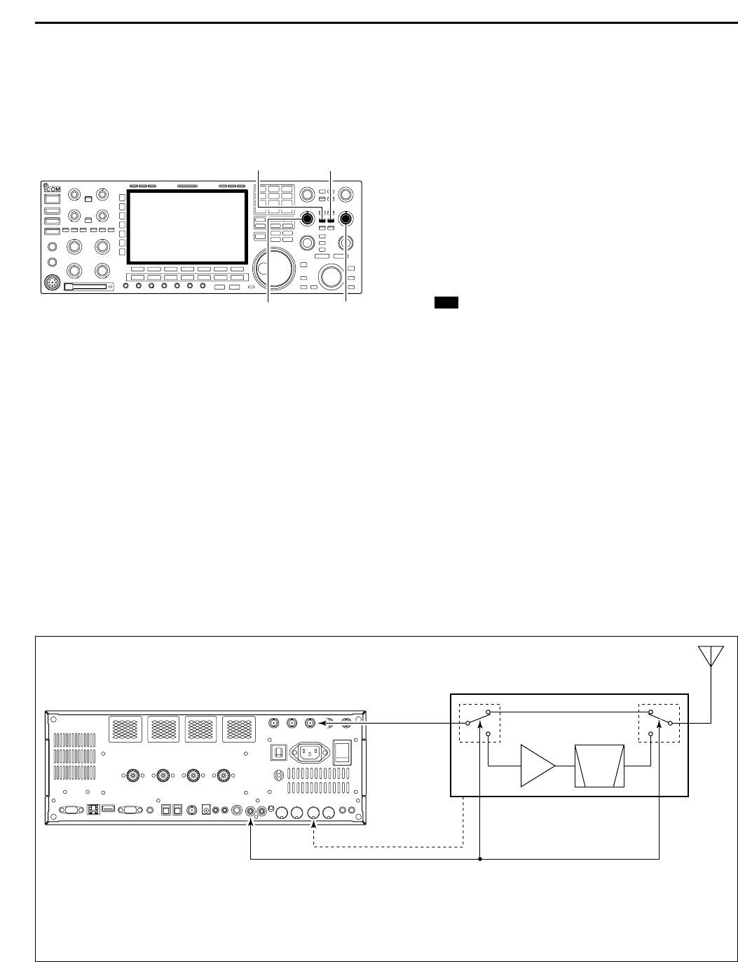
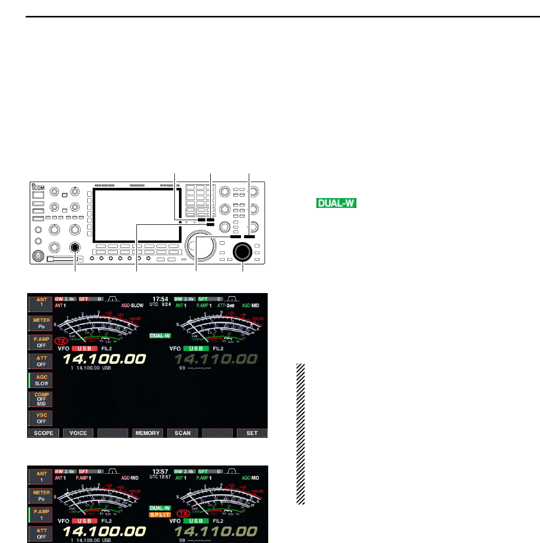
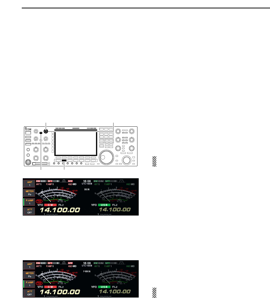
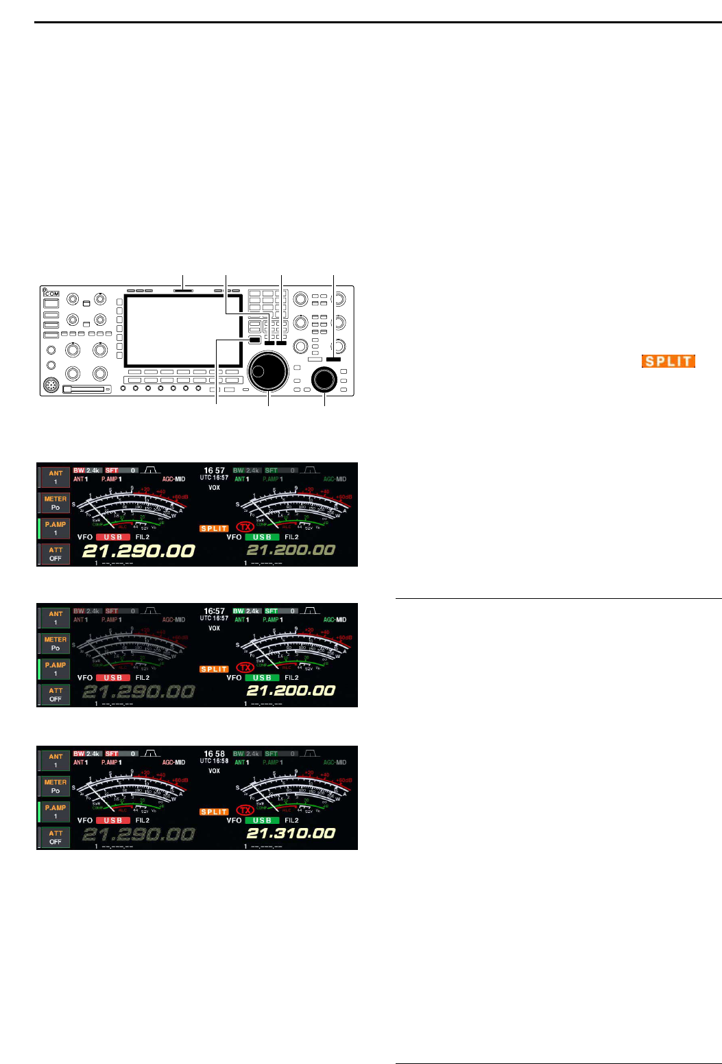
#0 TRANSMIT INDICATOR [TX] (for MAIN band)
#1 TRANSMIT INDICATOR [TX] (for SUB band)
Lights red while transmitting.
• SUB band’s [TX] indicator lights only when in split oper-
ation.
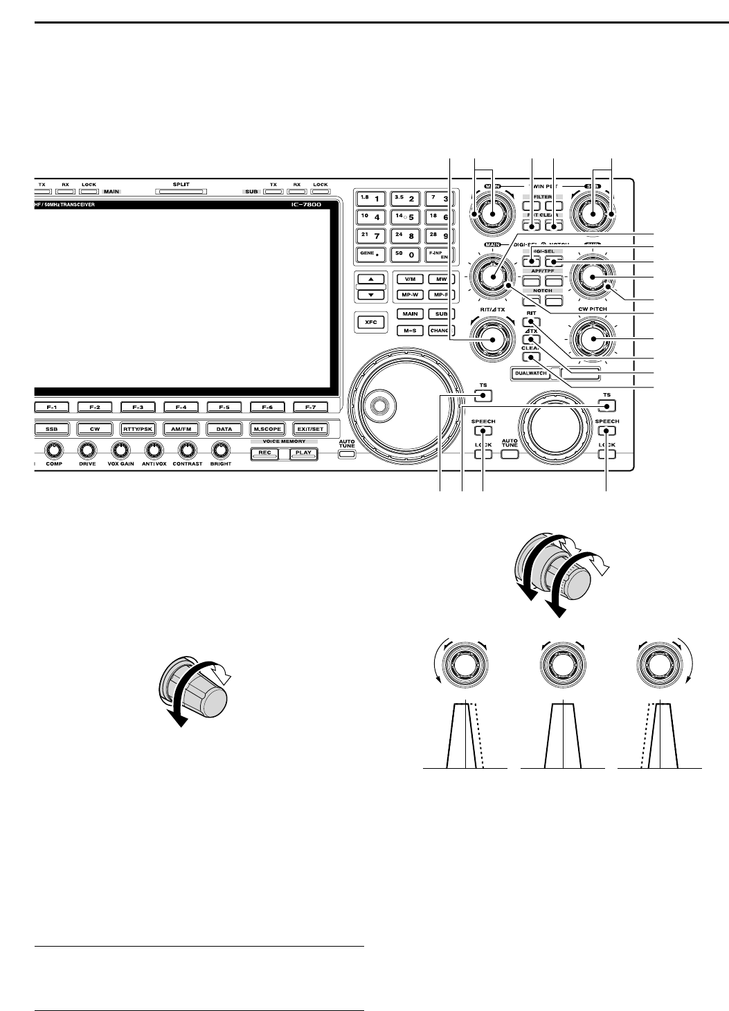
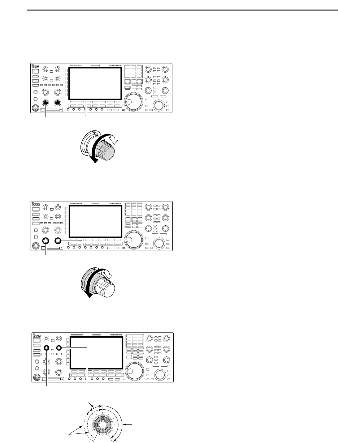
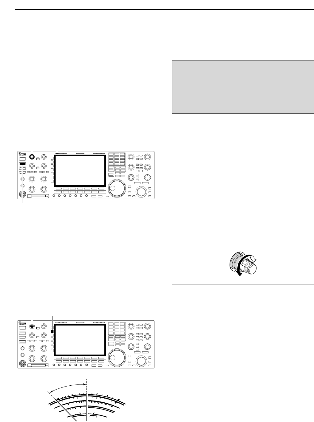
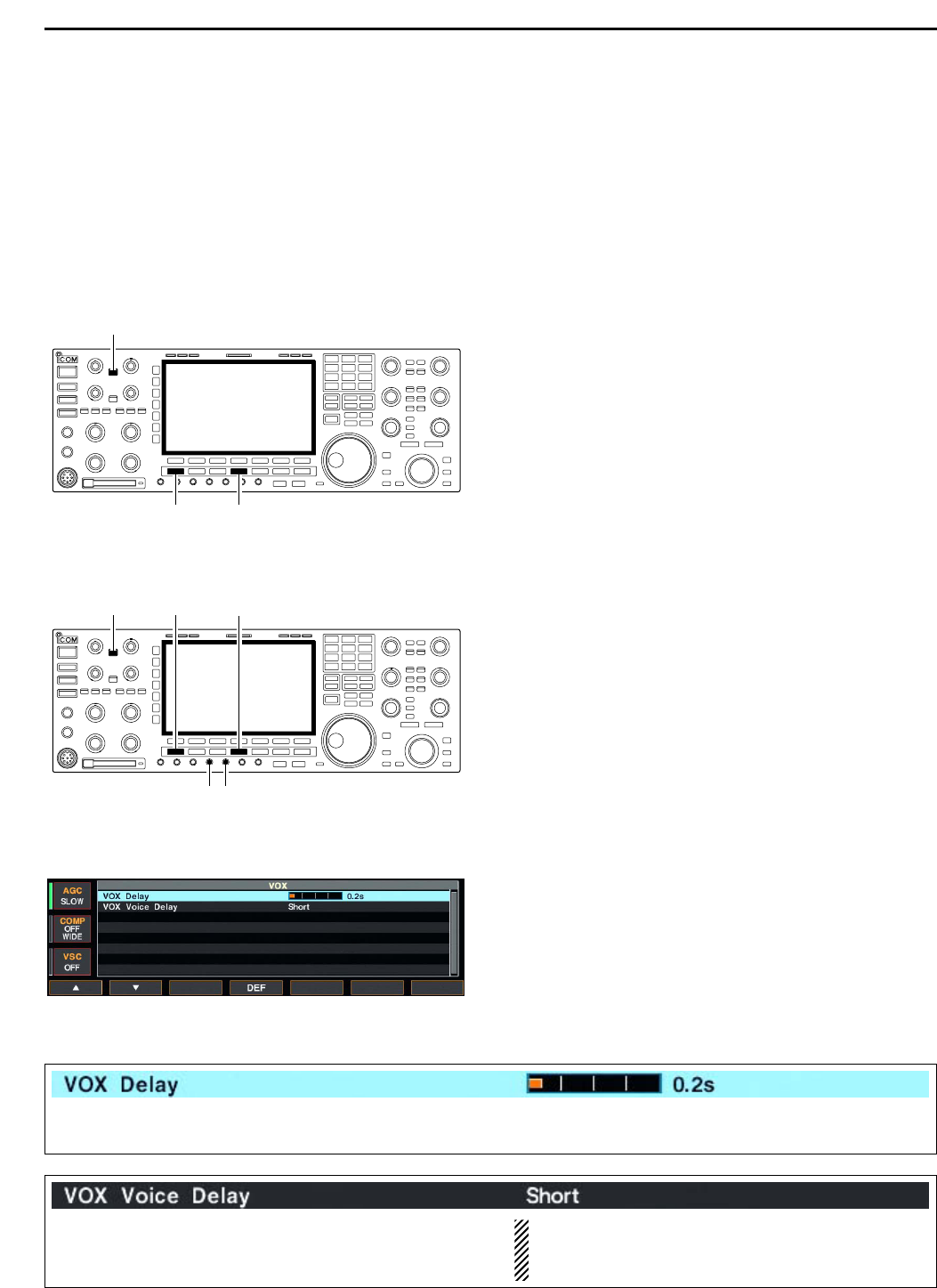
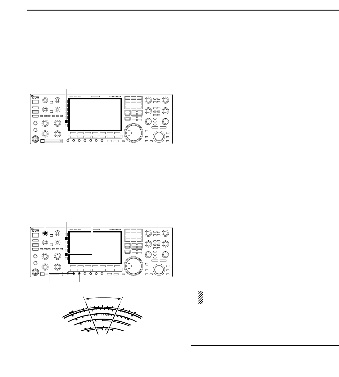
#2 ANTI VOX CONTROL [ANTI VOX] (p. 6-2)
Adjusts the VOX deactivate level to prevent un-
wanted VOX activation from the speaker audio.
#3 LCD CONTRAST CONTROL [CONTRAST]
Adjusts the LCD contrast.
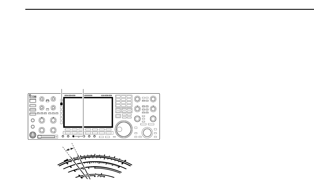
#4 LCD BRIGHTNESS CONTROL [BRIGHT]
Adjusts the LCD brightness.