2
1
PANEL DESCRIPTION
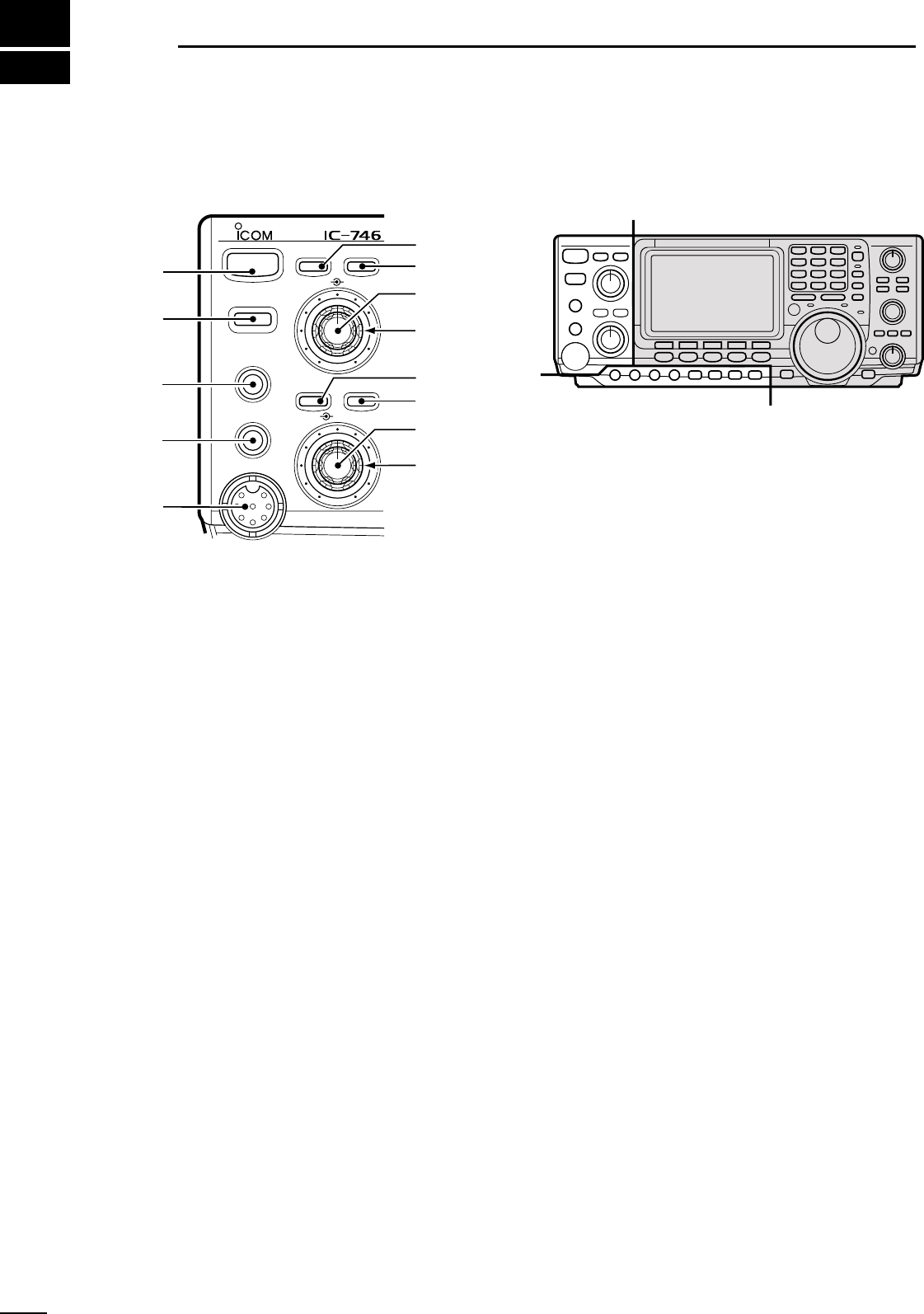
1-1 Front panel
q POWER SWITCH [POWER]
➥ Push momentarily to turn power ON. (p. 11)
• Turn the optional DC power supply ON in advance.
➥ Push and hold to turn power OFF.
w TRANSMIT SWITCH [TRANSMIT]
Toggles between transmit and receive.
• The [TX] indicator lights red while transmitting and the
[RX] indicator lights green when the squelch is open.
e HEADPHONE JACK [PHONES] (p. 67)
Accepts headphones.
• When headphones are connected, the internal speaker
or connected external speaker does not function.
r ELECTRONIC KEYER JACK [ELEC-KEY] (p. 67)
Accepts a paddle to activate the internal electronic
keyer for CW operation.
• Selection between the internal electronic keyer, bug-key
and straight key operation can be made in keyer set
mode.
• A straight key jack is separately available on the rear
panel.
• Key polarity (dot and dash) can be reversed in keyer set
mode.
• 4-channel memory keyer is available for your conve-
nience.
t MICROPHONE CONNECTOR [MIC]
Accepts the supplied or optional microphone.
• See p. 85 for appropriate microphones.
• See p. 67 for microphone connector information.
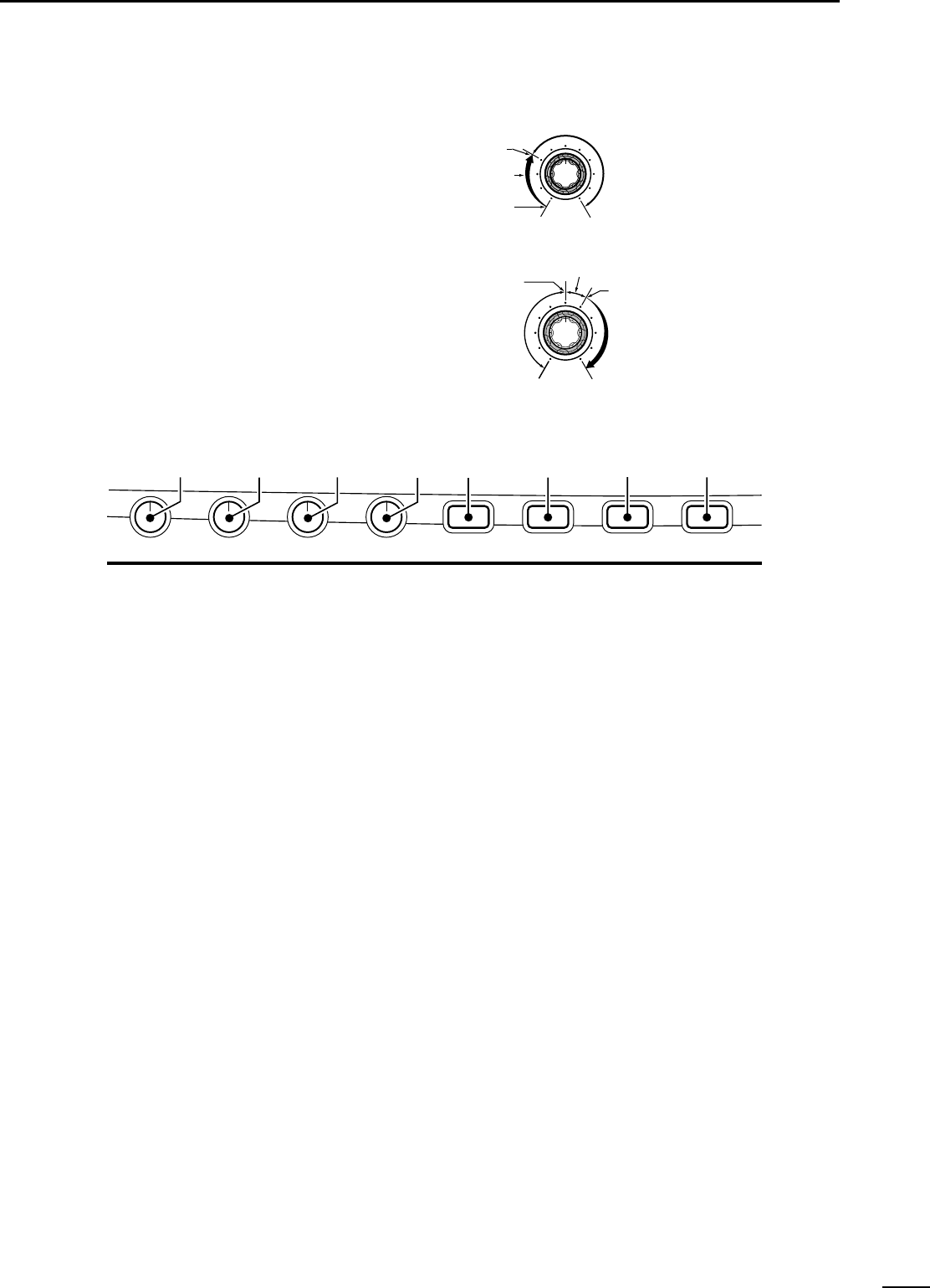
y ANTENNA TUNER SWITCH [TUNER] (p. 59)
➥ Turns the antenna tuner ON and OFF (bypass)
when pushed momentarily.
➥ Starts to tune the antenna manually when
pushed for 2 sec.
• When the tuner cannot tune the antenna, the tuning
circuit is bypassed automatically after 20 sec.
u ANTENNA SELECTOR SWITCH [ANT] (p. 71)
Toggles between the HF and 50 MHz antenna con-
nectors.
i NOISE REDUCTION LEVEL CONTROL [NR]
(p. 40)
Adjusts the noise reduction level when the noise re-
duction function is in use. Set for maximum read-
ability.
o AUDIO PEAK FILTER CONTROL [APF] (p. 20)
Varies the peak frequency of the audio peak filter to
pick out a CW signal from interference while the
APF function is ON.
!0 NOISE REDUCTION SWITCH [NR] (p. 40)
Toggles the noise reduction function ON and OFF.
Functions in SSB, CW and RTTY modes.
!1 AUDIO PEAK FILTER/AUTO NOTCH SWITCH
[APF/ANF]
➥ Toggles between the audio peak (p.20) and auto
notch (p. 40) functions.
• The audio peak filter functions in CW mode only; the
auto notch functions in SSB, FM and AM modes only.
• The APF or ANF indicator appear in the display de-
pending on which function is selected.
➥ When the APF indicator appears, push this
switch for 1 sec., one or more times to select 320
Hz, 160 Hz or 80 Hz bandwidths.
• Use the [APF] control to vary the peak frequency.
!2 AF CONTROL [AF] (inner control; p. 12)
Varies the audio output level from the speaker.