3.3Wärmeleistung / Leistungszahl bei B-5 / W55 1kW / ---2
1.Diese Angaben charakterisieren die Größe und die Leistungsfähigkeit der Anlage nach EN14511. Für wirtschaftliche und energetische Betrachtungen sind Bivalenzpunkt und
Regelung zu berücksichtigen. Dabei bedeuten z.B. B10 / W55: Wärmequellentemperatur 10°C und Heizwasser-Vorlauftemperatur 55°C.
2.2Principle of Operation.............................................................................................................................E-3
Any work on the heat pump may only be performed by an authorised and
qualified customer service.
ATTENTION!
Devices with 6kg refrigerant or more must be leak-proof tested yearly
according to ES842/2006.
ATTENTION!
The heat pump must not be tilted more than max. 45° (in either direction).
ATTENTION!
The transport securing device is to be removed prior to commissioning.
ATTENTION!
The heating system must be flushed prior to connecting the heat pump.
ATTENTION!
The supplied strainer must be fitted in the heating water inlet of the heat
pump in order to protect the condenser against the ingress of impurities.
ATTENTION!
The supplied strainer must be fitted in the heat source inlet of the heat
pump in order to protect the evaporator against the ingress of impurities.
ATTENTION!
The brine solution must contain at least 25% of an antifreeze agent on a
mono-ethylene glycol or propylene glycol basis and must be mixed prior
to filling.
ATTENTION!
The clockwise phase sequence must be observed when connecting the
load lines (the heat pump will deliver no output and will be very noisy
when the phase sequence is incorrect).
ATTENTION!
Commissioning is to be effected in accordance with the installation and
operating manual of the heat pump controller.
ATTENTION!
To prevent the accumulation of deposits (e.g. rust) we recommend using
a suitable corrosion protection system.
ATTENTION!
Disconnect all electrical circuits from the power supply before opening
the enclosure.
1.2Intended Use
This device is only intended for use as specified by the manufac-
turer. Any other use beyond that intended by the manufacturer is
prohibited. This includes the user's abiding by the manufacturer's
product brochures. Please refrain from tampering with or altering
the device.
1.3Legal Provisions and
Guidelines
This heat pump conforms to all relevant DIN/VDE regulations
and EU directives. For details refer to the EC Declaration of Con-
formity in the appendix.
The electrical connection of the heat pump must be performed
according to and conforming with all relevant VDE, EN and IEC
standards. Beyond that, the connection requirements of the local
utility companies have to be observed.
The heat pump is to be connected to the heat source system and
the heating or cooling system in accordance with all applicable
regulations.
ATTENTION!
Any work on the heat pump may only be performed by an authorised and
qualified customer service.
ATTENTION!
Devices with 6kg refrigerant or more must be leak-proof tested yearly
according to ES842/2006.
More information is available in the chapter Care / Cleaning.
1.4Energy-Efficient Use of the
Heat Pump
By operating this heat pump you contribute to the protection of
our environment. The heating or cooling system and the heat
source must be properly designed and dimensioned to ensure ef-
ficient operation. In particular, it is important to keep water flow
temperatures as low as possible. All energy consumers con-
nected should therefore be suitable for low flow temperatures. A
1K higher heating water temperature corresponds to an in-
crease in power consumption of approx. 2.5%. Low-temperature
heating systems with flow temperatures between 30°C and
50°C are optimally suited for energy-efficient operation.
www.dimplex.deE-3
English
3
2Purpose of the heat
pump
2.1Application
The brine-to-water heat pump is to be used exclusively for the
heating and cooling of heating water. It can be used in new or
previously existing heating systems. Brine is used as the heat
transfer medium in the heat source system. Borehole heat ex-
changers, ground heat collectors or similar systems can be used
as the heat source.
2.2Principle of Operation
Heating
The heat generated by the sun, wind and rain is stored in the
ground. This heat stored in the ground is collected at low temper-
ature by the brine circulating in the ground collector, ground coil
or similar device.
A circulating pump then conveys the warmed brine to the evapo-
rator of the heat pump. There, the heat is given off to the refriger-
ant in the refrigeration cycle. When so doing, the brine cools so
that it can again take up heat energy in the brine circuit.
The refrigerant is drawn in by the electrically driven compressor,
is compressed and “pumped” to a higher temperature level. The
electrical power needed to run the compressor is not lost in this
process, but most of the generated heat is transferred to the re-
frigerant.
Subsequently, the refrigerant is passed through the condenser
where it transfers its heat energy to the heating water. Based on
the thermostat setting, the heating water is thus heated to up to
60°C.
Cooling
The functions of the evaporator and the liquifier are reversed in
the “Cooling” operating mode.
The heating water gives up its heat to the refrigerant via the liqui-
fier which is now functioning as an evaporator. The refrigerant is
pumped to a higher temperature level using the compressor.
Heat passes into the brine via the liquifier (evaporator in heating
operation) and consequently into the ground.
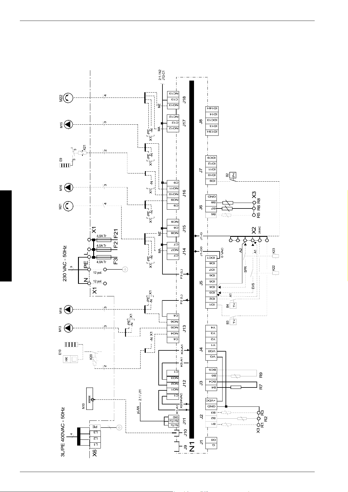
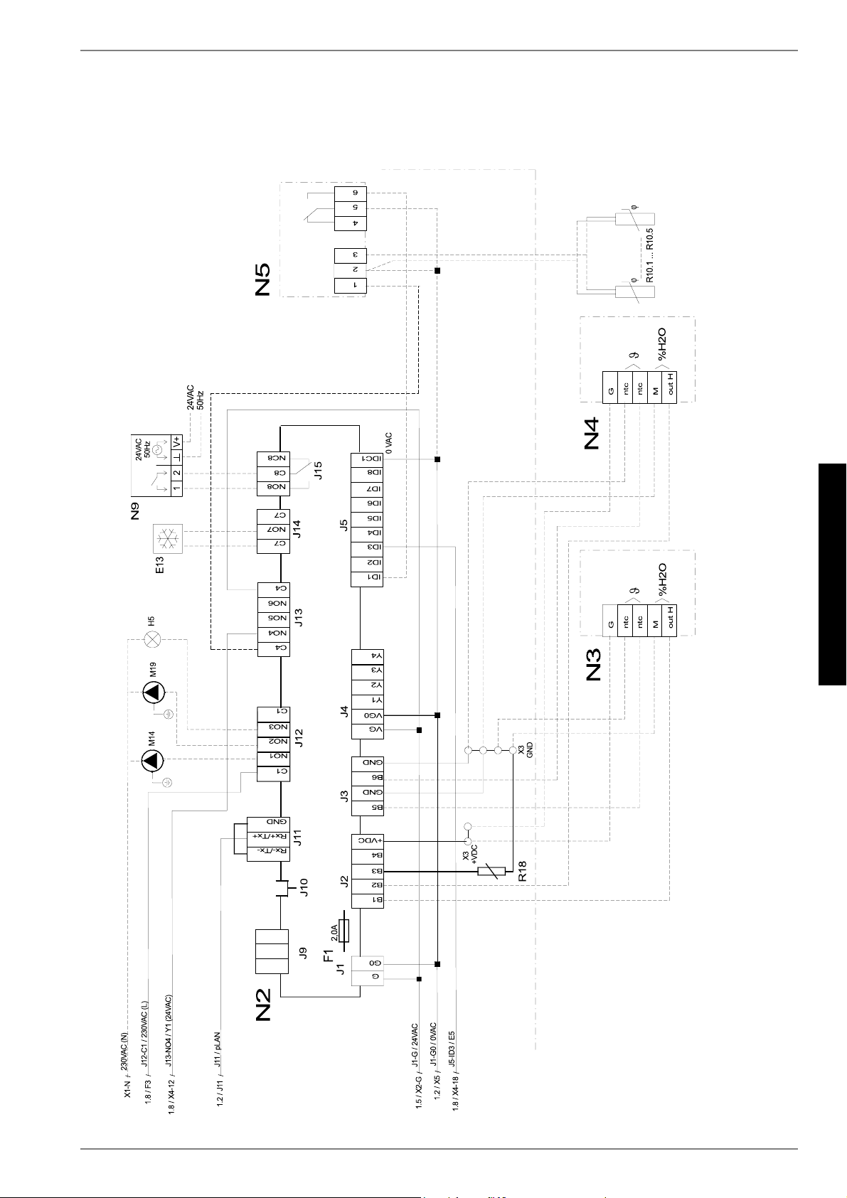
3Baseline Unit
The baseline unit consists of a heat pump, ready for connection,
for indoor installation, complete with sheet metal cabinet, control
box and integrated controller. The refrigerant circuit is hermeti-
cally sealed. It contains the Kyoto protocol approved refrigerant
R404A with a GWP value of 3260. It is CFC-free, does not de-
plete ozone and is non-flammable.
All components required for the operation of the heat pump are
located in the control box. A sensor for the external wall temper-
ature including mounting hardware as well as a strainer are sup-
plied with the heat pump. The voltage supply for the load and
control current must be provided by the customer.
The control wire of the brine pump (to be provided by the cus-
tomer) is to be connected to the control box. When so doing, a
motor protecting device is to be installed, if required.
The collector including the brine manifold must be provided by
the customer.
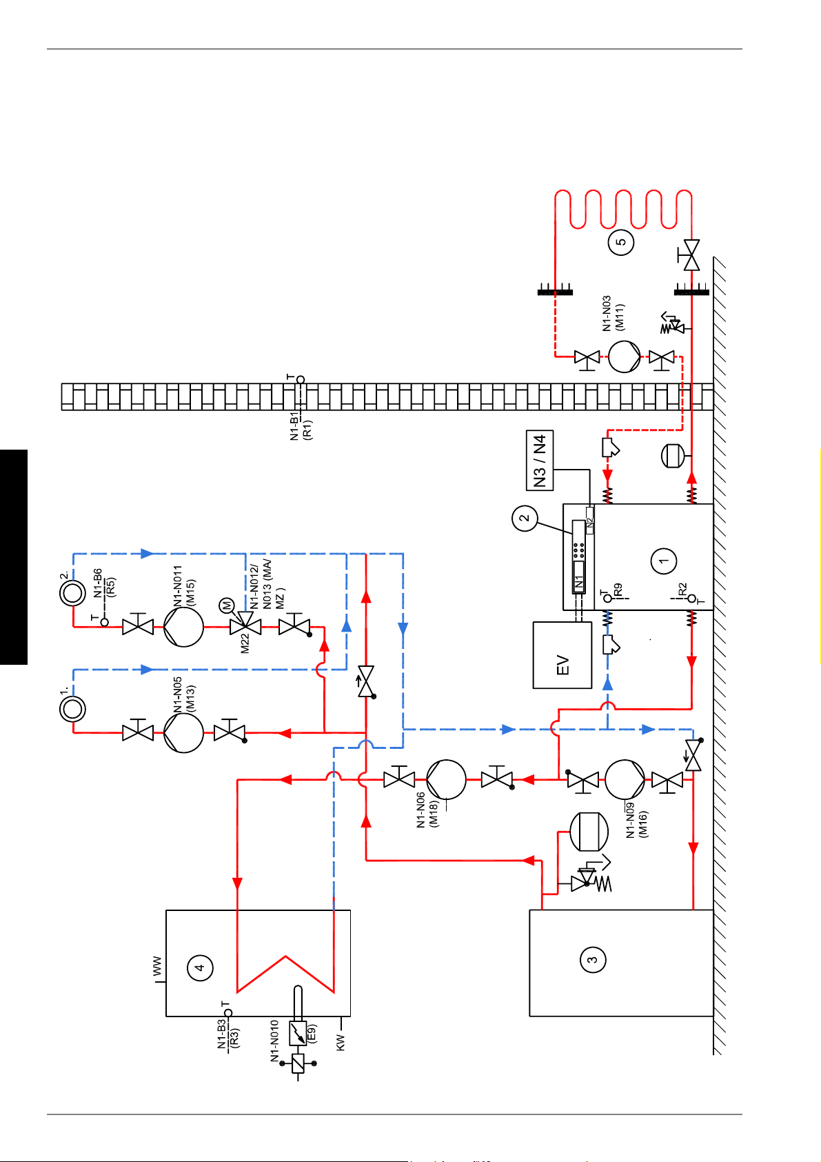
1)Control
2)Evaporator
3)Condenser
4)Compressor
5)Transport securing devices
6)Filter drier
E-4
English
4
4Accessories
4.1Connecting Flanges
The use of flat-sealing connecting flanges allows the unit, as an
option, to be connected by means of flanges.
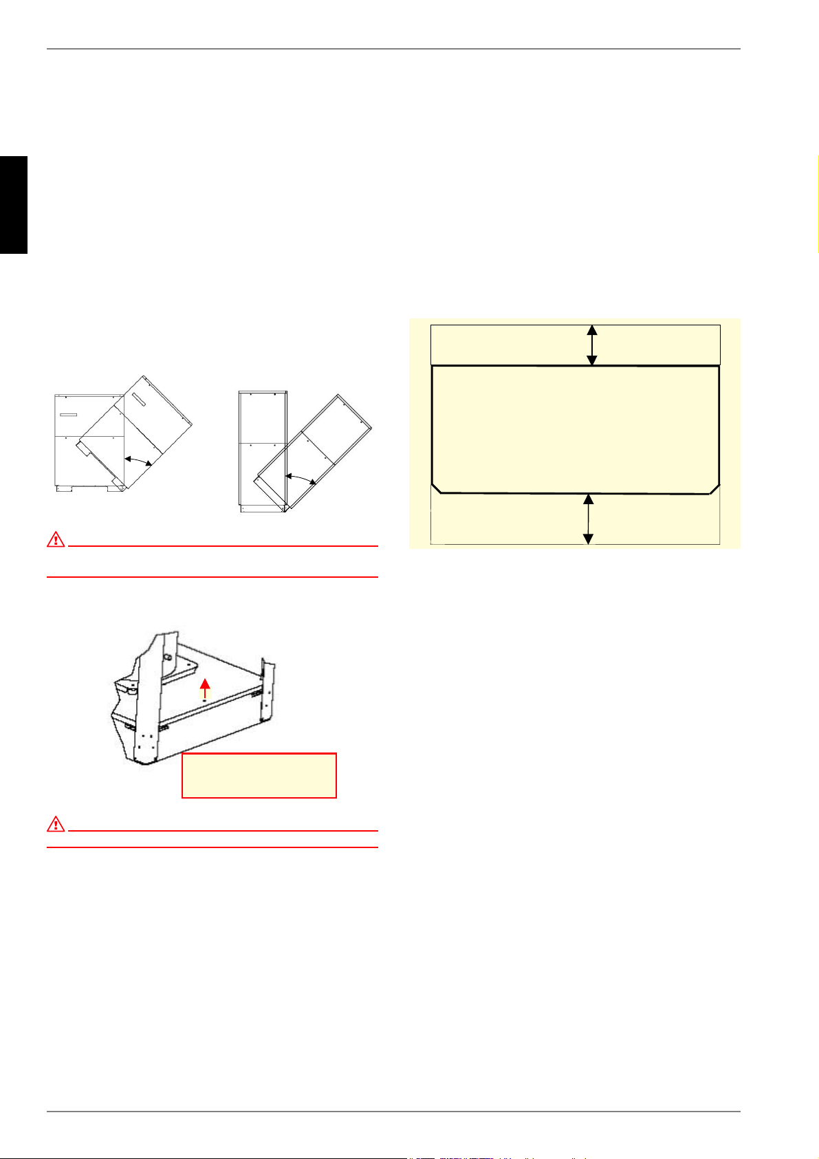
5Transport
For the transport by means of a hand truck or boiler trolley, posi-
tion the latter under the front end of the unit below the transport
security device.
For transport on a level surface, the unit can be lifted from the
rear or from the front by means of a lift truck or forklift. In this
case, the transport securing device is not imperative.
ATTENTION!
The heat pump must not be tilted more than max. 45° (in either direction).
After the transport, the transport securing device is to be re-
moved on either side at the bottom of the unit.
ATTENTION!
The transport securing device is to be removed prior to commissioning.
To remove the panelling, open the individual covers by unscrew-
ing the respective turn-lock fasteners and then gently tilting the
covers away from the device. Then lift them up out of the mount-
ings.
6Installation
6.1General Information
As a rule, the unit must be installed indoors on a level, smooth
and horizontal surface. The entire base frame should make full
contact with the surface in order to ensure adequate sound insu-
lation. Failing this, additional sound insulation measures may be-
come necessary.
The heat pump should be installed to allow easy maintenance/
service access. This is ensured if a clearance of approx. 1m in
front of the heat pump is maintained.
6.2Sound Emissions
The heat pump offers silent operation due to efficient sound insu-
lation. Any vibration transmission to the foundation or the heating
system can be largely prevented by internal sound decoupling
measures.
5HPRYHVFUHZLQ
WUDQVSRUWORFN
P
P
www.dimplex.deE-5
English
7.4
7Mounting
7.1General Information
The following connections need to be estab-lished on the heat
pump:
supply/return flow of the brine system
supply/return flow of the heating system
power supply
7.2Connection on Heating Side
ATTENTION!
The heating system must be flushed prior to connecting the heat pump.
Before completing the heat pump connections on the heating
water side, the heating installation must be flushed in order to re-
move any impurities that may be present, as well as residues of
sealing material, and the like. Any accumulation of deposits in
the condenser may result in a total failure of the heat pump.
ATTENTION!
The supplied strainer must be fitted in the heating water inlet of the heat
pump in order to protect the condenser against the ingress of impurities.
Once the installation on the heating side has been completed,
the heating system must be filled, de-aerated and pressure-
tested.
Heating water minimum flow rate
The heating water minimum flow rate through the heat pump
must be assured in all operating states of the heating system.
This can be accomplished, for example, by installing a differential
pressure-free manifold.
Frost protection for installations prone to frost
Provided the controller and heating circulating pumps are ready
for operation, the frost protection feature of the controller is ac-
tive. If the heat pump is taken out of service or in the event of a
power failure, the system has to be drained. In heat pump instal-
lations where a power failure cannot be readily detected (holiday
house), the heating circuit must contain a suitable antifreeze
product.
7.3Connection on Heat Source
Side
The following procedure must be observed when making the
connection:
Connect the brine line to the flow and return pipe of the heat
pump.
The hydraulic plumbing diagram must be observed here.
ATTENTION!
The supplied strainer must be fitted in the heat source inlet of the heat
pump in order to protect the evaporator against the ingress of impurities.
In addition, a microbubble deaerator must be installed in the heat
source system.
The brine liquid must be produced prior to charging the system.
The brine concentration must be at least 25%. Freeze protection
down to -14°C can thus be ensured.
Only antifreeze products on the basis of mono-ethylene glycol or
propylene glycol may be used.
The heat source system must be vented (de-aerated) and
checked for leaks.
ATTENTION!
The brine solution must contain at least 25% of an antifreeze agent on a
mono-ethylene glycol or propylene glycol basis and must be mixed prior
to filling.
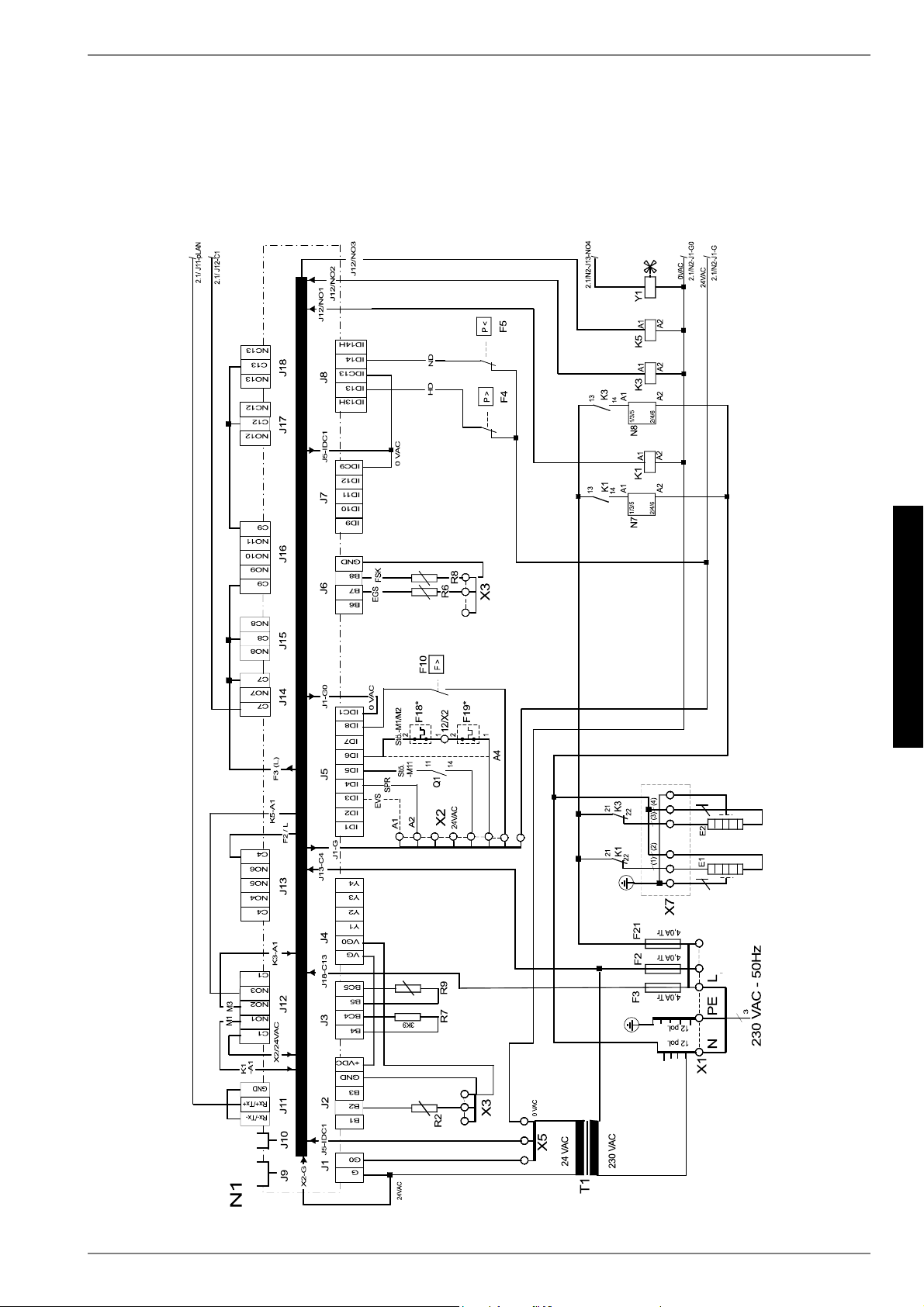
7.4Electrical Connection
The following electrical connections must be established on the
heat pump:
Connection of the control wire to terminals X1: L/N/PE in the
control box of the heat pump.
Connection of the load wire to terminals X5: L1/L2/L3/PE in
the control box of the heat pump.
Connection of the brine pump (to be supplied by the cus-
tomer) to terminal PE and pump contactor K5: 2/4/6 on the
control panel of the HP.
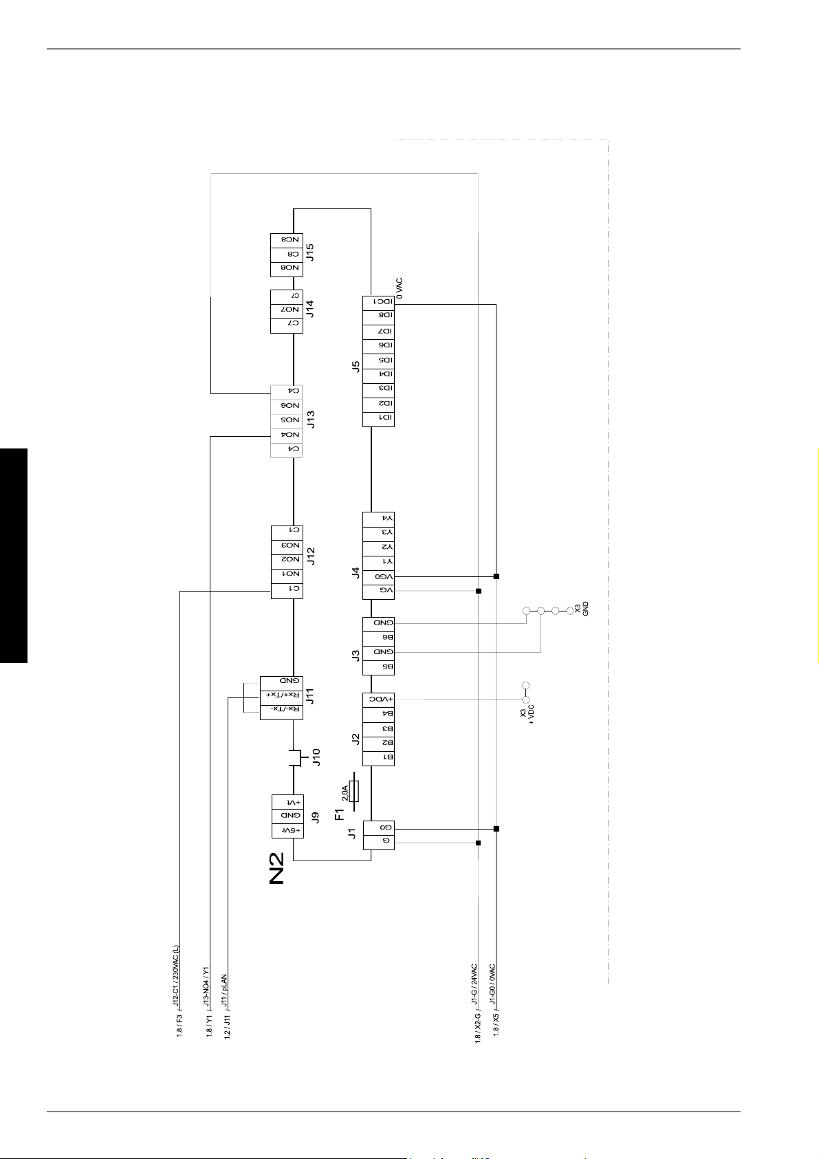
All electrical components required for the operation of the heat
pump are located in the control box.
For more detailed instructions concerning the connection and
functioning of the heat pump controller (e.g. the supplied external
wall sensor) please refer to the enclosed operating manual of the
controller.
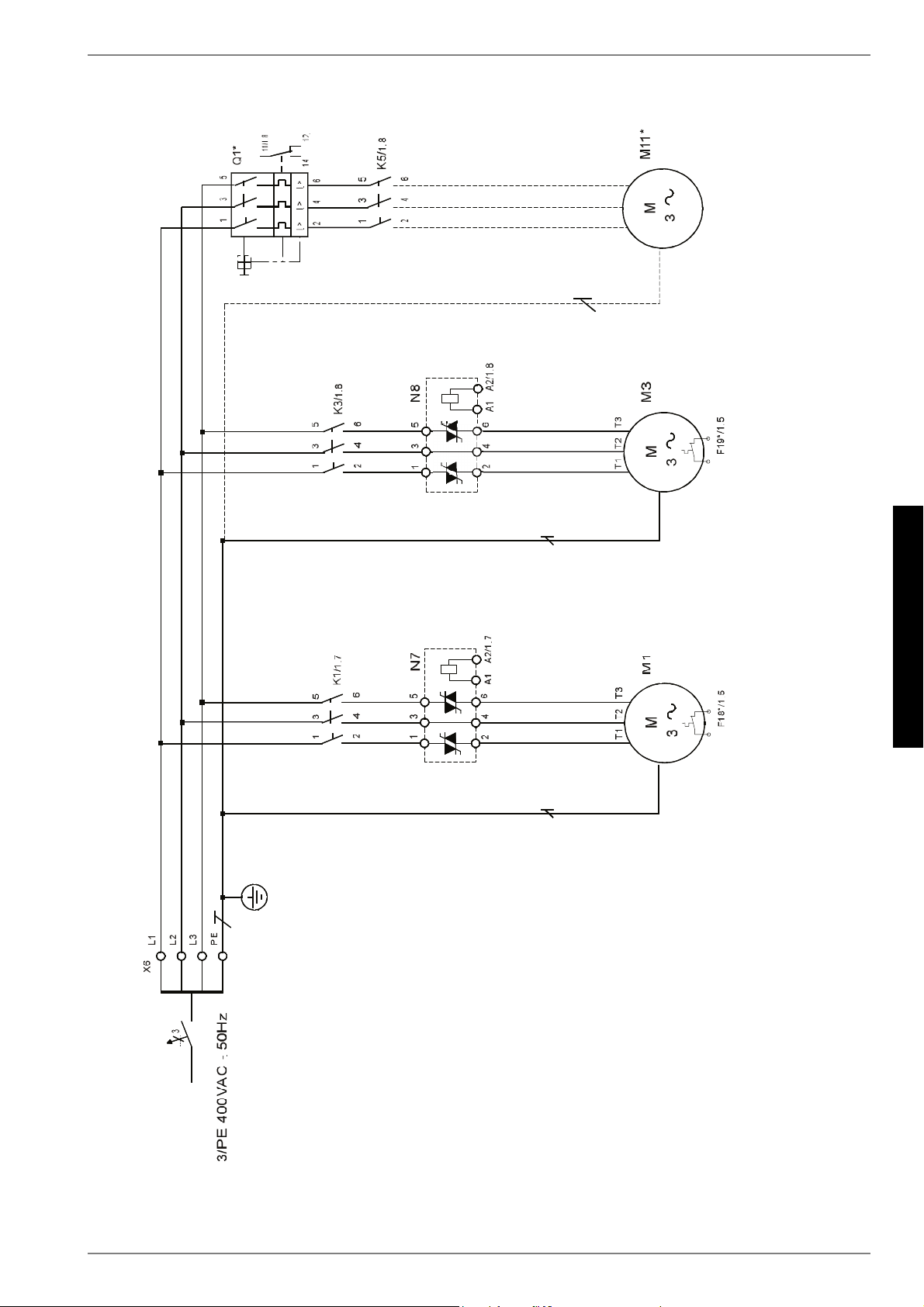
An automatic circuit-breaker with simultaneous tripping of all ex-
ternal conductors is to be provided in the load power supply. The
circuit-breaker must be an all-pole disconnect device with a con-
tact gap of at least 3mm. The same applies to any additional dis-
able contactors that may be required, e.g. during shut-off periods
imposed by the utility company. The required cross-sectional
area of the conductors is to be selected according to the power
consumption of the heat pump, the technical connection require-
ments of the relevant utility company and all applicable regula-
tions. Power consumption data of the heat pump is provided in
the product literature and on the nameplate. The terminals are
designed for a max. conductor cross-section of 35mm².
ATTENTION!
The clockwise phase sequence must be observed when connecting the
load lines (the heat pump will deliver no output and will be very noisy
when the phase sequence is incorrect).
The power cable must be run through the guide tubes, inserted
into the side of the control box and secured by means of the
strain relief.
E-6
English
8
8Commissioning
8.1General Information
To ensure proper commissioning it should be carried out by a
customer service authorised by the manufacturer. This will lead,
under certain circumstances, to an extension of the warranty pe-
riod (cf. Warranty). Start-up should be carried out in heating op-
eration.
8.2Preparatory Steps
Prior to commissioning, the following items need to be checked:
All connections of the heat pump must have been made as
described in Chapter 7.
The heat source system and the heating circuit must have
been filled and checked.
The strainer must have been fitted in the sole inlet of the
heat pump.
In the brine and heating circuits all valves that might impair
the proper flow must be open.
The settings of the heat pump controller must be adapted to
the heating installation in accordance with the instructions
contained in the controller's operating manual.
8.3Commissioning Procedure
The start-up of the heat pump is effected via the heat pump con-
troller.
ATTENTION!
Commissioning is to be effected in accordance with the installation and
operating manual of the heat pump controller.
Any malfunctions occurring during operation are displayed on the
heat pump controller and can be corrected as described in the
operating manual of the heat pump controller.
9Care/Cleaning
9.1Care
The heat pump is maintenance-free. To prevent malfunctions
due to sediments in the heat exchangers, care must be taken
that no im-purities can enter the heat source system and the
heating installation. In the event that operating malfunctions due
to contamination occur nevertheless, the system should be
cleaned as described below.
9.2Cleaning of Heating Side
ATTENTION!
The supplied strainer must be fitted in the heat source inlet of the heat
pump in order to protect the evaporator against the ingress of impurities.
The ingress of oxygen into the heating water circuit, in particular
if it contains steel components, may result in the formation of ox-
idation products (rust). These can enter the heating system via
valves, circulating pumps or plastic tubing. It is therefore impor-
tant - in particular with respect to the piping of underfloor heating
systems - that the installation be executed in a diffusion-proof
manner.
ATTENTION!
To prevent the accumulation of deposits (e.g. rust) we recommend using
a suitable corrosion protection system.
In the case of severe contamination leading to a reduction in the
performance of the condenser in the heat pump, the system must
be cleaned by a heating technician.
Based on current knowledge, we recommend cleaning with a 5%
phosphoric acid solution or, in the case that cleaning needs to be
performed more frequently, with a 5% formic acid solution.
In either case, the cleaning fluid should be at room temperature.
It is recommended that the heat exchanger be cleaned in the di-
rection opposite to the normal flow direction.
To prevent acidic cleaning agents from entering the circuit of the
heating installation we recommend that the flushing device be fit-
ted directly to the supply and return lines of the condenser of the
heat pump.
Thereafter the system must be thoroughly flushed using appro-
priate neutralising agents in order to prevent any damage caused
by cleaning agent residues that may still be present in the sys-
tem.
All acids must be used with great care, all relevant regulations of
the employers' liability insurance associations must be adhered
to.
If in doubt, contact the manufacturer of the chemicals!
9.3Cleaning of Heat Source Side
ATTENTION!
The supplied strainer must be fitted in the heat source inlet of the heat
pump in order to protect the evaporator against the ingress of impurities.
The filter screen of the strainer should be cleaned one day after
commissioning, thereafter every week. If no more contamination
can be noticed any more, the strainer filter can be removed in
order to reduce pressure losses.
www.dimplex.deE-7
English
11
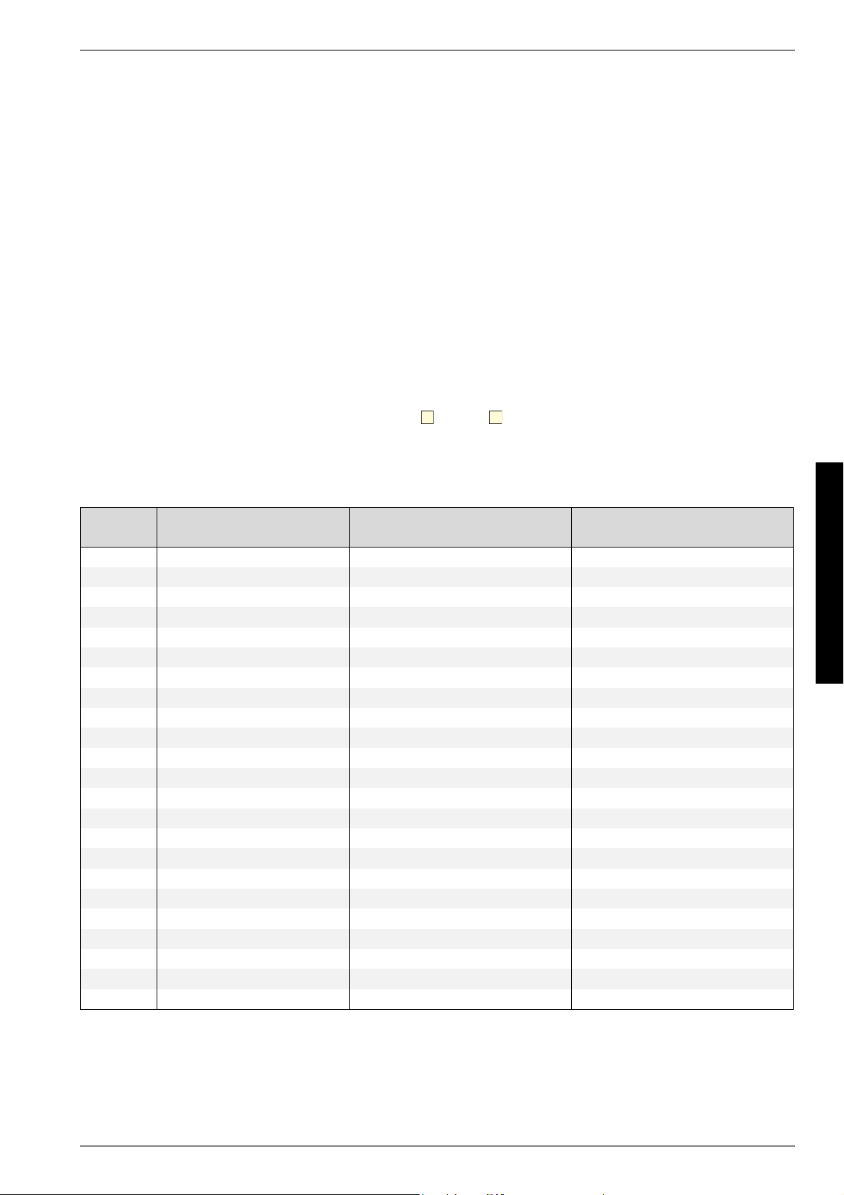
9.4Maintenance
Devices with a minimum of 3kg refrigerant, or hermetically
sealed devices with a minimum of 6kg refrigerant must be leak-
proof tested yearly by the operator according to ES842/2006.
The leak-proof testing is to be documented and archived for a
minimum of 5years. The test is to be carried out by certified per-
sonnel only according to ES1516/2007. The attached table can
be used as a basis for the documentation.
10Malfunctions /
Troubleshooting
This heat pump is a quality product and designed for trouble- and
maintenance-free operation. In the event that a malfunction oc-
curs nevertheless, it will be indicated on the display of the heat
pump controller. Simply consult the Malfunctions and Trouble-
shooting table contained in the in-stallation and operating man-
ual of the heat pump controller (manager).
If you cannot correct the malfunction yourself, please contact the
after-sales service agent in charge.
ATTENTION!
All work on the heat pump may only be performed by an authorised an
qualified after-sales service.
ATTENTION!
Disconnect all electrical circuits from the power supply before opening
the enclosure.
11Decommissioning /
Disposal
Before removing the heat pump, disconnect the unit from the
power source and close all valves.
Environment-relevant requirements regarding the recovery, re-
cycling and disposal of service fuels and components in accord-
ance with all relevant standards must be adhered to. Particular
attention must hereby be paid to the proper disposal of refriger-
ants and refrigeration oils.
E-8
English
12
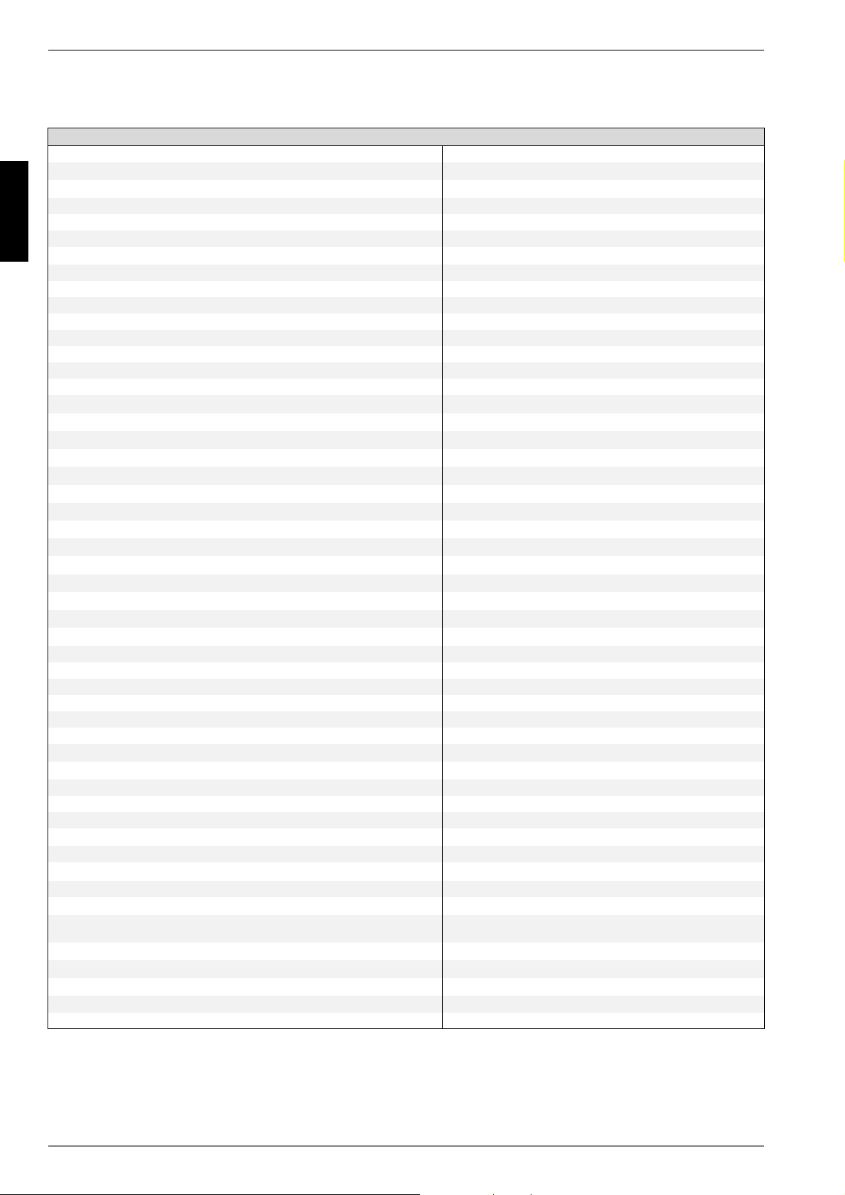
12Device Information
Device information for brine-to-water heat pumps (heating only)
1Type and order code SI 75ZSR
2Design
2.1ModelReversible
2.2Degree of protection according to EN 60 529 IP 21
2.3Installation locationIndoors
3Performance data
3.1Operating temperature limits:
Heating water flow°CUp to 55
Cooling, flow°C+7 to +20
Brine (heat source, heating)°C-5 to +25
Brine (heat sink, cooling)°C+5 to +30
AntifreezeMonoethylene glycol
Minimum brine concentration (-13 °C freezing temperature)25%
3.2Temperature spread
of heating water (flow/return flow) at B0 / W35K5
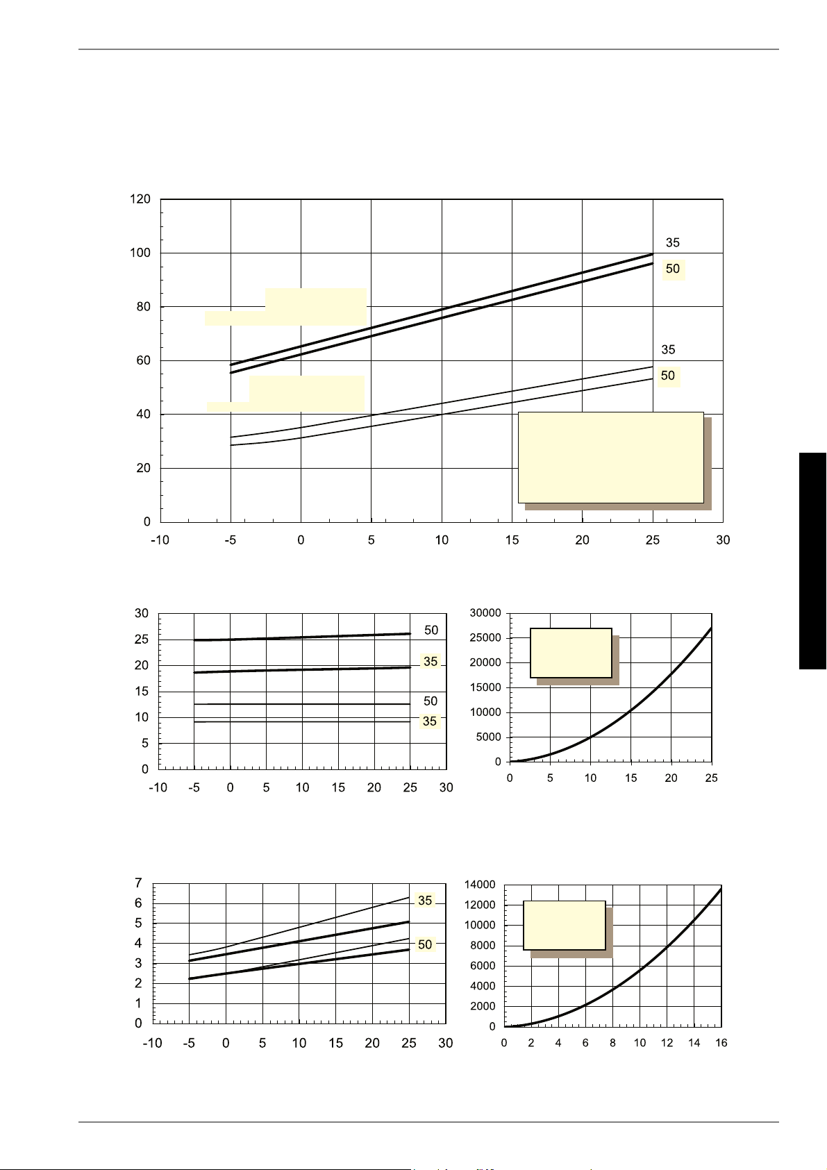
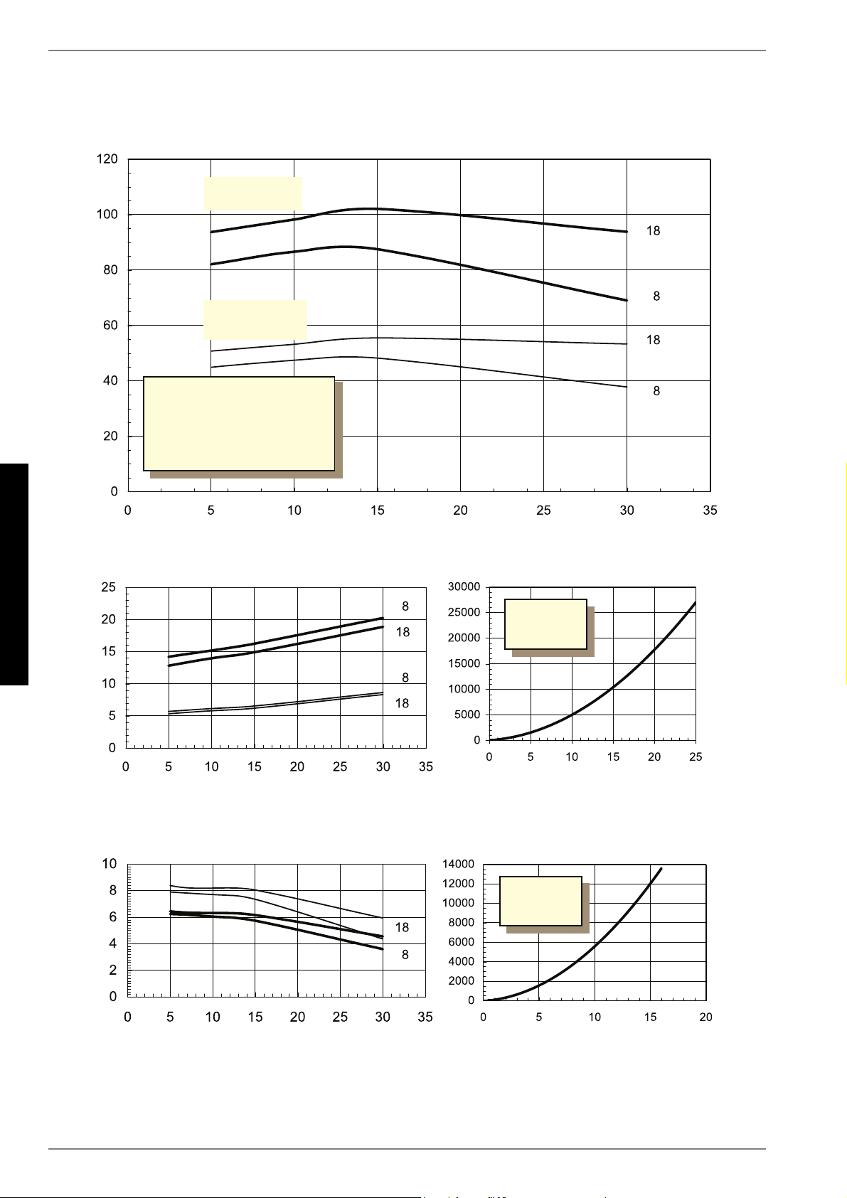
3.3Heat output / COPat B-5 / W55 1kW / ---2
1.This data indicates the size and capacity of the system according to EN14511. For an analysis of the economic and energy efficiency of the system, both the bivalence point and the regulation
should also be taken into consideration. The specified values, e.g. B10 / W55, have the following meaning: Heat source temperature 10 °C and heating water flow temperature 55 °C.
3.1Appareil de base.....................................................................................................................................F-3
1.Ces indications caractérisent la taille et le rendement de l’installation selon EN14511. Le point de bivalence et la régulation sont à prendre en compte pour des considérations
économiques et énergétiques. Ici, B10 / W55 signifie par ex.: température source de chaleur 10°C et température départ eau de chauffage 55°C.
Gebruikershandleiding.com neemt misbruik van zijn services uitermate serieus. U kunt hieronder aangeven waarom deze vraag ongepast is. Wij controleren de vraag en zonodig wordt deze verwijderd.
Product:
Spelregels forum
Om tot zinvolle vragen te komen hanteren wij de volgende spelregels:
lees eerst de handleiding door;
controleer of uw vraag al eerder door iemand anders is gesteld;
probeer uw vraag zo duidelijk mogelijk te stellen;
heeft u een probleem en al geprobeerd om dit op te lossen, vermeld dit erbij aub;
heeft u een oplossing gekregen van een bezoeker dan horen wij dat graag in dit forum;
wilt u een reactie geven op een vraag of antwoord, gebruik dan niet dit formulier maar klik op de knop 'reageer op deze vraag';
uw vraag wordt direct op de website gezet; vermijd daarom persoonlijke gegevens in te vullen;
Belangrijk! Als er een antwoord wordt gegeven op uw vraag, dan is het voor de gever van het antwoord nuttig om te weten als u er wel (of niet) mee geholpen bent! Wij vragen u dus ook te reageren op een antwoord.
Belangrijk! Antwoorden worden ook per e-mail naar abonnees gestuurd. Laat uw emailadres achter op deze site, zodat u op de hoogte blijft. U krijgt dan ook andere vragen en antwoorden te zien.
Abonneren
Abonneer u voor het ontvangen van emails voor uw Dimplex SI 75ZSR bij:
nieuwe vragen en antwoorden
nieuwe handleidingen
U ontvangt een email met instructies om u voor één of beide opties in te schrijven.
Ontvang uw handleiding per email
Vul uw emailadres in en ontvang de handleiding van Dimplex SI 75ZSR in de taal/talen: Duits, Engels, Frans als bijlage per email.
De handleiding is 2.37 mb groot.
U ontvangt de handleiding per email binnen enkele minuten. Als u geen email heeft ontvangen, dan heeft u waarschijnlijk een verkeerd emailadres ingevuld of is uw mailbox te vol. Daarnaast kan het zijn dat uw internetprovider een maximum heeft aan de grootte per email. Omdat hier een handleiding wordt meegestuurd, kan het voorkomen dat de email groter is dan toegestaan bij uw provider.
Stel vragen via chat aan uw handleiding
Stel uw vraag over deze PDF
Uw handleiding is per email verstuurd. Controleer uw email
Als u niet binnen een kwartier uw email met handleiding ontvangen heeft, kan het zijn dat u een verkeerd emailadres heeft ingevuld of dat uw emailprovider een maximum grootte per email heeft ingesteld die kleiner is dan de grootte van de handleiding.
Er is een email naar u verstuurd om uw inschrijving definitief te maken.
Controleer uw email en volg de aanwijzingen op om uw inschrijving definitief te maken
U heeft geen emailadres opgegeven
Als u de handleiding per email wilt ontvangen, vul dan een geldig emailadres in.
Uw vraag is op deze pagina toegevoegd
Wilt u een email ontvangen bij een antwoord en/of nieuwe vragen? Vul dan hier uw emailadres in.