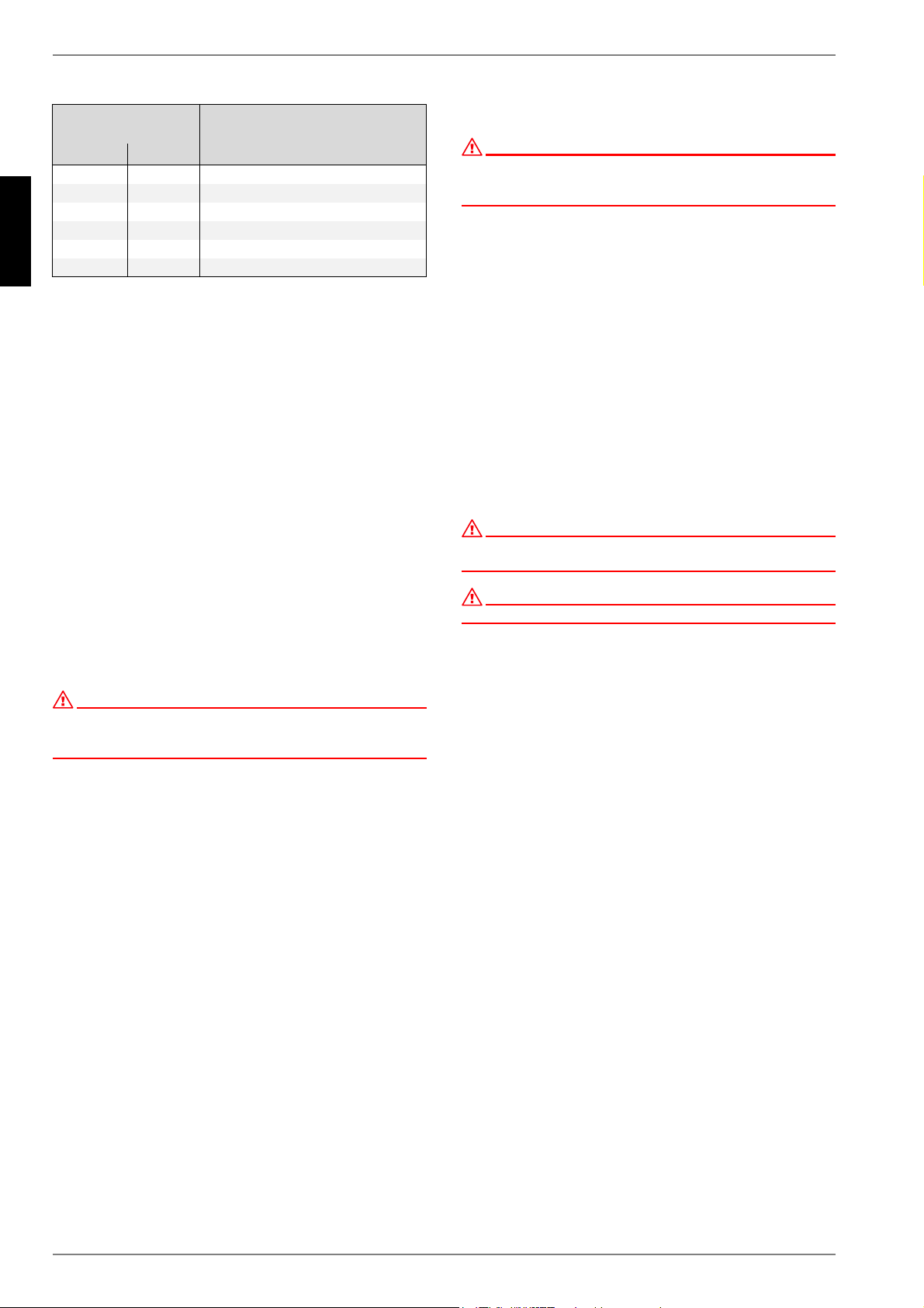
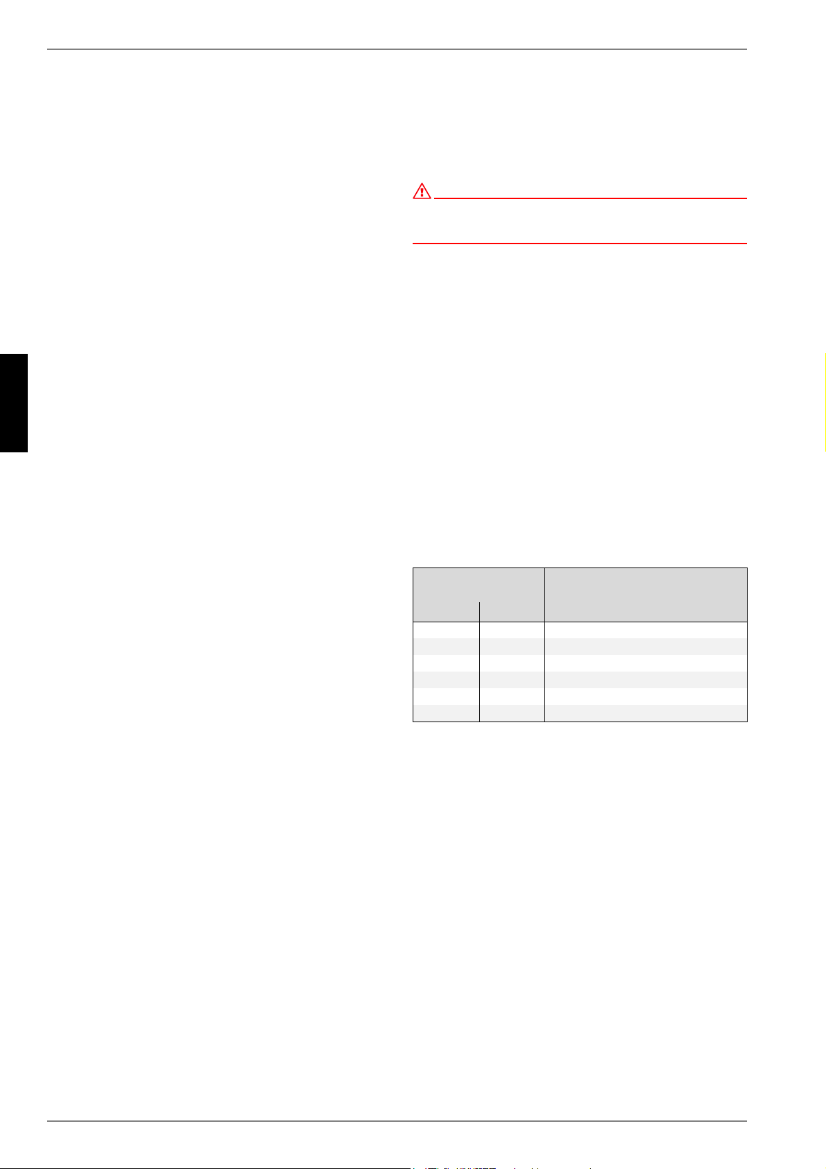
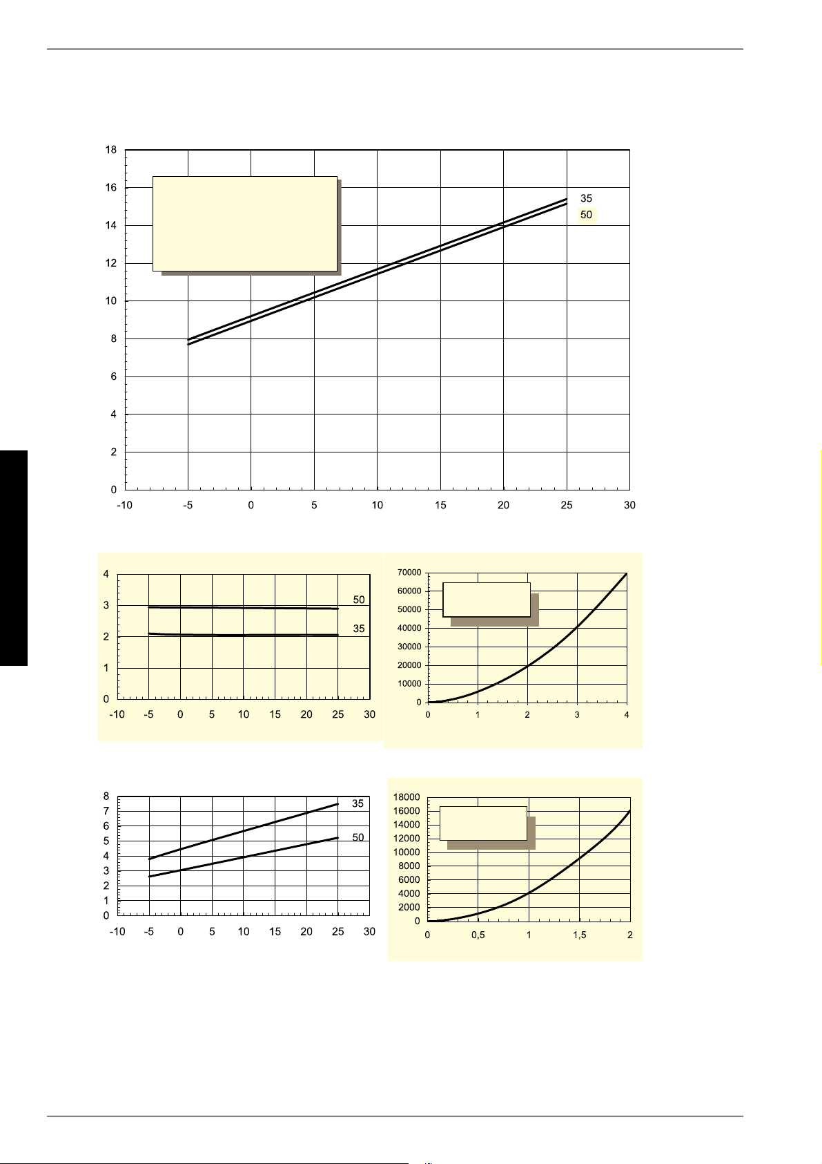
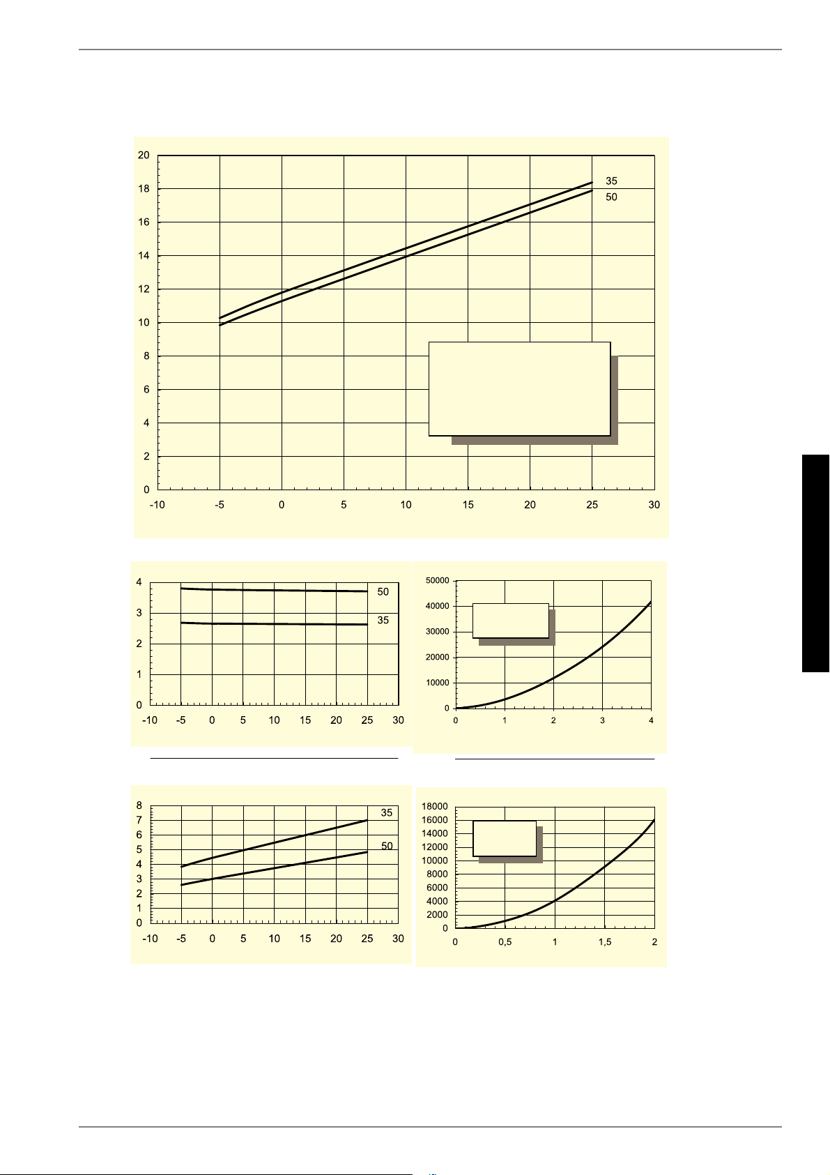
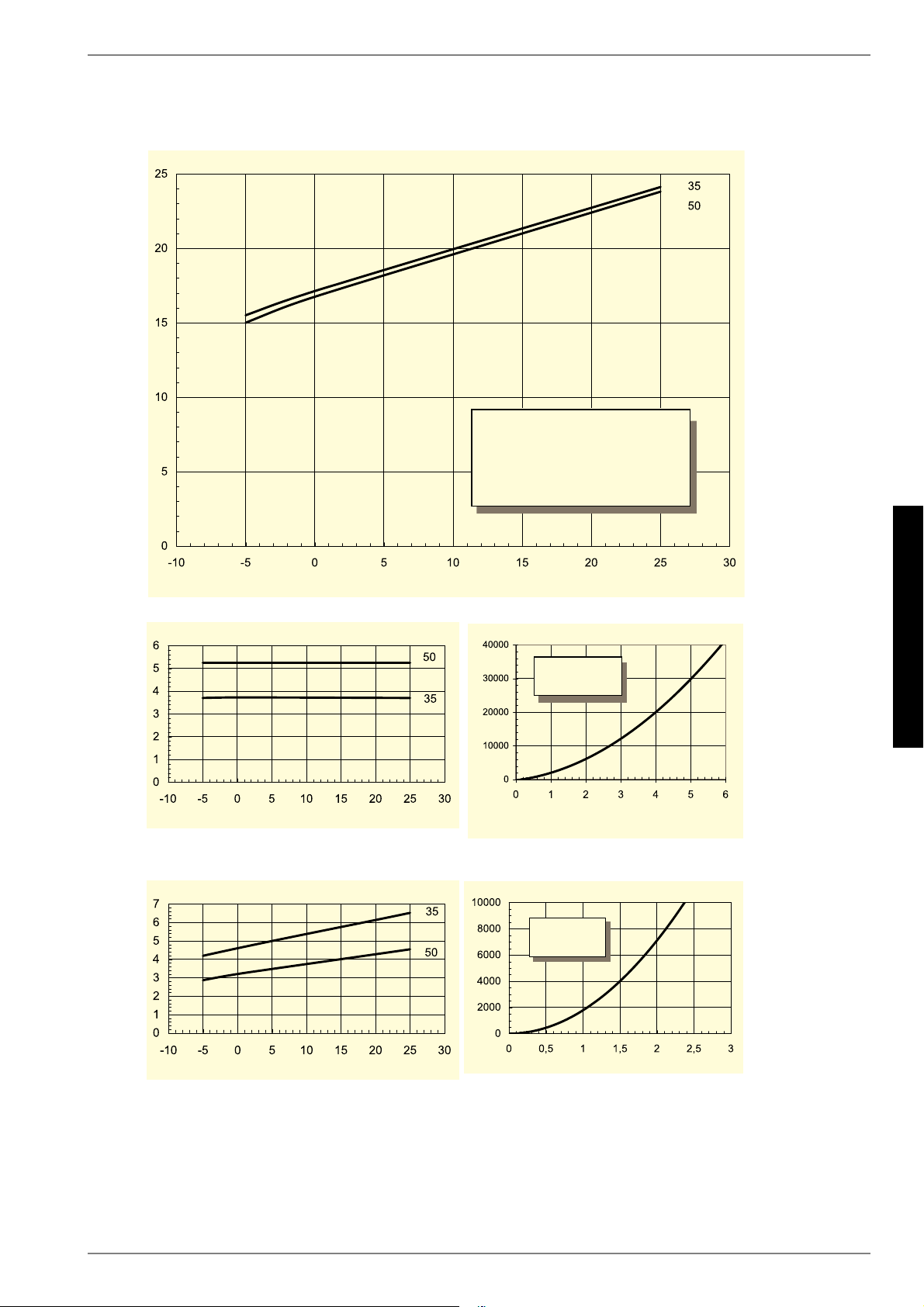
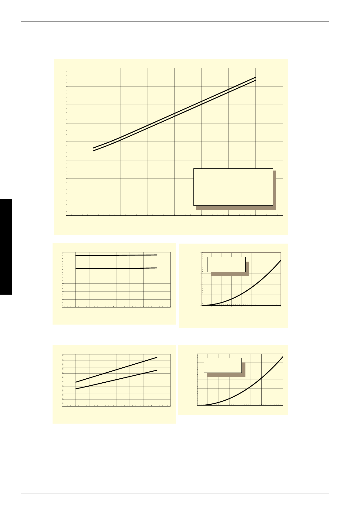
1.Diese Angaben charakterisieren die Größe und die Leistungsfähigkeit der Anlage. Für wirtschaftliche und energetische Betrachtungen sind Bivalenzpunkt und Regelung zu be-
rücksichtigen. Dabei bedeuten z.B. B10/ W55: Wärmequellentemperatur 10°C und Heizwasser-Vorlauftemperatur 55°C.
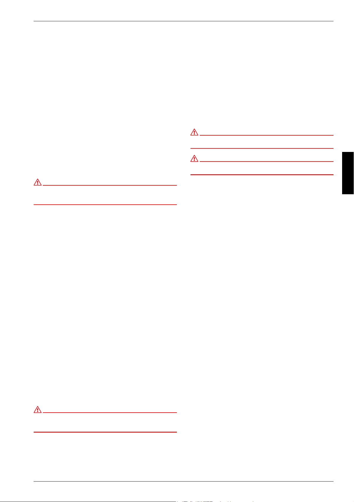
6Entspricht den europäischen Sicherheitsbestimmungen333
7Sonstige Ausführungsmerkmale
7.1Wasser im Gerät gegen Einfrieren geschützt 4jajaja
7.2Leistungsstufen111
7.3Regler intern / externinterninternintern
1.Diese Angaben charakterisieren die Größe und die Leistungsfähigkeit der Anlage. Für wirtschaftliche und energetische Betrachtungen sind Bivalenzpunkt und Regelung zu be-
rücksichtigen. Dabei bedeuten z.B. B10/ W55: Wärmequellentemperatur 10°C und Heizwasser-Vorlauftemperatur 55°C.
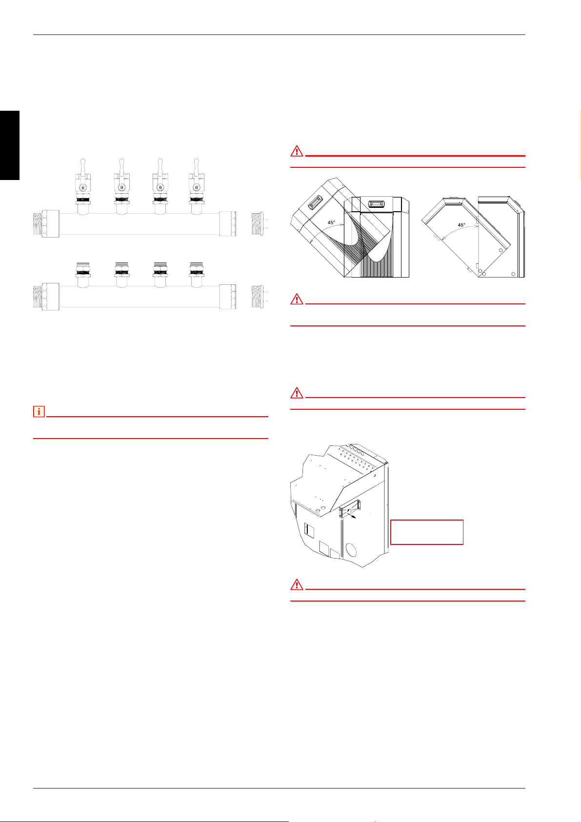
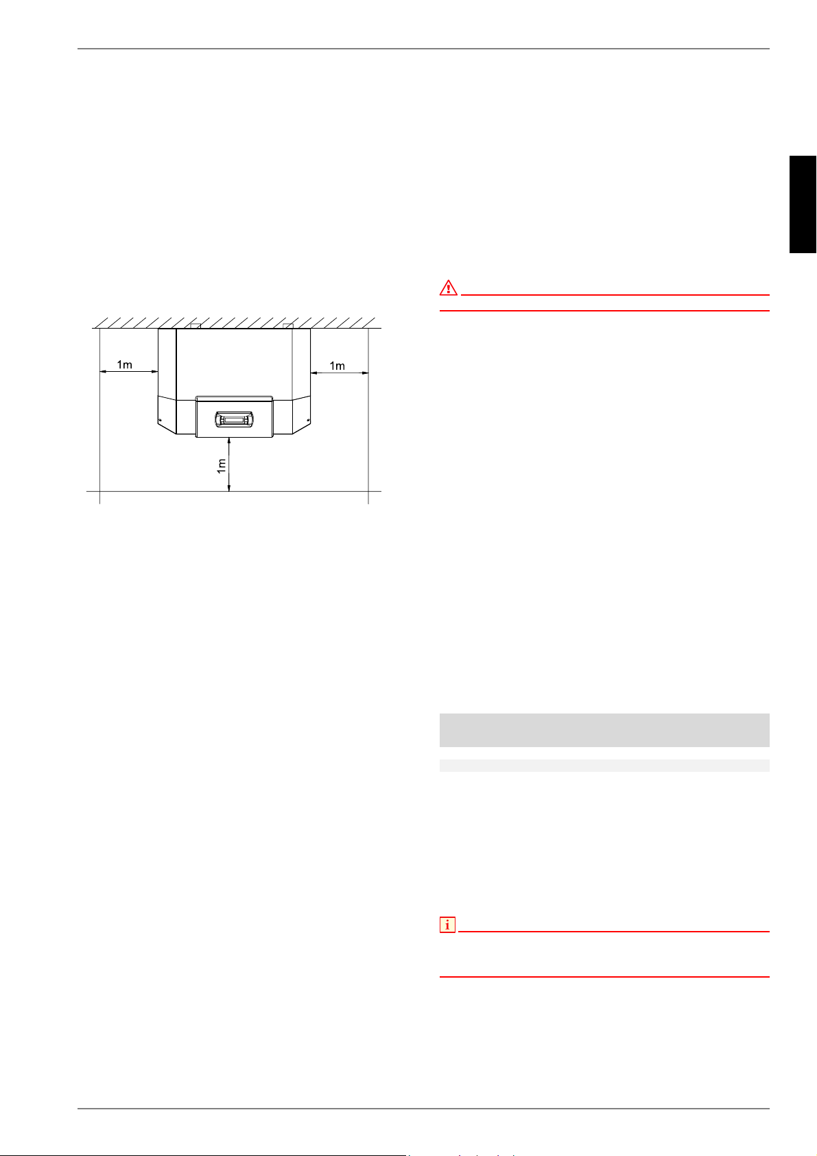
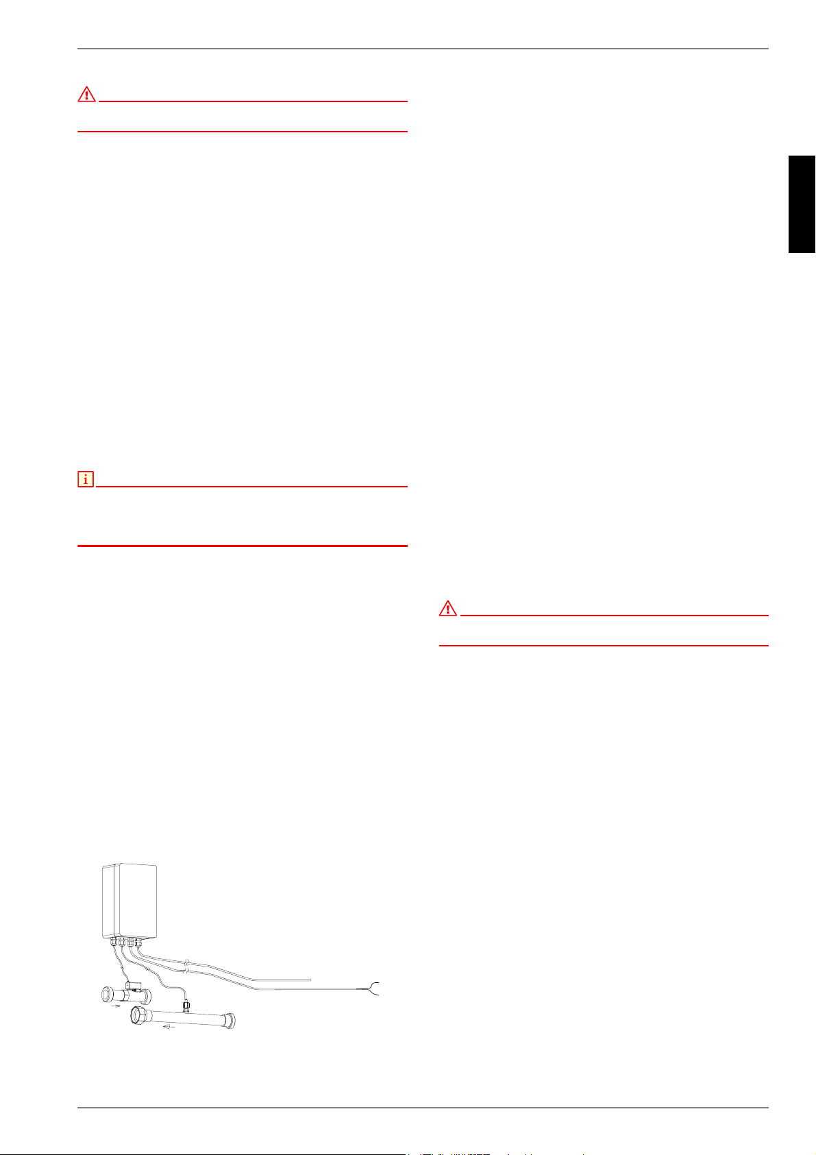
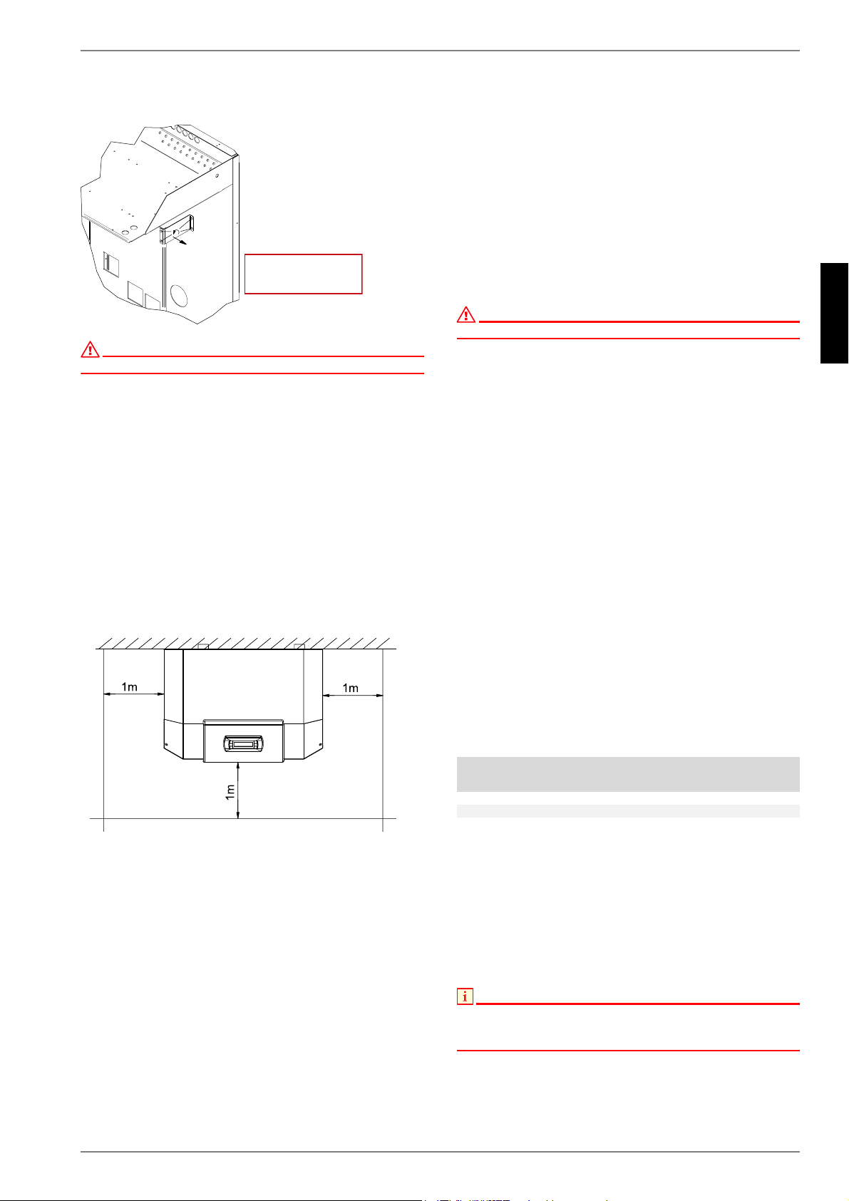
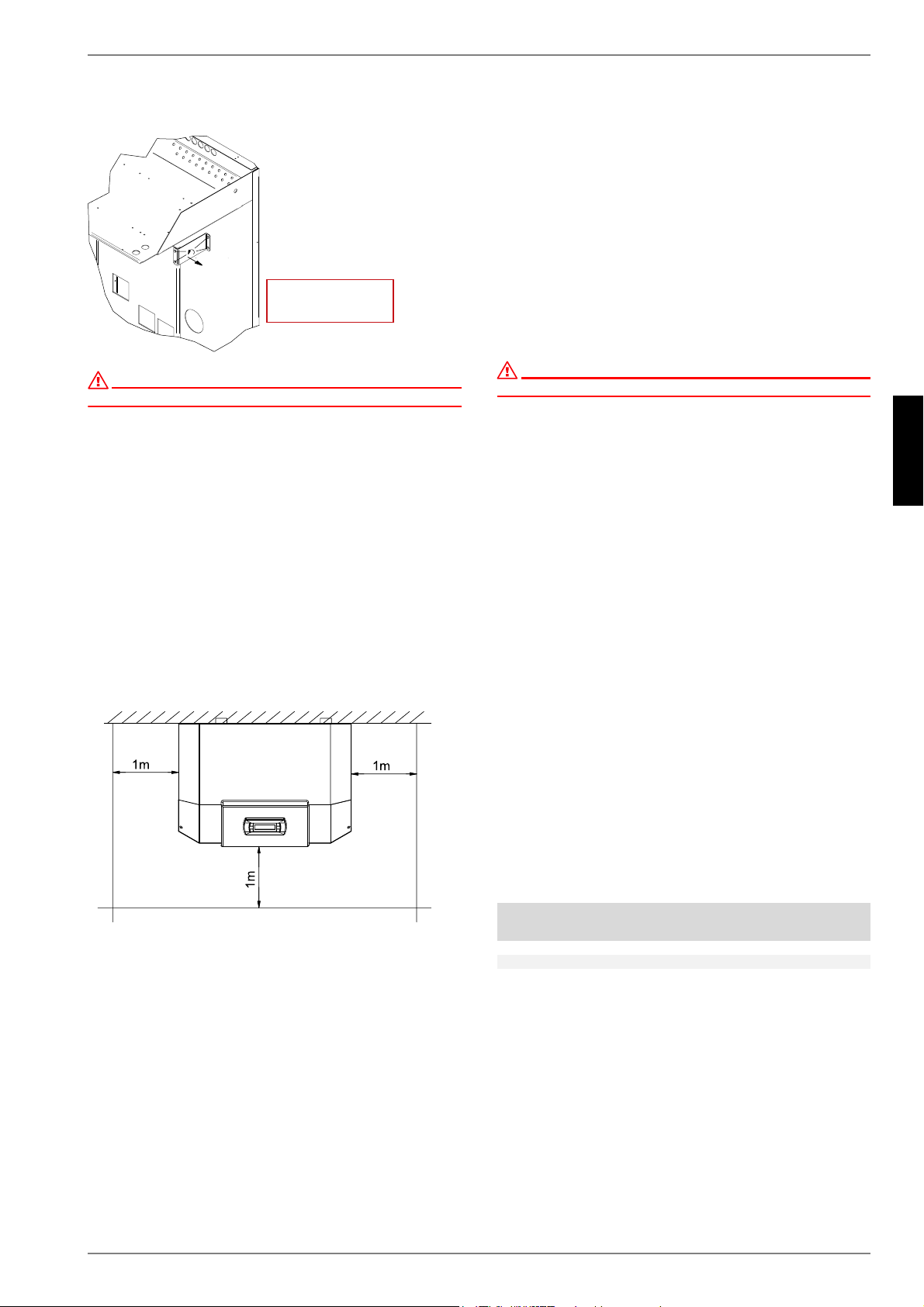
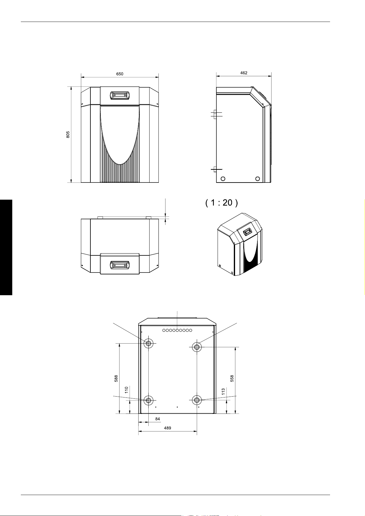
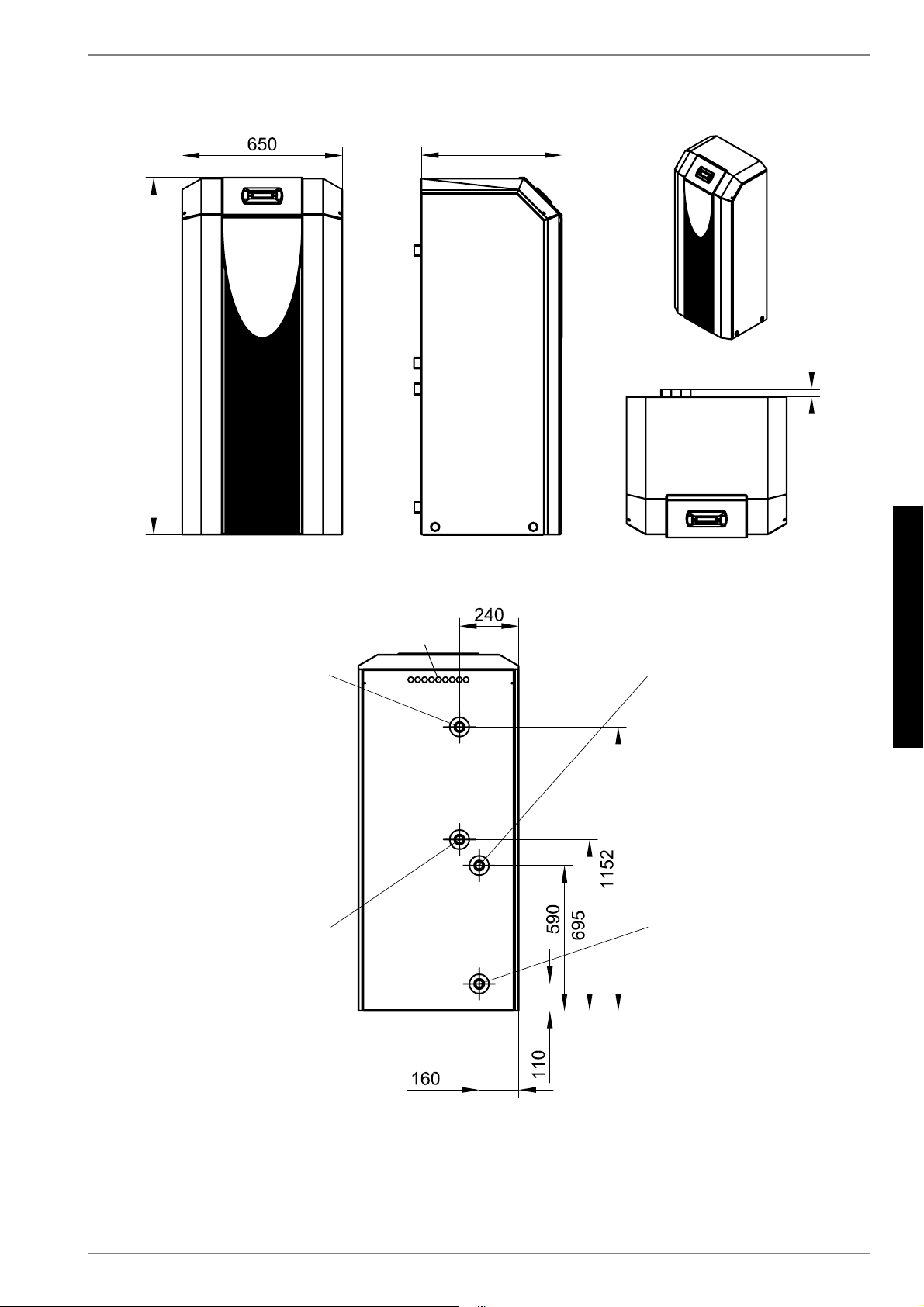
2.Beachten Sie, dass der Platzbedarf für Rohranschluss, Bedienung und Wartung größer ist.
3.siehe CE-Konformitätserklärung
4.Die Heizungs-Umwälzpumpe und der Regler der Wärmepumpe müssen immer betriebsbereit sein.
www.dimplex.deD-13
Deutsch
14
14Garantieurkunde
Die nachstehenden Bedingungen, die Voraussetzungen und
Umfang unserer Garantieleistung umschreiben, lassen die Ge-
währleistungsverpflichtungen des Verkäufers aus dem Kaufver-
trag mit dem Endabnehmer unberührt. Für die Geräte leisten wir
Garantie gemäß nachstehenden Bedingungen:
Wir beheben unentgeltlich nach Maßgabe der folgenden Bedin-
gungen Mängel am Gerät, die nachweislich auf einem Material-
und/oder Herstellungsfehler beruhen, wenn sie uns unverzüglich
nach Feststellung und innerhalb von 24 Monaten nach Lieferung
an den Erstendabnehmer gemeldet werden. Bei gewerblichem
Gebrauch innerhalb von 12 Monaten. Zeigt sich der Mangel in-
nerhalb von 6 Monaten ab Lieferung und liegt eine erfolgreiche
Inbetriebnahme (Heizungs-Wärmepumpe und zentrale Woh-
nungslüftungsgeräte) durch den autorisierten Systemtechnik-
Kundendienst vor, wird vermutet, dass es sich um einen Mate-
rial- oder Herstellungsfehler handelt.
Dieses Gerät fällt nur dann unter diese Garantie, wenn es von
einem Unternehmer in einem der Mitgliedstaaten der Eur-
opäischen Union gekauft wurde, es bei Auftreten des Mangels in
Deutschland betrieben wird und Garantieleistungen auch in
Deutschland erbracht werden können.
Die Behebung der von uns als garantiepflichtig anerkannter
Mängel geschieht dadurch, dass die mangelhaften Teile unent-
geltlich nach unserer Wahl instandgesetzt oder durch einwand-
freie Teile ersetzt werden. Durch Art oder Ort des Einsatzes des
Gerätes oder schlechte Zugänglichkeit des Gerätes bedingte au-
ßergewöhnliche Kosten der Mängelbeseitigung werden nicht
übernommen. Der freie Gerätezugang muss durch den Endab-
nehmer gestellt werden. Ausgebaute Teile, die wir zurückneh-
men, gehen in unser Eigentum über. Die Garantiezeit für Nach-
besserungen und Ersatzteile endet mit dem Ablauf der
ursprünglichen Garantiezeit für das Gerät. Die Garantie erstreckt
sich nicht auf leicht zerbrechliche Teile, die den Wert oder die
Gebrauchstauglichkeit des Gerätes nur unwesentlich beein-
trächtigen. Es ist jeweils der Original-Kaufbeleg mit Kauf- und/
oder Lieferdatum vorzulegen.
Eine Garantieleistung entfällt, wenn vom Endabnehmer oder
einem Dritten die entsprechenden VDE-Vorschriften, die Bestim-
mungen der örtlichen Versorgungsunternehmen oder unsere
Montage- und Gebrauchsanweisung sowie die in den Projektie-
rungsunterlagen enthaltenen Hinweise oder Einbindungssche-
men nicht beachtet worden sind oder wenn unser funktionsnot-
wendiges Zubehör nicht eingesetzt wurde. Durch etwa seitens
des Endabnehmers oder Dritter unsachgemäß vorgenommenen
Änderungen und Arbeiten, wird die Haftung für die daraus ent-
stehenden Folgen aufgehoben. Die Garantie erstreckt sich auf
das Gerät und vom Lieferer bezogene Teile. Nicht vom Lieferer
bezogene Teile und Geräte-/Anlagenmängel die auf nicht vom
Lieferer bezogene Teile zurückzuführen sind fallen nicht unter
den Garantieanspruch.
Sofern der Mangel nicht beseitigt werden kann, oder die Nach-
besserung von uns abgelehnt oder unzumutbar verzögert wird,
wird der Hersteller entweder kostenfreien Ersatz liefern oder den
Minderwert vergüten. Im Falle einer Ersatzlieferung, behalten wir
uns die Geltendmachung einer angemessenen Nutzungsanrech-
nung, für die bisherige Nutzungszeit, vor. Weitergehende oder
andere Ansprüche, insbesondere solche auf Ersatz außerhalb
des Gerätes entstandener Schäden sind soweit eine Haftung
nicht zwingend gesetzlich angeordnet ist ausgeschlossen. Bei
einer Haftung nach § 478 BGB wird die Haftung des Lieferers auf
die Servicepauschalen des Lieferers als Höchstbetrag be-
schränkt.
Eine Verlängerung der Garantie auf 36 Monate für Heizungs-
Wärmepumpen und zentrale Wohnungslüftungsgeräte ab Inbe-
triebnahmedatum, jedoch maximal 38 Monate ab Auslieferung
Werk, wird gemäß den nachfolgenden Bedingungen gewährt:
Voraussetzung für die Übernahme der verlängerten Garantie ist
eine kostenpflichtige Inbetriebnahme durch den autorisierten
Systemtechnik-Kundendienst mit Inbetriebnahmeprotokoll inner-
halb einer Betriebszeit (Verdichterlaufzeit) von weniger als 150
Stunden. Im Inbetriebnahmeprotokoll vermerkte Mängel sind un-
verzüglich zu beseitigen. Dies ist Grundlage für die Garantie.
Das Inbetriebnahmeprotokoll ist, innerhalb von einem Monat
nach erfolgter Inbetriebnahme, an die unten angegebene
Adresse einzureichen, von welcher auch die Garantiezeitver-
längerung bestätigt wird.
Die Inbetriebnahmepauschale beinhaltet die eigentliche Inbe-
triebnahme und die Fahrtkosten. Es wird keine Haftung für die
ordnungsgemäße Planung, Dimensionierung und Ausführung
der Gesamtanlage übernommen. Die Behebung von Anlagen-
mängel und Wartezeiten sind Sonderleistungen.
Die Inbetriebnahmepauschale für alle Heizungs-Wärmepumpen
von derzeit netto Euro 340,-- und für zentrale Lüftungsanlagen
von netto Euro 400,--, jeweils je Gerät, wird durch den autorisier-
ten Systemtechnik-Kundendienst dem Auftraggeber in Rech-
nung gestellt. Eine Preisanpassung ist vorbehalten.
Im Kundendienstfalle wird der autorisierte Systemtechnik-Kun-
dendienst vor Ort informiert, der für eine schnelle Abhilfe des
Problems sorgt. Den für Ihre Region zuständigen autorisierten
Systemtechnik-Kundendienst erfahren Sie über die zentrale Ser-
vicehotline der Glen Dimplex Deutschland GmbH.
Glen Dimplex Deutschland GmbH
Geschäftsbereich Dimplex
Kundendienst Systemtechnik
Am Goldenen Feld 18
95326 Kulmbach
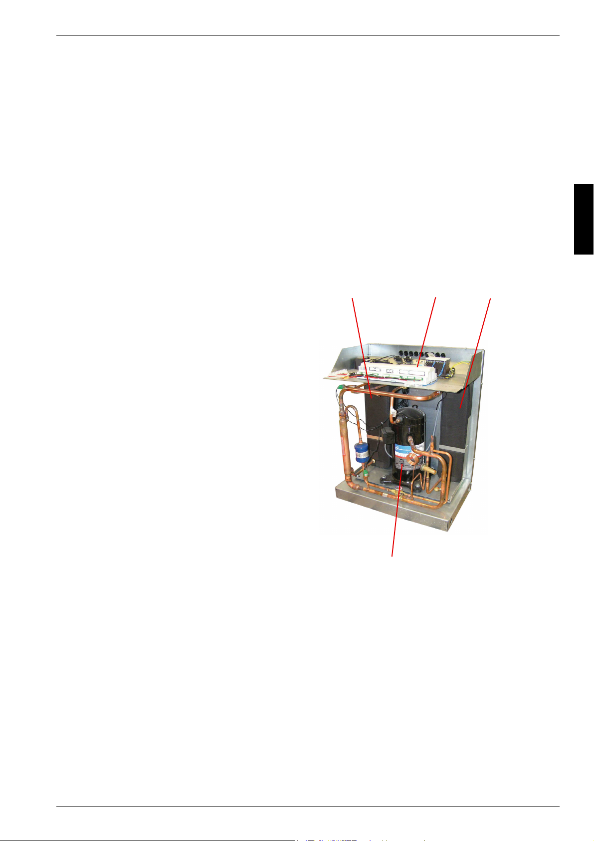
Für die Auftragsbearbeitung werden die Erzeugnisnummer E-Nr.
und das Fertigungsdatum FD des Gerätes benötigt. Diese Anga-
ben befinden sich auf dem Typschild in dem stark umrandeten
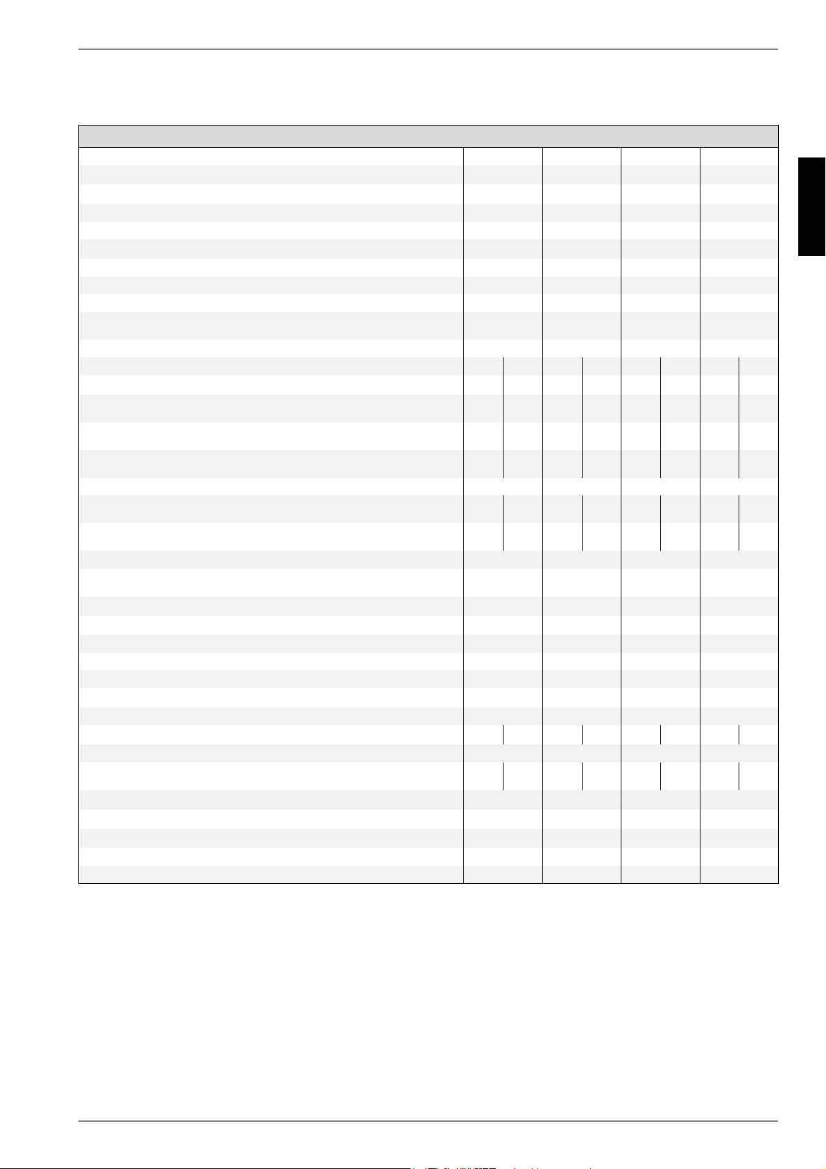
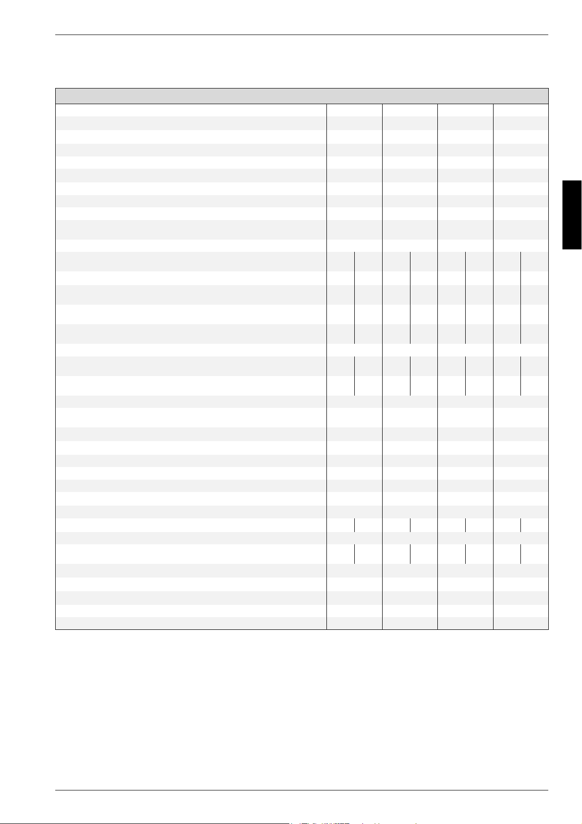
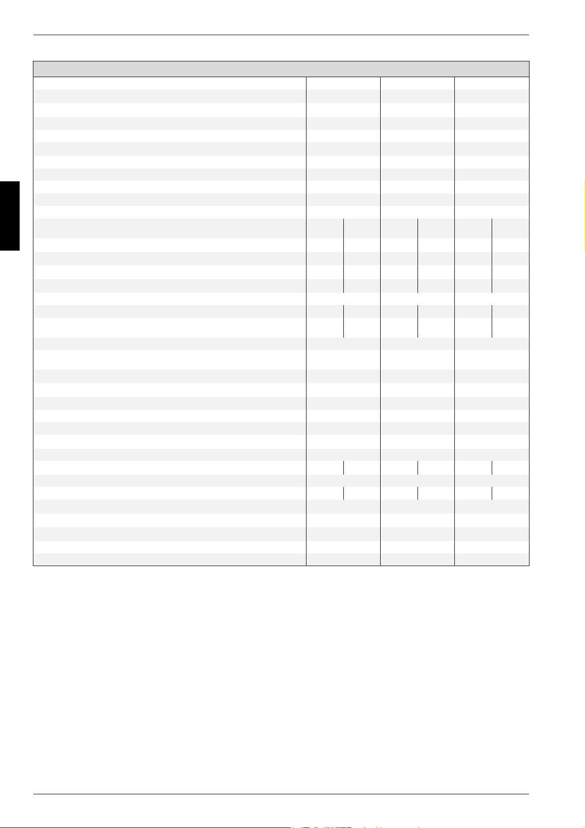
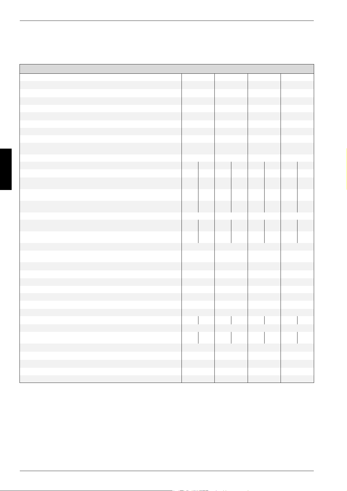
Heating water flow°CUp to 58Up to 58Up to 58Up to 58
Brine (heat source)°C-5 to +25-5 to +25-5 to +25-5 to +25
AntifreezeMono-ethylene
glycol
Mono-ethylene
glycol
Mono-ethylene
glycol
Mono-ethylene
glycol
Minimum brine concentration (-13 °C freezing temperature)25%25%25%25%
3.2Temperature spread of heating water (flow/return flow)
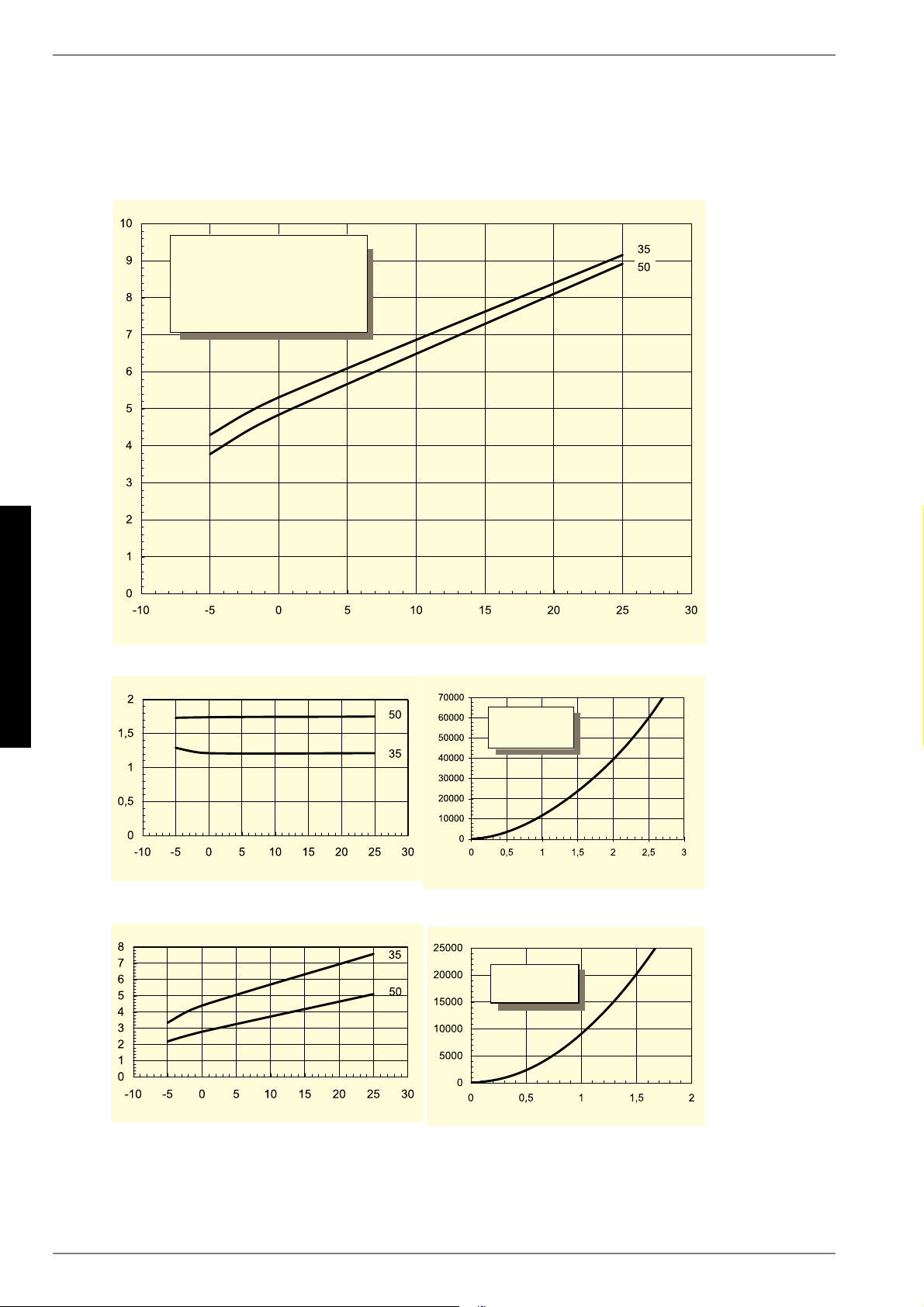
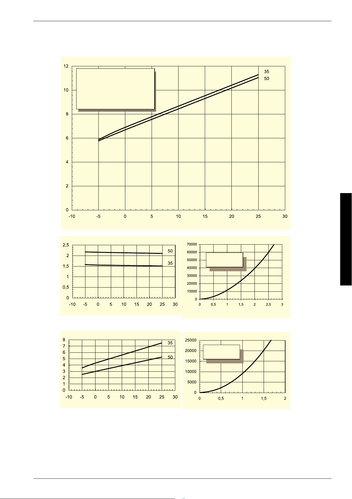
at B0 / W35K10.15.09.95.010.55.010.15.0
3.3Heat output / COPat B-5 / W55 1kW / ---
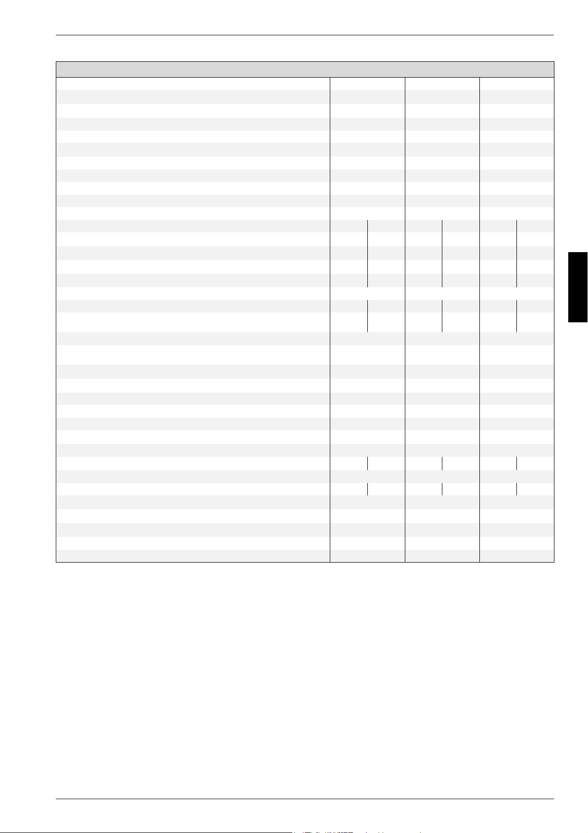
1.This data indicates the size and capacity of the system. For an analysis of the economic and energy efficiency of the system, both the bivalence point and the regulation should
also be taken into consideration. The specified values, e.g. B10/ W55, have the following meaning: Heat source temperature 10°C and heating water flow temperature 55°C.
2.Note that additional space is required for pipe connections, operation and maintenance.
3.See CE declaration of conformity
4.The heat circulating pump and the heat pump manager must always be ready for operation.
1.Ces indications caractérisent la taille et le rendement de l’installation. Le point de bivalence et la régulation sont à prendre en compte pour des considérations économiques et
énergétiques. Ici, B10/W55 signifie par ex. : température extérieure 10°C et température départ eau de chauffage 55°C.
1.Ces indications caractérisent la taille et le rendement de l’installation. Le point de bivalence et la régulation sont à prendre en compte pour des considérations économiques et
énergétiques. Ici, B10/W55 signifie par ex. : température extérieure 10°C et température départ eau de chauffage 55°C.
2.Tenir compte de la place nécessaire plus importante pour le raccordement des tuyaux, la commande et l’entretien.
3.Voir déclaration de conformité CE
4.Le circulateur de chauffage et le régulateur de la pompe à chaleur doivent toujours être prêts à fonctionner.
Gebruikershandleiding.com neemt misbruik van zijn services uitermate serieus. U kunt hieronder aangeven waarom deze vraag ongepast is. Wij controleren de vraag en zonodig wordt deze verwijderd.
Product:
Spelregels forum
Om tot zinvolle vragen te komen hanteren wij de volgende spelregels:
lees eerst de handleiding door;
controleer of uw vraag al eerder door iemand anders is gesteld;
probeer uw vraag zo duidelijk mogelijk te stellen;
heeft u een probleem en al geprobeerd om dit op te lossen, vermeld dit erbij aub;
heeft u een oplossing gekregen van een bezoeker dan horen wij dat graag in dit forum;
wilt u een reactie geven op een vraag of antwoord, gebruik dan niet dit formulier maar klik op de knop 'reageer op deze vraag';
uw vraag wordt direct op de website gezet; vermijd daarom persoonlijke gegevens in te vullen;
Belangrijk! Als er een antwoord wordt gegeven op uw vraag, dan is het voor de gever van het antwoord nuttig om te weten als u er wel (of niet) mee geholpen bent! Wij vragen u dus ook te reageren op een antwoord.
Belangrijk! Antwoorden worden ook per e-mail naar abonnees gestuurd. Laat uw emailadres achter op deze site, zodat u op de hoogte blijft. U krijgt dan ook andere vragen en antwoorden te zien.
Abonneren
Abonneer u voor het ontvangen van emails voor uw Dimplex SI 14TE bij:
nieuwe vragen en antwoorden
nieuwe handleidingen
U ontvangt een email met instructies om u voor één of beide opties in te schrijven.
Ontvang uw handleiding per email
Vul uw emailadres in en ontvang de handleiding van Dimplex SI 14TE in de taal/talen: Duits, Engels, Frans als bijlage per email.
De handleiding is 5.86 mb groot.
U ontvangt de handleiding per email binnen enkele minuten. Als u geen email heeft ontvangen, dan heeft u waarschijnlijk een verkeerd emailadres ingevuld of is uw mailbox te vol. Daarnaast kan het zijn dat uw internetprovider een maximum heeft aan de grootte per email. Omdat hier een handleiding wordt meegestuurd, kan het voorkomen dat de email groter is dan toegestaan bij uw provider.
Uw handleiding is per email verstuurd. Controleer uw email
Als u niet binnen een kwartier uw email met handleiding ontvangen heeft, kan het zijn dat u een verkeerd emailadres heeft ingevuld of dat uw emailprovider een maximum grootte per email heeft ingesteld die kleiner is dan de grootte van de handleiding.
Er is een email naar u verstuurd om uw inschrijving definitief te maken.
Controleer uw email en volg de aanwijzingen op om uw inschrijving definitief te maken
U heeft geen emailadres opgegeven
Als u de handleiding per email wilt ontvangen, vul dan een geldig emailadres in.
Uw vraag is op deze pagina toegevoegd
Wilt u een email ontvangen bij een antwoord en/of nieuwe vragen? Vul dan hier uw emailadres in.