Fastening the mounting sheet (fig. 3)
Caution:Level the mounting sheet,make sure that the inlet
pipe goes down towards the outside.(1 cm to 1 m) and
that the wall grid lies straight against the exterior wall.
Then,any condensation will never get into the heater
because of the downwards flow of the pipe.
• Now tighten the screw nuts on the tension members
• Saw or cut the tension members so that they do not stick
out from the fastening clamps (5).
• Drill the hole for the key bolt (7).
• Attach the key bolt and attach the mounting sheet using
the bolt (8) and washer (9).
Installation to a wall of inflammable material
(fig. 2)
When the appliance is installed to a wall of flammable
material,the wall duct should be executed as follows.
• On the spot of the duct,create a square opening in the
wall ( 280 mm).
• In the case of compressible walls,fill up the space all
round the opening well,so that the wall cannot be
crushed.
• In addition,replace the bolt (8) (fig 3) by e.g.a wood
screwed bolt.
• On the room side,put the heat shield (14) between the
mounting sheet (2) and the wall.
• On the outside of the wall,using 4 screws (16),attach
siluminplate (15).
The heat shield (14) and the silumin plate (15) are packed
together and are available from your dealer.Assembling the
wall duct is otherwise the same as previously described.
N.B. To calculate the length of the inlet and outlet pipe,
the thickness of siluminplate (15) should be included.
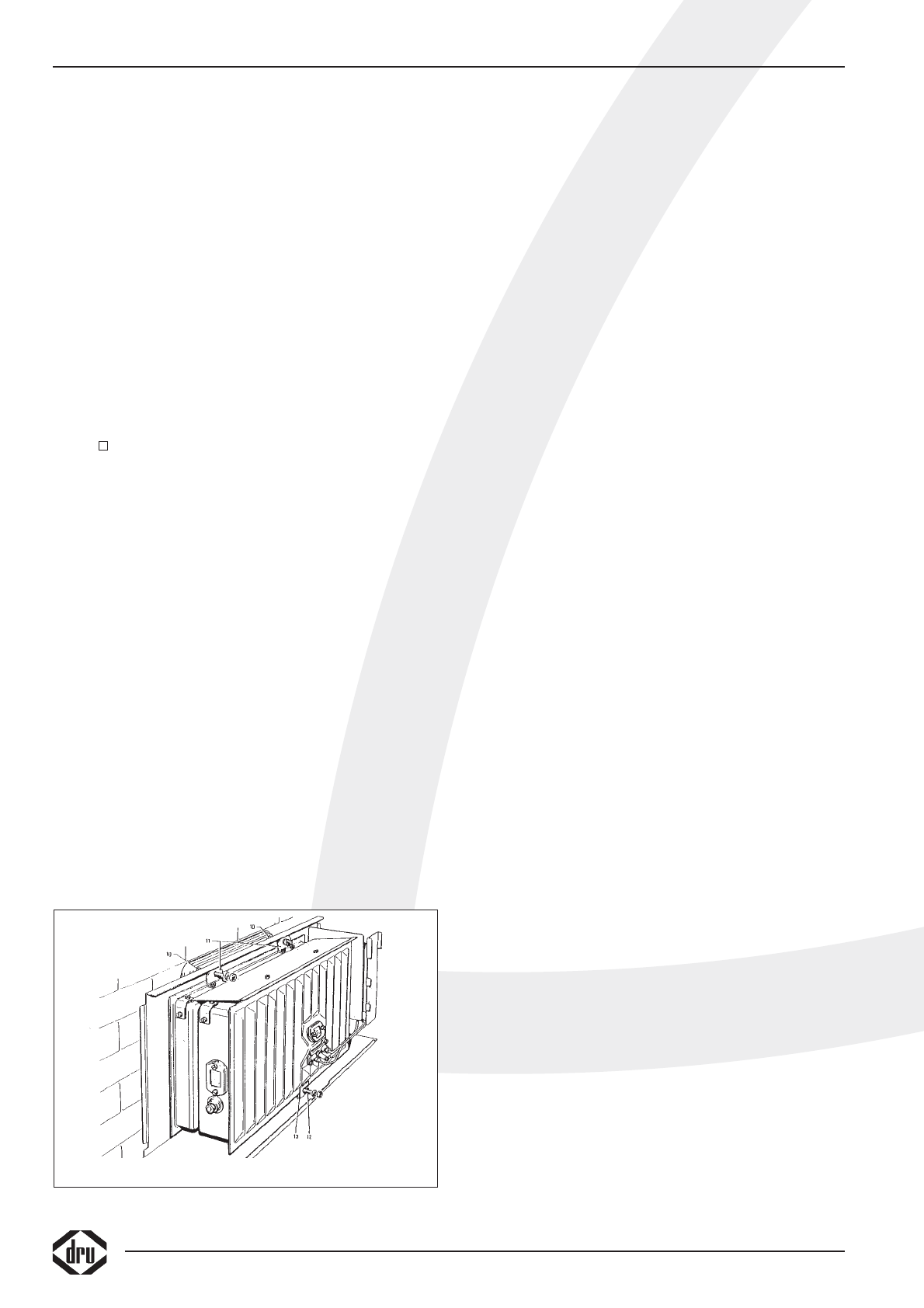
Installation of the interior (fig.4)
Slide the adjusted outlet pipe into the gird opening.Slide
the two Silicon Rubber Tulles (packed with the glass silk
rope) over the bolts (10) and into the holes of the back
plate.
This prevents possible dirt and deposit from settling onto
the wall.Take the interior and put it with the bottom edge
on the two supports of the mounting sheet.Keep the inte-
rior balanced and slide the outlet pipe a little bit into the
outlet opening of the interior for support.Now slide the
interior against the mounting sheet,taking care that the
turned-back edge of the mounting sheet fits into the inlet
bush on the back side of the interior and that the bolts
(10) stick through the clamps (11).Attach screw nuts and
washers to the bolts (10) and tighten closely up to the
stop.Then slide the screw spindle (12) into the clamp (13).
Fix the screw nut and washer to the screw spindle (12)
and tighten until the interior is standing parallel to the wall.
N.B. If easy accessible,e.g.on the ground floor,the outlet
pipe can also be mounted from the outside after the grid
interior sheet and the basket have been disassembled.
Connection of the gas supply
The connection has a 3/8" BSP inside thread.If the supply
pipe enters the appliance through the back plate,press out
the disc in the plate. An approved connecting tap with
coupling should be used in the supply pipe (For Belgium
this should be B.G.V.approved).The connecting tap with
coupling should be fitted outside the casing. Furthermore:
• Expel all air from the supply pipes/hoses before coupling
to the appliance.
• Do not turn the coupling tap when connecting it to the
gas supply.
• Avoid any pressure on the control tap and pipes.
• Check that all connections are gastight.
Operations
The manufacturer has made the appliance suitable for the
type of gas as indicated on the type identification tag.The
thermostat regulates modulatingly between "full power
setting" and "low power setting" and ,when little heat is
required,in two settings,i.e."low" or "off".In this situation,
the pilot light keeps burning.The "low" setting can only be
checked when the room temperature is higher than ±
15°C (60°F).
The low setting
The low setting has been adjusted to ± 20% of the full
consumption.The low setting screw has been fully tight-
ened and is supplied with the correct low setting bore.
This is not adjustable.
Pilot light burner
Upon delivery,the pilot light burner has the correct con-
sumption by means of a nozzle inside the pilot light burn-
er.The pilot light burner needs no adjustment.
Placing the housing
Hang the top of the casing over the back plate (the sides
of the casing remain in front of the back plate) and ensure
that the control buttons drop into the appropriate recess
in the casing.
Important
A built-in safety lock is activated when the appliance is
switched to "OFF" (closed down setting).Therefore,wait
5 minutes before relighting the heater.Within this period,
do not try to push the lighting button,as this has been
blocked by the safety lock.Do not force the button,as this
may result in damage to the mechanism.
12
INSTRUCTIONS FOR INSTALLATION
fig.4