SETTING
7-6
CC
CAUTION:
If a change in conditions require a main jet
of a larger size, use the size to which #20 is
added for safety.
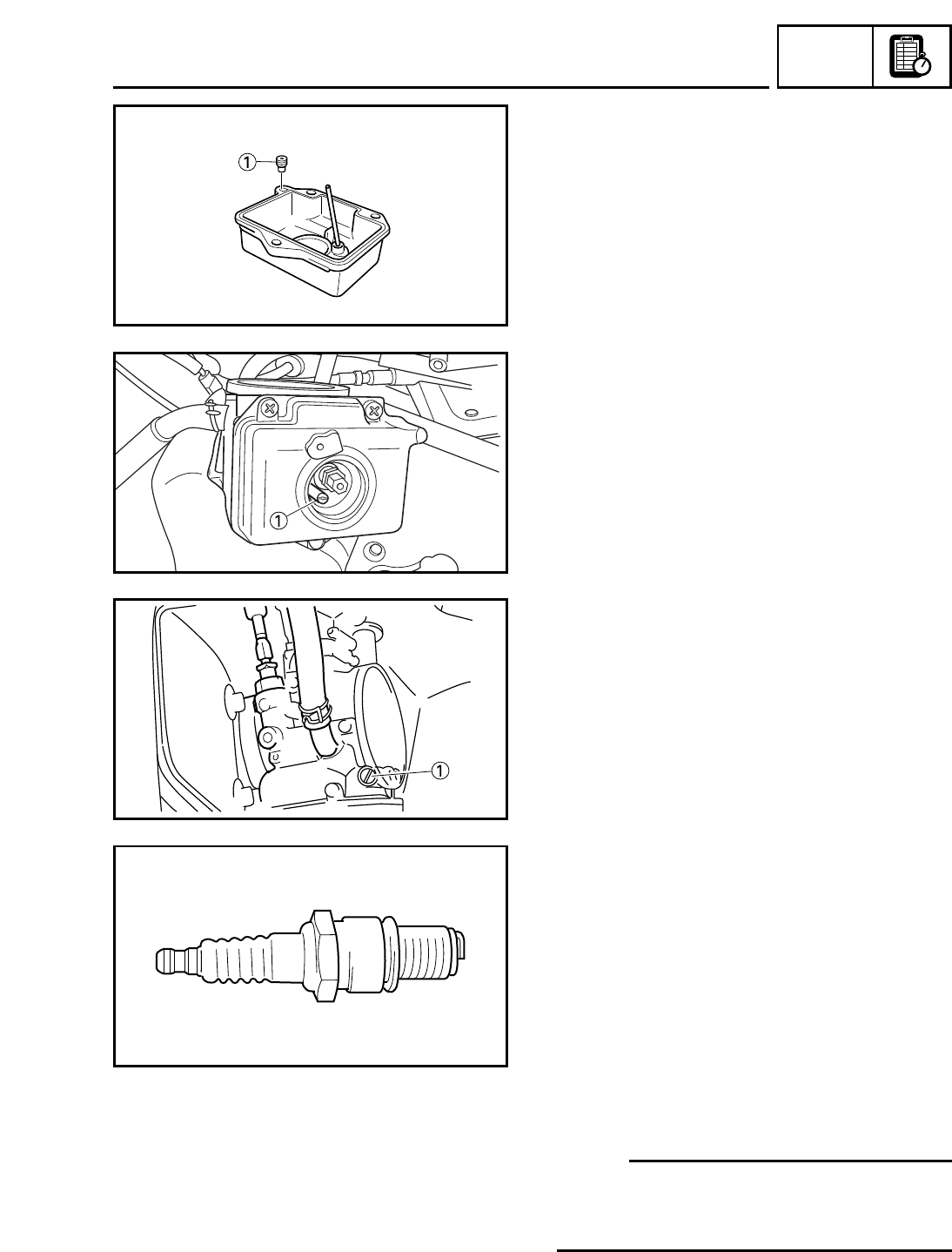
NOTE:
• Since this correction coefficient table lacks a
column for humidity, it is advisable to check
the degree of discoloration of the spark
plug(s) for final selection according to an
explanation under “Atmospheric conditions
and carburetor setting’’ (P7-1).
• As the main nozzle is more susceptible to
other than atmospheric conditions, no correc-
tion coefficient is used for main nozzle set-
ting.
TUN
EC71G002
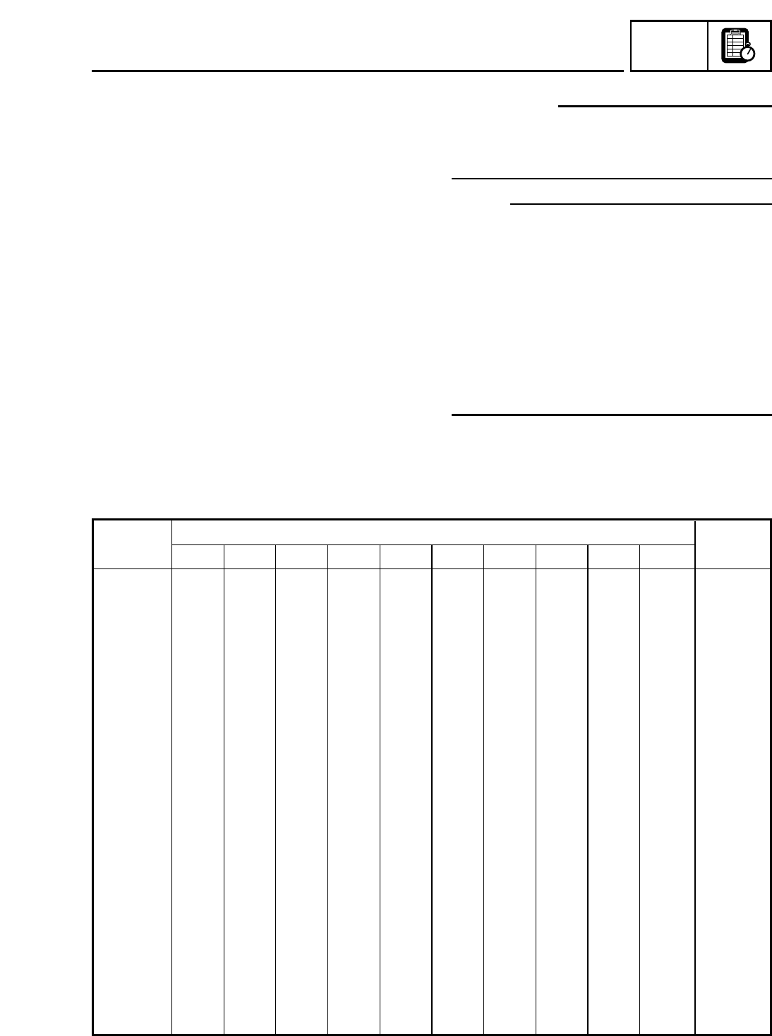
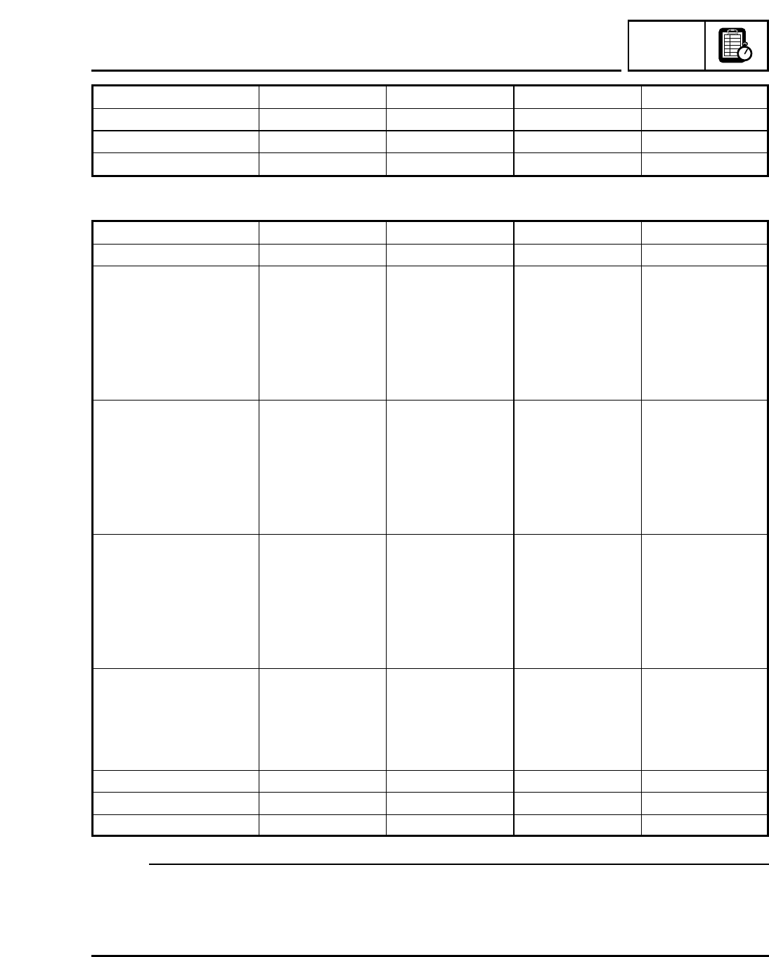
Table of correction coefficients for carburetor setting
Air
pressure
Air temperature °C (°F)
Altitude
hPa (mmHg)
-5 (23) Zero (32) 5 (41) 10 (50) 15 (59) 20 (68) 25 (77) 30 (86) 35 (95) 40(104)
m (ft)
1040 (780) 112.2 110.2 108.2 106.3 104.4 102.6 100.9 99.3 97.7 96.1 -220 (-722)
1033 (775) 111.5 109.4 107.5 105.6 103.7 102.0 100.3 98.6 97.0 95.5 -165 (-541)
1027 (770) 110.8 108.7 106.8 104.9 103.1 101.3 99.6 98.0 96.4 94.8 -110 (-361)
1020 (765) 110.0 108.0 106.1 104.2 102.4 100.7 99.0 97.3 95.8 94.2 -55 (-180)
1013 (760) 109.3 107.3 105.4 103.5 101.7 100.0 98.3 96.7 95.1 93.6 Zero (Zero)
1007 (755) 108.6 106.6 104.7 102.9 101.1 99.3 97.7 96.1 94.5 93.0 56 (184)
1000 (750) 107.9 105.9 104.0 102.2 100.4 98.7 97.0 95.4 93.9 92.4 112 (367)
993 (745) 107.2 105.2 103.3 101.5 99.7 98.0 96.4 94.8 93.3 91.8 168 (551)
987 (740) 106.5 104.5 102.6 100.8 99.1 97.4 95.7 94.2 92.6 91.1 224 (735)
980 (735) 105.7 103.8 101.9 100.1 98.4 96.7 95.1 93.5 92.0 90.5 281 (922)
973 (730) 105.0 103.1 101.2 99.4 97.7 96.1 94.4 92.9 91.4 89.9 338 (1,109)
967 (725) 104.3 102.4 100.5 98.8 97.1 95.4 93.8 92.2 90.7 89.3 396 (1,299)
960 (720) 103.6 101.7 99.8 98.1 96.4 94.7 93.1 91.6 90.1 88.7 453 (1,486)
953 (715) 102.9 101.0 99.2 97.4 95.7 94.1 92.5 91.0 89.5 88.1 512 (1,680)
947 (710) 102.1 100.3 98.5 96.7 95.0 93.4 91.9 90.3 88.9 87.5 570 (1,870)
940 (705) 101.4 99.6 97.8 96.0 94.4 92.8 91.2 89.7 88.2 86.8 629 (2,064)
933 (700) 100.7 98.9 97.1 95.4 93.7 92.1 90.6 89.1 87.6 86.2 688 (2,257)
927 (695) 100.0 98.1 96.4 94.7 93.0 91.4 89.9 88.4 87.0 85.6 747 (2,451)
920 (690) 99.3 97.4 95.7 94.0 92.4 90.8 89.3 87.8 86.4 85.0 807 (2,648)
913 (685) 98.5 96.7 95.0 93.3 91.7 90.1 88.6 87.2 85.7 84.4 867 (2,845)
907 (680) 97.8 96.0 94.3 92.6 91.0 89.5 88.0 86.5 85.1 83.8 928 (3,045)
900 (675) 97.1 95.3 93.6 92.0 90.4 88.8 87.3 85.9 84.5 83.1 989 (3,245)
893 (670) 96.4 94.6 92.9 91.3 89.7 88.2 86.7 85.2 83.9 82.5 1,050 (3,445)
887 (665) 95.7 93.9 92.2 90.6 89.0 87.5 86.0 84.6 83.2 81.9 1,111 (3,645)
880 (660) 94.9 93.2 91.5 89.9 88.3 86.8 85.4 84.0 82.6 81.3 1,173 (3,848)
873 (655) 94.2 92.5 90.8 89.2 87.7 86.2 84.7 83.2 82.0 80.7 1,236 (4,055)
867 (650) 93.5 91.8 90.1 88.5 87.0 85.5 84.1 82.7 81.4 80.1 1,299 (4,262)
860 (645) 92.8 91.1 89.4 87.9 86.3 84.9 83.4 82.1 80.7 79.4 1,362 (4,469)
853 (640) 92.1 90.4 88.8 87.2 85.7 84.2 82.8 81.4 80.1 78.8 1,425 (4,675)
847 (635) 91.3 89.7 88.1 86.5 85.0 83.6 82.2 80.8 79.5 78.2 1,489 (4,885)
840 (630) 90.6 89.0 87.4 85.8 84.3 82.9 81.5 80.2 78.9 77.6 1,554 (5,099)