When you select a different style while the accompaniment
is not playing, the “default” tempo for that style is also selected,
and the tempo is displayed on the display in beats per minute.
If the accompaniment is playing, the same tempo is maintained
even if you select a different style.
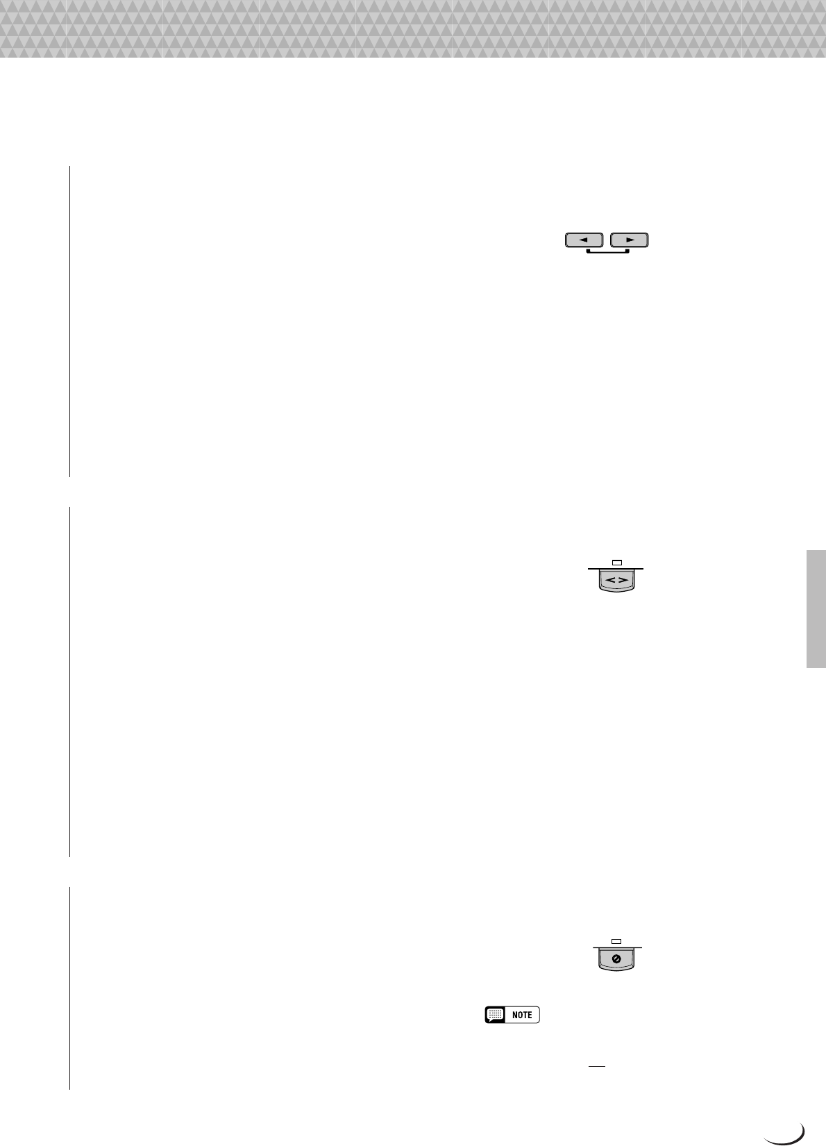
You can change the tempo to any value between 32 and 280
beats per minute, however, by using the TEMPO [<] and [>]
buttons. This can be done either before the accompaniment is
started or while it is playing. To use the [<] and [>] buttons,
press either button briefly to decrement or increment the tempo
value by one, or hold the button for continuous decrementing or
incrementing.
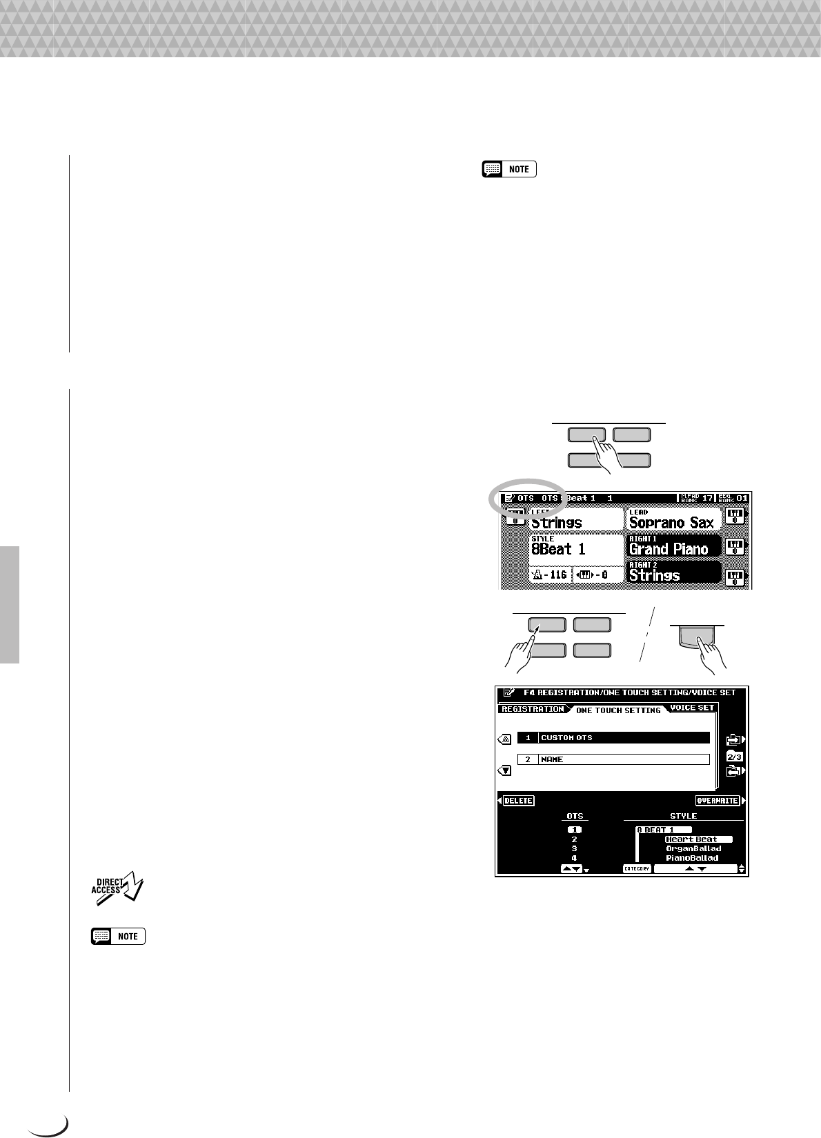
The default tempo for the selected style can be recalled at
any time by pressing both the TEMPO [<] and [>] buttons
simultaneously.
■Fade-ins and Fade-outs.......................................................................................................................................................
The [FADE IN/OUT] button can be used to produce smooth
fade-ins and fade-outs when starting and stopping the accompa-
niment.
To produce a fade-in, press the [FADE IN/OUT] button so
that its indicator lights before starting the accompaniment (the
fade-in can be cancelled by pressing the button a second time).
Then when the accompaniment is started the sound will gradu-
ally fade in. The [FADE IN/OUT] indicator will flash during
the fade-in, and then go out when full volume has been reached.
To produce a fade-out press the [FADE IN/OUT] button
while the accompaniment is playing. The indicator will flash
during the fade out, then the accompaniment will stop when the
fade-out is complete. The [FADE IN/OUT] button indicator
will remain lit for a few seconds after the fade-out, indicating
that the fade-in mode is engaged. Press the [FADE IN/OUT]
button so that its indicator goes out if you want to disengage the
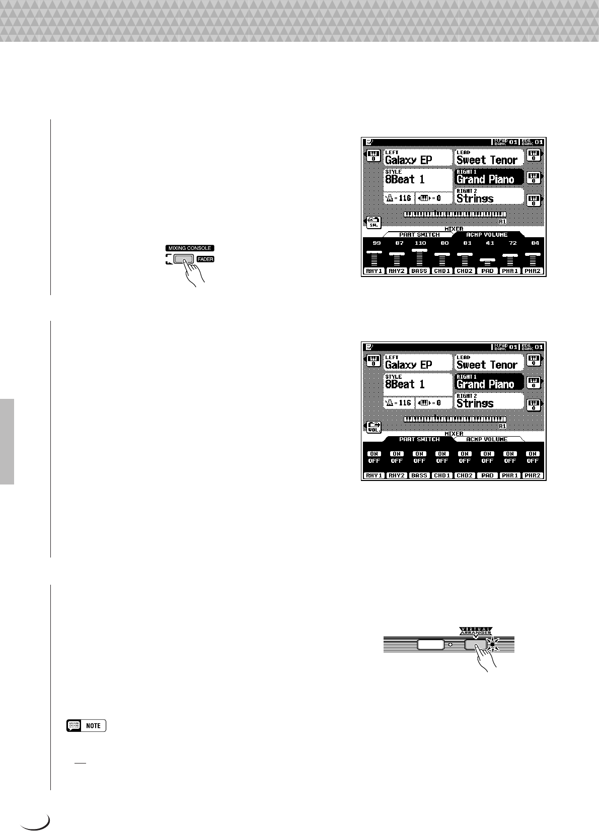
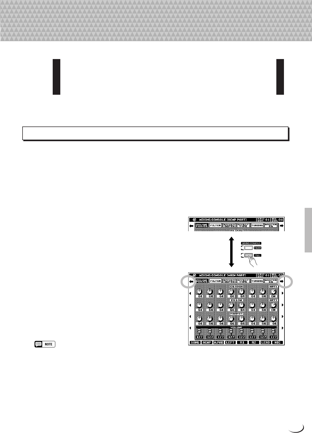
Use the various LCD dials in the MIXING CONSOLE [FADER]
ACMP VOLUME display to set the best balance between the
corresponding accompaniment parts. The MAIN VOLUME
and ACMP VOLUME displays can be used to set the balance
between the keyboard and accompaniment sound (use the
[FADER] button to toggle between the MAIN VOLUME and
ACMP VOLUME displays).
■Accompaniment Part Switching.................................................................................................................................
The PART SWITCH buttons accessible via the MIXING
CONSOLE [FADER] ACMP VOLUME display make it pos-
sible to individually mute accompaniment parts to create the
blend and accompaniment “size” you want. With the MIXING
CONSOLE [FADER] ACMP VOLUME display showing,
press the LCD “SW.” button to bring the PART SWITCH
display to the front.
Use the LCD dials to turn the corresponding accompaniment
parts ON or OFF, as required.
The PART SWITCH display accessed from the MIXING
CONSOLE [FADER]MAIN VOLUME display additionally
includes an ACMP parameter with LARGE and SMALL set-
tings (use the [FADER] button to toggle between the ACMP
and MAIN displays). These select different arrangement “sizes”
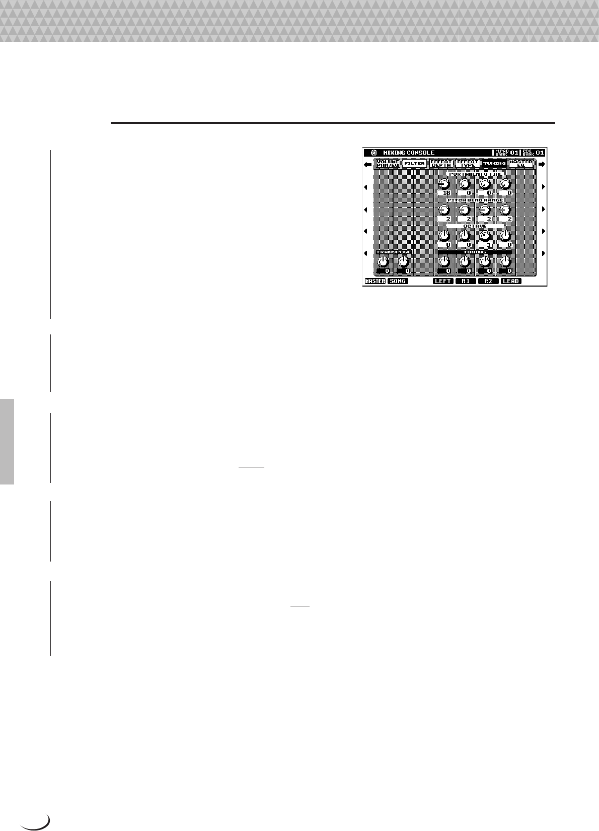
These OCTAVE parameters are separate from the octave parameters accessed via the normal play mode display (page
27), and have a –2 … +2 range as opposed to the –1 … +1 range of the play-mode octave parameters. The values
of the mixer’s OCTAVE parameters are
added to those of the corresponding play-mode octave parameters.
■PITCH BEND RANGE..............................................................................................................................................................
Set the range of the PITCH BEND wheel for the corresponding part. The range is from “0” to “12” with each step
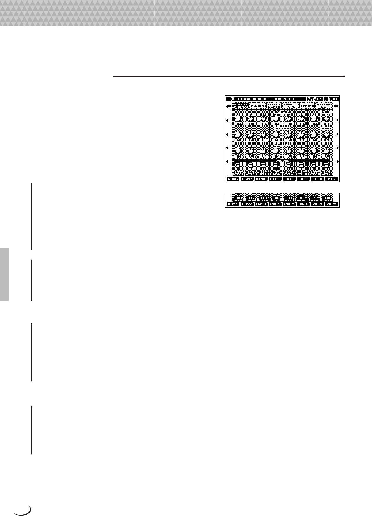
Whenever an EQ band is edited the corresponding EQ value is highlighted and the number of the edited band appears
above the Q and FREQ controls. The Q and FREQ controls can then be used to adjust the Q (bandwidth) and center
frequency of the selected band. The higher the “Q”, the narrower the bandwidth. The available FREQ range is
different for each band.
■TOTAL GAIN ADJUST.............................................................................................................................................................
This dial adjusts the overall gain of all EQ bands simultaneously.
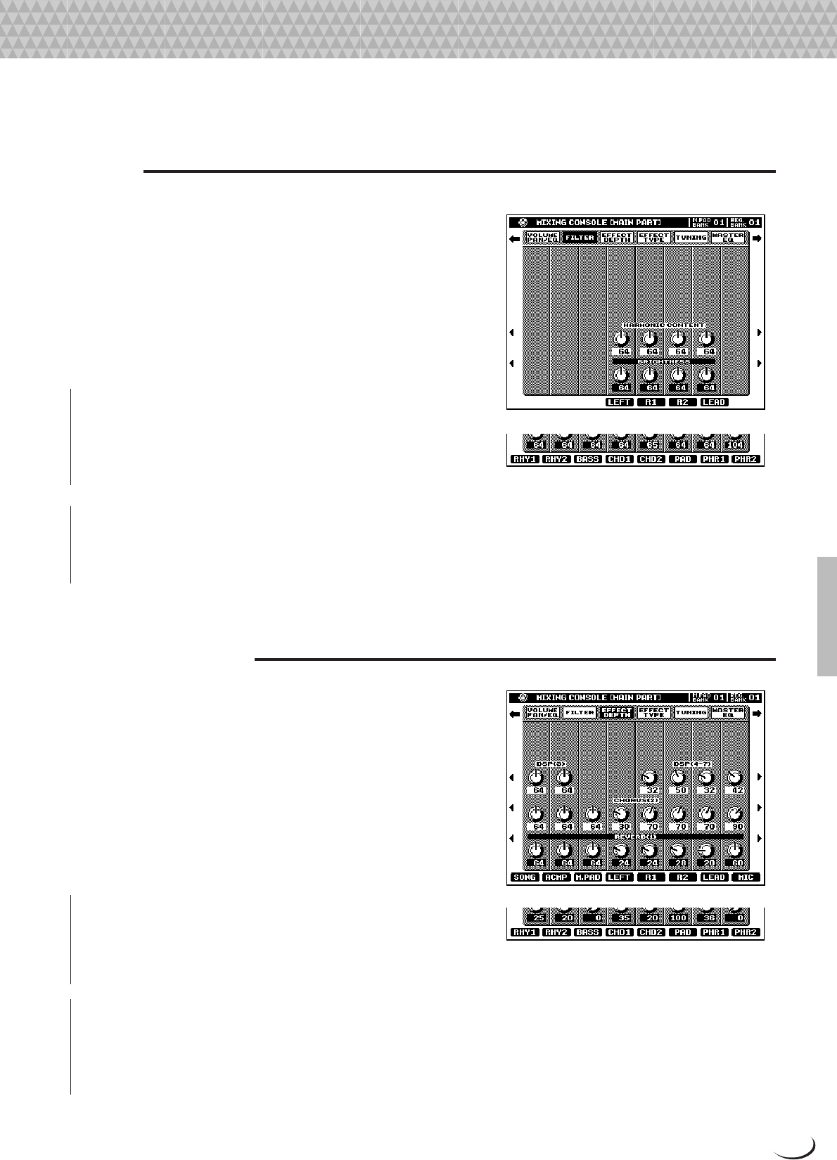
The same parameters as for MODULATION, above, but ap-
plied via keyboard after-touch response.
Custom Voice Creator
56
Custom Voice Creator
E1:WAVEFORM
■WAVEFORM (INSTRUMENT for the Drum Kits)...............................................................................................................
Use the CATEGORY, VOICE, and WAVEFORM LCD dials
to select a waveform for the custom voice: the raw sound on
which the voice is based. Waveforms created by the SAM-
PLING feature (page 88) are also available for selection in the
“SAMPLING” CATEGORY. When a waveform which has EG
data is selected, the EG COPY LCD button will become avail-
able, and pressing it will cause the corresponding EG data to be
loaded.
When a Drum Kit is selected the WAVEFORM parameter is
replaced by the INSTRUMENT parameter, and individual
instruments can be selected rather than waveforms.
The PAN LCD dial can be used to position the voice in the
center of the stereo sound field, or to the left or right.
■NOTE LIMIT (not available for the Drum Kits) ..................................................................................................................
Specifies the note range over which the voice will sound. The
LOW dials set the lowest note in the range and the HIGH dials
set the highest note in the range.
•When the voice OCTAVE is set to a value other than “0”, the range
specified by the NOTE LIMIT parameters is shifted by the correspond-
ing amount and some notes may not sound. If this happens check the
R1 OCTAVE setting in the FULL MIXING CONSOLE TUNING display.
■VELOCITY LIMIT (not available for the Drum Kits).
Sets the maximum velocity range for the voice. The LOW dials
set the minumum velocity value and the HIGH dials set the
maximum velocity value at which the voice will sound. No
sound is produced for velocity values outside the specified
These parameters set the rate of pitch variation. Higher values
produce faster variation.
DECAY1,Set the rate of variation between the initial pitch
envelope level and the levels set by the PITCH
LEVEL DECAY1, DECAY2, and DECAY3 param-
eters, respectively.
RELEASESets the rate of variation from the level at key-
release to the level set by the PITCH LEVEL
RELEASE parameter.
DECAY2,
DECAY3
87
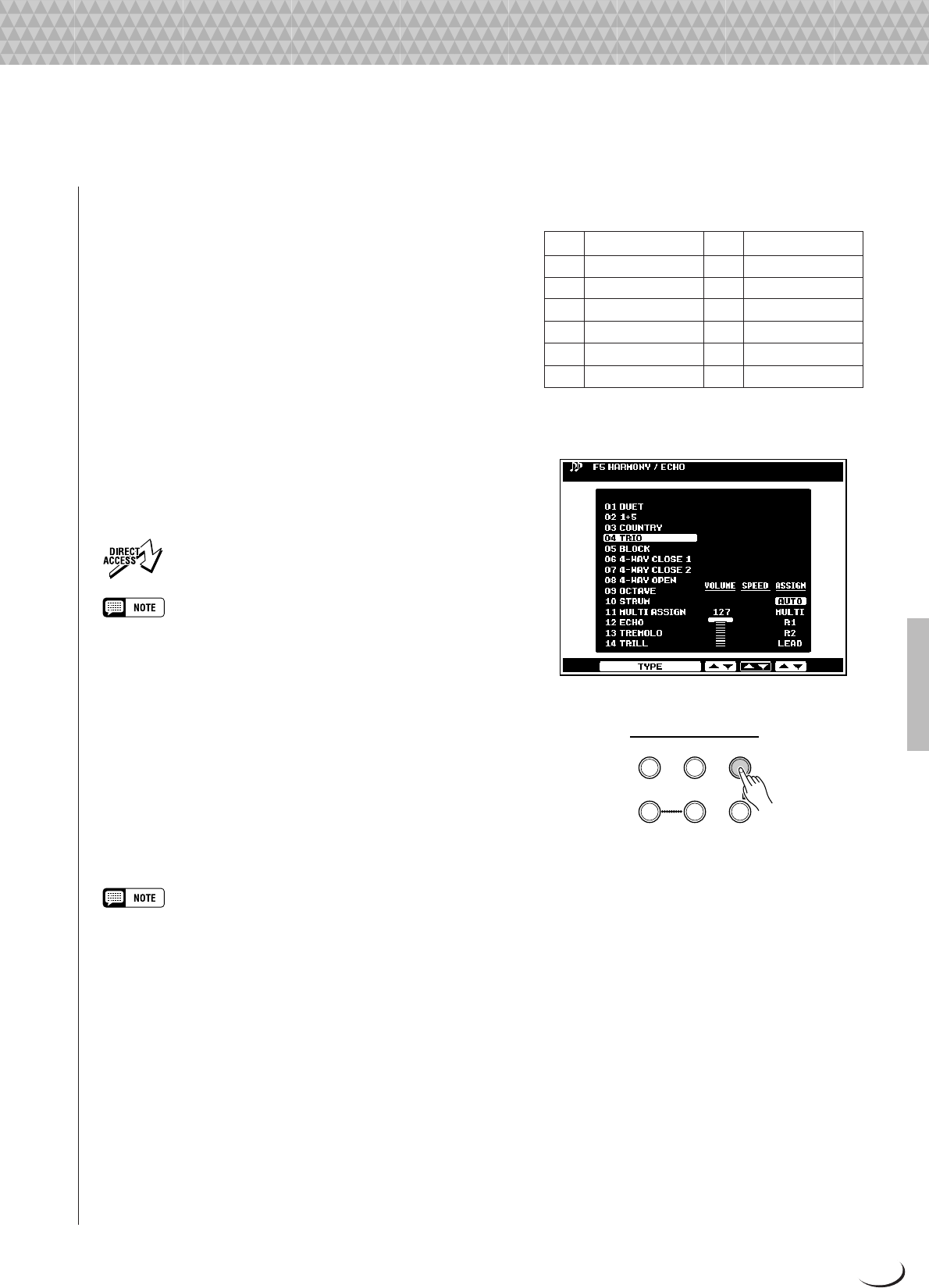
“DetuneType” Parameter Settings
Type NameLCDHarmony 1Harmony 2
abbrevi-Pitch ShiftPitch Shift
ation
(none when
Lead Gender on)
TrioLowTrioLo–7 cents+7 cents
TrioMid-LowTrioML–11 cents+11 cents
TrioMid-HighTrioMH–15 cents+15 cents
TrioHighTrioHi–20 cents+20 cents
DuetLowDuetLo–7 cents- -
DuetMid-LowDuetML–11 cents- -
DuetMid-HighDuetMH–15 cents- -
DuetHighDuetHi–20 cents- -
● Detune
Detune Types add vocal notes which are detuned by a specific
amount, thus adding a chorus effect to the lead voice.
● Chromatic
In this mode the harmony notes are always produced at the
specified interval from the lead vocal.
“ChromaticType” Parameter Settings
Type NameLCDHarmony 1Harmony 2
abbrevi-PitchPitch
ation
(none when
Lead Gender on)
OctaveBelowOctBlw1 octave down- -
3rdBelow3rdBlwMinor 6th down- -
5thBelow5thBlw
Perfect 4th down
- -
UnisonUnisonUnison- -
3rdAbove3rdAbvMajor 3rd up- -
5thAbove5thAbvPerfect 5th up- -
OctaveAboveOctAbv1 octave up- -
GregorianIGregI1 octave downPerfect 4th down
GregorianIIGregII1 octave downPerfect 4th up
Unison+OctaveAboveUnsnOAUnison1 octave up
Unison+OctaveBelowUnsnOB1 octave downUnison
Vocal Harmony
•Received MIDI note data can also be used to specify the Vocoder mode harmony notes when the MIDI receive mode is set to “VOCAL
HARMONY” (page 136). The volume, pan, detune, modulation, and pitch bend of any Vocal Harmony type can be adjusted via
control change or pitch bend data.
•The Vocal Harmony song track and the Vocal Harmony MIDI channel, described above, are always linked: e.g. if the song track is
changed to 3, MIDI receive channel 3 will automatically be set to the VOCAL HARMONY mode, and vice versa.
•With a Vocoder mode type it is possible to produce an “a capella” vocal chorus effect by turning the volume of the panel voices all
the way down.
88
Sampling
Sampling
The PSR-8000 SAMPLING feature lets you “sample” sounds via a microphone or
line source which can be saved as “waves” within “waveforms” to be used in
original custom voices (see “PSR-8000 Waves & Waveforms”, below). The SAM-
PLING mode also includes a range of wave and waveform editing features which
can be used to “fine tune” your samples for optimum sound.
During use sampled sounds are kept in the internal wave RAM memory. The
PSR-8000 comes with a 1-megabyte wave memory which can be expanded up
to a maximum of 33 megabytes by installing optional SIMM memory modules —
see page 152 for details. Sampled waveforms can be saved to floppy or hard
disk. Wave files in standard WAV or AIFF format produced using other equipment
can also be used by the PSR-8000.
•The supplied audio CD includes sound sources for sampling.
•No MIDI or TO HOST transmission or reception occurs in the SAMPLING mode.
PSR-8000 Waves & Waveforms
The terms “wave” and “waveform” have distinct meanings in PSR-8000 sampling terminology, as follows:
● WAVE
A “wave” is the raw audio data created whenever you sample
a new sound or import a WAV or AIFF format wave file. The
PSR-8000 WAVE EDIT mode includes functions which allow
you to edit this basic data: e.g. resampling to change the
sampling frequency, trimming and looping, normalization for
maximum level and minimum noise, etc.
● WAVEFORM
All PSR-8000 waves are contained in a “waveform”, which
is basically a set of parameters which define the keyboard range
over which the wave or waves it contains will play. A waveform
can contain one or more waves, and waves can be shared by
more than one waveform. Waves in a waveform can be assigned
to different ranges of the keyboard, but they cannot be layered
(i.e. they will not sound simultaneously when a single key is
played). The PSR-8000 WAVEFORM EDIT mode lets you add
or delete waves from a waveform, and assign the waves to
different keyboard ranges.
•When you sample a new sound or import a WAV or AIFF format wave,
a new waveform which contains the new sampled or imported wave is
automatically created. The PSR-8000 saves your edited data as a
waveform file.
● WAVEFORMS & VOICES
Waveforms created by the PSR-8000 SAMPLING feature
can be used in voices in two different ways:
WAVE EDIT
Sampling
Sound
WAVAIFF
WAVEWAVEWAVE
WAVEFORM
WAVE1WAVE2WAVE3
WAVEFORM
CUSTOM VOICE
CREATOR
CUSTOM VOICE
1
2
2
89
Sampling
1.
You can save the waveform directly as a CUSTOM VOICE (via the WAVEFORM EDIT SAVE AS CUSTOM
VOICE function). The CUSTOM VOICE can then be edited via the CUSTOM VOICE CREATOR (page 51)
allowing you to layer waveforms with other waveforms as voice “elements”, and apply envelope generators,
filtering, modulation, and other voice parameters as required.
2.
You can select and use sampled waveforms within the CUSTOM VOICE CREATOR (page 56) with full editing
control.
Setting Up for Sampling
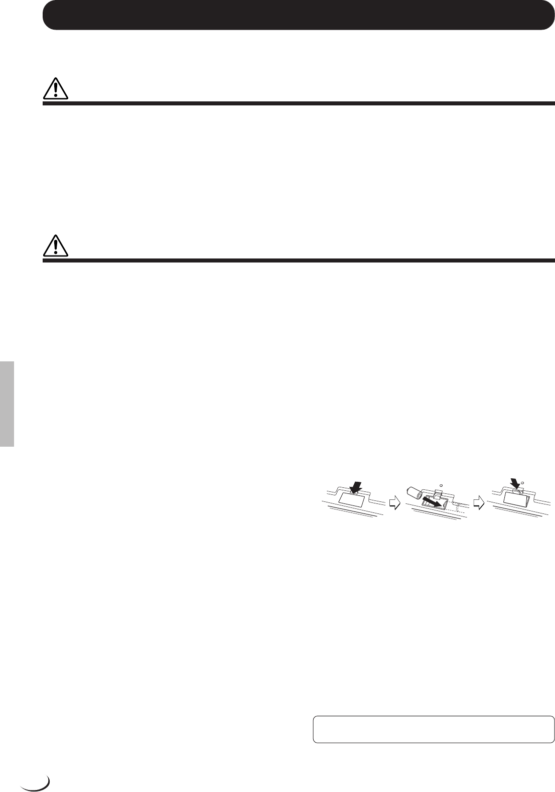
■Connecting the Source.........................................................................................................................................................
The first step in setting up for sampling is to connect your source
— microphone or line — to the PSR-8000.
If you will be using a microphone, set the panel MIC/LINE
selector to MIC, and plug your microphone into the MIC/
LINE IN jack. A standard dynamic microphone with an imped-
ance of about 250 ohms is recommended (the PSR-8000 does
not support phantom-powered condenser microphones).
If you will be sampling from a CD player or other line source
set the panel MIC/LINE selector to LINE. You may have to use
a stereo-to-mono cable or a “Y” cable to combine the left- and
right-channel output signals from the source device for input to
Enter an original name for the selected waveform as de-
scribed on page 21.
2: CLEAR
Clears the specified WAVEFORM or WAVE from memory.
Operation is the same as in the WAVE EDIT mode (page 96).
3: SAVE
This function saves the selected waveform to disk. Opera-
tion is the same as in the WAVE EDIT mode EXPORT AS WAV
function (page 96).
4: DELETE
Deletes unwanted wave or waveform files from disk. Opera-
tion is the same as in the WAVE EDIT mode (page 96).
Sampling
99
■STORE AS CUSTOM VOICE.............................................................................................................................................
1: CUSTOM VOICE NAME
Enter an original name for the custom voice as described on
page 21.
2: STORE AS CUSTOM VOICE
This function stores the current waveform as a custom voice
which can be edited via the CUSTOM VOICE CREATOR (page
51) or selected via the VOICE [CUSTOM VOICE] button and
played on the PSR-8000 keyboard in the same way as the other
voices.
Use the STORE AS CUSTOM VOICE LCD dials to select
the CUSTOM VOICE number to which you want to store the
waveform, then press the EXECUTE LCD button.
•The corresponding waveform must also be saved to disk in order to use
the stored custom voice the next time the PSR-8000 is turned on. If the
corresponding waveform has not been saved to disk, an alert will
appear following the SAVE AS CUSTOM VOICE operation.
•Waveform data is not actually stored with the CUSTOM VOICE data,
but is retained in the wave RAM memory. When the FUNCTION mode
AUTO LOAD function (page 131) is ON and a disk containing the
appropriate waveform data is loaded, the waveform data for the custom
voices will automatically be loaded into the wave RAM memory when
the PSR-8000 is turned on. If the AUTO LOAD function is off or the
appropriate waveform data is not found when the PSR-8000 is turned
on, the corresponding custom voices will automatically be erased.
•The VOICE SIZE shown on the display is the size of the custom voice
data (always 1K, not including the waveform data). The FREE AREA is
the total amount of remaining CUSTOM VOICE memory.
3: CLEAR CUSTOM VOICE
Use the CLEAR CUSTOM VOICE LCD dials to select a
CUSTOM VOICE to be cleared, then press the EXECUTE LCD
button.
Sampling
100
Song Playback
Song Playback
The PSR-8000 SONG mode allows song data to be played back from a floppy
disk or the optional hard disk. The song file types which can be played by the
PSR-8000 are: songs recorded on the PSR-8000, Yamaha DOC files, PianoSoft
type files and GM/XG/XF song (SMF formats 0 and 1) files.
Procedure: Song Playback
ZInsert a song disk.......................................................................................................................................................................
Insert a song disk into the PSR-8000 disk drive. This step can be
skipped if you will be playing a song from the optional internal
hard disk.
XEngage the song mode & select a song........
Press the [SONG] button to engage the SONG mode. The
[SONG] button indicator will light and a SONG name will
appear in place of the style name on the display. You can exit
from the SONG mode by pressing the [SONG] button again so
that its indicator goes out.
Press the [SONG SELECT] button to go to the song select
display if you want to select a different song. In fact, pressing
the [SONG SELECT] button automatically engages the SONG
mode if the [SONG] button has not been pressed, so you can
engage the SONG mode and go to the SONG SELECT display
in one step. You can return to the main SONG mode display by
pressing the [SONG] or [EXIT] button. If the optional hard
disk is present the DIRECTORY LCD dial in the SONG SE-
LECT display can be used to select the floppy disk or the hard
disk directory containing the desired song. Use the SONG
SELECT LCD dials to select the song you want to play.
● The Song Type Symbols
The symbol which appears between the song number and song
name indicates the song file type, as follows:
SONG
SONG SELECT
GGM (General MIDI)
UUser song
PPianoSoft type file
DDOC file
XXG or XF file
NNew song (only appears in the SONG SELECT display
when theSONG RECORD mode is engaged to select
a new song for recording)
/Other file type
101
Song Playback
CSelect a play mode....................................................................................................................................................................
Use the MODE LCD dials to select a play mode:
SINGLEPlays only the selected “CURRENT” song, or the “CURRENT” and “NEXT” songs if a “NEXT” song has
been entered (see below).
ALLPlays all songs in the SONG SELECT display song list in order, beginning with the currently selected
song. Also see “Enter Next Song”, below.
RANDOMPlays all songs in the SONG SELECT display song list in random order. Also see “Enter Next Song”,
below.
Also, use the REPEAT dial to turn the repeat mode ON or OFF as required. When ON, playback will repeat
EQ, FILTER, or EFFECT DEPTH display is selected, the
[FULL] button will select the normal parts display, song track
TR1—TR8, and song tracks TR9—TR16 in sequence. When
a song track display is selected “---” will appear in place of a
value for parameters which are not available.
Song Playback
•When a GM/XG song or a song with the “/” symbol in the SONG
SELECT display is played, all tracks appear on the display as if they
contain data, even if they don’t.
Muted trackPlay trackNo data
105
Song Recording
Song Recording
The PSR-8000 SONG RECORD mode allows anything you play to be recorded
to floppy or hard disk. A QUICK RECORD mode provides an easy way to record
a melody with accompaniment, while a MULTI TRACK record mode allows
independent recording on up to 16 tracks. There’s also a CHORD STEP record
mode available via the QUICK record mode.
•PSR-8000 songs are recorded using SMF format 0.
•Songs recorded using the XG category voices are XG compatible.
Procedure: Song Recording
ZInsert a recordable disk.......................................................................................................................................................
Insert a properly formatted disk in the PSR-8000 disk drive. This step is not necessary if you will be recording to
an internal hard disk (optional).
XEngage the song record mode................................
Press the [SONG/M. PAD RECORDING] button to engage
the SONG/MULTI PAD RECORD mode. The RECORDING
MENU display will appear. You can return to the normal play
mode by pressing the [SONG/M. PAD RECORDING] button
again, or by pressing the [EXIT] button.
CSelect a directory and/or song, if necessary................................................................................................
This step can be skipped if the desired directory/song is already
selected or you want to record a new song from scratch.
If you want to select a directory and/or add to an existing
song, press the [SONG SELECT] button to go to the SONG
SELECT display (described in the “Song Playback” section,
above) and select the desired directory and/or song. A DIREC-
TORY LCD dial will be available in the SONG SELECT display
only when the optional hard disk is present. It can be used to
select the floppy disk or the hard disk directory to which the
song is to be recorded.
Press the [EXIT] or [SONG/M.PAD RECORDING] but-
ton when done to return to the RECORDING MENU display.
VOICE
CREATOR
STYLE
CREATOR
FUNCTION
SONG/M.PAD
RECORDINGSAMPLINGDISK
OVERALL/UTILITY
SONG SELECT
109
Procedure: Chord Step Recording
The CHORD STEP recording feature makes it possible to record accompaniment chord changes one at a time
with precise timing. Since the changes don’t have to be entered in real time, it is easy to create even complex
accompaniments before recording the melody.
Select the CHORD STEP display via the or LCD button to the right of the display in the QUICK RECORD
mode.
ZSelect an entry point...............................................................................................................................................................
Use the CURSOR LCD dials to position the cursor at the
measure and beat at which you want to enter a chord or other
accompaniment event. The largest <> controls move the
cursor in 8-measure steps, the medium <> controls move the
cursor in 1-measure steps, while the small
<> controls position
the cursor in the smallest increment allowed for the current
style. Measure numbers appear above each measure division on
the “data line”, and the smaller division represent the smallest
increment available for the current style. The measure numbers
will scroll accordingly when the cursor is moved past the last or
first measure on the display (but not backwards past measure 1).
XSpecify a chord, volume change, or other event......................................................................................
To specify a chord change use the ROOT and TYPE LCD
dials to specify the chord. It is also possible to enter chords
directly via the AUTO ACCOMPANIMENT section of the
keyboard (but not when the FULL KEYBOARD or MANUAL
BASS fingering mode is selected).
To specify a volume change use the VOL. LCD dial to
specify the new volume level.
Other events which can be entered via the panel controls are:
STYLE changes, INTRO A/B, MAIN/AUTO FILL, ENDING
and TEMPO changes. STYLE change, INTRO A/B, and END-
ING events can only be entered at the top of each measure. The
edited event appears in inverse text in the event window near the
lower right corner of the display.
CEnter the specified event(s)........................................
Once the event or events to be entered have been specified as
described in the preceding step, press the SET LCD button to
actually enter the event at the current cursor position. A dot will
appear on the CHORD STEP data line and the cursor will
advance to the top of the next beat (or appropriate point).
Song Recording
110
VRepeat until done.......................................................................................................................................................................
Repeat steps 1 through 3, above, until the required number of chord changes and other accompaniment events
have been entered. The end of the sequence is automatically set at the end of an ENDING pattern, FADE OUT, one
measure after the last measure containing data, or the insert point of an END event (available at the bottom of the
When the cursor is located at any previously-entered dot on
the CHORD STEP data line, the type of event(s) recorded in that
location are indicated by triangular marker(s) to the left of the
corresponding event names in the event window. When only one
type of event has been entered at the cursor location an eraser
icon appears to the right of the corresponding event in the event
window, and that event can be erased simply by pressing the
DEL. LCD button. When more than one type of event has been
entered at the cursor location the SELECT LCD dial can be used
to place the eraser icon next to any of these events, and the
specified event can be erased by pressing the DEL. LCD button.
Events at the top of a measure can be changed but not deleted.
■INSERTING OR DELETING MEASURES.............................................................................................................
When the cursor is located at the first beat of a measure, a new
(blank) measure can be inserted at that location by pressing the
measure INS. LCD button to the left of the display.
An entire measure can be deleted by placing the cursor at the
first beat of the measure to be deleted, and then pressing the
measure DEL. LCD button to the left of the display.
■SAVING THE CHORD STEP DATA..............................................................................................................................
The entered CHORD STEP data is automatically saved to disk
when you switch displays, press the [EXIT] button, or press the
This function can be used to change the voices assigned to
any of the current song’s tracks.
Use the TRACK LCD dials to select the track to which a new
voice is to be assigned. Use the CATEGORY and VOICE LCD
dials to select the voice to be assigned to the selected track.
Press the EXECUTE LCD button to register the voice selec-
tion.
■OTHER SET UP PARAMETERS....................................................................................................................................
While the SET UP display is selected the tempo of the song
can be set as required via the TEMPO controls, and all other
available parameters can be modified as required via the MIX-
ING CONSOLE displays. The FADER MIXING CONSOLE
provides access to individual volume faders for each track, and
the FULL MIXING CONSOLE VOLUME/PAN/EQ, FIL-
TER, EFFECT DEPTH and EFFECT TYPE displays provide
access to a range of other parameters. Parameters not available
in the FULL MIXING CONSOLE displays are indicated by
“---” in the value location. The [FADER] and [FULL] buttons
sequentially switch between the normal parts, song tracks
TR1—TR8, and song tracks TR9—TR16 (except for the FULL
MIXING CONSOLE EFFECT TYPE display). The FADER
and FULL normal part parameters can be changed for playback
but they cannot be recorded. The same applies to the FADER
PART SWITCH parameters and the FULL MIXING CON-
SOLE TUNING and MASTER EQ displays.
After adjusting the SET UP parameters as required, press the
EXECUTE LCD button to record the changes to the TR1—TR8
and TR9—TR16 parameters as initial values for the corre-
sponding tracks.
Song Recording
119
The Multi Pads
The Multi Pads
The PSR-8000 features 4 “MULTI PADs” that can be used to record and play
back short sequences of notes and chords. The multi pads can be used to add
phrases and sound effects as you play, they can be used to supplement the
AUTO ACCOMPANIMENT feature with extra phrases and fills, or when the
REPEAT mode is on they can function as an extra style track, providing auto-
matic arpeggios and other embellishments.
There are 60 MULTI PAD “banks”, each of which includes the four MULTI PAD
buttons. Banks 01 through 50 contain preset phrases, and banks 51 through 60
are “user” banks in which you can record your own phrases.
MULTI PAD Playback
Use the M.PAD BANK [–] and [+] buttons to select the desired bank, then press one of the MULTI PAD buttons —
[1] … [4] — to play the corresponding phrase. The phrase will play back whether the accompaniment is playing or
not, but will always play at the currently set tempo. Unless the REPEAT mode is on for the selected pad (page 121),
playback will end automatically as soon as the end of the phrase is reached. A phrase can be stopped while it is playing
by pressing the MULTI PAD [STOP] button. A currently playing phrase can be retriggered by pressing the
corresponding pad button. It is also possible to play back several phrases at the same time.
If a MULTI PAD is played while AUTO ACCOMPANIMENT is playing and the CHORD MATCH function for
that pad is ON (see “The Repeat & Chord Match Modes”, below), the phrase will be automatically re-harmonized
to match the accompaniment chords.
Procedure: MULTI PAD Recording
ZGo to the MULTI PAD RECORD display..........
Press the [SONG/M. PAD RECORDING] button to go to the
RECORDING MENU, and then the MULTI PAD RECORD-
ING LCD button to go to the MULTI PAD RECORD display.
You can return to the previous display by pressing the [SONG/
M. PAD RECORDING] button again, or by pressing the
[EXIT] button.
•Use the M.PAD controls in the FADER and FULL MIXING CONSOLE
displays to adjust the playback volume and other aspects of the MULTI
PAD sound.
•Although new phrases cannot be recorded to banks 1 through 50, the
CHORD MATCH and REPEAT modes can be set as desired for these
banks as well as the user banks (page 121).
M.PAD BANK 1~60STOP
1
MULTI PAD
2
34
120
XSelect a bank and pad.......................................................
Make sure the RECORDING/CLEAR display page RECORD-
ING function is selected. Use the BANK and PAD SELECT
LCD dials to select the bank/pad you want to record (only banks
51 through 60 are recordable). You can also use the panel
M.PAD BANK [–] and [+] buttons to select the desired bank,
and the MULTI PAD buttons — [1] … [4] — to select the
desired pad. The amount of FREE AREA for the entire MULTI
PAD recording memory is displayed in the upper right corner of
the display.
CSelect a style...................................................................................................................................................................................
Select the style you want to play along with while recording your MULTI PAD phrase. The selected style will
play during MULTI PAD recording (it will not be recorded). The MULTI PAD phrase will be recorded in relation
to the current accompaniment tempo. If you don’t want to hear the style while recording, use the FADER MIXING
CONSOLE ACMP fader to turn the accompaniment volume all the way down.
VEngage the REC WAITING mode. ..........................
Press the REC LCD button. It will change to the REC WAIT-
ING button, the SYNC START mode will be engaged, the first
LED of the BEAT indicator will flash at the current tempo, and
the RIGHT 1 part will be selected (the MULTI PADS only
record the RIGHT 1 voice). Select a different RIGHT 1 voice if
De ruimte voor de harde schijf bevindt zich aan de onderkant van het keyboard. Daar zit (als hij op zijn kop ligt) aan de linkerkant een plaat. Als je die eraf schroeft wordt de schijf zichtbaar. Als er geen schijf aanwezig is kun je een oude schijf van een laptop nemen ( mits hij de zelfde connector met hetzelfde aantal pinnen heeft). Het keyboard zal de schijf zelf formatteren op 800 MB. Maar dat is ruim voldoende om midi files op te zetten. Enige nadeel is dat dat met een 3,5 inch floppy disk moet gebeuren. Dus je bent wel even bezig.
Geantwoord op 2-12-2024 om 11:51
hallo ik heb een probleempje. mijn laagste noot de C die werkt niet. ligt dit aan de instellingen? als ik fabrieksinstelling doe werkt deze ook niet. dank u Gesteld op 27-9-2017 om 09:18
Hallo misschien wat laat Het probleem ligt aan de contact strip onder de toetsen. Toestel moet open,dat kan ik doen. Jaske Belgie
Geantwoord op 10-12-2017 om 11:07
Gebruikershandleiding.com neemt misbruik van zijn services uitermate serieus. U kunt hieronder aangeven waarom deze vraag ongepast is. Wij controleren de vraag en zonodig wordt deze verwijderd.
Product:
Spelregels forum
Om tot zinvolle vragen te komen hanteren wij de volgende spelregels:
lees eerst de handleiding door;
controleer of uw vraag al eerder door iemand anders is gesteld;
probeer uw vraag zo duidelijk mogelijk te stellen;
heeft u een probleem en al geprobeerd om dit op te lossen, vermeld dit erbij aub;
heeft u een oplossing gekregen van een bezoeker dan horen wij dat graag in dit forum;
wilt u een reactie geven op een vraag of antwoord, gebruik dan niet dit formulier maar klik op de knop 'reageer op deze vraag';
uw vraag wordt direct op de website gezet; vermijd daarom persoonlijke gegevens in te vullen;
Belangrijk! Als er een antwoord wordt gegeven op uw vraag, dan is het voor de gever van het antwoord nuttig om te weten als u er wel (of niet) mee geholpen bent! Wij vragen u dus ook te reageren op een antwoord.
Belangrijk! Antwoorden worden ook per e-mail naar abonnees gestuurd. Laat uw emailadres achter op deze site, zodat u op de hoogte blijft. U krijgt dan ook andere vragen en antwoorden te zien.
Abonneren
Abonneer u voor het ontvangen van emails voor uw Yamaha PSR-8000 bij:
nieuwe vragen en antwoorden
nieuwe handleidingen
U ontvangt een email met instructies om u voor één of beide opties in te schrijven.
Ontvang uw handleiding per email
Vul uw emailadres in en ontvang de handleiding van Yamaha PSR-8000 in de taal/talen: Engels als bijlage per email.
De handleiding is 5,35 mb groot.
U ontvangt de handleiding per email binnen enkele minuten. Als u geen email heeft ontvangen, dan heeft u waarschijnlijk een verkeerd emailadres ingevuld of is uw mailbox te vol. Daarnaast kan het zijn dat uw internetprovider een maximum heeft aan de grootte per email. Omdat hier een handleiding wordt meegestuurd, kan het voorkomen dat de email groter is dan toegestaan bij uw provider.
Uw handleiding is per email verstuurd. Controleer uw email
Als u niet binnen een kwartier uw email met handleiding ontvangen heeft, kan het zijn dat u een verkeerd emailadres heeft ingevuld of dat uw emailprovider een maximum grootte per email heeft ingesteld die kleiner is dan de grootte van de handleiding.
Er is een email naar u verstuurd om uw inschrijving definitief te maken.
Controleer uw email en volg de aanwijzingen op om uw inschrijving definitief te maken
U heeft geen emailadres opgegeven
Als u de handleiding per email wilt ontvangen, vul dan een geldig emailadres in.
Uw vraag is op deze pagina toegevoegd
Wilt u een email ontvangen bij een antwoord en/of nieuwe vragen? Vul dan hier uw emailadres in.