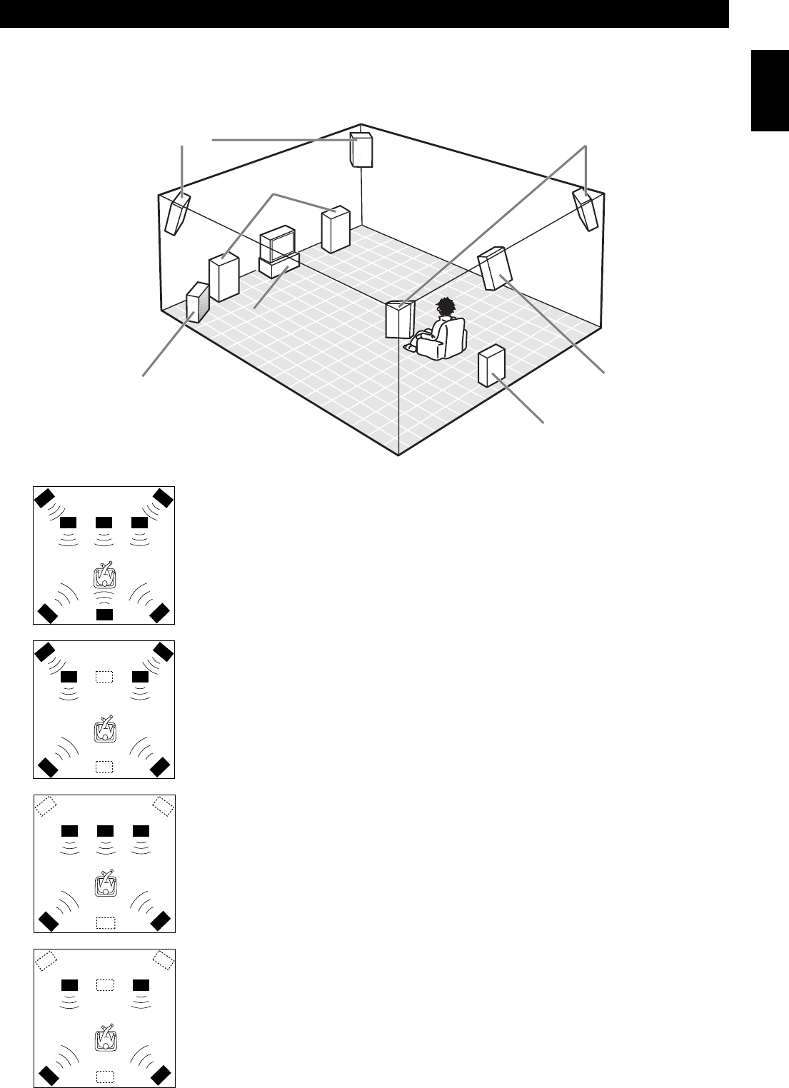
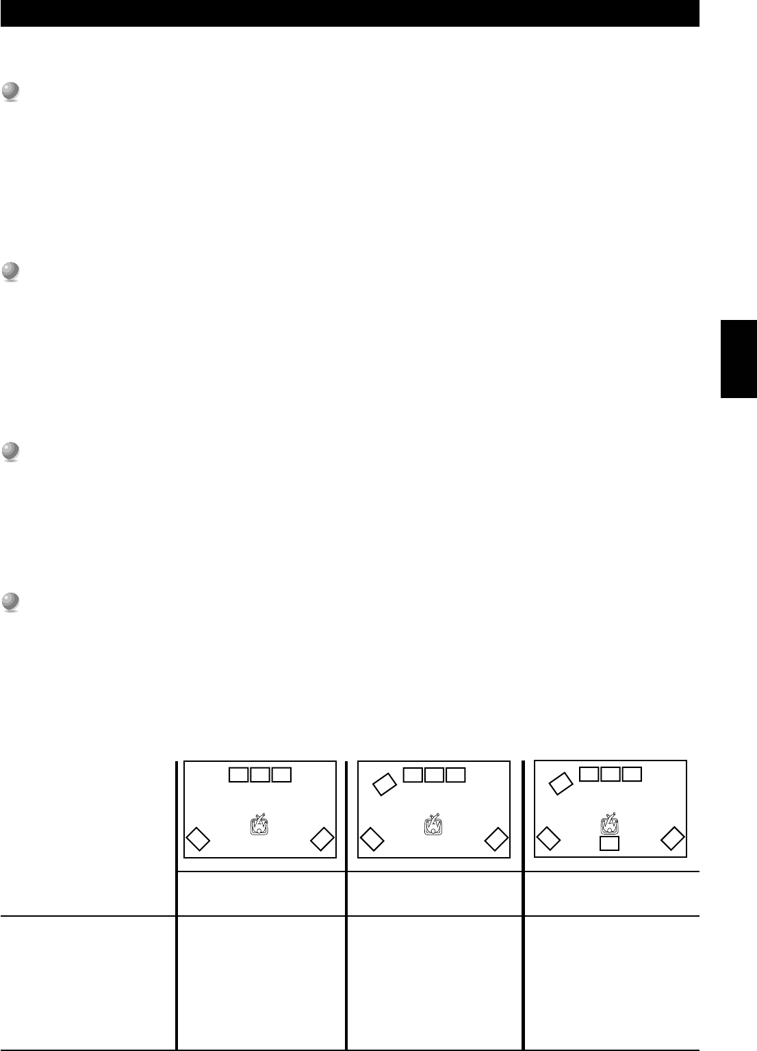
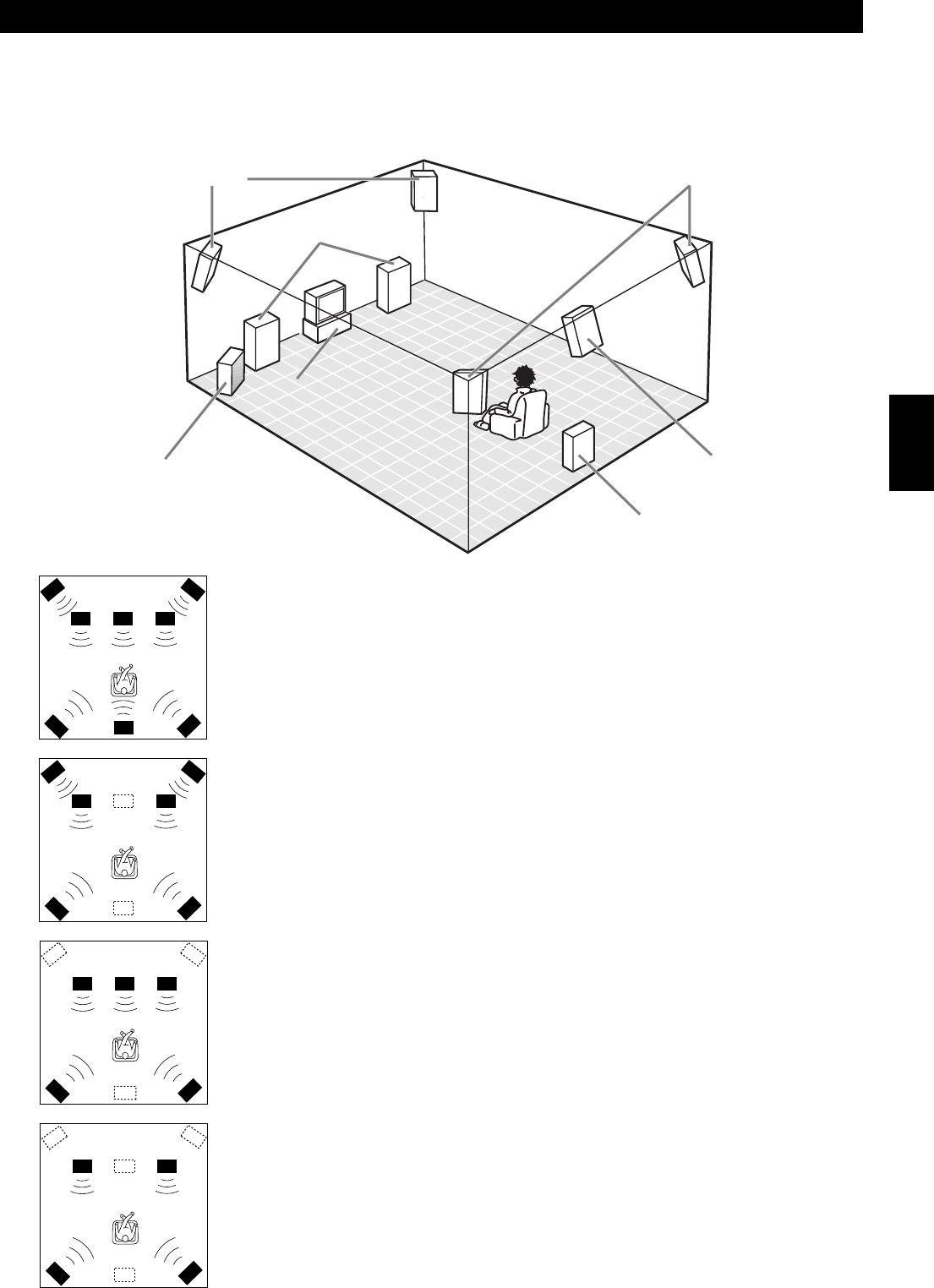
This configuration does not express the height of the sound field as well as the
seven or eight speaker configuration. However, it positions the dialogue sound as
coming directly from the screen.
For this speaker configuration, change SET MENU item 1F. FRNT EFCT SP to
“NONE” and 1D. REAR CT SP to “NONE” (see page 37).
■
Four Speaker Configuration –Minimum Requirement–
In this configuration, the Center speaker signals and Front Effect speaker signals
are directed to the left and right Main speakers.
For this speaker configuration, change SET MENU item 1A. CENTER SP to
“NONE,” item 1F. FRNT EFCT SP to “NONE,” and item 1D. REAR CT SP to
“NONE” (see page 37).
Front Effect Speakers
Front Subwoofer
Center Speaker
Main Speakers
Rear Speakers
Rear Center Speaker
Rear Subwoofer
14
Preparations
FL
L
RL
CR
FR
RR
RC
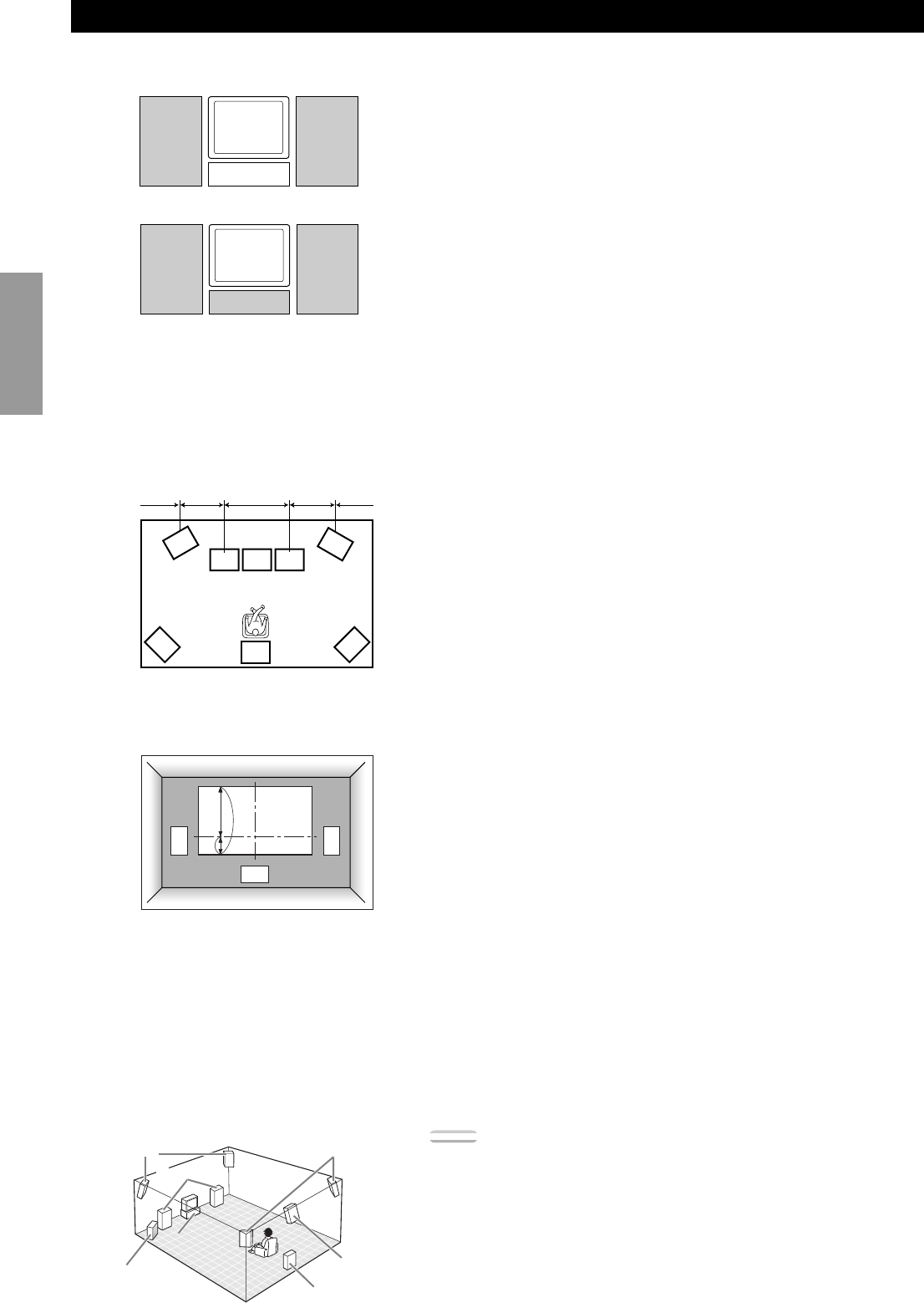
Speaker Placement
Where you place your speakers has a tremendous effect on how well your system sounds.
■Placing the Main Speakers
Place the left and right Main speakers an equal distance from the main listening
position.
If you have a TV or video monitor in your system, the distance of each speaker
from each side of the TV or video monitor should be the same.
■Placing the Center Speaker
If you have a TV or video monitor in your system, align the front face of the
Center speaker with the front face of the monitor. Place the speaker as close to the
monitor as possible, such as directly over or under the monitor. If you place the
speaker under the monitor, the Front Effect speakers can adjust the height of the
sound to correspond with the action on the screen (depending on the listener’s
position). If you have a projection screen in your system, place the Center speaker
under the screen. Be sure to align the speaker with the center of the screen.
■Placing the Front Effect, Rear and Rear Center
Speakers
These speakers should be placed about 0.5~1m (1~3 feet) outside the Main
speakers and in the front of the room. They should be turned toward the main
listening position. Place the Rear speakers in the back of the room so they face the
main listening position. The Rear speakers can be placed farther apart than the
Front Effect speakers. The Front Effect and Rear speakers should be placed about
1.8m (6 feet) above the floor.
Once you begin listening to programs, continue to adjust the speaker placement
until you obtain a balanced sound from the Main speakers and the Front Effect
and Rear speakers.
■When You Use a Projection Screen
Place the speakers as shown in the illustration.
The Main speakers should be placed about one-quarter of the way up from the
bottom of the screen.
Place the Center speaker in the center and directly under the screen. The Center
speaker provides precise dialogue localization.
When you use a projection screen with your system, the Front Effect speakers
provide better effect quality. The CINEMA-DSP sound field programs (see page
34) raise the sound from the Center speaker upward and provide natural sound
corresponding with the video images.
■Placing the Subwoofers
Place the Front Subwoofer near the Main speakers. Turn it slightly toward the center of the room to reduce wall reflections.
If you use a Rear Subwoofer, place it behind the main listening position. The placement of the Rear Subwoofer is not critical because of
the ultralow frequencies of the sound being reproduced.
By adding a high quality Subwoofer to the speaker configurations shown on pages 21 and 22, you can enjoy more powerful and realistic
movie effects, even if your Main speakers are large.
Note:
•If you use different brands of speakers (with different tonal qualities) in your
configuration, the tone of a moving human voice and other types of sound may not
shift smoothly. We recommend that you use speakers from the same manufacturer or
speakers with the same tonal quality.
You can also adjust the output levels and equalization of your effect speakers using the
SET MENU (see page 37).
If you are using small speakers, the addition of a Subwoofer will reinforce the sound
effects of movies (see page 21).
L
C
R
1/4
1
Main
speaker
Main
speaker
TV or Video
monitor
TV or Video
monitor
Center speaker
Front Effect
speakers
Front Subwoofer
Rear Subwoofer
Rear Center
speaker
Rear speakers
Center speaker
1m1m0.5~1m1.5~3m0.5~1m
(3ft)(3ft)(1~3ft)(5~15ft)(1~3ft)
Main speakers
15
English
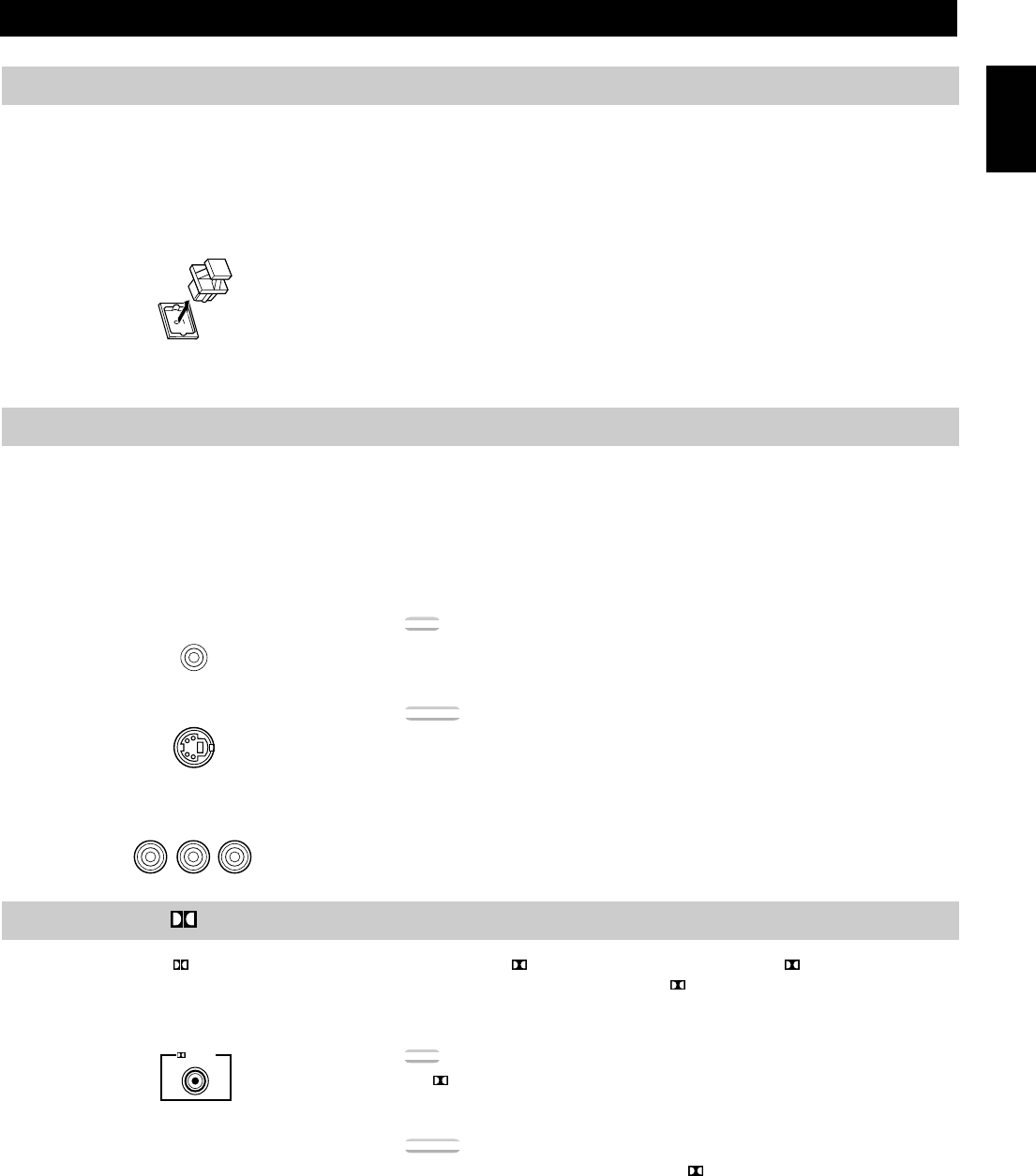
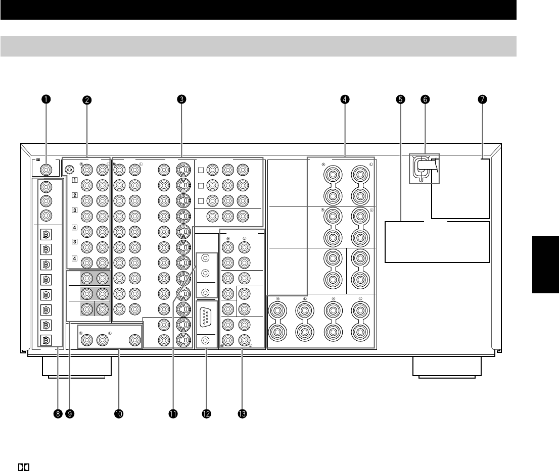
Connecting to Digital Jacks
The DSP-AX1 has digital jacks for direct transmission of digital signals through either coaxial or fiber optic cables. You can use the digital
jacks to input PCM, DTS and Dolby Digital bitstreams. When you connect components to both the COAXIAL and OPTICAL jacks (for CD,
DVD, and CBL/SAT) priority is given to the input signals from the COAXIAL jack. All digital input jacks are acceptable for 96 kHz/24 bit
digital signals.
■About the Dust Protection Cap
Pull out the cap from the optical jack before you connect the fiber optic cable.
Do not discard the cap. When you are not using the optical jack, be sure to put the
cap back in place. This cap protects the jack from dust.
About the Video Jacks
There are three types of video jacks. Video signals input through the VIDEO jacks are the conventional composite video signals. Video
signals input through the S VIDEO jacks are separated into luminance (Y) and color (C) video signals. The S-video signals achieve high
quality color reproduction.
Video signals input through the COMPONENT VIDEO jacks are separated into luminance (Y) and color difference (PB/CB, PR/CR) video
signals. The jacks are also separated into three for each signal. The description of the component video jacks may be different depending on
the component (e.g. Y, CB, CR / Y, PB, PR / Y, B-Y, R-Y/ etc.). Component video signals provide the best quality in picture reproduction.
Note:
•Each type of video jack works independently. Signals input through the composite
video, S-video, and component jacks are output through the corresponding composite
video, S-video, and component jacks respectively.
Caution:
•Use a commercially available S-video cable when connecting to the S VIDEO jacks,
and commercially available video cables when connecting to the COMPONENT
VIDEO jacks.
•When you are using the COMPONENT VIDEO jacks, check the details in the owner’s
manual that came with the component being connected.
About the RF (AC-3) Signal Input Jack
If your LD player has an RF (AC-3) signal output jack, connect it to the RF (AC-3) input jack on this unit. If RF (AC-3) and analog
signals are input at the same time, priority is given to the RF signals. When you want to reproduce RF (AC-3) signals, set the input mode
to “D.D. RF” using INPUT MODE.
Note:
• RF (AC-3) signals cannot be output using the REC OUT selector. When you record
sound or images from an LD player, be sure to connect the player to either the
DIGITAL OPTICAL or analog AUDIO jacks.
Caution:
•Even if you connect an LD player with an RF (AC-3) output jack to this unit, you
cannot reproduce Dolby Digital sound from all LD discs. You must playback an LD
disc encoded with Dolby Digital signals in order to take advantage of the Dolby Digital
sound.
Hookups
RF(AC-3)
LD
P
R
/C
R
P
B
/C
B
Y
Composite VIDEO terminal
S VIDEO terminal
COMPONENT VIDEO terminals
16
Preparations
Hookups
Connecting Audio Components
Before you connect any components, disconnect the power supply to all the components you plan to connect including the DSP-AX1 and
determine which jacks are for the left and right channels and for input and output.
When you connect other YAMAHA audio equipment (such as a CD player or changer, Tuner, MD deck, or tape deck), connect to terminals
with the same number labels. Yamaha applies this labelling system to all its products.
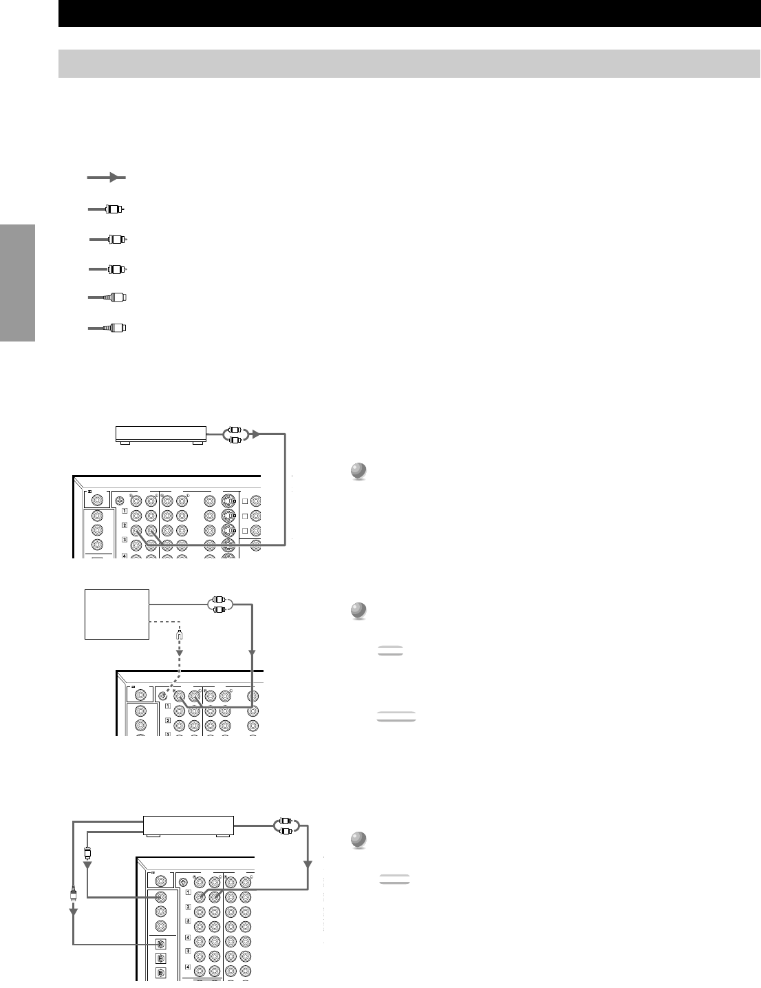
In the hookup illustrations on the following pages:
After you finish all hookups, check them again to make sure they are correct.
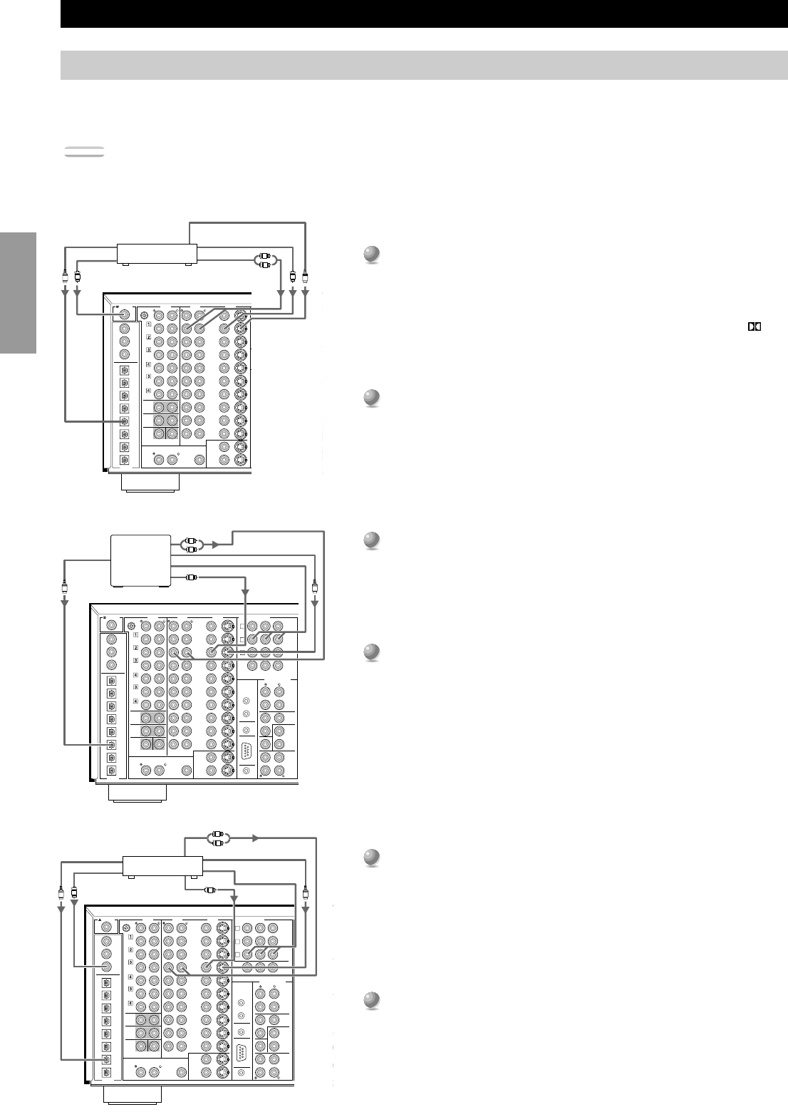
■Connecting an AM/FM Tuner
1
1
Connect the left and right signal output jacks on your tuner
to the TUNER2L and R jacks.
■Connecting a Turntable
1
1
Connect the left and right signal output cords to the PHONOL and
R jacks.
Note:
•These jacks are for connecting a turntable with an MM or high output MC
cartridge. If you have a turntable with a low output MC cartridge, use an inline
boosting transformer or MC-head amplifier when connecting to these jacks.
Caution:
•The GND terminal does not electrically ground the turntable. It simply reduces
noise in the signal. In some cases, you may hear less noise if you do not connect to
the GND terminal.
■Connecting a CD Player
1
1
Connect the left and right analog signal output jacks on your CD
player to the CD1L and R jacks.
Notes:
•The COAXIAL CD and OPTICAL CDjacks are available for a CD player which
has coaxial or optical digital outputs.
•When you connect a CD player to both the COAXIAL CD and OPTICAL CD
jacks, priority is given to the input signals from the COAXIALCD jack.
•The OPTICAL jacks on this unit conform to the EIA standard. If you use a fiber
optic cable that does not conform to this standard, the DSP-AX1 may not function
properly.
TUNER
IN
(
PLAY
)
CD
GND
DVD
VIDEO
LD
D-TV
CBL
/SAT
CD
DVD
LD
CBL
/SAT
AUDIO
PHONO
AUDIOVIDEO
S VIDEO
RF(AC-3)
L
R
TUNER
IN
(PLAY)
CD
GND
TAPE
OUT
(REC)
DVD
VIDEO
LD
D-TV
CBL
/SAT
IN
M
CD
CD
DVD
LD
CBL
/SAT
AUDIO
PHONO
AUDIOVIDEO
S VIDEO
COMPONENT VIDEO
PREOUT/MAI
N
P
R
/
P
B
/C
B
Y
COAXIAL
OPTICAL
RF(AC-3)
A
B
C
L
R
MAIN
TUNER
IN
(PLAY)
IN
(PLAY)
CD
GND
TAPE
OUT
(REC)
OUT
(REC)
MD
VCR 1
VCR 2
DVD
VIDEO
LD
D-TV
CBL
/SAT
IN
IN
IN
OUT
OUT
CD
CD
DVD
DVD
LD
MD
OUT
(REC)
IN
(
PLAY)
CBL
/SAT
AUDIO
PHONO
AUDIOVIDEO
S VIDEO
COMPONE
N
P
Y
OUT
REMOTE 1
COAXIAL
OPTICAL
RF(AC-3)
A
B
C
O
C
L
R
AM/FM Tuner
Audio Output
Turntable
Output
Ground
CD Player
Optical Output
Coaxial Output
Analog
Output
indicates signal direction,
indicates coaxial cables,
indicates left side analog cables,
indicates right side analog cables,
indicates optical cables; and,
indicates S-video cables.
C
O
S
L
R
17
English
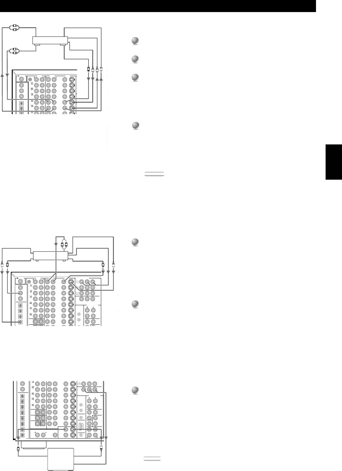
■Connecting a Tape Deck
1
1
Connect the left and right signal output jacks on your tape deck to
the TAPE3(PLAY)L and R jacks.
2
2
Connect the left and right signal input jacks on your tape deck to the
TAPE4(REC)L and R jacks.
Notes:
•You can monitor audio recordings if you connect a three-head tape deck to the
TAPE3(PLAY) jacks.
•When you connect a tape deck to the DSP-AX1, keep the deck’s power on while
using the DSP-AX1. If the power is off, the DSP-AX1 may distort the sound from
other equipment.
•When you record from source equipment connected to the DSP-AX1 while the
DSP-AX1’s power is off, the recorded sound may be distorted. To avoid this
problem, turn on the DSP-AX1.
■Connecting an MD or DAT Deck
1
1
Connect the left and right analog signal output jacks on your MD or
DAT deck to the MD3(PLAY)L and R jacks.
2
2
Connect the left and right analog signal input jacks on your MD or
DAT deck to the MD4(REC)L and R jacks.
3
3
Connect the optical digital signal output jack on your MD or DAT
deck to the OPTICAL MD (PLAY) jack.
4
4
Connect the optical digital signal input jack on your MD or DAT
deck to the OPTICAL MD (REC) jack.
Note:
•When you connect your MD or DAT deck to both the analog and digital input and
output jacks, priority is given to the digital signals.
MAIN
TUNER
IN
(PLAY)
IN
(PLAY)
CD
GND
TAPE
OUT
(REC)
OUT
(REC)
MD
VCR 1
VCR 2
DVD
VIDEO
LD
D-TV
CBL
/SAT
IN
IN
IN
IN
OUT
OUT
CD
CD
DVD
DVD
LD
MD
OUT
(REC)
IN
(
PLAY)
CBL
/SAT
AUDIO
PHONO
AUDIOVIDEO
S VIDEO
COMPONENT VI
P
B
/C
B
Y
M
O
OUT
REMOTE 1
REMOTE 2
COAXIAL
OPTICAL
RF(AC-3)
A
B
C
O
L
R
O
L
R
Hookups
MAIN
SURROUND
TUNER
IN
(PLAY)
IN
(PLAY)
CD
GND
TAPE
OUT
(REC)
OUT
(REC)
MD
VCR 1
VCR 2
DVD
VIDEO
LD
D-TV
CBL
/SAT
IN
IN
IN
OUT
OUT
CD
CD
DVD
DVD
LD
LD
MD
OUT
(REC)
IN
(
PLAY)
CBL
/SAT
AUDIO
PHONO
AUDIOVIDEO
S VIDEO
COAXIAL
OPTICAL
RF(AC-3)
L
R
L
R
Tape Deck
Analog
Input
Analog
Output
MD or DAT Deck
Analog Input
Analog Output
Optical Input
Optical Output
18
Preparations
Connecting Video Components
Before you connect any components, disconnect the power supply to all the components you plan to connect including the DSP-AX1 and
determine which jacks are for the left and right channels and for input and output. After you finish all hookups, check them again to make
sure they are correct.
Note:
•If you make S-video connections to this unit, it is not necessary to make composite video connections. If both types of connections are made, this unit gives
priority to the S-video signal.
■Connecting an LD Player
1
1
Connect the left and right audio signal output jacks on your LD
player to the LDL and R jacks.
If your LD player has an RF signal or optical digital signal outputs, you can
connect them to this unit.
Connect the RF signal output jack on your LD player to the
RF (AC-3)
LD jack.
Connect the optical digital signal output jack on your LD player to the
OPTICAL LD jack.
2
2
Connect the composite video signal output jack on your LD player to
the LD VIDEO jack.
If your LD player has an S-video output, you can connect it to this unit.
Connect the S-video signal output jack on your LD player to the LD
S VIDEO jack.
■Connecting a TV or Digital TV
1
1
Connect the left and right analog signal output jacks on your TV to
the D-TVL and R jacks.
If your TV has an optical digital signal output, you can connect it to this
unit.
Connect the optical digital signal output jack on your TV to the OPTICAL
D-TV jack.
2
2
Connect the composite video signal output jack on your TV to the
D-TV VIDEO jack.
If your TV has an S-video output or component video output, you can
connect it to this unit.
Connect the S-video signal output jack on your TV to the D-TV S VIDEO
jack or connect the component signal output jacks on your TV to the D-TV
COMPONENTVIDEO jacks.
■Connecting a Satellite Tuner or Cable TV Tuner
(Set Top Box)
1
1
Connect the left and right audio signal output jacks on your tuner to
the CBL/SATL and R jacks.
If your tuner has coaxial or optical digital signal outputs, you can connect
them to this unit.
Connect the coaxial digital signal output jack on your tuner to the
COAXIAL CBL/SAT jack.
Connect the optical digital signal output jack on your tuner to the OPTICAL
CBL/SAT jack.
2
2
Connect the composite video signal output jack on your tuner to the
CBL/SAT VIDEOjack.
If your tuner has an S-video or component video output, you can connect it
to this unit. Connect the S-video signal output jack on your tuner to the
CBL/SAT S VIDEO jack or connect the component signal output jacks on
your tuner to the CBL/SAT COMPONENTVIDEO jacks.
MAIN
CENTER
SUB
WOOFER
6CH INPUT
SURROUND
TUNER
IN
(PLAY)
IN
(PLAY)
CD
GND
TAPE
OUT
(REC)
OUT
(REC)
MD
VCR 1
VCR 2
VCR 3
DVD
VIDEO
LD
D-TV
CBL
/SAT
IN
DVD
D-TV
CBL
/SAT
MONITOR
OUT
IN
IN
IN
IN
OUT
OUT
OUT
CD
CD
DVD
DVD
LD
LD
VCR 1
D-TV
MD
OUT
(REC)
IN
(
PLAY)
CBL
/SAT
CBL
/SAT
AUDIO
PHONO
AUDIOVIDEO
S VIDEO
COMPONENT VIDEO
PREOUT/MAIN IN
B
PR/CRPB/CBY
FRONT
REAR
(SURROUND)
SUB
WOOFER
SPLIT
CENTER
IN
CENTER
OUT
MAIN
IN
MAIN
OUT
MONO
REAR CTR
RB-
2320
RS
232C
OUT
REMOTE 1
REMOTE 2
CTRL
OUT
+5V
20mA
100Ω
+
–
ZONE 2 OUTVIDEO
OUT
COAXIAL
OPTICAL
DIGITAL
RF(AC-3)
MONITOR
OUT 1
MONITOR
OUT 2
A
B
C
C
S
O
L
R
Hookups
MAIN
CENTER
SUB
WOOFER
6CH INPUT
SURROUND
TUNER
IN
(PLAY)
IN
(PLAY)
CD
GND
TAPE
OUT
(REC)
OUT
(REC)
MD
VCR 1
VCR 2
VCR 3
DVD
VIDEO
LD
D-TV
CBL
/SAT
IN
DVD
D-TV
CBL
/SAT
MONITOR
OUT
IN
IN
IN
IN
OUT
OUT
OUT
CD
CD
DVD
DVD
LD
LD
VCR 1
D-TV
MD
OUT
(REC)
IN
(
PLAY)
CBL
/SAT
CBL
/SAT
AUDIO
PHONO
AUDIOVIDEO
S VIDEO
COMPONENT VIDEO
PREOUT/MAIN IN
PR/CRPB/CBY
FRONT
REAR
(SURROUND)
SUB
WOOFER
SPLIT
CENTER
IN
CENTER
OUT
MAIN
IN
MAIN
OUT
MONO
REAR CTR
RB-
2320
RS
232C
OUT
REMOTE 1
REMOTE 2
CTRL
OUT
+5V
20mA
ZONE 2 OUTVIDEO
OUT
COAXIAL
OPTICAL
DIGITAL
RF(AC-3)
MONITOR
OUT 1
MONITOR
OUT 2
100Ω
A
B
C
CC
S
O
L
R
MAIN
CENTER
SUB
WOOFER
6CH INPUT
SURROUND
TUNER
IN
(PLAY)
IN
(PLAY)
CD
GND
TAPE
OUT
(REC)
OUT
(REC)
MD
VCR 1
VCR 2
VCR 3
DVD
VIDEO
LD
D-TV
CBL
/SAT
IN
DVD
D-TV
CBL
/SAT
MONITOR
OUT
IN
IN
IN
IN
OUT
OUT
OUT
CD
CD
DVD
DVD
LD
LD
VCR 1
D-TV
MD
OUT
(REC)
IN
(
PLAY)
CBL
/SAT
CBL
/SAT
AUDIO
PHONO
AUDIOVIDEO
S VIDEO
COMPONENT VIDEO
PREOUT/MAIN IN
S
B
P
R
/C
R
P
B
/C
B
Y
FRONT
REAR
(SURROUND)
SUB
WOOFER
SPLIT
CENTER
IN
CENTER
OUT
MAIN
IN
MAIN
OUT
MONO
REAR CTR
RB-
2320
RS
232C
OUT
REMOTE 1
REMOTE 2
CTRL
OUT
+5V
20mA
100Ω
+
–
ZONE 2 OUTVIDEO
OUT
COAXIAL
OPTICAL
DIGITAL
RF(AC-3)
MONITOR
OUT 1
MONITOR
OUT 2
A
B
C
C
S
O
L
R
C
LD Player
Optical
Output
RF-Signal
Output
Analog Audio
Output
Optical
Output
Digital TV/
TV
Analog Audio Output
S-video Output
Video Output
Optical Output
Coaxial Output
Analog Audio Output
S-video Output
Component
Output
Satellite/Cable
TV Tuner
Video Output
Component
Output
S-video Output
Video Output
19
English
Hookups
■Connecting a VCR
1
1
Connect the left and right audio signal output jacks on your VCR to
the VCR 1 INL and R jacks.
2
2
Connect the left and right audio signal input jacks on your VCR to
the VCR 1 OUTL and R jacks.
3
3
Connect the composite video signal output jack on your VCR to the
VCR 1 VIDEO IN jack.
If your VCR has an S-video output, you can connect it to this unit.
Connect the S-video signal output jack on your VCR to the VCR 1 IN S
VIDEO jack.
4
4
Connect the composite video signal input jack on your VCR to the
VCR 1 VIDEO OUT jack.
If your VCR has an S-video input, you can connect it to this unit.
Connect the S-video signal input jack on your VCR to the VCR 1 OUT S
VIDEO jack.
Notes:
•You can connect other VCRs to the DSP-AX1 using the VCR 2 and VCR 3 jacks.
•If your VCR has an optical digital signal output jack, connect it to the OPTICAL
VCR 1 jack of this unit.
■Connecting a DVD Player
1
1
Connect the left and right analog signal output jacks on your DVD
player to the DVDL and R jacks.
If your DVD player has coaxial or optical digital outputs, you can connect
one or both of them to this unit.
Connect the coaxial digital signal output jack on your DVD player to the
COAXIAL DVD jack.
Connect the optical digital signal output jack on your DVD player to the
OPTICAL DVD jack.
2
2
Connect the composite video signal output jack on your DVD player
to the DVD VIDEO jack.
If your DVD player has an S-video output or component video output, you
can connect it to this unit. Connect the S-video signal output jack on your
DVD player to the DVD S-VIDEOjack or connect the component signal
output jacks on your DVD player to the DVD COMPONENT VIDEO
jacks.
■Connecting a Video Monitor
1
1
Connect the composite video signal input jack on your monitor to
MONITOR OUT 1 VIDEO jack.
If your video monitor has an S-video input, you can connect it to this unit.
Connect the S-video signal input jack on your video monitor to the
MONITOR OUT 1 S-VIDEOjack.
If your video monitor has component video signal inputs, you can connect
them to the COMPONENT VIDEO MONITOR OUT jacks.
Note:
•You can connect another monitor to this unit using the MONITOR OUT 2 jacks.
MAIN
CENTER
SUB
WOOFER
6CH INPUT
SURROUND
TUNER
IN
(PLAY)
IN
(PLAY)
CD
TAPE
OUT
(REC)
OUT
(REC)
MD
VCR 1
VCR 2
VCR 3
D-TV
CBL
/SAT
IN
D-TV
CBL
/SAT
MONITOR
OUT
IN
IN
IN
IN
OUT
OUT
OUT
CD
CD
DVD
DVD
LD
VCR 1
D-TV
MD
OUT
(REC)
IN
(
PLAY)
CBL
/SAT
CBL
/SAT
PREOUT/MAIN IN
FRONT
REAR
(SURROUND)
SUB
WOOFER
SPLIT
CENTER
IN
CENTER
OUT
MAIN
IN
MAIN
OUT
MONO
REAR CTR
RB-
2320
RS
232C
OUT
REMOTE 1
REMOTE 2
CTRL
OUT
+5V
20mA
100Ω
ZONE 2 OUTVIDEO
OUT
COAXIAL
OPTICAL
DIGITAL
MONITOR
OUT 1
MONITOR
OUT 2
B
C
S
C
MAIN
TUNER
IN
(PLAY)
IN
(PLAY)
CD
GND
TAPE
OUT
(REC)
OUT
(REC)
MD
VCR 1
VCR 2
DVD
VIDEO
LD
D-TV
CBL
/SAT
IN
DVD
D-TV
CBL
/SAT
MONITOR
OUT
IN
IN
OUT
OUT
CD
CD
DVD
DVD
LD
MD
OUT
(REC)
IN
(
PLAY)
CBL
/SAT
AUDIO
PHONO
AUDIOVIDEO
S VIDEO
COMPONENT VIDEO
PREOUT/MAIN IN
S
PR/CRPB/CBY
FRONT
REAR
(SURROUND)
SUB
WOOFER
SPLIT
MONO
OUT
REMOTE 1
REMOTE 2
COAXIAL
OPTICAL
RF(AC-3)
A
B
C
CC
OS
L
R
MAIN
CENTER
SUB
WOOFER
6CH INPUT
SURROUND
TUNER
IN
(PLAY)
IN
(PLAY)
CD
GND
TAPE
OUT
(REC)
OUT
(REC)
MD
VCR 1
VCR 2
VCR 3
DVD
VIDEO
LD
D-TV
CBL
/SAT
IN
DVD
D-TV
CBL
/SAT
MONITOR
OUT
IN
IN
IN
IN
OUT
OUT
OUT
CD
CD
DVD
DVD
LD
LD
VCR 1
D-TV
MD
OUT
(REC)
IN
(
PLAY)
CBL
/SAT
CBL
/SAT
AUDIO
PHONO
AUDIOVIDEO
S VIDEO
COMPONENT VIDEO
PREOUT/MAIN IN
PR/CRPB/CBY
FRONT
REAR
(SURROUND)
SUB
WOOFER
SPLIT
CENTER
IN
CENTER
OUT
MAIN
IN
MAIN
OUT
MONO
REAR CTR
RB-
2320
RS
232C
OUT
REMOTE 1
REMOTE 2
CTRL
OUT
+5V
20mA
100Ω
ZONE 2 OUTVIDEO
OUT
COAXIAL
OPTICAL
DIGITAL
RF(AC-3)
MONITOR
OUT 1
MONITOR
OUT 2
A
B
C
C
L
R
L
R
C
S
S
VCR
Audio Input
Audio Output
Video Input
S-video Input
S-video
Output
Analog Audio Output
Optical Output
Coaxial Output
DVD player
S-video Output
Component Output
Video Output
Video
Monitor
Video Input
S-video
Input
Component
Input
Video Output
20
Preparations
Connecting Speakers
This section explains how to connect speakers to the DSP-AX1. After you finish connecting your speakers, use the SET MENU to change
the signal output settings according to the number and size of the speakers in your configuration.
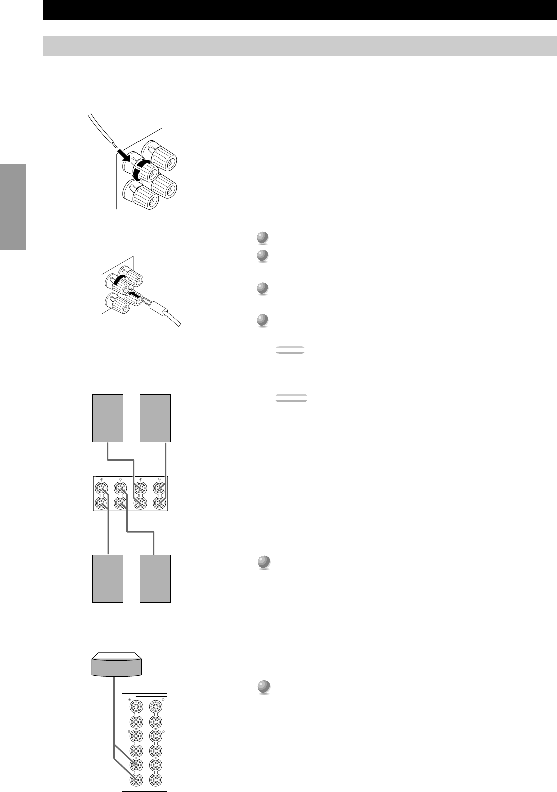
■Using Speaker Cords
A speaker cord is actually a pair of insulated cables running side by side. One of
the cables is colored or shaped differently, perhaps with a stripe, groove or ridge.
To make sure you always connect speakers with the correct polarity, determine
the difference between the cables of your speaker cord, make a note of which
cable you plan to use for which polarity (+ and –), and always connect the speaker
cords consistently.
1
1
Strip off 9 mm (3/8 in.) of insulation from the ends of the cables.
2
2
Twist the exposed wires of the cable together to prevent short
circuits.
3
3
Loosen the terminal knob by turning it counterclockwise.
4
4
Insert only the exposed portion of the cable into the slot in the side of
the terminal, and tighten the terminal knob.
Note:
•If your speaker cords have banana plugs, tighten the terminal knob and insert the
plug into the end of the terminal. (Except for Europe and UK Models)
Caution:
•Connect the speaker cords with care to avoid creating a short circuit. If you turn on
the power and there is a short circuit, this unit may be damaged even though the
protection circuit automatically shuts off the power.
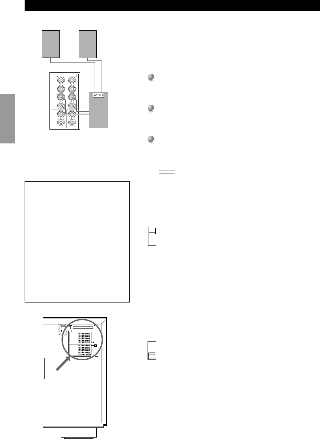
■Connecting the Main Speakers
Before connecting any speaker cords, identify which terminals are for the right
and left channels and also the + and – polarities. If you connect speakers with the
wrong polarity (+ to –), the DSP-AX1 will not reproduce clear sound.
Connect the + and – terminals of your right and left Main speakers to
the L and RMAIN+ and – terminals on this unit.
■Connecting the Center Speaker
Connect the + terminal of your Center speaker to the CENTER +
terminal and the – terminal of your Center speaker to the CENTER –
terminal.
Hookups
AMAINB
+
–
+
–
+
–
S
PEAKERS
FRONT
REAR
CENTERREAR CENTER
+
–
+
–
+
–
+
–
+
–
+
–
BANANA PLUG
[Except for Europe and UK models]
Right Main
Speaker A
Left Main
Speaker A
Right Main
Speaker B
Left Main
Speaker B
Center Speaker
21
English
IN
IN
PREOUT/MAIN IN
FRONT
REAR
(SURROUND)
SUB
WOOFER
SPLIT
CENTER
IN
CENTER
OUT
MAIN
IN
MAIN
OUT
MONO
REAR CTR
RB-
2320
RS
232C
OUT
REMOTE 1
REMOTE 2
CTRL
OUT
+5V
20mA
100Ω
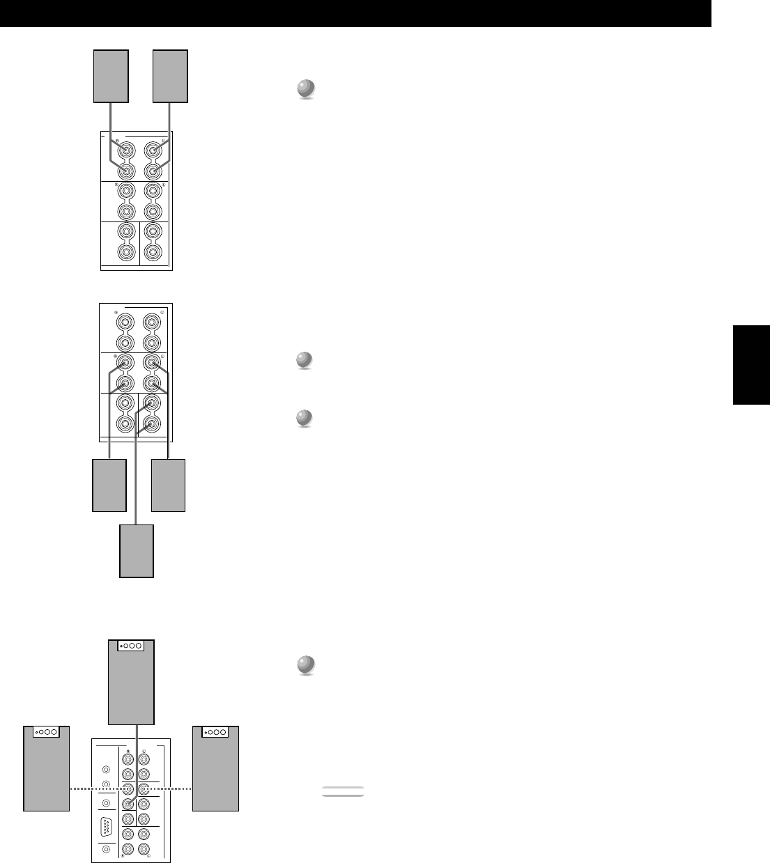
■Connecting the Front Effect Speakers
Connect the + and – terminals of your right and left Front Effect
speakers to the L and RFRONT + and – terminals on this unit.
■Connecting the Rear and Rear Center Speakers
1
1
Connect the + and – terminals of your right and left Rear speakers to
the L and RREAR + and – terminals on this unit.
2
2
Connect the + terminal of your Rear Center speaker to the REAR
CENTER + terminal and the – terminal of your Rear Center speaker
to REAR CENTER – terminal.
■Connecting a Front Subwoofer
Connect the signal input jack on your subwoofer to the PRE OUT/
MAIN IN SUBWOOFER MONO jack.
By connecting two Subwoofers to the SUBWOOFER SPLIT jacks, this
unit can reproduce subtle directional changes in the low frequency sounds.
When you use two Subwoofers, connect both of them to the SUBWOOFER
SPLIT jacks using pin plugs.
Caution:
•The SUBWOOFER jacks (output) have a built-in high cut-off filter (90 Hz). When
using a powered subwoofer, set the high cut-off frequency to “MAX” on your
Subwoofer.
Hookups
SPEAKERS
FRONT
REAR
CENTERREAR CENTER
+
–
+
–
+
–
+
–
+
–
+
–
SPEAKERS
FRONT
REAR
CENTERREAR CENTER
+
–
+
–
+
–
+
–
+
–
+
–
Right Front
Effect Speaker
Left Front
Effect Speaker
Right Rear
Speaker
Left Rear
Speaker
Rear Center Speaker
Subwoofer system
Right
Subwoofer
system
Left
Subwoofer
system
22
Preparations
Hookups
■Connecting a Rear Subwoofer
By using both Front and Rear Subwoofers, the CINEMA-DSP sound field
programs can produce realistic movie effects with powerful, dynamic sound. To
take advantage of this dynamic sound, be sure to set the 1C. REAR L/R SP item
in the SET MENU to “LARGE” (see page 37), and connect your Rear speakers
and Subwoofer as shown below.
1
1
Connect the right + input terminal on your Subwoofer to the REAR
R+ terminal, and the right – input terminal on your Subwoofer to
the REARR– terminal with speaker cords.
2
2
Connect the left + input terminal on your Subwoofer to the REAR
L+ terminal, and the left – input terminal on your Subwoofer to the
REARL– terminal with speaker cords.
3
3
Connect your Rear speakers to the output terminals on the Rear
Subwoofer.
Be sure to connect the Rear speakers to the Subwoofer with the correct
polarity.
Note:
•Adjust the speaker volume for the Subwoofer with the controls on the Subwoofers,
not on the DSP-AX1.
■Impedance Selector switch
Select the position whose requirements your speaker system meets.
(Upper position)
Front Effect:
The impedance of each speaker must be 6Ω or higher.
Rear:The impedance of each speaker must be 4Ω or higher.
Rear Center:
The impedance of the speaker must be 4Ω or higher.
Center:The impedance of the speaker must be 4Ω or higher.
Main:If you use one pair of main speakers, the impedance of each
speaker must be 4Ω or higher.
If you use two pairs of main speakers, the impedance of each
speaker must be 8Ω or higher.
(Lower position)
Front Effect:
The impedance of each speaker must be 8Ω or higher.
Rear:The impedance of each speaker must be 8Ω or higher.
Rear Center:
The impedance of the speaker must be 8Ω or higher.
Center:The impedance of the speaker must be 8Ω or higher.
Main:If you use one pair of main speakers, the impedance of each
speaker must be 8Ω or higher.
If you use two pairs of main speakers, the impedance of each
speaker must be 16Ω or higher.
SPEAKERS
FRONT
REAR
CENTERREAR CENTER
+
–
+
–
+
–
+
–
+
–
+
–
IMPEDANCE SELECTOR
SET BEFORE POWER ON
FRONT
REAR
REAR CENTER
CENTER
MAIN A OR B
A + B
FRONT
REAR
REAR CENTER
CENTER
MAIN A OR B
A + B
WARNING
Do not change the IMPEDANCE
SELECTOR switch setting while the power
to this unit is on, otherwise this unit may be
damaged.
IF THIS UNIT FAILS TO TURN ON
WHEN THE STANDBY/ON SWITCH IS
PRESSED:
The IMPEDANCE SELECTOR switch
may not be set to either end. If so, set the
switch to either end when this unit is in the
standby mode.
(General Model)
Right Rear
Speaker
Left Rear
Speaker
Subwoofer
system
23
English
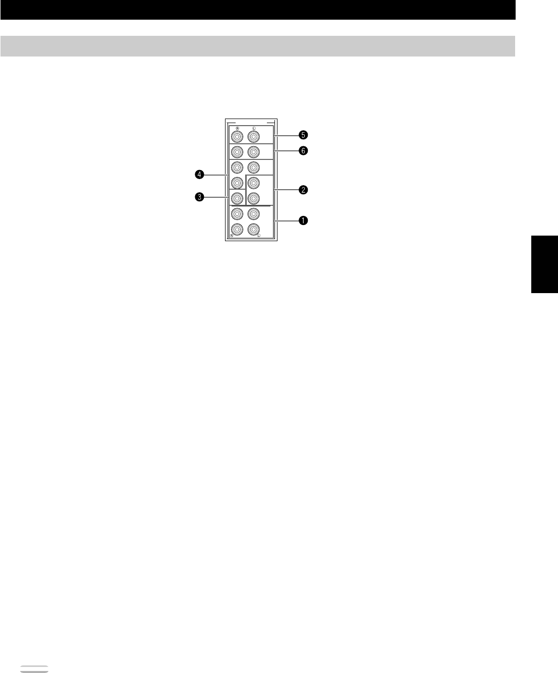
Connecting External Amplifiers
If you want to increase the power output to the speakers, or want to use another amplifier, connect an external amplifier to the PRE OUT/
MAIN IN terminals as follows.
~MAIN jacks
MAIN OUT jacks.....Main channel line output jacks.
The signals output through these jacks
are affected by BASS, TREBLE,
BALANCE, and BASS EXTENSION
settings.
MAIN IN jacks .......... Line input to the DSP-AX1 Main
channel amplifiers.
ŸCENTER jacks
CENTER OUT jack. Center channel line output jacks.
CENTER IN jack.....Line input to the DSP-AX1 Center
channel amplifier.
!REAR CT jack
Rear Center channel line output jack.
PREOUT/MAIN IN
FRONT
REAR
(SURROUND)
SUB
WOOFER
SPLIT
CENTER
IN
CENTER
OUT
MAIN
IN
MAIN
OUT
MONO
REAR CTR
Hookups
Note:
•When RCA pin plugs are connected to the PRE OUT/MAIN IN output jacks for output to external amplifiers, the corresponding internal amplifiers
will be muted.
⁄SUBWOOFER jacks
Subwoofers reinforce very low frequencies.
MONO......................Main, Center and Rear channel
frequencies below 90 Hz are output
through this jack. You can also direct
DTS and Dolby Digital LFE signals to
this output.
SPLIT ....................... The SPLIT jacks output stereo
separation for the Main and Rear
channels and a split mono signal for the
Center and LFE channels.
Adjust the volume level of the subwoofer with the control on
the subwoofer. Subwoofer volume cannot be adjusted from
this unit. Depending on the settings in SET MENU items
1. SPEAKER SET, 3A. LFE LEVEL and 4A. LFE LEVEL,
some signals may not be output from the SUBWOOFER
jacks.
@FRONT
Front Effect channel line output jacks.
¤REAR (SURROUND)
Rear channel line output jacks.
24
Preparations
Connecting Power Supply Cords
■Connecting the AC Power Cord
After completing all connections, plug the AC power cord into a convenient AC
outlet.
■AC OUTLETS
Use these to connect the power cords from your other components to this unit.
The power to the switched outlets is controlled by this unit’s STANDBY/ON
(SYSTEM POWER ON or STANDBY on the remote). These outlets will
supply power to any connected unit whenever this unit is turned on. The
maximum power (total power consumption of components) that can be connected
to AC OUTLETS is 100W.
■VOLTAGE SELECTOR (General and China Models)
The voltage selector on the rear panel of this unit must be set for your local
voltage before plugging into the AC main supply.
Voltages are 110/120/220/240 V AC, 50/60 Hz.
AC OUTLETS
IMPEDANCE SELECTOR
VOLTAGE SELECTOR
Hookups
Connecting an External Decoder
The DSP-AX1 is equipped with six additional input jacks (left and right MAIN, CENTER, left and right SURROUND and SUBWOOFER)
for discrete multi-channel input from an external decoder, sound processor, or pre-amplifier.
Connect the output jacks on your external decoder to the 6CH
INPUT jacks.
Be sure to match the left and right outputs to the left and right input jacks for
the main and surround channels.
To listen to the sound from your external decoder, press 6CH INPUT on this
unit or the remote control.
Note:
•When you select 6CH INPUT as the input source, this unit automatically turns off
the digital sound field processor, and you cannot listen to DSP programs.
MAIN
CENTER
SUB
WOOFER
6CH INPUT
SURROUND
DVD
LD
VCR 1
D-TV
CBL
/SAT
ZONE 2 OUTVIDEO
OUT
DIGITAL
L
R
L
R
C
C
(General Model)
Subwoofer Output
External Decoder
Center Output
Main Output
Surround Output
AC Power Cord
AC OUTLETS
VOLTAGE
SELECTOR
25
English
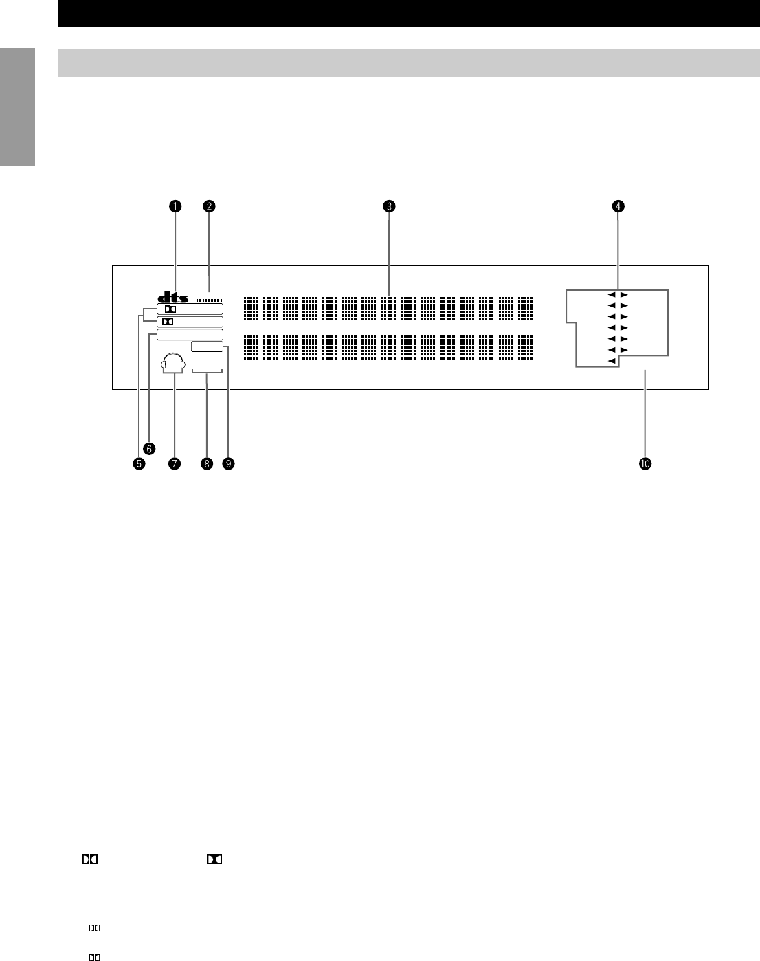
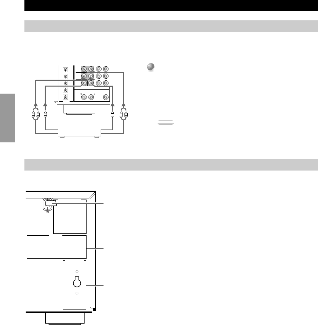
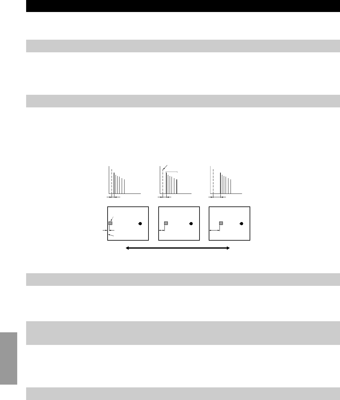
On-Screen Displays (OSD)
You can display the operation information for this unit on a video monitor. If you display the SET MENU and DSP sound field program
parameter settings on a screen, it is much easier to see the available options and parameters than it is by reading this information on the front
panel display.
If a video source is being reproduced, the OSD is superimposed over the image.
If a video source is not being reproduced (or the power of the source equipment is off), the OSD is shown on a blue background.
OSD Modes
You can change the amount of information the OSD shows.
Full Display..............This mode always shows the sound field program parameter settings on the
video monitor (see page 73).
Short Display............This mode briefly shows the same contents as the front panel display at the
bottom of the screen, then disappears.
Display Off...............This mode briefly shows the “DISPLAY OFF” message at the bottom of the
screen, then disappears. Afterwards, no changes to operations appear on the
screen except those of the ON SCREEN.
Notes:
•When you choose the Full Display mode, INPUT SELECTOR, VOLUME and some
other types of operation information are displayed at the bottom of the screen in the
same format as the front panel display.
•The OSD signal is not output through the REC OUT Selector, and will not be recorded
with any video signal.
•The SET MENU, TEST DOLBY SUR and TEST DSP appear regardless of the OSD
mode.
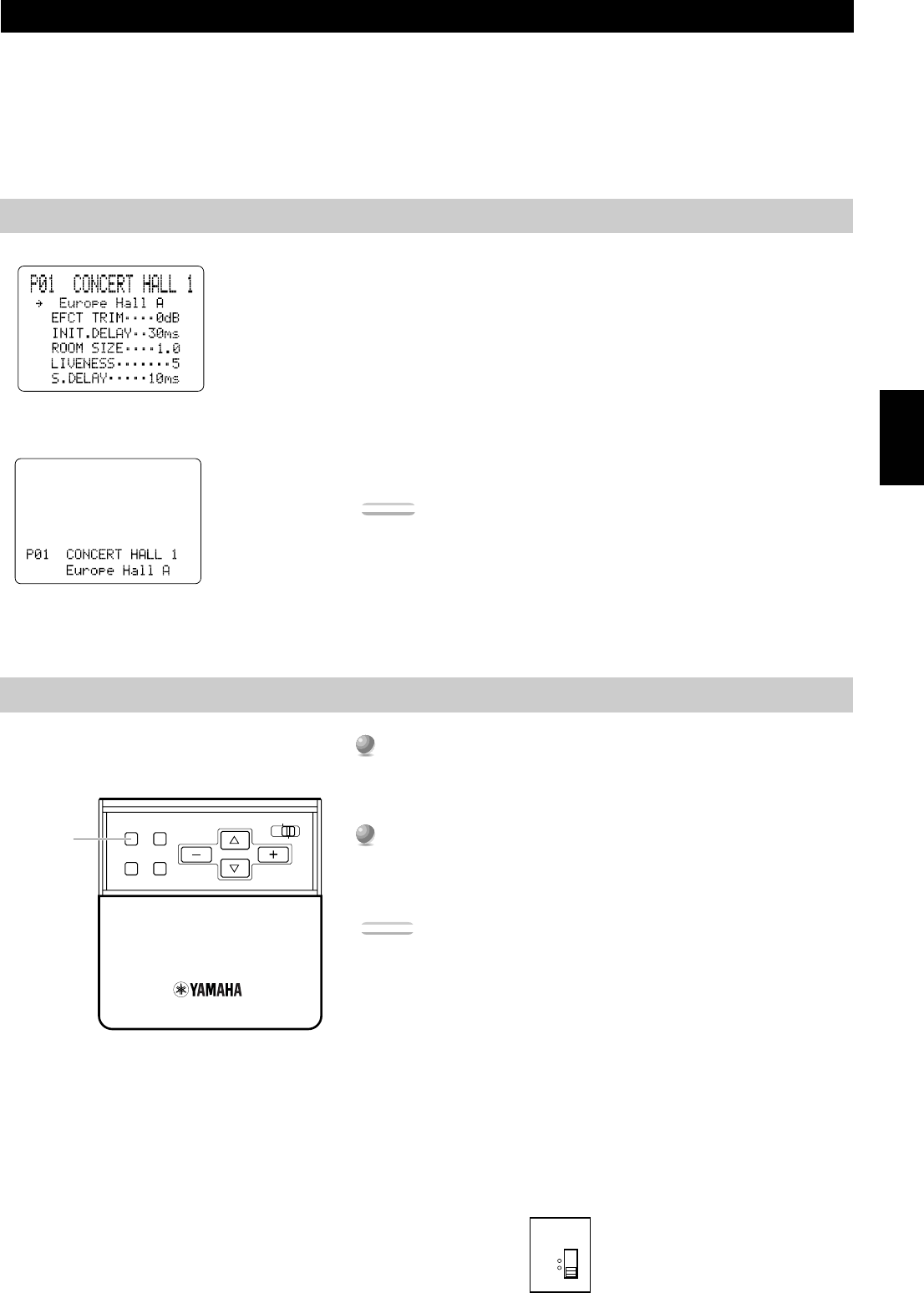
Selecting the OSD Mode
1
1
When you turn on the power, the video monitor and front panel
display shows the level of the main volume for a few seconds and
then switches to show the current sound field program.
2
2
Press ON SCREEN on the remote control repeatedly to change the
display mode.
The OSD mode changes in the following order: Full Display, Short
Display, and Display Off.
Caution:
•If you choose a video input source that has equipment connected to both the S VIDEO
IN and composite VIDEO IN jacks, and both the S VIDEO OUT and composite
VIDEO OUT jacks are connected to a video monitor, the video signal is output to both
the S VIDEO OUT and VIDEO OUT jacks. However, the OSD is carried only on the
S-video signal. If no video signal is input, the OSD is carried on both the S-video and
composite video signals.
•If your video monitor is connected only to the COMPONENT VIDEO terminals of
this unit, the OSD is not shown. Make sure to connect your video monitor to the
COMPONENT VIDEO terminal and either VIDEO or S VIDEO terminals if you
would like to see the OSD.
•Playing back video software that has an anti-copy signal or video signals with a lot of
noise may produce unstable images.
■PAL/NTSC Switch (For General and China Models)
This unit is designed for use with both the NTSC and PAL television formats. Set
this switch to the position compatible with your TV.
ON SCREEN
LEVEL
SLEEPTEST
PARAMETER
SET MENU
PAL
NTSC
Full Display
Short Display
ON SCREEN
26
Preparations
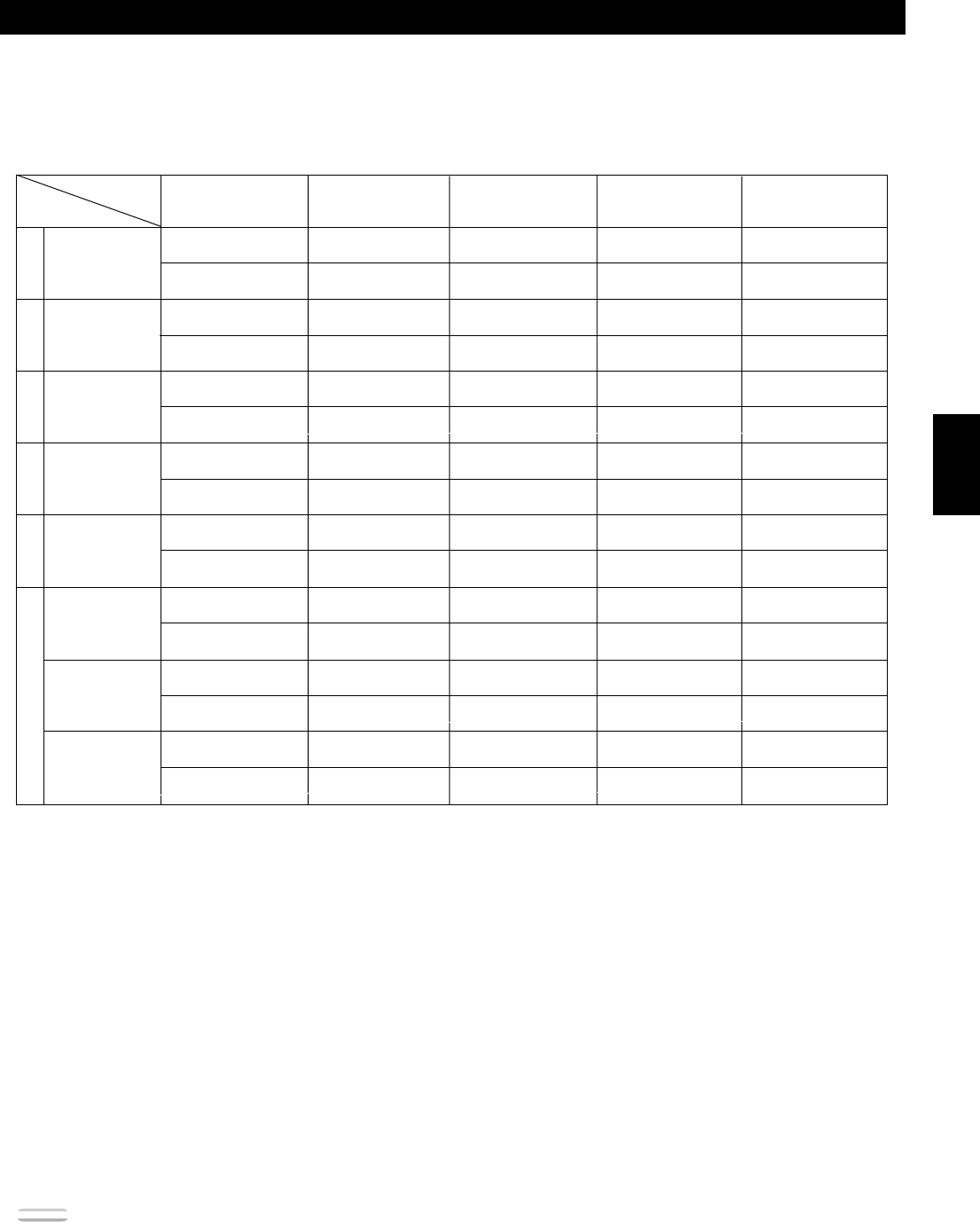
Speaker Settings
The DSP-AX1 has seven SPEAKER SET items in the SET MENU that you must set according to the number of speakers in your
configuration and their size. The following table summarizes these SPEAKER SET items, and shows the initial settings as well as other
possible settings.
If the initial settings are not appropriate for your speaker configuration, change the settings in the SET MENU (see page 37).
Summary of SPEAKER SET items 1A through 1G
Item
Selects the Center channel output mode according to the size of the Center speaker.
The possible settings are LRG (large), SML (small) and NONE.
Selects the Main channel output mode according to the size of the Main speakers.
The possible settings are LARGE and SMALL.
Selects the Rear channel output mode according to the size of the Rear speakers.
The possible settings are LRG (large), SML (small) and NONE.
Selects the Rear center channel output according to the size of the Rear Center speaker.
The possible settings are LRG (large), SML (small) and NONE.
Selects a speaker for the LFE/Bass signal output.
The possible settings are SW (subwoofer), MAIN, and BOTH.
Selects the Front Effect signal output mode for the Front Effect signals.
The possible settings are YES and NONE.
Selects the output level for the Main channel signal.
The possible settings are Normal and –10 dB.
Initial SettingDescription
1A. CENTER SP
1B. MAIN SP
1C. REAR L/R SP
1D. REAR CT SP
1E. LFE/BASS OUT
1F. FRNT EFCT SP
1G. MAIN LEVEL
LRG
LARGE
LRG
LRG
BOTH
YES
Normal
27
English
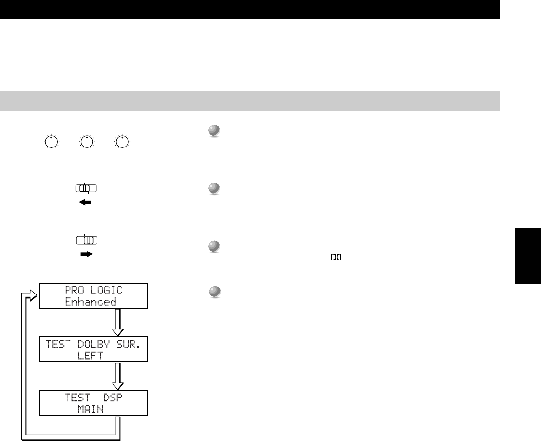
Before You Begin
1
1
Set BASS, TREBLE and BALANCE on the front panel to “0” (the
center position) and turn off BASS EXTENSION.
2
2
Sit in the main listening position and set PARAMETER/SET
MENU on the remote control to PARAMETER.
3
3
Set 10KEY/DSP on the remote control to DSP and press / DTS
SUR.
4
4
Press TEST on the remote control once or twice to select the test
you want.
•Select “TEST DOLBY SUR.” to match the output levels of the Center, Rear
Center and left and right Rear speakers to the left and right Main speakers.
•Select “TEST DSP” to match the output levels of the Front Effect speakers
to the Main speakers.
Speaker Output Levels
This section explains how to set the speaker output levels using the test tone generator. The Dolby Surround test is for balancing the output
levels of the six speakers required for surround sound systems. The DSP test is for balancing the Front Effect speakers with the Main
speakers for the DSP sound field programs.
BASSTREBLE
55
44
33
22
11
0
+
–
55
44
33
22
11
0
+
–
55
44
33
22
11
0
RL
BALANCE
10KEYDSP
PARAMETER
SET MENU
28
Preparations
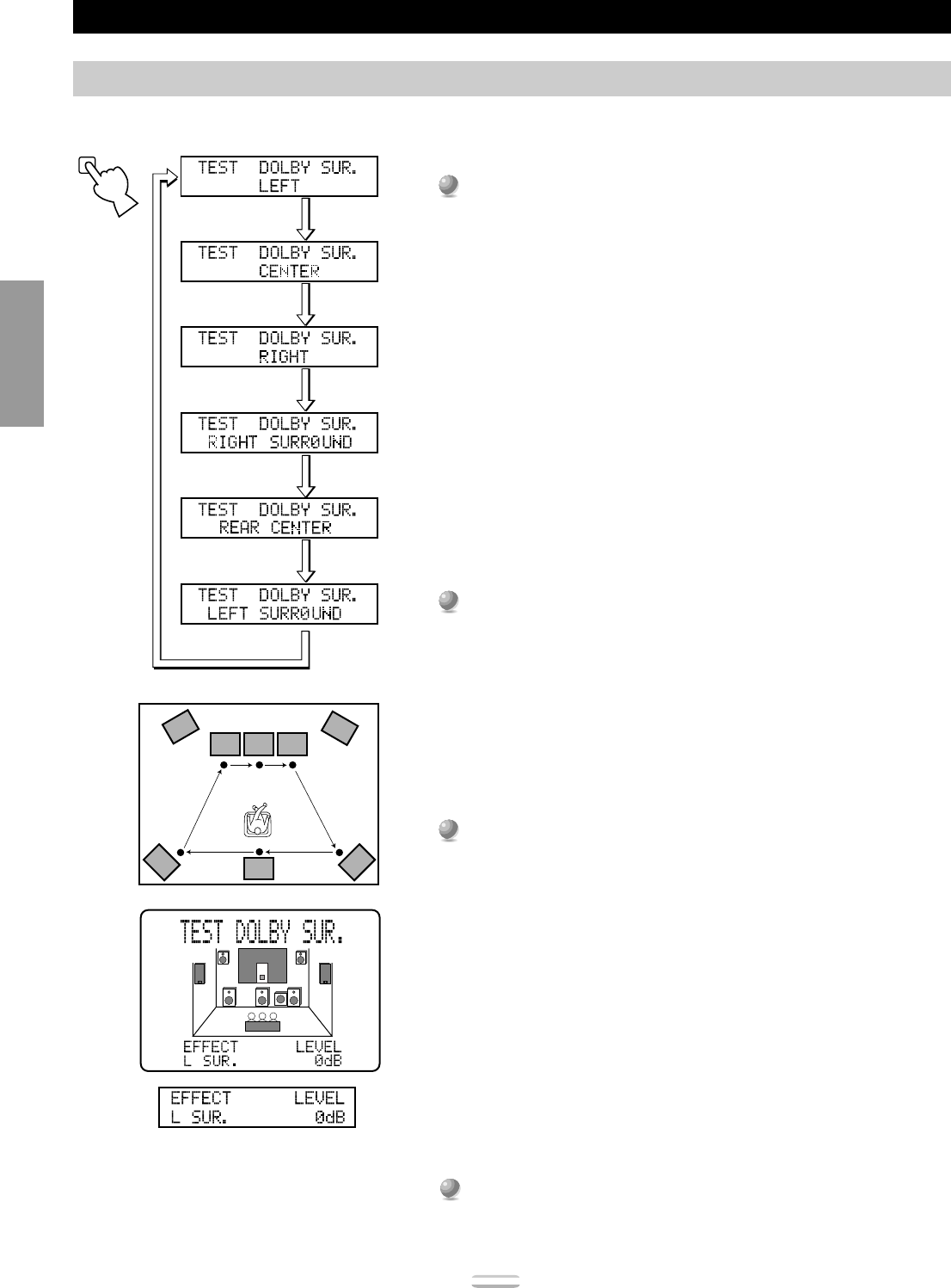
Speaker Output Levels
Dolby Surround Test
Use the Dolby Surround Test to balance the output levels of speakers required for surround sound systems.
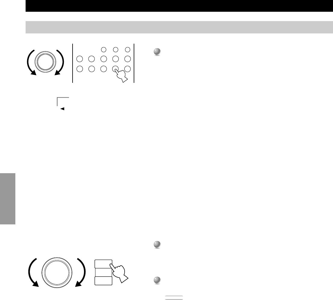
1
1
Press TEST on the remote control so “TEST DOLBY SUR.”
appears on the video monitor and front panel display.
2
2
Adjust VOLUME +/– so you can hear the test tone.
•The test tone is produced from the left Main speaker, Center speaker, right
Main speaker, right Rear speaker, Rear Center speaker and left Rear
speaker in order. The tone is produced for 2.5 seconds each time.
•You can stop the sequence temporarily by pressing
%
or
%
.
3
3
Adjust the output level of the effect speakers using the cursor – or +
buttons on the remote control so the output level coming from each
speaker is the same.
•You can increase the output levels of the effect channels (left Rear, right
Rear, Rear Center and Center) to +10 dB. If the output level of the Center,
Rear, and Rear Center speakers is lower than that from the Main speakers
even after you have increased the sound volume level of the Center, Rear,
and Rear Center speakers up to +10 dB, set the 1G. MAIN LEVEL item in
the SET MENU to “–10dB.” Setting the 1G. MAIN LEVEL item to this
setting decreases the Main speaker volume level to about one-third the
normal level. After you set the 1G. MAIN LEVEL item in the SET
MENU to “–10dB,” adjust the levels for the Center, Rear, and Rear Center
speakers again.
4
4
When you finish adjusting the output level of the Center, Rear, and
Rear Center speakers, press TEST repeatedly until the current DSP
program appears.
Note:
•The tonal quality of the speakers can be adjusted using the 7. CENTER GEQ, 8.
REAR CT GEQ, and 9. CINEMA EQ items in the SET MENU (see page 45~46).
FL
L
RL
C
RC
R
FR
RR
TEST
29
English
1
1
2
2
3
3
4
4
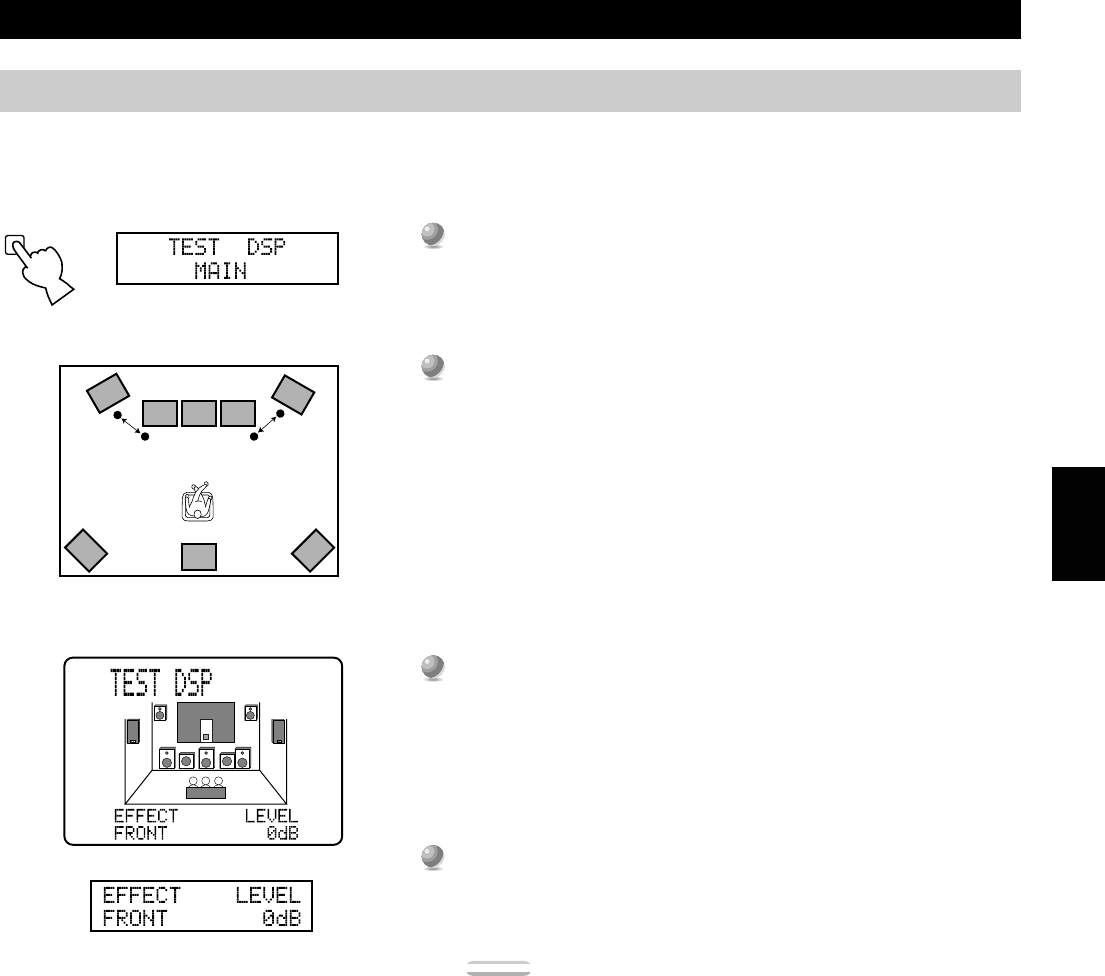
Speaker Output Levels
DSP Test
Adjust the output level of the Front Effect speakers while this unit is reproducing a DSP sound field program. If you do not use Front Effect
speakers, set the 1F. FRNT EFCT SP item in the SET MENU to “NONE” (see page 37), and the DSP Front Effect signals will be mixed with
the Main channel signals.
Press TESTrepeatedly until “TEST DSP” appears on the video
monitor and front panel display.
Adjust VOLUMEso you can hear the test tone.
•The test tone is produced alternately from the Front Effect speakers and Main
speakers. The tone is produced for 2.5 seconds each time.
Adjust the output level of the Front Effect speakers using + and – so the
output level coming from the Front Effect speakers is the same as that
of the Main speakers.
•The test tone is automatically produced from the Front Effect speakers while
you are adjusting the level.
When you finish adjusting the output level of the Front Effect speakers,
press TESTrepeatedly until the current DSP program appears.
Notes:
•If you cannot hear the test tone, set VOLUME, turn off the power, and check the
speaker cords and hookups.
•The test tone can be reproduced separately from the left and right Front Effect
speakers. This is useful when you want to check the hookups to these speakers.
Press
%
to reproduce the test tone from the left speaker, and press
%
to reproduce the
tone from the right speaker. (The OSD shows which speaker is reproducing the tone.)
•You cannot adjust the output level of the left and right Front Effect speakers separately.
•You can stop the test tone’s alternation temporarily by pressing
%
or
%
.
•The tonal quality of the speakers can be adjusted using the 7. CENTER GEQ, 8. REAR
CT GEQ, and 9. CINEMA EQ items in the SET MENU (see page 45~46).
•If the sound volume of the Front Effect speakers is lower than that of the Main
speakers, even after you have increased the output level up to +10 dB, set the 1G.
MAIN LEVEL item in the SET MENU to “–10dB.” Setting the 1G. MAIN LEVEL
item to “–10dB” decreases the Main speaker output level to about one-third of the
normal level.
After you set the 1G. MAIN LEVEL item in the SET MENU to “–10dB,” repeat the
TEST DOLBY SUR. procedure on the previous page.
TEST
FL
L
RL
C
RC
R
FR
RR
30
Basic Operation
Basic Operation
Basic Playback31
Power Control ................................................................................................... 31
Selecting a Source.............................................................................................32
Input Modes and Indications............................................................................. 33
Selecting a Sound Field Program...................................................................... 34
Remote Control in ZONE 2 .............................................................................. 65
37
English
Items
1.SPEAKER SET
1A. CENTER SP
1B. MAIN SP
1C. REAR L/R SP
1D. REAR CT SP
1E. LFE/BASS OUT
1F. FRNT EFCT SP
1G. MAIN LEVEL
2.LOW FREQ. TEST
3.DOLBY D. SET
3A. LFE LEVEL
3B. D-RANGE
4.DTS SET
4A. LFE LEVEL
5.SP DELAY TIME
6.AUDIO DELAY
7.CENTER GEQ
8.REAR CT GEQ
9.CINEMA EQ
9A. L, C, R EQ
9B. FRNT EFCT EQ
9C. REAR L/R EQ
9D. REAR CT EQ
10.HP TONE CTRL
11.PARAMETER INI
12.6.1/ES AUTO
13.MEMORY GUARD
14.CMPNT-V INPT
15.INPUT MODE
16.INPUT RENAME
17.DIMMER
18.ZONE 2 SET
Descriptions
Selects the output mode suitable for your Center speaker.
Selects the output mode suitable for your Main speakers.
Selects the output mode suitable for your Rear speakers.
Selects the output mode suitable for your Rear Center speaker.
Selects the speakers for your LFE/BASS signal output.
Selects the output mode for your Front Effect speakers.
Selects the output level for your main channels.
Matches the Subwoofer level with the level of the other speakers.
Adjusts the output level of the LFE channel for Dolby Digital signals.
Adjusts the dynamic range for Dolby Digital signals.
Adjusts the output level of the LFE channel for DTS signals.
Adjusts the delay time for Center and Rear Center speakers.
Adjusts the delay time for all channels.
Matches the Center speaker tonal quality with the Main speakers.
Controls the tonal quality of the Rear Center speaker.
Adjusts the tonal balance of the Main and Center speakers, Front Effect speakers,
Rear speakers and Rear Center speaker separately.
Adjusts the tonal balance of the headphones.
Initializes the parameters of a group of DSP programs.
Selects the AUTO mode of Dolby Digital/Matrix 6.1and DTS ES decoding.
Locks DSP program parameters and other SET MENU settings.
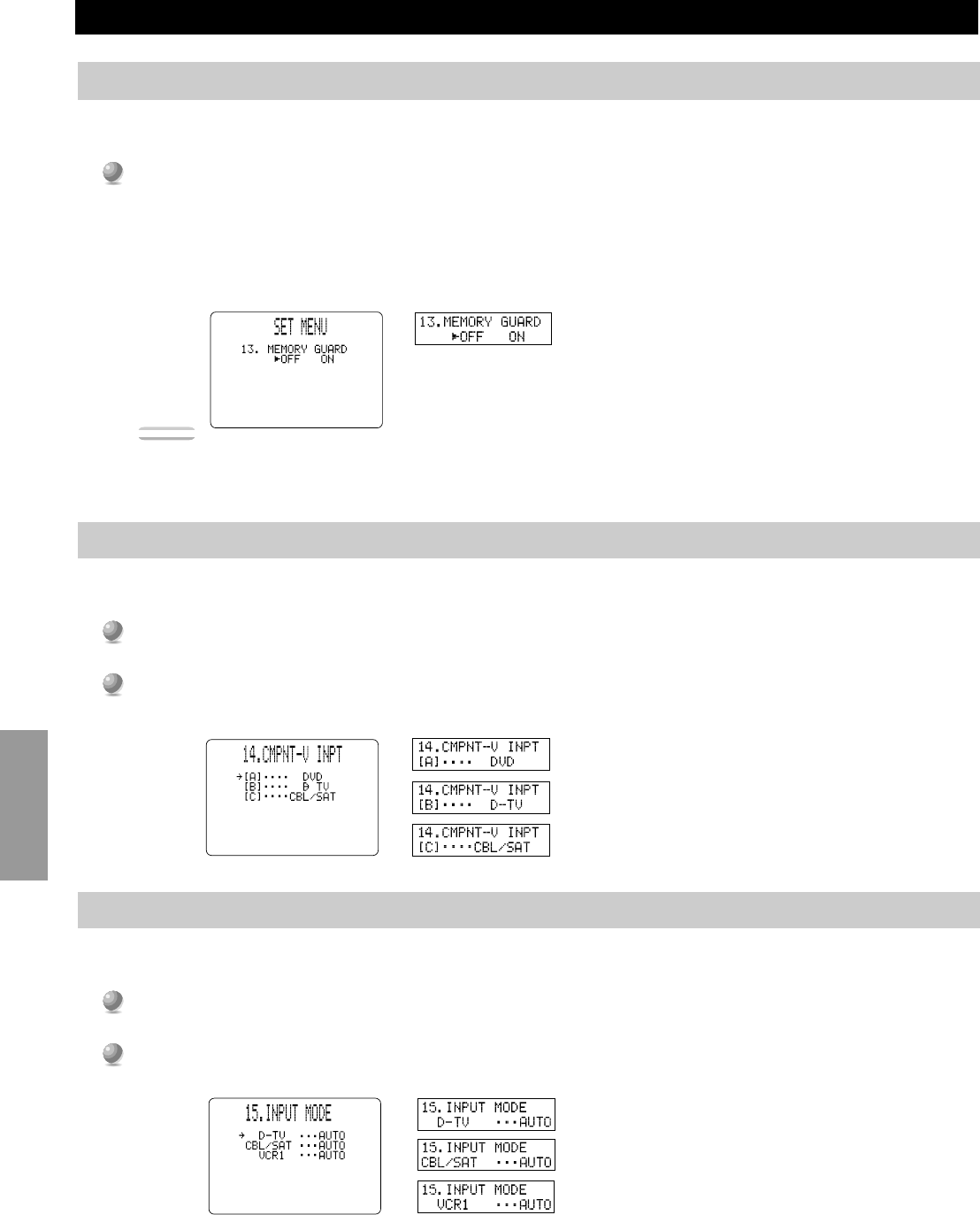
Selects the equipment to be connected to the component video inputs A, B or C.
Selects the initial input mode of the sources connected to D-TV, CBL/SAT and
VCR 1.
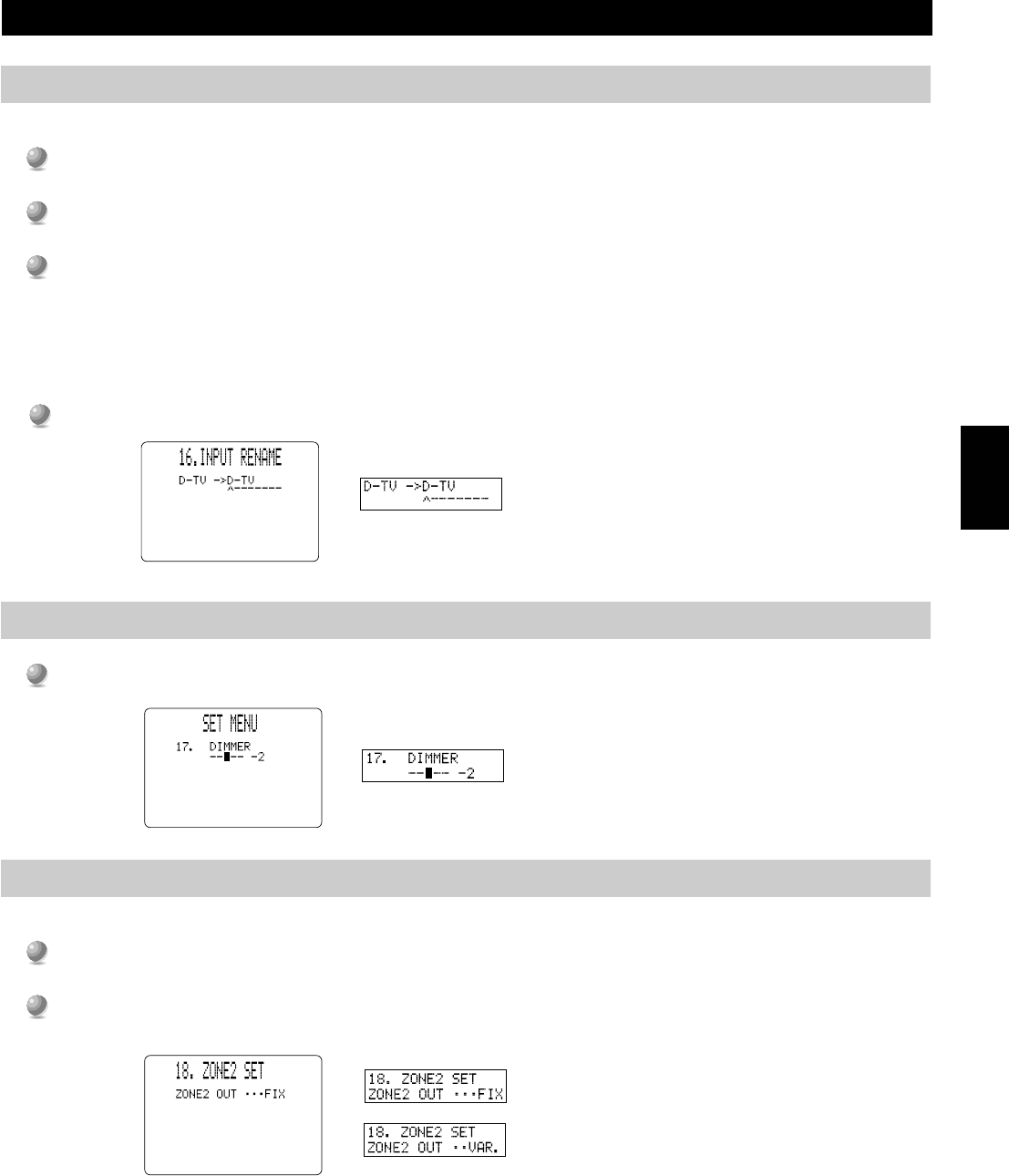
Changes the name of the inputs.
Adjusts the brightness of the front panel display.
Selects the mode of Zone 2.
Setting (Bold as default)
LRG / SML / NONE
LARGE / SMALL
LRG / SML / NONE
LRG / SML / NONE
SW / MAIN / BOTH
YES / NONE
Normal / –10 dB
TEST TONE: OFF / ON
OUTPUT: MAIN L/R, MAIN L, CENTER,
MAIN R, R SUR.(REAR R), REAR CT,
L SUR.(REAR L), SUBWOOFER, FRONT
FREQ.: 35 Hz-250 Hz
SPEAKER: –20 dB to 0 dB
HEADPHONE: –20 dB to 0 dB
SP(SPEAKER): MAX / STD / MIN
HP(HEADPHONE): MAX / STD / MIN
SPEAKER: –10 dB to +10 dB (0 dB)
HEADPHONE: –10 dB to +10 dB (0 dB)
CENTER: 0 ms to 5 ms
REAR CNTR: 0 ms to 30 ms (3 ms)
0 ms to 99 ms
5-band: –6 dB to +6 dB (0 dB)
5-band: –6 dB to +6 dB (0 dB)
LCR, FRNT EFCT, REAR L/R, REAR CT: OFF /
ON
HIGH-
FRQ: 1 kHz to 12.7 kHz
GAIN: – 9 dB to +6 dB (–3 dB or 0 dB)
PEQ-
FRQ: 1 kHz to 12.7 kHz (8 kHz or 12.7 kHz)
GAIN: –9 dB to +6 dB (–3 dB or –4 dB)
BASS, TRBL : –6 dB to +3 dB (0 dB)
1 to 12
ON / OFF
OFF / ON
A: DVD
B: D-TV
C: CBL/SAT
D-TV: AUTO / LAST
CBL/SAT: AUTO / LAST
VCR1: AUTO / LAST
Up to eight characters.
–4 to 0
ZONE 2 OUT: FIX(fixed) / VAR.(variable)
SET MENU Items
The SET MENU consists of eighteen items including the Speaker Set, Center Graphic Equalizer and Parameter Initialization features.
Choose the appropriate item and adjust or select the values as necessary.
Notes:
•You can adjust the items in the SET MENU while reproducing a source.
•We recommend that you adjust the items in the SET MENU while using a video monitor. It is easier to see the video monitor screen than it is to see the
front panel display on this unit while adjusting SET MENU items.
Page
39
39
39
40
40
41
41
42
43
44
44
44
45
45
46
47
47
47
48
48
48
49
49
49
38
Advanced
Operation
SET MENU Items
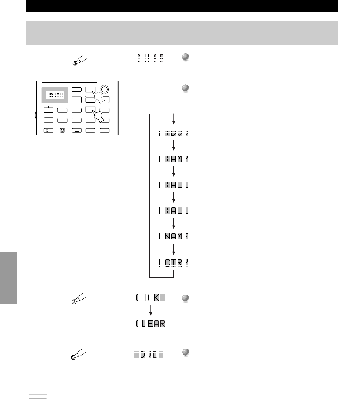
■General procedure for adjusting items
Some items require extra steps to change to the desired setting.
1
1
Set PARAMETER/SET MENU to SET MENU.
2
2
Press
%
or
%
(or NEXT) repeatedly to select an item, then press + or – (or SET MENU + or –) to change the setting
of that item.
•The last item you adjusted appears on the front panel display (or in the SET MENU OSD if you are using a video monitor).
•If “Press + / – Key!” appears on the display, press + or – (or SET MENU + or – ) to select an item, press
%
or
%
(or NEXT) to
select a sub item, and then press + or – (or SET MENU + or – ) to change the setting of that item.
3
3
Press
%
or
%
(or NEXT) repeatedly or a DSP program button to exit the SET MENU.
Note:
•NEXT on the main unit works the same as
%
on the remote control. It does not work as
%
.
ON SCREEN
LEVEL
SLEEPTEST
PARAMETER
SET MENU
%
%
PARAMETER
SET MENU
PHONESBASSTREBLE
NATURAL SOUND AV AMPLIFIER
DSP-AX1
INPUT MODE
POWER
INPUT SELECTOR
VOLUME
S VIDEOVIDEOLRAUDIO
VIDEO AUX
CINEMA DSP
DOLBY
DIGITAL
DIGITAL
SURROUND
ONOFF
55
44
33
22
11
0
+
–
55
44
33
22
11
0
+
–
55
44
33
22
11
0
RL
VCR 2CD
VCR 1
TUNER
CBL/SATTAPE
D-TV
MD
LD
DVD
BALANCE
PHONOVCR 3
VIDEO AUX
REC OUT/ZONE 2
SOURCE/REMOTE
BASS
EXTENSION
PROCESSOR
DIRECT
STANDBY/ON
6CH IMPUT
SET MENU
–
+
NEXT
EFFECT
PROGRAM
SPEAKERS
AB
+
–
#@
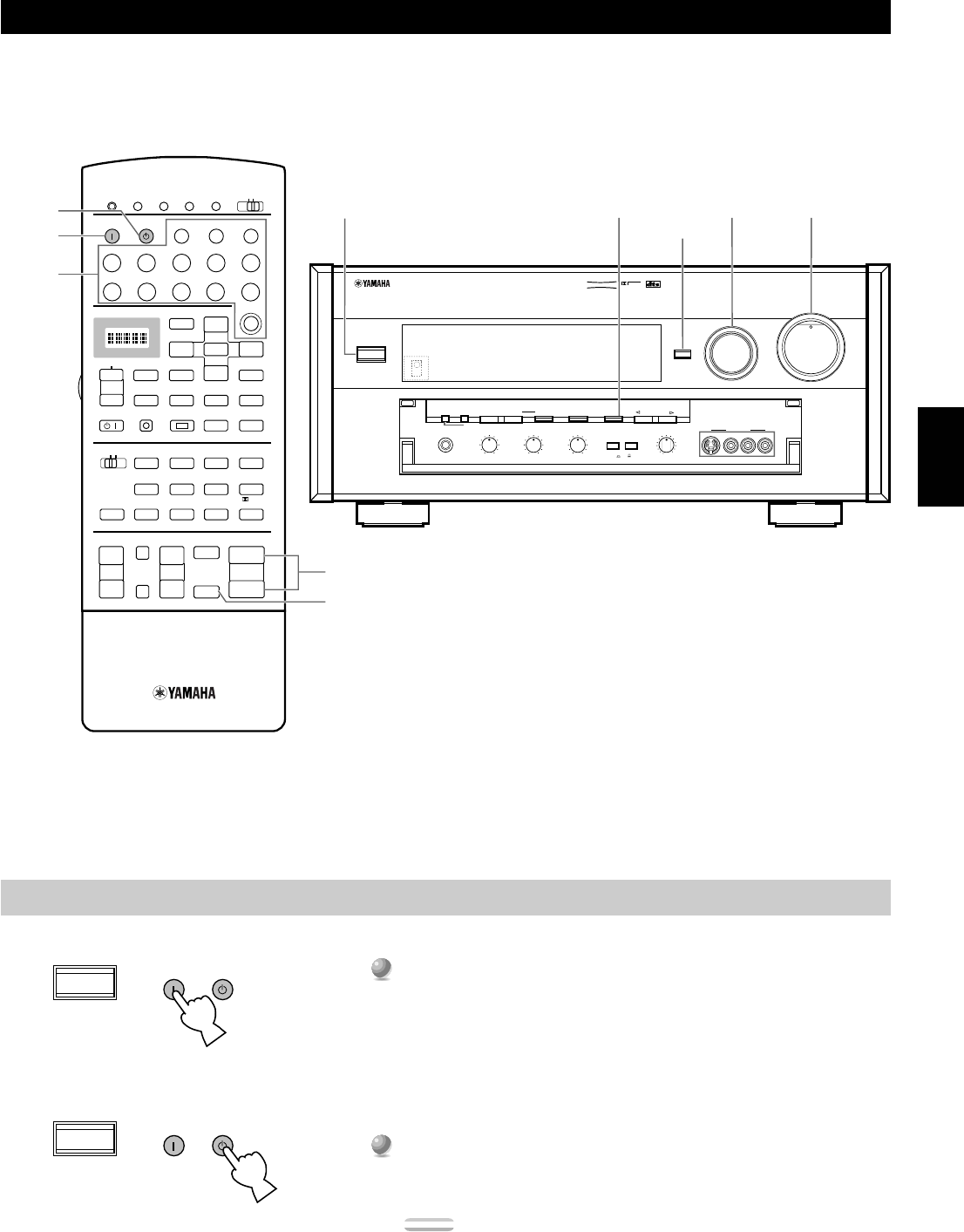
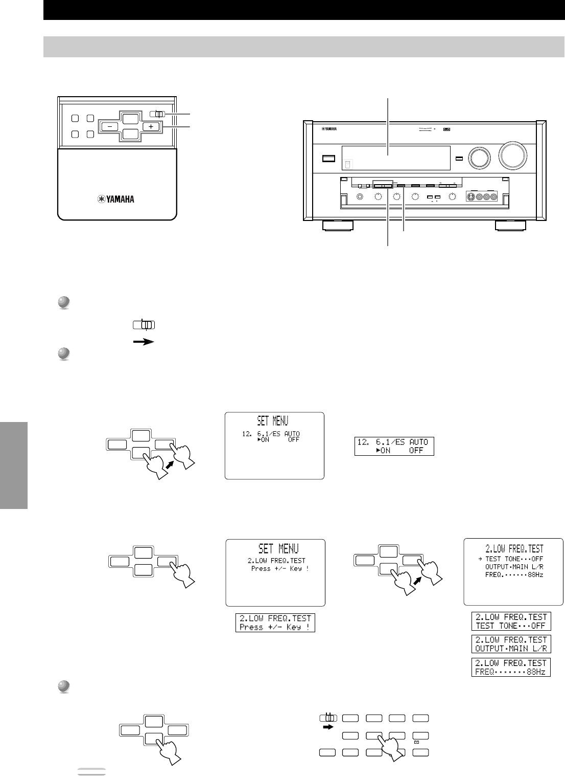
Operating the SET MENU
This section describes how to adjust items in the SET MENU using the remote control. To make adjustments using the controls on the main
unit, use the buttons referred to in parentheses.
+
–
#@
10KEYDSPHALL 1HALL 2CHURCHJAZZ CLUB
ROCK
CONCERT
ENTER-
TAINMENT
CONCERT
VIDEO 2
CONCERT
VIDEO 1
6.1/ES
TV
THEATER
MOVIE
THEATER 2
MOVIE
THEATER 1
/DTS
SUR.
0+10+100
1234
5678
9101112
CHP/INDEX
+
–
#@
+
–
#@
PARAMETER / SET MENU
Cursor buttons
Front Panel Display
Front Panel Display
OSD (On Screen Display)
SET MENU –/+
NEXT
or
39
English
SET MENU Items
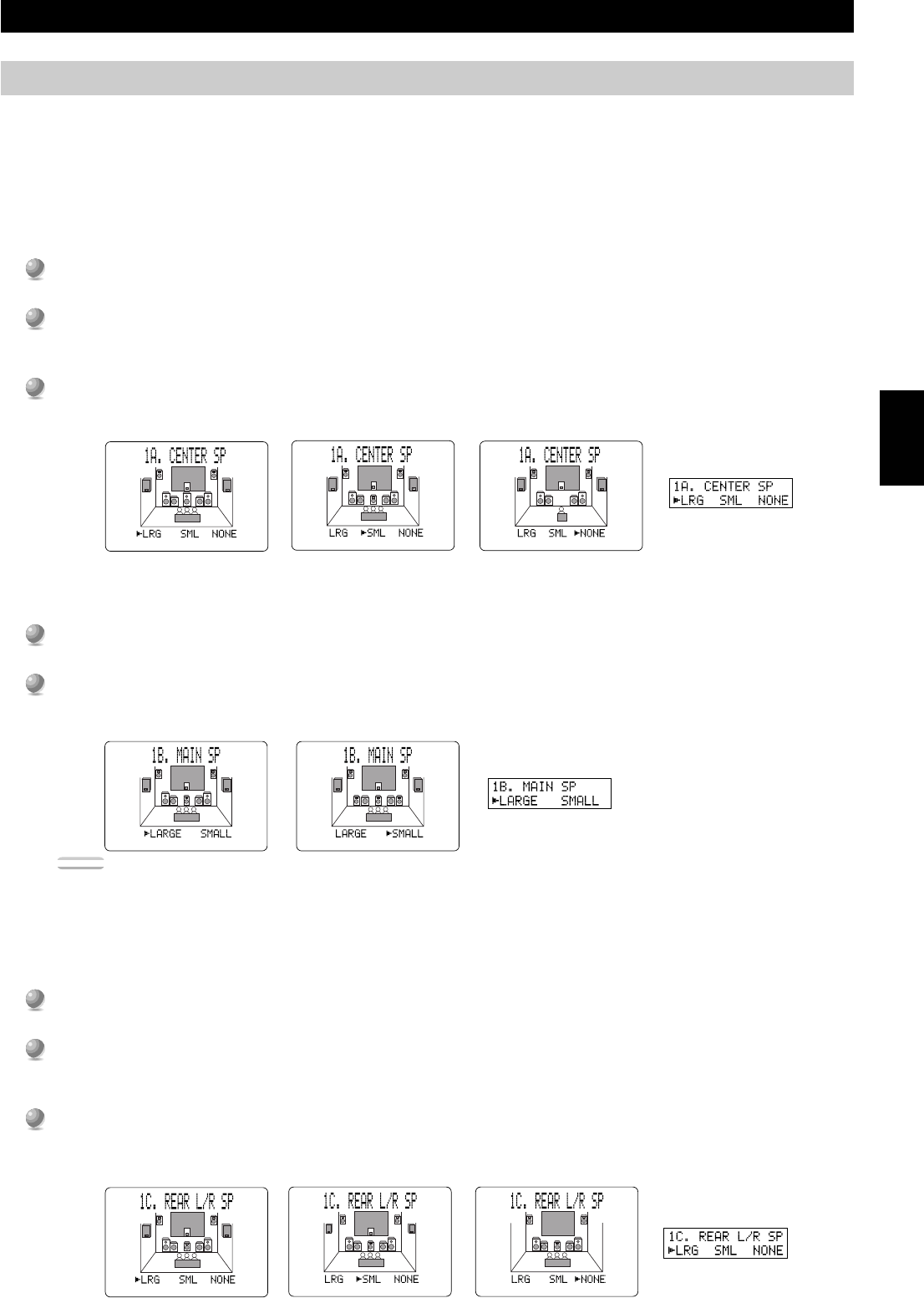
Use this feature to select suitable output modes for your speaker configuration. You must set the output mode when you use a subwoofer.
■1A. CENTER SP (Center Speaker Mode)
By adding a Center speaker to your speaker configuration, the DSP-AX1 can provide good dialogue localization for many listeners and
superior synchronization of sound and images. The OSD shows a large, small or no center speaker depending on how you set this item.
The initial setting is “LRG”.
Select the “LRG” (Large) setting if you have a large Center speaker. The entire range of Center channel signals is sent
to the Center speaker.
Select the “SML” (Small) setting if you have a small Center speaker. Center channel low frequency signals of 90 Hz
and below are directed to the speakers selected with the 1E. LFE/BASS OUT item (see page 40).
Select the “NONE” setting if you do not have a Center speaker. All of the Center channel signals are directed to the
left and right Main speakers. The “NONE” position provides good dialogue localization for the person sitting in the
main listening position.
■1B. MAIN SP (Main Speaker Mode)
The display shows small or large Main speakers depending on how you set this item. The initial setting is “LARGE”.
Select the “LARGE” setting if you have large Main speakers. The entire range of left and right Main channel signals is
directed to the left and right Main speakers.
Select the “SMALL” setting if you have small Main speakers. The Main channel low frequency signals of 90 Hz and
below are directed to the speakers selected with the 1E. LFE/BASS OUT item (see page 40).
Note:
•When you select the “MAIN” setting for the 1E. LFE/BASS OUT item, the Main channel low frequency signals of 90 Hz and below are directed
to the Main speakers even if you select the “SMALL” setting for the Main speaker mode. In this case, the OSD shows large Main speakers.
■1C. REAR L/R SP (Rear Speaker Mode)
The OSD shows large, small or no Rear speakers depending on how you set this item. The initial setting is “LRG”.
Select the “LRG” setting if you have large left and right Rear speakers or if you use a Rear Subwoofer (see page 22).
The entire range of Rear channel signals is sent to the left and right Rear speakers.
Select the “SML” setting if you have small left and right Rear speakers. Rear channel low frequency signals of 90Hz
and below are directed to the speakers selected with the 1E. LFE/BASS OUT item (see page 40).
Select the “NONE” setting if you do not have Rear speakers.
• In this case, Rear Center speaker will automatically be set to “NONE” and the 1D. REAR CT SP item will be skipped.
NoneSmall
Large
LargeSmall
LargeSmall
None
1. SPEAKER SET (1A. CENTER SP to 1G. MAIN LEVEL)
40
Advanced
Operation
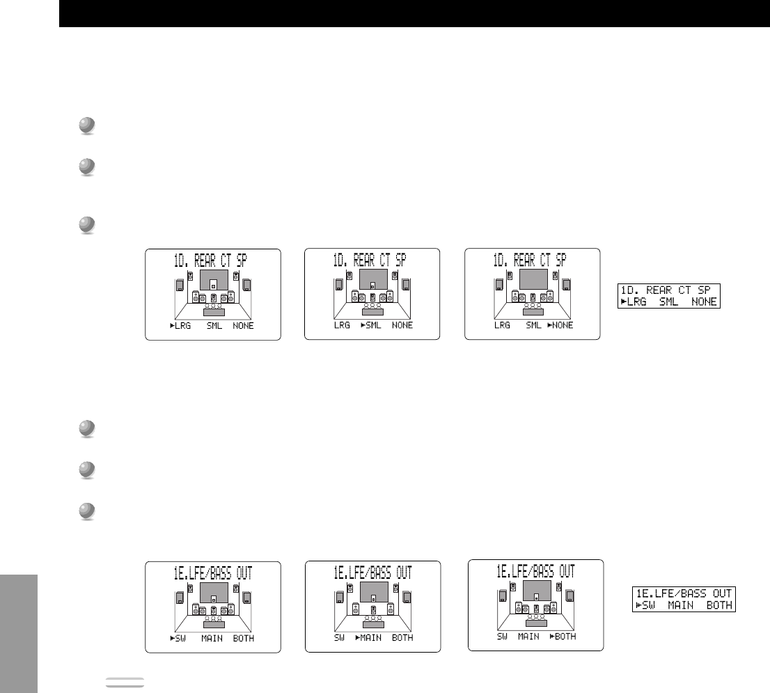
■1D. REAR CT SP (Rear Center Speaker Mode)
By adding a Rear Center speaker to your speaker configuration, the DSP-AX1 can provide more realistic front-to-back and back-to-front
transitions. The initial setting is “LRG”.
Select the “LRG” setting if you have a large Rear Center speaker. The entire range of Rear Center channel signals is
sent to the Rear Center speakers.
Select the “SML” (small) setting if you have a small Rear Center speaker. Rear Center channel low frequency signals
of 90 Hz and below are distributed to speakers selected with the 1E. LFE/BASS OUT item.
Select the “NONE” setting if you do not have a Rear Center speaker.
■1E. LFE/BASS OUT (Bass Out Mode)
LFE signals carry low frequency effects when this unit decodes DTS or Dolby Digital signals. Low frequency signals are defined as 90
Hz and below. The initial setting is “BOTH”.
Select the “SW” (Subwoofer) setting if you use a Subwoofer. The LFE signals are directed to the Subwoofer.
Select the “MAIN” setting if you do not use a Subwoofer. The LFE signals are directed to the Main speakers.
Select the “BOTH” setting if you use a Subwoofer and you want to mix the Main channel low frequency sound signals
with the LFE signals.
Note:
•The low frequency signals of 90Hz and below from all Main, Center, Rear and Rear Center channels are directed to the LFE channel when you
select the small speaker setting in items 1A, 1B, 1C and 1D.
SET MENU Items
Large
Small
None
Subwoofer
Main
Both
41
English
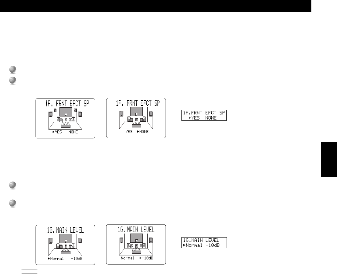
■1F. FRNT EFCT SP (Front Effect Speaker Mode)
The DSP-AX1 uses Front Effect speakers to localize the virtual sound sources of the sound field programs. If you do not use Front Effect
speakers, you can direct the Front Effect signals to the Main speakers.
The OSD shows small or no Front Effect speakers depending on how you set this item. The initial setting is “YES”.
Select the “YES” setting if you use Front Effect speakers.
Select the “NONE” setting if you do not use Front Effect speakers. The Front Effect signals are mixed with the Main
channels.
■1G. MAIN LEVEL
Change this setting if you cannot match the sound volume of the Front, Rear, and Center speakers with the Main speakers because of the
unusually high efficiency performance of the Main speakers. The initial setting is “Normal”.
Select the “Normal” setting if you can match the volume of your effect speakers with the volume of your Main
speakers using the Dolby Surround Test (page 28).
Select the “–10dB” setting if you cannot match the volume of your effect speakers with the volume of your Main
speakers using the Dolby Surround Test (page 28).
Note:
•When this unit decodes 96 kHz sampling/24 bit digital signals or 6CH INPUT is on, level adjustments in items 1A~1F are not possible.
SET MENU Items
YES
NONE
Normal
–10dB
42
Advanced
Operation
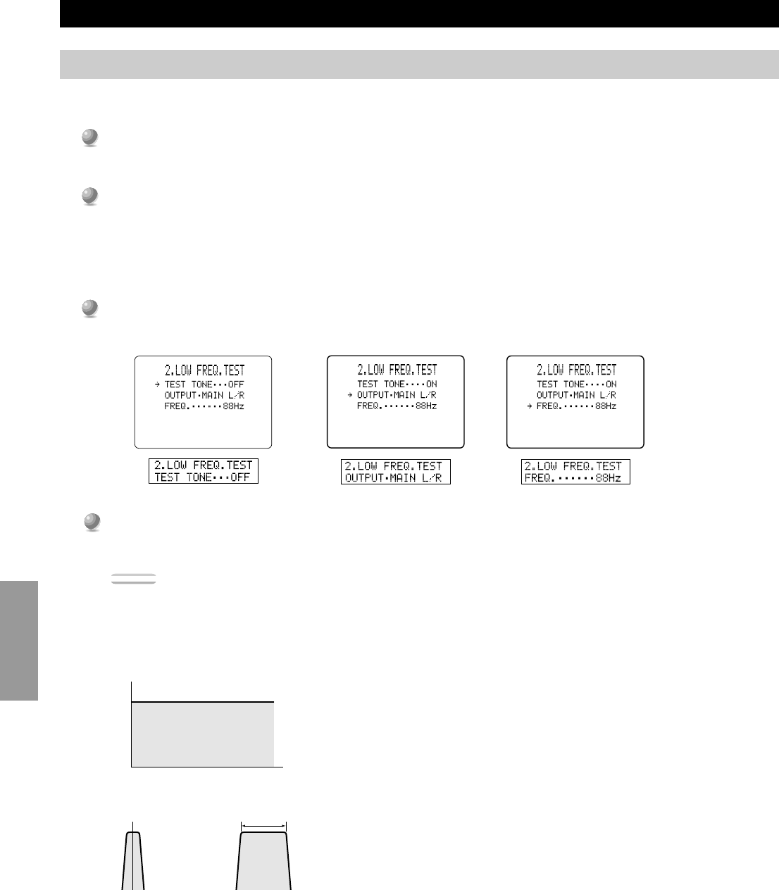
SET MENU Items
Use this feature to adjust the Subwoofer volume so it matches the volume of the other speakers in your configuration. Change the setting
using the remote control while sitting in the main listening position.
1
1
Press + or – (or SET MENU + or –) to set TEST TONE to “ON”, and adjust the volume using VOLUME + (or
VOLUME) so you can hear the tone.
2
2
Press
%
(or NEXT) repeatedly to go to OUTPUT and press + or – (or SET MENU + or –) to select the speaker you
want to compare with the Subwoofer.
•If “SUBWOOFER” is selected, test tones above 90 Hz will not be output from the Subwoofer. The test tone will not necessarily
be output from the selected speakers. The output mode of the test tone depends on the settings of the 1. SPEAKER SET items in
the SET MENU.
3
3
Press
%
(or NEXT) repeatedly to go to FREQ. and press + or – (or SET MENU + or –) to select the frequency you
want to use.
4
4
Adjust the Subwoofer volume using the controls on the Subwoofer so it matches the volume of the speaker you are
comparing it to.
Notes:
• Do not turn up the VOLUME too high.
• If no test tone is heard, turn off the power and make sure all the necessary hookups are correct.
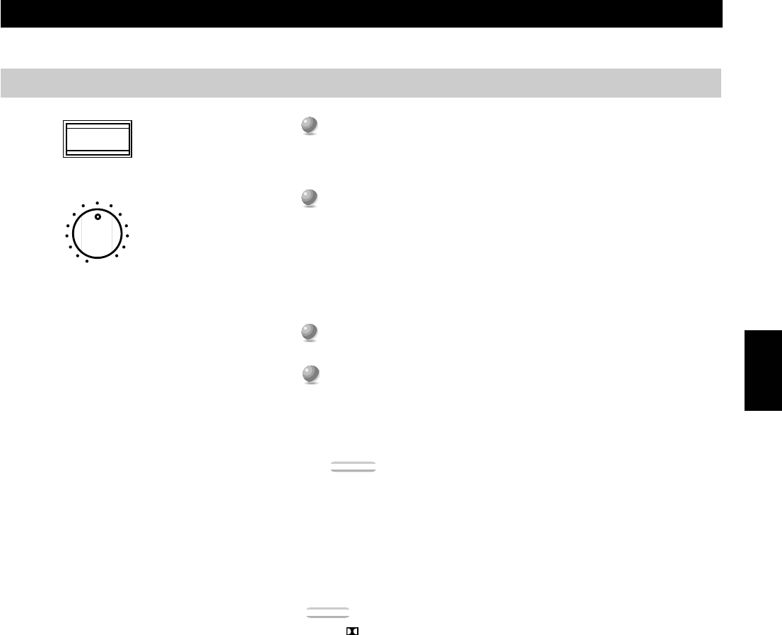
■About the Test Tone
The test tone is produced by the tone generator.
The tone generator produces a narrow band noise centered at a specified
frequency by the band pass filter.
You can change the center frequency from 35 Hz through 250 Hz in one-sixth
octave steps.
You can use the test tone not only for adjusting the subwoofer level, but also for
checking the low frequency characteristics of your listening room. Low frequency
sounds are especially affected by the listener’s position, speaker placement,
subwoofer polarity and other conditions.
Digital Generator
(Wide Band Noise Produced)
Band Pass Filter
2. LOW FREQ. TEST
Center freq.35 Hz~250 Hz
NOISE
FREQ.
43
English
SET MENU Items
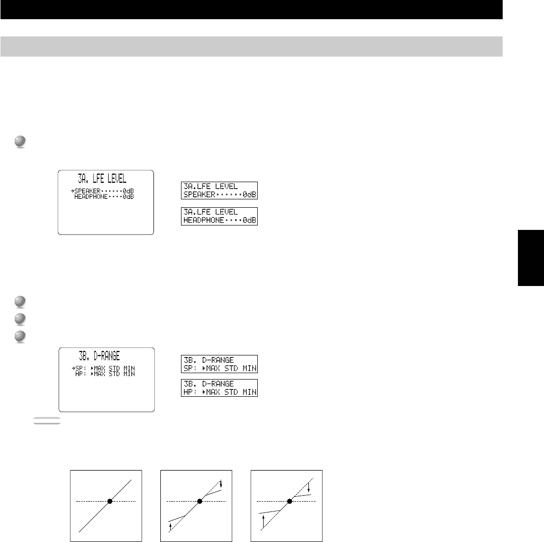
■3A. LFE LEVEL
Use this feature to adjust the output level of the LFE (low frequency effect) channel when playing back Dolby Digital encoded software.
This setting is effective only when this unit decodes Dolby Digital signals. The LFE signal carries the low frequency special effect sound
which is only added to certain scenes.
You can adjust the levels from 0 dB to –20 dB.
•Adjust the LFE levels according to the capacity of your subwoofer or headphones.
■3B. D-RANGE (Dynamic Range)
Use this feature to adjust the dynamic range. This setting is effective only when this unit decodes Dolby Digital signals.
Select the “MAX” setting for feature films.
Select the “STD” (Standard) setting for general use.
Select the “MIN” setting for listening to sources at extremely low volume levels.
Note:
•When D-RANGE is set to “MIN”, sound output may be faint because some Dolby Digital software is not compatible with the minimum level
dynamic range.
L-LEVEL BST
H-LEVEL CUT
0.0
0.0
1.0
1.0
Dialogue
level
Dialogue
level
Dialogue
level
MAXSTD
MIN
Output Level
Output Level
Output Level
Input Level
Input LevelInput Level
3. DOLBY D. SET (Dolby Digital Set)
Dialogue
level
Dialogue
level
Dialogue
level
44
Advanced
Operation
SET MENU Items
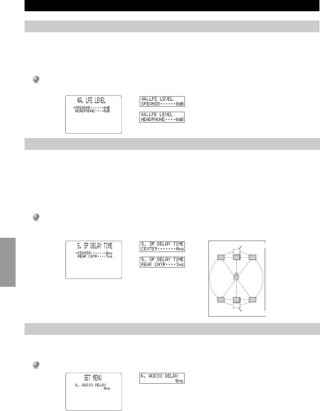
■4A. LFE LEVEL
Use this feature to adjust the output level of the LFE (low frequency effect) channel when playing back DTS encoded software. This
setting is effective only when this unit decodes DTS signals. The LFE signal carries the low frequency special effect sound which is only
added to certain scenes.
You can adjust the levels from –10 dB to +10 dB.
•Adjust the LFE level according to the capacity of your subwoofer or headphones.
5. SP DELAY TIME
Use this feature to adjust the delay of the Center and the Rear Center channel sounds. This feature works when this unit decodes DTS or
Dolby Digital signals. Ideally, the Center speaker and the Rear Center speaker should be the same distance from the main listening position
as the left and right Main speakers. However, in most home situations, the Center speaker or the Rear Center speaker is placed in line with
the Main speakers or the Rear speakers. By delaying the sound from the Center speaker and the Rear Center speaker, the apparent distance
from the Center speaker and the Rear Center speaker to the main listening position can be adjusted to make it seem the same as the distance
between the left and right Main speaker, and the left and right Rear speakers to the listening position. Adjusting the delay time for the Center
speaker is especially important for giving depth to the dialogue.
You can adjust the delay time from 0 ms to 5 ms for the Center speaker and from 0 ms to 30 ms for the Rear Center
speaker.
•Increasing the delay 1 ms simulates moving the speakers about 30 cm (one foot) farther away from the listening position.
6. AUDIO DELAY
Use this feature to adjust the delay time of all channel sounds, when this unit decodes DTS or Dolby Digital signals. Adjusting AUDIO
DELAY is especially important for matching the sounds to screen pictures. Initial settings is “0ms”.
You can adjust the delay time from 0ms to 99ms.
L
C
C
R
RL
RC
RC
RR
4. DTS SET
Rear Center speaker image
Center speaker image
45
English
SET MENU Items
7. CENTER GEQ (Center Graphic Equalizer)
Use this feature to adjust the built-in five band graphic equalizer so the Center speaker tone matches that of the left and right Main speakers.
You can select the 100 Hz, 300 Hz, 1 kHz, 3 kHz, or 10 kHz frequencies.
1
1
Use
%
to select a higher frequency and
%
to select a lower frequency.
2
2
Press + or – (or SET MENU + or –) to adjust the level of that frequency.
Note:
•You can monitor the Center speaker sound while adjusting this item using the Dolby Surround test tone generator. Press TEST before starting the
procedure above. “TEST DOLBY SUR.” appears, and the test tone starts alternating among the speakers. Once you begin the procedure above,
the test tone remains at the Center speaker and you can hear how the sound changes as you adjust the various frequency levels. To turn off the test
tone generator, press TEST repeatedly until the current DSP program appears (see page 28).
8. REAR CT GEQ (Rear Center Graphic Equalizer)
Use this feature to adjust the built-in five band graphic equalizer so the Rear Center speaker tone matches that of the left and right Main
speakers.
1
1
Use
%
to select a higher frequency and
%
to select a lower frequency.
2
2
Press + or – (or SET MENU + or –) to adjust the level of the selected frequency.
46
Advanced
Operation
SET MENU Items
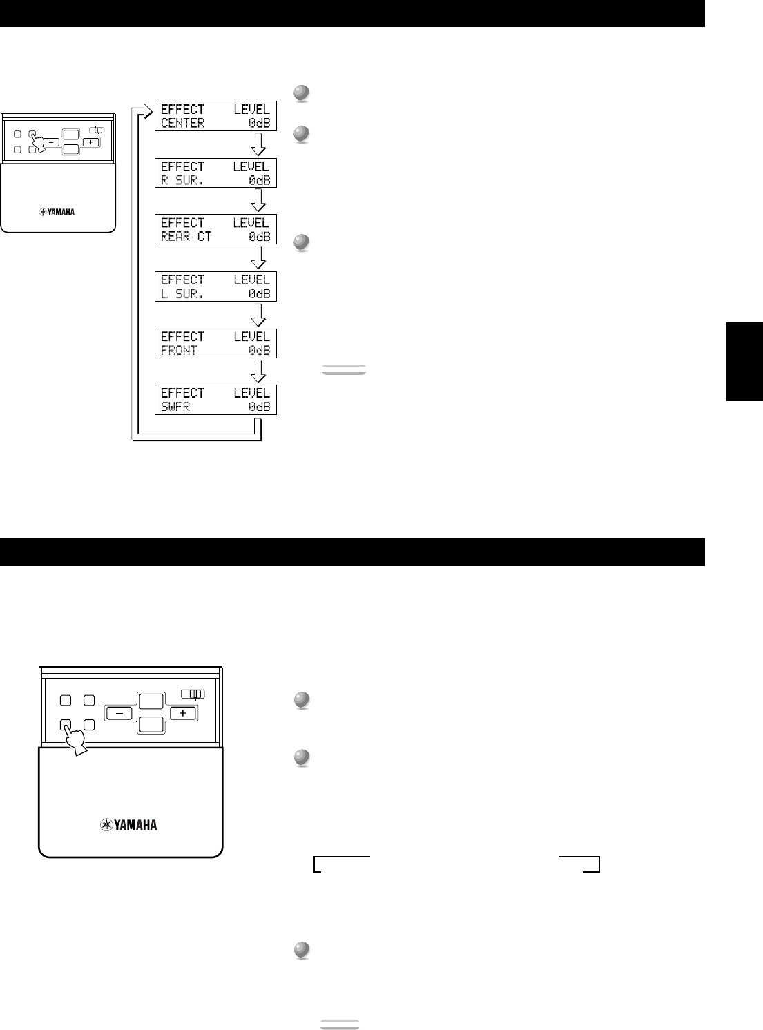
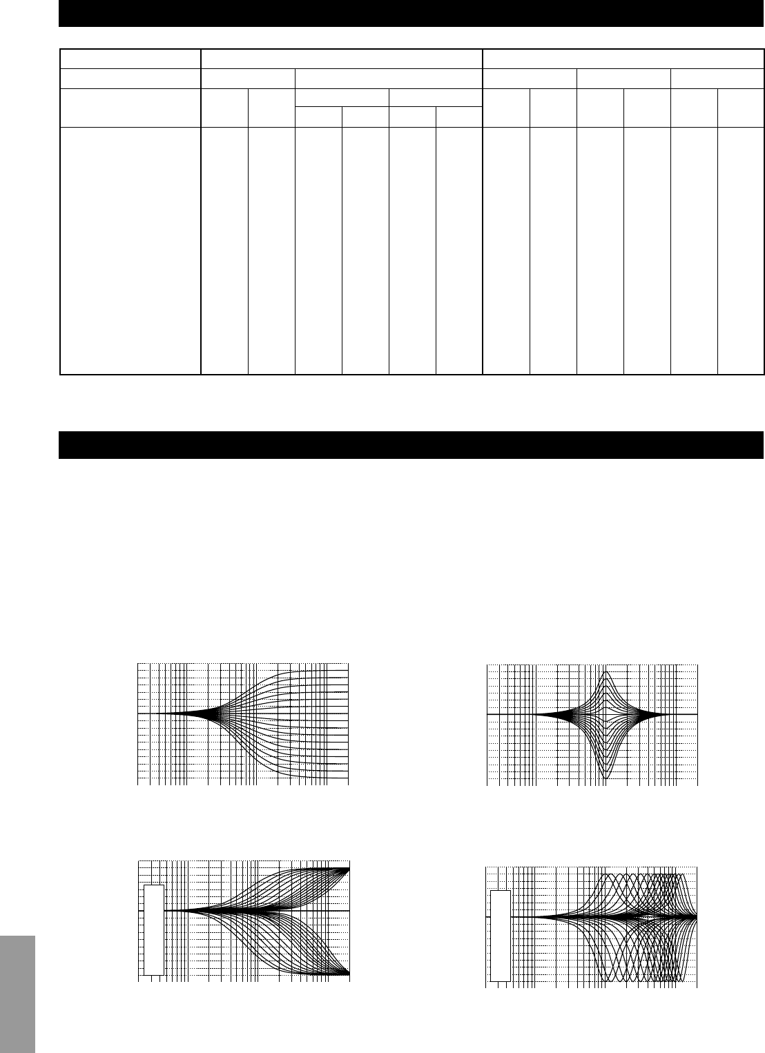
9. CINEMA EQ
Use this feature to match the tonal quality of four groups of speakers: the Main and Center speaker group, the Front Effect speakers group,
the Rear speakers group, and the Rear Center speaker group. CINEMA-EQ consists of a high-shelving equalizer (HIGH) and a parametric
equalizer (PEQ). The high-shelving equalizer changes high frequency characteristics, and the parametric equalizer boosts or cuts any selected
frequency. The equalizer can be used for a variety of purposes, such as adjusting the tonal quality of differing types of speakers, adjusting the
tonal quality in different installation environments, or adjusting the source sound to your liking.
The CINEMA EQ characteristic charts below show the value of the CINEMA EQ factory settings for each speaker group for general
listening conditions.
If you want to change the characteristics, follow the procedure below to adjust the frequency and gain for the high-shelving equalizer (HIGH)
and parametric equalizer (PEQ). For the more detailed characteristics in different settings, see “CINEMA-EQ Frequency Characteristics” on
page 82.
1
1
Press
%
or
%
(or NEXT) repeatedly to select one of the speaker groups and press + (or SET MENU +) to select
“ON”.
2
2
Press
%
or
%
(or NEXT) repeatedly to select one of the following parameters, then press + or – (or SET MENU + or
–) to change the setting of that parameter.
•Each time you press
%
(or NEXT ), the parameter changes on the front panel display as shown above. Press the cursor
%
to go
in the reverse order.
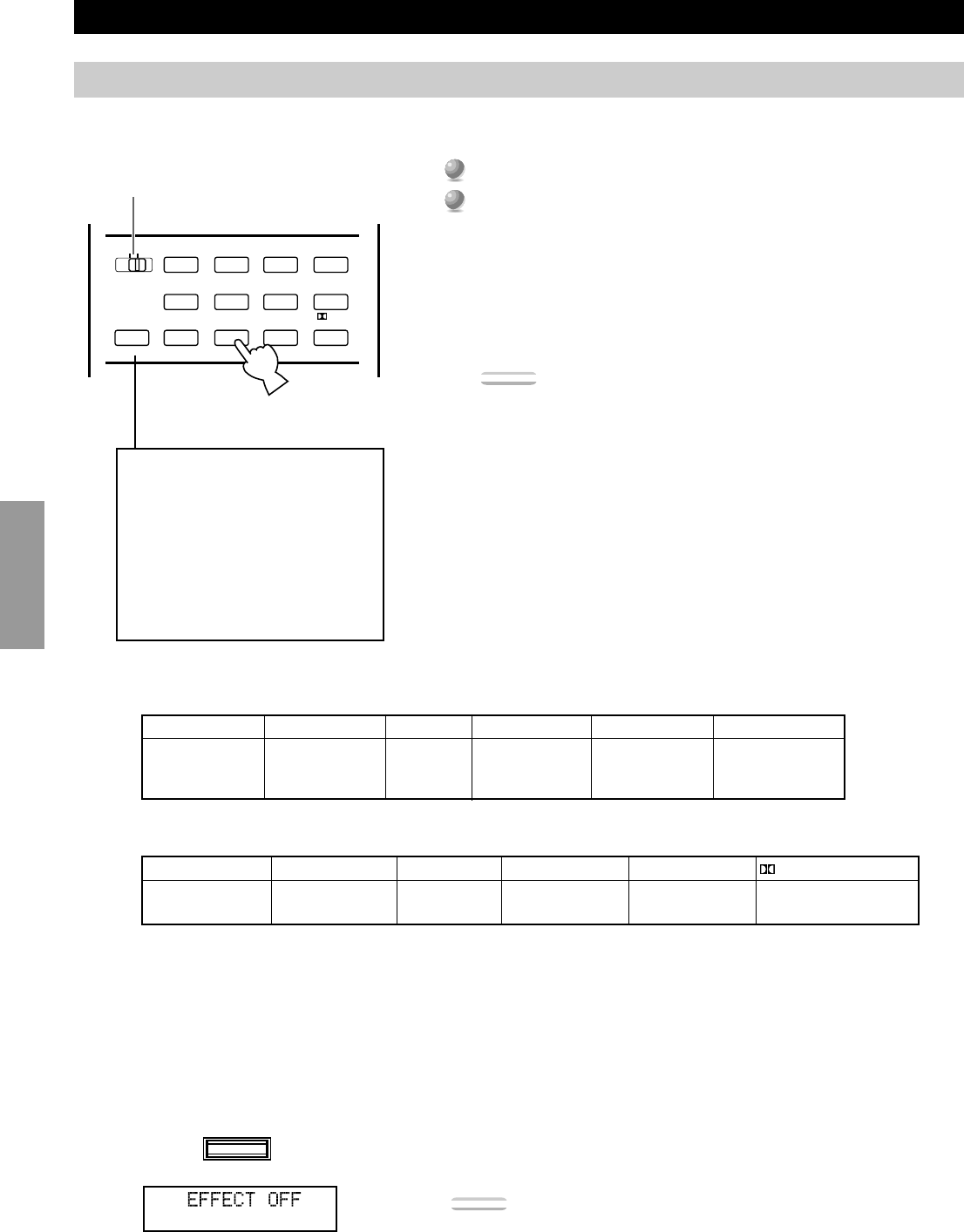
Notes:
•When the 1F. FRNT EFCT SP item is set to “NONE”, the Front Effect signals are output from the Main speakers.
•CINEMA-EQ does not work when you press EFFECT to turn off the effect.
▲L.C.R. Preset Value
HIGH:FRQ 12.7 kHzGAIN –3 dB
PEQ:FRQ 12.7 kHzGAIN –4 dB
PEQ
HIGH
HIGH
+
PEQ
G
A
I
N
FRQ
▲FRONT and REAR Preset Value
HIGH:FRQ12.7 kHzGAIN 0dB
PEQ:FRQ8.0 kHzGAIN –3dB
+6
+3
0
–3
–6
–9
20501002005001k2k5k10k20k
PEQ
HIGH
G
A
I
N
FRQ
47
English
SET MENU Items
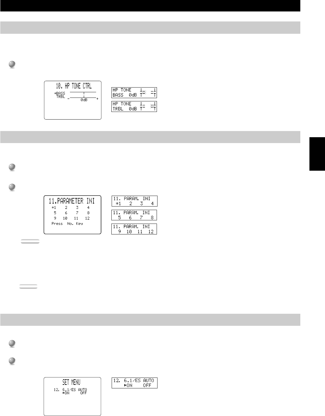
10. HP TONE CTRL (Headphone Tone Control)
Use this feature to adjust the level of bass and treble when you use your headphones. The initial Setting is 0 dB for both bass and treble.
This does not effect to the 96 kHz sampling digital signal.
Select BASS or TRBL and press + or – to change each level. You can adjust the level from –6 dB to +3 dB.
11. PARAMETER INI (Parameter Initialization)
Use this feature to initialize the parameters for each DSP program within a DSP program group. When you initialize a DSP program group,
all of the parameter values within that group revert to their initial settings.
Press the DSP program group button on the remote control for the DSP program you want to initialize.
•All of the DSP programs within the selected program group are initialized.
Repeat this step to initialize other DSP program groups.
Notes:
•The asterisk (*) mark next to a DSP program group number indicates that you have changed the parameter values in one or more DSP programs
within that group.
•The parameter values of the DSP programs do not change if you initialize a program group that does not have the asterisk (*) mark.
•When the MEMORY GUARD function is set to “ON” (see page 48), you cannot initialize any program groups.
•You cannot initialize the individual DSP programs within a group separately.
Caution:
•Once you initialize a DSP program group, you cannot have this unit revert the parameter values back to the previous settings automatically.
12. 6.1/ES AUTO
Use this feature to switch the DOLBY Digital Matrix 6.1 and DTS ES AUTO mode on or off.
Select “ON” to allow the main unit to automatically turn on the Dolby Digital Matrix 6.1 or DTS ES decoder when the
software with identification signal is detected.
Select “OFF” if you want to control the mode manually by pressing 6.1/ES on the remote.
48
Advanced
Operation
SET MENU Items
13. MEMORY GUARD
Use this feature to prevent accidental changes to DSP program parameter values and other settings on this unit.
Select “ON” to use MEMORY GUARD to protect the following features:
•DSP program parameters
•All SET MENU items
•Front, Rear, Center speaker and Subwoofer levels
•The On-Screen Display mode
Notes:
•When MEMORY GUARD is “ON”, you cannot use any of the test modes.
•When MEMORY GUARD is “ON”, you cannot select any other SET MENU item.
14. CMPNT-V INPUT (Component Video Input)
Use this feature to designate the input for each COMPONENT VIDEO terminal, A, B, and C. The initial settings are as written on the rear
panel. (Terminal A is for DVD, terminal B is for D-TV, and terminal C is for CBL/SAT.)
1
1
Select [A], [B], or [C] according to which terminal your equipment is connected to by pressing
%
or
%
.
2
2
Select the video input for your equipment by pressing + or –.
• You cannot select the same input once you have already selected it.
15. INPUT MODE
Use this feature to designate the input mode for sources connected to D-TV, CBL/SAT and VCR 1 input jacks when you turn on this unit.
Select “AUTO” to allow this unit to automatically detect the type of input signal and select the appropriate input
mode.
Select “LAST” to set this unit to automatically select the last input mode used for that source.
49
English
SET MENU Items
16. INPUT RENAME
Use this feature to change the name of the input which appears on the OSD or the front panel display.
1
1
Select the input you want to change the name of by pressing an input button (or using INPUT SELECTOR).
2
2
Press + or – to place the
^
under the space or the character you want to edit.
3
3
Press
%
or
%
to select the character you want to use and + or – to move to the next one.
• Press
%
to change the character in the following order, or press
%
to go in the reverse order.
A~Z, a space, 0~9, a space, a~z, a space, #, *, +, and so on.
• Follow the procedure above to rename other inputs.
4
4
Press + or – repeatedly to exit the INPUT RENAME mode.
17. DIMMER
You can adjust the brightness of the front panel display from –4 to 0.
18. ZONE 2 SET
Use this feature to change the volume control setting for audio output to ZONE 2.
Selecting “VAR.” allows you to control the volume output to ZONE 2 with the remote control.
Select “FIX” when you don’t want to change the volume output to ZONE 2 with the remote control.
50
Advanced
Operation
Remote Control Features
The remote control can operate the main unit as well as other Yamaha audio and video components. To control the components of other
manufacturers (or some Yamaha), you must set up the remote control with the manufacturer’s codes. This remote control also has a
sophisticated Learn feature that allows it to acquire functions from the remote controls of other components in your system (or other
household appliances) equipped with infrared remote control receivers. The Macro feature allows you to program a series of operations in
sequence onto a single button, or use the factory preset macros to operate other Yamaha components. These features make it possible for you
to reduce the number of remote control units in your entertainment room.
Notes:
•For operating distance of the remote control and notes about batteries, refer to page 5.
•For the name and function of each part and button, refer to pages 8 and 9.
•If the memory in the remote control becomes full, no further learning is possible even if there are still some programmable buttons available.
Using the Remote Control
<Main Unit Control Area>
The main unit control area is the shaded area shown below. It is
for controlling the DSP-AX1. You can use functions within this
area no matter which Component Control Area is selected.
<Component Control Area>
The component control area is the shaded area shown below. Each
component has different functions for operation buttons in the
component control area. The component, which was chosen by
pressing an input button, can be controlled and the display
window shows the corresponding name of the input.
TRANSMITRE-NAMECLEAR
MACRO
MACROLEARN
OFFON
SYSTEM
POWER
STANDBY
V-AUXTAPEPHONO
D-TVCBL/SATTUNERMDCD
VCR 1VCR 2VCR 3LDDVD
6CH INPUT
TITLE
ENTER
MENU
SOUND
DISPLAY
SOURCE
SELECT
SEARCHCHAPTER
%
!
!
$
*#
$
%
%
%
%
%
10KEYDSPHALL 1HALL 2CHURCHJAZZ CLUB
ROCK
CONCERT
ENTER-
TAINMENT
CONCERT
VIDEO 2
CONCERT
VIDEO 1
POWERRECSTOPPAUSEPLAY
EX/ES
TV
THEATER
MOVIE
THEATER 2
MOVIE
THEATER 1
0+10+100
1234
5678
9101112
+++
TV-VOL
A / B / C / D / EPRESET
TV INPUT
TV MUTE
CH
DISC
MUTE
EFFECT
VOLUME
+–
/
CHP/INDEX
–––
TITLE
ENTER
MENU
SOUND
DISPLAY
SEARCHCHAPTER
%
!
!
$
*#
$
%
%
%
10KEYDSPHALL 1HALL 2CHURCHJAZZ CLUB
ROCK
CONCERT
ENTER-
TAINMENT
CONCERT
VIDEO 2
CONCERT
VIDEO 1
POWERRECSTOPPAUSEPLAY
EX/ES
TV
THEATER
MOVIE
THEATER 2
MOVIE
THEATER 1
0+10+100
1234
5678
9101112
++
TV-VOL
A / B / C / D / EPRESET
TV INPUT
TV MUTE
CH
DISC
+–
/
CHP/INDEX
––
TITLE
ENTER
MENU
SOUND
DISPLAY
SEARCHCHAPTER
%
!
!
$
*#
$
%
%
%
10KEYDSPHALL 1HALL 2CHURCHJAZZ CLUB
ROCK
CONCERT
ENTER-
TAINMENT
CONCERT
VIDEO 2
CONCERT
VIDEO 1
POWERRECSTOPPAUSEPLAY
6.1/ES
TV
THEATER
MOVIE
THEATER 2
MOVIE
THEATER 1
0+10+100
1234
5678
9101112
++
TV VOL
A / B / C / D / EPRESET
TV INPUT
TV MUTE
CH
DISC
+–
/
CHP/INDEX
––
ON SCREEN
LEVEL
SLEEPTEST
PARAMETER
SET MENU
%
%
TRANSMITRE-NAMECLEAR
MACRO
MACROLEARN
OFFON
SYSTEM
POWER
STANDBY
V-AUXTAPEPHONO
D-TVCBL/SATTUNERMDCD
VCR 1VCR 2VCR 3LDDVD
6CH INPUT
TITLE
ENTER
MENU
SOUND
DISPLAY
SOURCE
SELECT
SEARCHCHAPTER
%
!
!
$
*#
$
%
%
%
%
%
10KEYDSPHALL 1HALL 2CHURCHJAZZ CLUB
ROCK
CONCERT
ENTER-
TAINMENT
CONCERT
VIDEO 2
CONCERT
VIDEO 1
POWERRECSTOPPAUSEPLAY
6.1/ES
TV
THEATER
MOVIE
THEATER 2
MOVIE
THEATER 1
0+10+100
1234
5678
9101112
+++
TV VOL
A / B / C / D / E
PRESET
TV INPUT
TV MUTE
CH
DISC
MUTE
EFFECT
VOLUME
+–
/
CHP/INDEX
–––
Input selector
10KEY/DSP
(DSP is selected)
Input selector
and switching
the control area
for each
component
10KEY/DSP
(10KEY is selected)
There are 14 component control areas. You can setup the manufacturer code and
program other remote control functions in each area (Cannot setup the
manufacturer code in the OPTN area). See pages 57 and 58.
51
English
Remote Control Features
■SOURCE SELECT
You can control another component independently from the input you selected by pressing an input button.
1
1
Press SELECT
%
or
%
to choose a component and set the remote control to be used for it.
2
2
The display windowwill show one of the following: V-AUX, TAPE, PHONO, D-TV (digital and regular TV),
When you make up a second audio-video room with this unit’s Zone2 system, you might want to use this remote control. Selecting
Zone2 sets the remote control to be in the Zone2 mode. See page 65 for details.
■About OPTN
OPTN is an extra component control area to be programmed with other remote control functions. (You cannot setup the manufacturer
code in this area.) See page 56 for the programmable area.
■Light up function
The buttons which are active and the display window light up for 10 seconds after pressing LIGHT.
SOURCE
SELECT
%
%
6CH INPUT
TITLE
ENTER
MENU
SOUND
DISPLAY
SOURCE
SELECT
SEARCHCHAPTER
%
!
!
$
*#
$
%
%
%
%
%
POWERRECSTOPPAUSEPLAY
+–
/
6CH INPUT
TITLE
ENTER
MENU
SOUND
DISPLAY
SOURCE
SELECT
SEARCHCHAPTER
%
!
!
$
*#
$
%
%
%
%
%
POWERRECSTOPPAUSEPLAY
+–
/
TRANSMITRE-NAMECLEAR
MACRO
MACROLEARN
OFFON
SYSTEM
POWER
STANDBY
V-AUXTAPEPHONO
D-TVCBL/SATTUNERMDCD
VCR 1VCR 2VCR 3LDDVD
6CH INPUT
TITLE
ENTER
MENU
SOUND
DISPLAY
SOURCE
SELECT
SEARCHCHAPTER
%
!
!
$
*#
$
%
%
%
%
%
10KEYDSPHALL 1HALL 2CHURCHJAZZ CLUB
POWERRECSTOPPAUSEPLAY
1234
+–
/
Pressing % selects Zone2 first.
Pressing fi selects OPTN first.
52
Advanced
Operation
Remote Control Features
Each Component Control Area
The general operational buttons are shown for each area. Some of them may not function depending on the equipment you have.
■Operating a Tuner (TUNER Area)
■Operating a Tape Deck (TAPE Area)
SYSTEM
POWER
STANDBY
V-AUXTAPEPHONO
D-TVCBL/SATTUNERMDCD
VCR 1VCR 2VCR 3LDDVD
6CH INPUT
TITLE
ENTER
MENU
SOUND
DISPLAY
SOURCE
SELECT
SEARCHCHAPTER
%
!
!
$
*#
$
%
%
%
%
%
10KEYDSPHALL 1HALL 2CHURCHJAZZ CLUB
ROCK
CONCERT
ENTER-
TAINMENT
CONCERT
VIDEO 2
CONCERT
VIDEO 1
POWERRECSTOPPAUSEPLAY
6.1/ES
TV
THEATER
MOVIE
THEATER 2
MOVIE
THEATER 1
0+10+100
1234
5678
9101112
+++
TV VOL
A / B / C / D / EPRESET
TV INPUT
TV MUTE
CH
DISC
MUTE
EFFECT
VOLUME
+–
/
CHP/INDEX
–––
POWER
Preset numbers 1 to 8
Preset group A/B/C/D/E
Fast forward
Rewind
REC/PAUSE
TV VOL +/–, TV INPUT, and TV
MUTE function if you have set up
the manufacturer code for the D-
TV Area.
Deck A / Deck B
Direction A / B
PRESET + / –
PLAY
STOP
53
English
Remote Control Features
■Operating a CD Player (CD Area)
■Operating an MD Recorder (MD Area)
SYSTEM
POWER
STANDBY
V-AUXTAPEPHONO
D-TVCBL/SATTUNERMDCD
VCR 1VCR 2VCR 3LDDVD
6CH INPUT
TITLE
ENTER
MENU
SOUND
DISPLAY
SOURCE
SELECT
SEARCHCHAPTER
%
!
!
$
*#
$
%
%
%
%
%
10KEYDSPHALL 1HALL 2CHURCHJAZZ CLUB
ROCK
CONCERT
ENTER-
TAINMENT
CONCERT
VIDEO 2
CONCERT
VIDEO 1
POWERRECSTOPPAUSEPLAY
6.1/ES
TV
THEATER
MOVIE
THEATER 2
MOVIE
THEATER 1
0+10+100
1234
5678
9101112
++
+
TV VOL
A / B / C / D / E
PRESET
TV INPUT
TV MUTE
CH
DISC
MUTE
EFFECT
VOLUME
+–
/
CHP/INDEX
–––
SYSTEM
POWER
STANDBY
V-AUXTAPEPHONO
D-TVCBL/SATTUNERMDCD
VCR 1VCR 2VCR 3LDDVD
6CH INPUT
TITLE
ENTER
MENU
SOUND
DISPLAY
SOURCE
SELECT
SEARCHCHAPTER
%
!
!
$
*#
$
%
%
%
%
%
10KEYDSPHALL 1HALL 2CHURCHJAZZ CLUB
ROCK
CONCERT
ENTER-
TAINMENT
CONCERT
VIDEO 2
CONCERT
VIDEO 1
POWERRECSTOPPAUSEPLAY
6.1/ES
TV
THEATER
MOVIE
THEATER 2
MOVIE
THEATER 1
0+10+100
1234
5678
9101112
+++
TV VOL
A / B / C / D / EPRESET
TV INPUT
TV MUTE
CH
DISC
MUTE
EFFECT
VOLUME
+–
/
CHP/INDEX
–––
TV VOL +/–, TV INPUT, and TV
MUTE function if you have set up
the manufacturer code for the D-
TV Area.
Skip Search
PAUSE (YAMAHA : Pause / Stop)
Numeric buttons 1 to 9
Numeric button +10
Numeric button 0
DISC +/– (Disc Skip)
TV VOL +/–, TV INPUT, and TV
MUTE function if you have set up
the manufacturer code for the D-
TV Area.
REC/PAUSE
Numeric buttons 1 to 9
Numeric button +10
Numeric button 0
Skip Search
DISPLAY
SEARCH
STOP
POWER
INDEX
PLAY
CLEAR
DISPLAY
SEARCH
POWER
PLAY
PAUSE
STOP
54
Advanced
Operation
Remote Control Features
■Operating an LD Player (LD Area)
■Operating a DVD Player (DVD Area)
SYSTEM
POWER
STANDBY
V-AUXTAPEPHONO
D-TVCBL/SATTUNERMDCD
VCR 1VCR 2VCR 3LDDVD
6CH INPUT
TITLE
ENTER
MENU
SOUND
DISPLAY
SOURCE
SELECT
SEARCHCHAPTER
%
!
!
$
*#
$
%
%
%
%
%
10KEYDSPHALL 1HALL 2CHURCHJAZZ CLUB
ROCK
CONCERT
ENTER-
TAINMENT
CONCERT
VIDEO 2
CONCERT
VIDEO 1
POWERRECSTOPPAUSEPLAY
6.1/ES
TV
THEATER
MOVIE
THEATER 2
MOVIE
THEATER 1
0+10+100
1234
5678
9101112
+++
TV VOL
A / B / C / D / E
PRESET
TV INPUT
TV MUTE
CH
DISC
MUTE
EFFECT
VOLUME
+–
/
CHP/INDEX
–––
SYSTEM
POWER
STANDBY
V-AUXTAPEPHONO
D-TVCBL/SATTUNERMDCD
VCR 1VCR 2VCR 3LDDVD
6CH INPUT
TITLE
ENTER
MENU
SOUND
DISPLAY
SOURCE
SELECT
SEARCHCHAPTER
%
!
!
$
*#
$
%
%
%
%
%
10KEYDSPHALL 1HALL 2CHURCHJAZZ CLUB
ROCK
CONCERT
ENTER-
TAINMENT
CONCERT
VIDEO 2
CONCERT
VIDEO 1
POWERRECSTOPPAUSEPLAY
6.1/ES
TV
THEATER
MOVIE
THEATER 2
MOVIE
THEATER 1
0+10+100
1234
5678
9101112
+++
TV VOL
A / B / C / D / E
PRESET
TV INPUT
TV MUTE
CH
DISC
MUTE
EFFECT
VOLUME
+–
/
CHP/INDEX
–––
TV VOL +/–, TV INPUT, and TV
MUTE function if you have set up
the manufacturer code for the D-
TV Area.
Chapter / Time
CHAPTER +/– (Chapter Search)
Numeric buttons 1 to 9
Numeric button +10
Numeric button 0
Numeric buttons 1 to 9
Numeric button +10
Numeric button 0
Return
Title / Index
TV VOL +/–, TV INPUT, and TV
MUTE function if you have set up
the manufacturer code for the D-
TV Area.
Skip Search
DISPLAY
SEARCH
POWER
STOP
SOUND
PLAY
PAUSE
CLEAR
TITLE
MENU
DISPLAY
SEARCH
POWER
Menu cursor / ENTER
SOUND
PLAY
PAUSE
STOP
CLEAR
Disc Skip
55
English
Remote Control Features
■Operating a VCR (VCR 1 / VCR 2 / VCR 3 Area)
■Operating a TV or Digital TV (D-TV Area)
SYSTEM
POWER
STANDBY
V-AUXTAPEPHONO
D-TVCBL/SATTUNERMDCD
VCR 1VCR 2VCR 3LDDVD
6CH INPUT
TITLE
ENTER
MENU
SOUND
DISPLAY
SOURCE
SELECT
SEARCHCHAPTER
%
!
!
$
*#
$
%
%
%
%
%
10KEYDSPHALL 1HALL 2CHURCHJAZZ CLUB
ROCK
CONCERT
ENTER-
TAINMENT
CONCERT
VIDEO 2
CONCERT
VIDEO 1
POWERRECSTOPPAUSEPLAY
6.1/ES
TV
THEATER
MOVIE
THEATER 2
MOVIE
THEATER 1
0+10+100
1234
5678
9101112
+++
TV VOL
A / B / C / D / EPRESET
TV INPUT
TV MUTE
CH
DISC
MUTE
EFFECT
VOLUME
+–
/
CHP/INDEX
–––
Rewind /
Fast Forward
TV VOL +/–, TV INPUT, and TV
MUTE function if you have set up
the manufacturer code for the D-
TV Area.
REC
(Press twice)
Numeric buttons 1 to 9
Numeric button 10 or 0
You can control your VCR,
if you have set up the code for VCR1.
Numeric buttons 1 to 9
Numeric button 10 or 0
Enter
POWER
TV / VIDEO
PLAY
PAUSE
STOP
CH +/–
DISPLAY
POWER
TV INPUT
TV VOL +/–
TV MUTE
CH +/–
56
Advanced
Operation
Remote Control Features
■Operating a Cable or Satellite TV Tuner (CBSAT Area)
■Free Area (OPTN and PHONO Areas)
6CH INPUT
TITLE
ENTER
MENU
SOUND
DISPLAY
SOURCE
SELECT
SEARCHCHAPTER
%
!
!
$
*#
$
%
%
%
%
%
10KEYDSPHALL 1HALL 2CHURCHJAZZ CLUB
ROCK
CONCERT
ENTER-
TAINMENT
CONCERT
VIDEO 2
CONCERT
VIDEO 1
POWERRECSTOPPAUSEPLAY
6.1/ES
TV
THEATER
MOVIE
THEATER 2
MOVIE
THEATER 1
0+10+100
1234
5678
9101112
+++
TV VOL
A / B / C / D / E
PRESET
TV INPUT
TV MUTE
CH
DISC
MUTE
EFFECT
VOLUME
+–
/
CHP/INDEX
–––
SYSTEM
POWER
STANDBY
V-AUXTAPEPHONO
D-TVCBL/SATTUNERMDCD
VCR 1VCR 2VCR 3LDDVD
6CH INPUT
TITLE
ENTER
MENU
SOUND
DISPLAY
SOURCE
SELECT
SEARCHCHAPTER
%
!
!
$
*#
$
%
%
%
%
%
10KEYDSPHALL 1HALL 2CHURCHJAZZ CLUB
ROCK
CONCERT
ENTER-
TAINMENT
CONCERT
VIDEO 2
CONCERT
VIDEO 1
POWERRECSTOPPAUSEPLAY
6.1/ES
TV
THEATER
MOVIE
THEATER 2
MOVIE
THEATER 1
0+10+100
1234
5678
9101112
+++
TV VOL
A / B / C / D / E
PRESET
TV INPUT
TV MUTE
CH
DISC
MUTE
EFFECT
VOLUME
+–
/
CHP/INDEX
–––
You can control your VCR,
if you have set up the code for VCR1.
Numeric buttons 1 to 9
Numeric button 0
Enter
Recall
Menu cursor / ENTER
TV VOL +/–, TV INPUT, and TV
MUTE function if you have set up
the manufacturer code for the D-
TV Area.
TV VOL +/–, TV
INPUT, and TV
MUTE function if you
have set up the
manufacturer code for
the D-TV Area.
DISPLAY
MENU
POWER
CH +/–
57
English
1
1
Select the source component you want to preset by using
the input buttons.
2
2
Press and hold LEARN for about three seconds using a
ballpoint pen or similar object.
3
3
Use
%
/
%
to select the name of your component’s
manufacturer.
•You will find the names of most audio-video manufacturers
worldwide in alphabetical order on the display window.
4
4
Press POWER (or any other button) on the remote control
while pointing it at the component to check if you have set
up the code correctly. If the component cannot be
controlled by the remote control, try entering another code
for the same manufacturer.
5
5
Press LEARN to confirm the preset.
•If you want to preset another code for another component
immediately, press ENTER and repeat steps 1 to 4.
1
1
Repeat steps 1 and 2 of the procedure in “Setting the
Manufacturer Code in the Remote Control”.
2
2
Select a Library (component category) by using
%
/
%
.
•There are 12 Libraries to set up a manufacturer code; L:TV,
L:CAB (CABLE), L:DBS, L:SAT, L:VCR, L:DVD, L:LD,
L:CD, L:MD, L:TAP (TAPE), L:TUN (TUNER), *L:AMP.
*L:AMP has three codes; YPC, DSP, and NO. “YPC” should be
selected to operate the DSP-AX1. “DSP” is for operating Yamaha
DSP amplifiers other than the DSP-AX1. “NO” is to clear the main
unit control area functions.
3
3
Repeat steps 3 and 4 of the procedure in “Setting the
Manufacturer Code in the Remote Control ”.
Remote Control Features
Setting the Manufacturer Code in the Remote Control
SYSTEM
POWER
STANDBY
V-AUXTAPEPHONO
D-TVCBL/SATTUNERMDCD
VCR 1VCR 2VCR 3LDDVD
LEARN
6CH INPUT
TITLE
ENTER
MENU
SOUND
DISPLAY
SOURCE
SELECT
SEARCHCHAPTER
POWERRECSTOPPAUSEPLAY
+–
/
%
!
!
$
*#
$
%
%
%
%
%
6CH INPUT
TITLE
ENTER
MENU
SOUND
DISPLAY
SOURCE
SELECT
SEARCHCHAPTER
%
!
!
$
*#
$
%
%
%
%
%
POWERRECSTOPPAUSEPLAY
+–
/
You can control other components by setting a manufacturer code. A code can be set up in each component controol area except for the
OPTN area. The Yamaha code is factory preset for DVD, LD, CD, MD, TUNER, and TAPE (Yamaha for LD, and Yamaha1 for others).
There is no factory preset code on VCR1/2/3, D-TV, CBSAT, V-AUX, and PHONO.
Note:
•If you have already programmed a remote control function to a button, the function takes priority over the set up manufacturer code’s function.
■Controlling a different component from the source component (input) you selected
Note:
•“ERROR” appears in the display window in the following conditions: when pressing a button other than the cursor and ENTER; when pressing more than
one button at once; and when one of MACRO ON/OFF, 10KEY/DSP, PARAMETER/SET MENU is switched to another position.
flashes alternately
58
Advanced
Operation
Remote Control Features
Programming a New Remote Control Function
If you desire to program functions not included in the basic operations covered by the manufacturer code, or a manufacturer code is not
available, the following procedure needs to be performed. The possible programming area is the same as a component control area, so
buttons are programmable independently for each source component area. It is also possible to program in the main unit control area.
(Refer to page 50 for details on component control area and main unit control area.)
1
1
Place this remote control and the other remote control
about 5 to 10 cm (2 to 4 in.) apart on a flat surface so that
their infrared transmitters are aimed at each other.
2
2
Select a source component.
3
3
Press LEARN using a ball point pen or similar object.
4
4
Press and release the button where you want the new
function to be programmed.
5
5
Press and hold the button on the other remote control that
has the function you want to program into this remote
control until “OK” appears in the display window.
•“NG” appears in display window when programming is not
done correctly.
6
6
Repeat Steps 4 and 5 to program additional functions.
7
7
Press LEARN again to exit the Learn mode.
LEARN
Notes:
•If you do not press any button within 30 seconds, the learning process is canceled.
•This remote control transmits infrared rays. If the other remote control also uses infrared rays, this remote control can learn most of the other remote
control’s functions. However, you may not be able to program some special signals or extremely long transmissions. (Refer to the operation instructions for
the other remote control.) When the memory is full, “FULL” appears in the display window, and this remote control cannot acquire any more functions.
Clear unnecessary programmed functions to allow the unit to acquire new functions.
•Even if the batteries in the other remote control have enough power to transmit signals for operation, they may not have enough power to transmit signals to
this remote control.
•When the remote controls are either too close together or too far apart, you may not be able to program this remote control.
•Direct sunlight interferes with infrared rays.
•“ERROR” appears in the display window in the following conditions: when pressing more than one button at once; and when MACRO ON/OFF is
switched to another position.
TRANSMITRE-NAMECLEAR
MACRO
MACROLEARN
OFFON
SYSTEM
POWER
STANDBY
V-AUXTAPEPHONO
D-TVCBL/SATTUNERMDCD
VCR 1VCR 2VCR 3LDDVD
6CH INPUT
TITLE
%
%
%
TAPE
A/B
TRANSMITRE-NAMECLEAR
MACRO
MACROLEARN
OFFON
SYSTEM
POWER
STANDBY
V-AUXTAPEPHONO
D-TVCBL/SATTUNERMDCD
VCR 1VCR 2VCR 3LDDVD
6CH INPUT
TITLE
%
%
%
LEARN
TRANSMITRE-NAMECLEAR
MACRO
MACROLEARN
OFFON
SYSTEM
POWER
STANDBY
V-AUXTAPEPHONO
D-TVCBL/SATTUNERMDCD
VCR 1VCR 2VCR 3LDDVD
6CH INPUT
TITLE
%
%
%
5~10 cm (2 to 4 in.)
flashes alternately
59
English
Using the Macro Feature
The Macro feature makes it possible to perform a series of operations by pressing just one button. For example, when you want to play a CD,
normally you would turn on the components, select the CD input, and press the play button to start playback. Using the Macro feature, you
can perform all those operations by simply pressing the CD macro button. The macro buttons (the input buttons and SYSTEM POWER
ON/STANDBY) are factory preset with macro programs. You can also program your own macros (see page 60).
Remote Control Features
Macro buttonFirstSecond
Third
TUNER
SYSTEM
POWER
STANDBY
TAPE
CBL/SAT
MD
VCR 1
VCR 2
VCR 3
LD
DVD
V-AUX
PHONO
D-TV
SYSTEM
POWER
STANDBY
TUNER
TAPE
CBL/SAT
MD
VCR 1
VCR 2
VCR 3
LD
DVD
V-AUX
PHONO
D-TV
POWER
/
#
PLAY
#
PLAY
#
PLAY
#
PLAY
#
PLAY
#
PLAY
#
PLAY
CD
Press a Macro buttonAutomatically transmits signals of each button sequentially
*1In order to turn on some Yamaha components connected to this unit, connect those components to AC OUTLETS on the rear panel.
*2If the macro you select includes power on/off functions, the equipment may turn off if it is already on when you press the macro button. For example, if
your TV is on and you press the SYSTEM POWER macro button, the TV turns off.
Note:
•Make sure you set up the manufacturer code (See page 57) or program a function using the Learn feature (See page 58) to the remote control for your
component, or the factory preset macros do not work.
(*1)
(*2)
(D-TV Area)
(TAPE Area)
(MD Area)
(LD Area)
(DVD Area)
(VCR1 Area)
(VCR2 Area)
(VCR3 Area)
SYSTEM
POWER
#
PLAY
CD
(CD Area)
60
Advanced
Operation
1
1
Press MACRO using a ball point pen or similar object.
•If you do not initiate the procedure within 30 seconds, the
macro programming process is canceled.
2
2
Press the macro button on which you want to program the
Macro.
• If you want to change the source component, use SOURCE
SELECT
%
/
%
or the input buttons. When you use input
buttons, input is selected as a Macro step, whereas SOURCE
SELECT
%
/
%
only changes the component.
•The display window shows the button you chose for
programming the macro and the component name in
alternation.
3
3
Press the buttons of the functions that you want to include
in the macro sequence in order.
•You can set up to 10 Macro steps (10 functions).
4
4
Press MACRO again when the sequence you want to
program is complete.
•After you set 10 steps, “FULL” is displayed.
1
1
Set MACRO ON/OFF to ON.
2
2
Press a Macro button.
Notes:
•When you are finished using the Macro feature, set MACRO ON/
OFF to OFF.
•While the main unit is carrying out a macro program, the main unit
does not receive any other button’s function until the macro is
complete (the TRANSMIT indicator stops flashing).
•Continue to aim the remote control at the equipment the macro is
operating until the macro program is complete.
MACRO
Remote Control Features
Notes:
•“NG” appears in the display window when programming is not done correctly.
•“ERROR” appears in the display window in the following conditions: when pressing more than one button at once; and when MACRO ON/OFF is
switched to another position.
MACRO
SYSTEM
POWER
STANDBY
V-AUXTAPEPHONO
D-TVCBL/SATTUNERMDCD
VCR 1VCR 2VCR 3LDDVD
6CH INPUT
TITLE
ENTER
MENU
SOUND
DISPLAY
SOURCE
SELECT
SEARCHCHAPTER
%
!
!
$
*#
$
%
%
%
%
%
POWERRECSTOPPAUSEPLAY
+–
/
1
2
3
SYSTEM
POWER
STANDBY
V-AUXTAPEPHONO
D-TVCBL/SATTUNERMDCD
VCR 1VCR 2VCR 3LDDVD
6CH INPUT
1
2
3
Macro buttons
flashes
alternately
indicates the number of
macrosteps you entered
flashes alternately
(ex)
MCR 1 : DVD input
MACRO ON/OFF
MCR 2 : DVD ›
MCR 3 : DVD #
■Operating the Macro Feature
■Programming a Macro
You can use the Macro feature to transmit many remote control commands by pressing a single button.
TRANSMITRE-NAMECLEAR
MACRO
MACROLEARN
OFFON
SYSTEM
POWER
STANDBY
V-AUXTAPEPHONO
D-TVCBL/SATTUNERMDCD
VCR 1VCR 2VCR 3LDDVD
6CH INPUT
TITLE
ENTER
%
%
%
61
English
Changing the Source Name in the Display Window
Remote Control Features
1
1
Select the source component you want to rename by using
the input buttons.
2
2
Press RE-NAME using a ballpoint pen or similar object.
3
3
Use the cursor buttons
%
/
%
to select a character.
•Pressing
%
changes the character in the following order:
A~Z, a~z, 0~9, space, -(hyphen).
4
4
Use the cursor buttons
%
/
%
to enter a character or more
to the next cursor postion.
5
5
Press RE-NAME to confirm renaming.
•If you want to rename another source component immediately,
press ENTER and repeat steps 1, 3 and 4.
1
1
Select the source component that you want to clear on the
window by using input buttons.
2
2
Press LEARN if you want to clear a learned function, or
press MACRO to clear a programmed macro, using a ball
point pen or similar object.
3
3
Press and hold CLEAR using a ball point pen or similar
object, and at the same time press the button from which
you want to clear the learned function or macro for about
3 seconds.
•“C:NG” appears in the display window if the operation is
unsuccessful. Should this occur, try doing step 3 again.
You can clear other learned functions and macros at this time by
continuing to hold down CLEAR and pressing the other buttons
on which those learned functions or macros are programmed.
4
4
Press LEARN again to confirm clearing a learned
function, or press MACRO again to confirm clearing a
programmed macro.
•Once you clear a learned function or macro from a button, the
button reverts to its factory preset function or macro.
Clearing a Learned Function or Macro
SYSTEM
POWER
STANDBY
V-AUXTAPEPHONO
D-TVCBL/SATTUNERMDCD
VCR 1VCR 2VCR 3LDDVD
CLEAR
MACRO
LEARN
SYSTEM
POWER
STANDBY
V-AUXTAPEPHONO
D-TVCBL/SATTUNERMDCD
VCR 1VCR 2VCR 3LDDVD
RE-NAME
SYSTEM
POWER
STANDBY
V-AUXTAPEPHONO
D-TVCBL/SATTUNERMDCD
VCR 1VCR 2VCR 3LDDVD
6CH INPUT
TITLE
ENTER
MENU
SOUND
DISPLAY
SOURCE
SELECT
SEARCHCHAPTER
%
!
!
$
*#
$
%
%
%
%
%
POWERRECSTOPPAUSEPLAY
+–
/
RE-NAME
MACRO
LEARN
or
flashes alternately
flashes
alternately
While pressing
62
Advanced
Operation
1
1
Press CLEAR using a ballpoint pen or similar object.
•If the remote control is without batteries for more than twenty minutes, or if worn out batteries remain in the unit, the contents of the memory may be
cleared.
When the memory is cleared, insert new batteries and program any acquired functions that may have been cleared.
•“ERROR” appears in the display window for the following conditions: when pressing a button other than the cursor and ENTER; when pressing more than
one button at once; and when one of MACRO ON/OFF, 10KEY/DSP, PARAMETER/SET MENU is switched to another position.
6CH INPUT
TITLE
ENTER
MENU
SOUND
DISPLAY
SOURCE
SELECT
SEARCHCHAPTER
%
!
!
$
*#
$
%
%
%
%
%
POWERRECSTOPPAUSEPLAY
+–
/
CLEAR
CLEAR
CLEAR
For example, when DVD is selected as
the source component.
3
3
Press and hold CLEAR again for about 3 seconds.
•“C:NG” appears in the display window if the operation is
unsuccessful.
4
4
Press CLEAR to confirm clearing.
•Once you clear a learned function or macro from a button, the
button reverts to its factory preset function or macro.
Clears all programmed functions
including manufacturer code presets.
This returns to the factory presets.
(L: name of a component) Clears all
learning functions of the component.
Clears all learning functions of the
main unit control area (see page 50).
Clears all learning functions.
Clears all macros.
Clears all renamed displays in the
display window.
63
English
Setting the Sleep Timer
Use this feature to automatically turn off the main unit after the amount of time you set. The Sleep Timer is useful when you plan to fall
asleep while the main unit is reproducing or recording a source. The Sleep Timer also automatically turns off external components connected
to AC OUTLETS. The Sleep Timer can only be set using the remote control.
■To set the Sleep Timer
1
1
Select a source using INPUT SELECTOR and start playback (or
select a broadcast station) on the source component.
2
2
Press SLEEP repeatedly to set the amount of time before the main
unit automatically turns off.
Each time you press SLEEP, the front panel display changes as shown
below. After a few seconds the display returns to the previous indication.
= SLEEP 120 min = SLEEP 90 min
SLEEP OFF + SLEEP 30 min + SLEEP 60 min+
■To cancel the Sleep Timer
1
1
Press SLEEP repeatedly until “SLEEP OFF” appears in the front
panel display.
After a few seconds, the display returns to the previous indication.
Note:
•The Sleep Timer setting can also be canceled by turning off the main unit using
STANDBY on the remote control (or STANDBY/ON on the front panel) or
disconnecting the AC Power Cord from the AC outlet.
ON SCREEN
LEVEL
SLEEPTEST
PARAMETER
SET MENU
%
%
Adjusting the Levels of the Effect Speakers
ON SCREEN
LEVEL
SLEEPTEST
PARAMETER
SET MENU
%
%
You can adjust the volume level of each effect speaker (Center, Right Rear, Rear Center, Left Rear, Front Effect, and Subwoofer) while
listening to a music source.
1
1
Set PARAMETER/SET MENU to PARAMETER.
2
2
Press LEVEL to select the speaker(s) you want to adjust.
Each time you press this button the selected speaker changes and appears in
the front panel display only as follows: Center, Right Rear, Rear Center, Left
Rear, Front Effect Speakers, and Subwoofer
3
3
Adjust the speaker volume level using the + or – on the remote
control.
You can adjust the Center, Right Rear, Rear Center, Left Rear, Front Effect
Speakers from +10 dB to –10 dB.
You can adjust the Subwoofer from 0 dB down to –20 dB.
Notes:
•You cannot adjust the left and right speakers independently.
•When you adjust the speaker level using LEVEL, the settings you made using the
Dolby Surround Test and DSP Test change.
•When PARAMETER/SET MENU is set to SET MENU, you cannot adjust the
speaker level using LEVEL. However, each time you press LEVEL the current
level setting of each speaker appears. Select the speaker level you want to check
using
%
or
%
.
Center
Right Rear
Rear Center
Left Rear
Front
Subwoofer
64
Advanced
Operation
ZONE 2
You can make up a multi-room audio-video system with this unit. With this feature, you can set this unit to reproduce separate input sources
in the main room and second (Zone 2) room using the supplied remote control in the second room.
ONLY ANALOG SIGNALS ARE SENT TO THE SECOND ROOM. FOR ANY SOURCE YOU WISH TO LISTEN
TO IN THE SECOND ROOM, YOU MUST CONNECT THE ANALOG OUTPUT FROM THE SOURCE TO THE
CORRESPONDING ANALOG INPUT ON THIS UNIT.
Connections
To use the multi-room functions of this unit, you need the following additional equipment:
•An infrared signal receiver in the second room
•An infrared emitter in the main room
This emitter transmits the infrared signals from the remote control in the second room to the main room
(for example, to a CD player or LD player).
•An amplifier and speakers for the second room
•A video monitor for the second room
Notes:
•Since there are so many ways to connect and use this unit in a multi-room installation,
we recommend that you consult with a custom installation specialist for the Zone 2
connections which will best meet your requirements.
•Some Yamaha models are able to connect directly to the REMOTE 1 OUT jacks of
this unit. If you own these products, you may not need to use an infrared emitter. Up to
six Yamaha components can be connected as shown.
■A sample of system configuration and connections
■Special considerations when using DTS software
The DTS signal is a digital bitstream. Therefore, if you attempt to send the DTS signal to Zone 2, you will only be able to hear the digital
noise that could damage your loudspeakers.
Due to this characteristic of DTS encoded discs, the following considerations and adjustments need to be made.
For DTS encoded LDs or DVDs
Only 2-channel audio signals may be sent to Zone 2, as follows:
•Laser disc – Set your Laser Disc player’s left and right outputs to the analog sound track.
•DVD disc – Use the disc menu to set the DVD player’s mixed 2-channel left and right audio outputs to PCM or Dolby Digital.
For DTS encoded compact discs
DO NOT USE the Zone 2 feature with DTS encoded compact discs.
OUTOUT
Remote 1
OUTININ
This Unit
Main Room
DVD Player
(or other component)
Infrared emitter
This Unit
Second Room
Amplifier
Video monitor
Remote control
(in the Zone 2 mode)
Infrared signal receiver
REMOTE 1 OUT
VIDEO SIGNAL ZONE 2 OUT
REMOTE 1 IN
AUDIO SIGNAL ZONE 2 OUT
65
English
Remote Control in ZONE 2
In the second (Zone 2) room, the supplied remote control can be used as the Zone 2 remote control. You can select the input source and
control the component which is located in the main room directly from the second room regardless of the listening condition in the main
room.
1
1
Press SOURCE SELECT
%
to display ZONE2 in the display
window.
2
2
Use the input buttons to select the input source you want to listen to.
•The display window shows “2: name of selected input” if the remote
control is in the Zone 2 mode.
3
3
You can control the component using the Component Control Area
buttons.
Note:
•VOLUME + / – can be used to adjust the volume if you set the SET MENU item
Le système d’enceinte le plus complet comprend 8 enceintes: enceintes principales gauche et droite, enceinte centrale, enceintes arrière
gauche et droite, enceintes avant gauche et droite chargées de la reproduction des effets sonores et enceinte centrale arrière. Si votre
installation ne comporte pas 8 enceintes, vous pouvez diriger vers les enceintes présentes les signaux qui étaient destinés aux enceintes
manquantes. Afin d’obtenir des sons plus riches, une enceinte d’extrêmes graves peut compléter chaque configuration proposée.
■Configuration à 7 ou 8 enceintes –Cinéma et DSP–
Cette configuration permet la reproduction fidèle et complète de tous les éléments
enregistrés sur la piste son des films en 70 mm. Les dialogues semblent provenir
de l’écran, les effets sonores d’un point légèrement en arrière de l’écran et la
musique d’une source qui serait encore plus loin derrière l’écran; tout cela permet
de restituer l’ampleur et la profondeur de la scène. Cette configuration tire tout le
parti possible des caractéristiques de l’appareil.
L’enceinte centrale arrière est utile pour la reproduction des signaux Dolby Digital
Surround EX, ou DTS ES.
■Configuration à 6 enceintes –Hi Fi et DSP–
Cette configuration est la plus utilisée pour la reproduction des enregistrements
haute fidélité auxquels sont ajoutées des corrections par processeur (DSP). Le
positionnement des dialogues est bon, bien qu’il ne soit pas aussi précis que dans
le cas de la configuration à 7 ou 8 enceintes. Toutefois, elle crée un champ sonore
dynamique grâce à l’intervention du processeur de signaux numériques (DSP) qui
apporte une grande profondeur aux sonorités. Pour définir cette configuration, les
paramètres 1A. CENTER SP et 1D. REAR CT SP de SET MENU doivent avoir la
valeur “NONE” (reportez-vous à la page 37).
■Configuration à 5 enceintes –Système standard à
5,1 voies–
Cette configuration n’exprime pas la puissance et la diversité sonores aussi bien
que la configuration à 7 ou 8 enceintes. Toutefois, elle positionne bien les
dialogues au niveau de l’écran.
Pour définir cette configuration, les paramètres 1F. FRONT EFCT SP et 1D.
REAR CT SP de SET MENU doivent avoir la valeur “NONE” (reportez-vous à la
page 37).
■Configuration à 4 enceintes –Configuration
minimale–
Dans ce cas, les signaux destinés à l’enceinte centrale et aux enceintes réservées
aux effets sonores, sont appliqués sur les enceintes principales gauche et droite.
Pour définir cette configuration, les paramètres 1A. CENTER SP, 1F. FRNT
EFCT SP et 1D. REAR CT SP de SET MENU doivent avoir la valeur “NONE”
(reportez-vous à la page 37).
Enceintes avant chargées de la
reproduction des effets sonores
Enceinte d’extrêmes
graves avant
Enceinte centrale
Enceintes principales
Enceintes arrière
Enceinte centrale arrière
Enceinte d’extrêmes graves arrière
14
Préparatifs
FL
L
RL
CR
FR
RR
RC
Positionnement des enceintes
L
C
R
1/4
1
Enceinte
principale
Enceinte
principale
Téléviseur
ou moniteur
vidéo
Téléviseur
ou moniteur
vidéo
1m1m0.5~1m1.5~3m0.5~1m
(3ft)(3ft)(1~3ft)(5~15ft)(1~3ft)
Enceintes avant chargées
de la reproduction des
effets sonores
Enceinte
d’extrêmes
graves avant
Enceintes arrière
Enceinte
centrale arrière
Enceinte d’extrêmes
graves arrière
La position des enceintes joue un rôle déterminant sur la façon dont l’ensemble sonne à vos oreilles.
■Positionnement des enceintes principales
Placez l’enceinte principale gauche et l’enceinte principale droite à égale distance
de la position d’écoute.
Si l’installation comporte un téléviseur ou un moniteur vidéo, les distances des
enceintes au téléviseur ou au moniteur doivent être identiques.
■Positionnement de l’enceinte centrale
Si l’installation comporte un téléviseur ou un moniteur vidéo, veillez à ce que la
face avant de l’enceinte soit dans le même plan que la face avant du téléviseur ou
du moniteur. Placez l’enceinte aussi près que possible du téléviseur ou du
moniteur, c’est-à-dire soit au-dessus soit au-dessous. Si vous placez cette enceinte
sous le téléviseur ou le moniteur, les enceintes avant réservées aux effets sonores
peuvent corriger la hauteur de la source de manière qu’elle corresponde à l’image
visible sur l’écran (cela dépend de la position d’écoute). Si l’installation est dotée
d’un moniteur à projection, placez l’enceinte centrale sous l’écran. Veillez à ce
que l’enceinte soit bien au centre, dans l’axe de l’écran.
■Positionnement des enceintes avant chargées de la
reproduction des effets sonores, des enceintes
arrière et de l’enceinte centrale arrière
Ces enceintes doivent être placées 0,5 à 1 m en dehors des enceintes principales, à
l’avant de la pièce. Elle doivent être dirigées vers la position d’écoute. Les
enceintes arrière doivent être placées à l’arrière de la pièce et orientées vers la
position d’écoute. Les enceintes arrière peuvent être beaucoup plus éloignées
l’une de l’autre que les enceintes avant chargées de la reproduction des effets
sonores. Les enceintes avant chargées de la reproduction des effets sonores et les
enceintes arrière doivent être installées à 1,8 m environ au-dessus du plancher de
la pièce.
Tout en écoutant musique ou bande sonore de film, modifiez légèrement et peu à
peu la position de chaque enceinte jusqu’à ce que vous ayez l’impression d’un
équilibre parfait entre les enceintes principales, les enceintes chargées de la
reproduction des effets sonores et les enceintes arrière.
■Si l’installation comprend un moniteur à projection
Placez les enceintes conformément à l’illustration.
Les enceintes principales doivent être positionnées au quart de la hauteur de l’écran.
L’enceinte centrale doit être au centre et directement sous l’écran. L’enceinte
centrale joue un rôle déterminant dans la localisation des dialogues.
Si l’installation comporte un moniteur à projection, les enceintes avant chargées
de la reproduction des effets sonores donnent alors le meilleur d’elles-mêmes. Les
corrections de champ sonore CINEMA-DSP (reportez-vous à la page 34) font
monter la source sonore au-dessus de l’enceinte centrale de manière à obtenir une
situation naturelle en accord avec les images.
■Positionnement des enceintes d’extrêmes graves
Placez l’enceinte avant d’extrêmes graves près des enceintes principales. Tournez-la légèrement vers le centre de la pièce pour réduire les
réflexions sur les murs. Si l’installation comporte une enceinte arrière d’extrêmes graves, veillez à ce qu’elle soit derrière la position
d’écoute. La position de cette enceinte n’est pas critique du fait qu’elle n’émet que des fréquences très graves.
L’addition d’une bonne enceinte d’extrêmes graves aux configurations proposées aux pages 21 et 22, permet de profiter d’effets sonores plus
réalistes, y compris dans le cas où les enceintes principales sont de grande taille.
Remarque:
•Si vous utilisez des enceintes provenant de plusieurs fabricants (et possédant des
caractéristiques tonales différentes), le ton d’une voix humaine se déplaçant peut varier
d’un point à l’autre; il peut en être de même pour d’autres sons. Nous vous conseillons
de choisir les enceintes chez le même fabricant, ou au moins des enceintes ayant les
mêmes caractéristiques tonales.
Vous pouvez régler les niveaux de sortie et l’égalisation des signaux émis par les
enceintes réservées aux effets sonores, en utilisant SET MENU (reportez-vous à la
page 37).
Si l’installation ne comporte que des enceintes de petite taille, l’addition d’une enceinte
d’extrêmes graves renforcera nettement les effets sonores des films (reportez-vous à la
page 21).
Enceinte
centrale
Enceinte
centrale
Enceintes
principales
15
Français
Raccordement des prises pour signaux numériques
Le DSP-AX1 est muni de prises assurant la transmission directe des signaux numériques vers un câble coaxial ou un câble à fibres optiques.
Vous pouvez utiliser les prises pour signaux numériques pour appliquer à l’appareil les trains binaires PCM, DTS ou Dolby Digital. Si des
appareils sont reliés aux prises COAXIAL et OPTICAL (lecteur de CD, lecteur de DVD et récepteur CBL/SAT), la priorité est donnée aux
signaux provenant de la prise COAXIAL. Toutes les prises d’entrée pour signaux numériques acceptent les signaux 96 kHz/24 bits.
■Cache de protection contre la poussière
Retirez le cache de protection avant de brancher le connecteur du câble à fibres
optiques. Conservez soigneusement le cache que vous replacerez dans sa position
d’origine aussitôt que vous n’utiliserez plus la prise. Ce cache empêche que la
poussière ne pénètre dans la prise.
Prises pour les signaux vidéo
Il existe 3 types de prises vidéo. Les signaux vidéo appliqués sur les prises VIDEO sont des signaux composites. Les signaux appliqués sur
les prises S VIDEO sont des signaux pour lesquels la luminance (Y) et la chrominance (C) ont été séparées. Les signaux S-vidéo donnent des
images de meilleure qualité.
Les signaux appliqués sur les prises COMPONENT VIDEO sont décomposés en luminance (Y) et différence de couleur (PB/CB, PR/CR). A
chaque signal correspondent 3 prises. La description des prises varie en fonction de la composante concernée (Y, CB, CR/Y, PB, PR/Y, B-Y,
R-Y/etc.). Les composantes vidéo fournissent les images de meilleure qualité.
Remarque:
•Chaque type de prise vidéo est indépendant. Les signaux d’entrée appliqués sur les
prises pour vidéo composite, S-vidéo et composantes vidéo, sont disponibles en sortie
sur les prises pour vidéo composite, S-vidéo et composantes vidéo.
Attention:
•Pour le raccordement aux prises S VIDEO et COMPONENT VIDEO, utilisez
respectivement des câbles S-vidéo et des câbles spécialisés disponibles dans le
commerce.
•Avant d’effectuer une connexion sur les prises COMPONENT VIDEO, consultez
soigneusement le manuel qui accompagne l’appareil vidéo concerné.
Prise d’entrée RF (AC-3)
Si le lecteur de Laser Disc possède une prise de sortie RF (AC-3), reliez cette prise à la prise d’entrée RF (AC-3) de l’appareil. Si des
signaux sont appliqués sur les prises analogiques et sur la prise RF (AC-3), la priorité est donnée aux signaux radiofréquences. Pour
reproduire les signaux appliqués sur la prise RF (AC-3), choisissez “D.D. RF” au moyen de la commande INPUT MODE.
Remarque:
•Les signaux appliqués sur la prise RF (AC-3) ne peuvent pas être dirigé vers la
sortie au moyen du sélecteur REC OUT. Pour enregistrer l’image ou le son fournis par
un lecteur de Laser Disc, ce dernier doit être relié grâce aux prises DIGITAL
OPTICAL ou AUDIO (analogiques).
Attention:
•Même si le lecteur de Laser Disc est relié à cet appareil par l’intermédiaire de sa sortie
RF (AC-3), les signaux audio écoutés ne sont pas nécessairement au format Dolby
Digital. Pour cela, il faut que le disque soit effectivement gravé selon ce format.
Raccordements
RF(AC-3)
LD
PR/CRPB/CBY
Prise VIDEO composite
Prise S VIDEO
Prises COMPONENT VIDEO
16
Préparatifs
Raccordements
Raccordement des appareils audio
Avant de procéder au raccordement des appareils, débranchez la fiche du cordon d’alimentation de chacun, y compris du DSP-AX1, puis
déterminez les prises destinées à la voie gauche et celles destinées à la voie droite, et enfin les prises d’entrée et les prises de sortie.
Si vous effectuez un raccordement à un autre appareil YAMAHA (un lecteur ou un changeur de CD, un syntoniseur, une platine MD, ou une
platine à cassette), reliez les prises portant les mêmes noms. Yamaha identifie les prises de la même manière sur tous les appareils.
Dans les illustrations qui suivent:
Lorsque tous les raccordements sont terminés, procédez à une vérification globale pour vous assurer qu’ils sont corrects.
■Raccordement d’un syntoniseur AM/FM
1
1
Reliez les prises de sortie gauche et droite du syntoniseur aux prises
TUNER2L et R.
■Raccordement d’une platine de lecture
1
1
Reliez les câbles de sortie gauche et droite de la platine aux prises
PHONOL et R.
Remarque:
•Ces prises sont destinées au raccordement d’une platine de lecture équipée d’une
cellule à aimant mobile (MM) ou à bobine mobile (MC) délivrant une tension
élevée. Si la cellule à bobine mobile qui est montée sur la platine ne fournit pas une
tension élevée, utilisez un transformateur-élévateur ou un amplificateur pour cellule
MC.
Attention:
•La borne GND ne permet pas la mise à la terre de la platine de lecture. Elle assure
uniquement une réduction du bruit; il peut arriver, toutefois, que vous constatiez
moins de bruit quand cette borne n’est pas connectée.
■Raccordement d’un lecteur de CD
1
1
Reliez les prises de sortie analogiques gauche et droite du lecteur de
CD aux prises CD1L et R.
Remarques:
•Les prises COAXIAL CD et OPTICAL CD peuvent être utilisées si le lecteur de
CD possède des sorties optiques ou coaxiales.
•Si vous reliez le lecteur de CD au moyen des prises COAXIAL CD et OPTICAL
CD, la priorité est donnée aux signaux appliqués sur la prise COAXIAL CD.
•Les prises OPTICAL de cet appareil sont conformes aux normes EIA. Si vous
employez une câble à fibres optiques qui ne respecte pas ces normes, le DSP-AX1
peut fort bien ne pas fonctionner convenablement.
TUNER
IN
(
PLAY
)
CD
GND
DVD
VIDEO
LD
D-TV
CBL
/SAT
CD
DVD
LD
CBL
/SAT
AUDIO
PHONO
AUDIOVIDEO
S VIDEO
RF(AC-3)
L
R
TUNER
IN
(PLAY)
CD
GND
TAPE
OUT
(REC)
DVD
VIDEO
LD
D-TV
CBL
/SAT
IN
M
CD
CD
DVD
LD
CBL
/SAT
AUDIO
PHONO
AUDIOVIDEO
S VIDEO
COMPONENT VIDEO
PREOUT/MAI
N
P
R
/
P
B
/C
B
Y
COAXIAL
OPTICAL
RF(AC-3)
A
B
C
L
R
MAIN
TUNER
IN
(PLAY)
IN
(PLAY)
CD
GND
TAPE
OUT
(REC)
OUT
(REC)
MD
VCR 1
VCR 2
DVD
VIDEO
LD
D-TV
CBL
/SAT
IN
IN
IN
OUT
OUT
CD
CD
DVD
DVD
LD
MD
OUT
(REC)
IN
(
PLAY)
CBL
/SAT
AUDIO
PHONO
AUDIOVIDEO
S VIDEO
COMPONE
N
P
Y
OUT
REMOTE 1
COAXIAL
OPTICAL
RF(AC-3)
A
B
C
O
C
L
R
Syntoniseur AM/FM
Sortie audio
Platine de
lecture
Sortie
Masse
Lecteur de CD
Sortie optique
Sortie coaxiale
Sortie
analogique
indique la direction du signal.
indique qu’il s’agit d’un câble coaxial.
indique qu’il s’agit d’un câble analogique pour la voie gauche.
indique qu’il s’agit d’un câble analogique pour la voie droite.
indique qu’il s’agit d’un câble optique.
indique qu’il s’agit d’un câble S-vidéo.
C
O
S
L
R
17
Français
■Raccordement d’une platine à cassette
1
1
Reliez les prises de sortie gauche et droite de la platine à cassette aux
prises TAPE3(PLAY)L et R.
2
2
Reliez les prises d’entrée gauche et droite de la platine à cassette aux
prises TAPE4(REC)L et R.
Remarques:
•Si la platine que vous reliez aux prises TAPE3(PLAY) comporte 3 têtes, vous
pouvez écouter le signal tandis qu’il est enregistré sur la bande.
•Après avoir relié une platine à cassette au DSP-AX1, conservez la platine sous
tension quand vous utilisez le DSP-AX1. Dans le cas contraire, le DSP-AX1
pourrait déformer les sons des autres appareils.
•Si vous effectuez l’enregistrement d’un signal fourni par un appareil relié au
DSP-AX1 et si ce dernier n’est pas en service, le signal enregistré peut être
déformé. Pour éviter cela, mettez le DSP-AX1 en service.
■Raccordement d’une platine MD ou DAT
1
1
Reliez les prises de sortie analogiques gauche et droite de la platine
MD ou DAT aux prises MD3(PLAY)L et R.
2
2
Reliez les prises d’entrée gauche et droite de la platine MD ou DAT
aux prises MD4(REC)L et R.
3
3
Reliez la prise optique de sortie des signaux numériques de la platine
MD ou DAT à la prise OPTICAL MD (PLAY).
4
4
Reliez la prise optique d’entrée des signaux numériques de la platine
MD ou DAT à la prise OPTICAL MD (REC).
Remarque:
•Si vous reliez la platine MD ou DAT aux prises d’entrée et de sortie pour les
signaux analogiques et numériques, la priorité est donnée aux signaux numériques.
MAIN
TUNER
IN
(PLAY)
IN
(PLAY)
CD
GND
TAPE
OUT
(REC)
OUT
(REC)
MD
VCR 1
VCR 2
DVD
VIDEO
LD
D-TV
CBL
/SAT
IN
IN
IN
IN
OUT
OUT
CD
CD
DVD
DVD
LD
MD
OUT
(REC)
IN
(
PLAY)
CBL
/SAT
AUDIO
PHONO
AUDIOVIDEO
S VIDEO
COMPONENT VI
P
B
/C
B
Y
M
O
OUT
REMOTE 1
REMOTE 2
COAXIAL
OPTICAL
RF(AC-3)
A
B
C
O
L
R
O
L
R
Raccordements
MAIN
SURROUND
TUNER
IN
(PLAY)
IN
(PLAY)
CD
GND
TAPE
OUT
(REC)
OUT
(REC)
MD
VCR 1
VCR 2
DVD
VIDEO
LD
D-TV
CBL
/SAT
IN
IN
IN
OUT
OUT
CD
CD
DVD
DVD
LD
LD
MD
OUT
(REC)
IN
(
PLAY)
CBL
/SAT
AUDIO
PHONO
AUDIOVIDEO
S VIDEO
COAXIAL
OPTICAL
RF(AC-3)
L
R
L
R
Platine à cassette
Entrée
analogique
Platine MD ou DAT
Entrée analogique
Entrée optique
Sortie
analogique
Sortie analogique
Sortie optique
18
Préparatifs
Raccordement des appareils vidéo
Avant de procéder au raccordement des appareils, débranchez la fiche du cordon d’alimentation de chacun, y compris du DSP-AX1, puis
déterminez les prises destinées à la voie gauche et celles destinées à la voie droite, et enfin les prises d’entrée et les prises de sortie. Lorsque
tous les raccordements sont terminés, procédez à une vérification globale pour vous assurer qu’ils sont corrects.
Remarque:
•Si vous reliez l’appareil à l’aide des prises S-vidéo, il est inutile de lui appliquer également les composantes vidéo. Si, malgré tout, vous effectuez les deux
liaisons possibles, la priorité est donnée aux signaux S-vidéo.
■Raccordement d’un lecteur de Laser Disc
1
1
Reliez les prises de sortie audio gauche et droite du lecteur de Laser
Disc aux prises LDL et R.
Si le lecteur de Laser Disc possède une sortie radiofréquence ou une sortie
optique pour signaux numériques, vous pouvez relier les prises
correspondantes à cet appareil.
Reliez la prise de sortie radiofréquence du lecteur de Laser Disc à la prise
RF (AC-3) LD.
Reliez la prise optique de sortie pour signaux numériques du lecteur de laser
Disc à la prise OPTICAL LD.
2
2
Reliez la prise de sortie de la vidéo composite du lecteur de Laser
Disc à la prise LD VIDEO.
Si le lecteur de Laser Disc possède une sortie S-vidéo, vous pouvez utiliser
cette sortie pour effectuer la liaison avec cet appareil.
Reliez la prise de sortie S-vidéo du lecteur de Laser Disc à la prise LD
S VIDEO.
■Raccordement d’un téléviseur standard ou
numérique
1
1
Reliez les prises de sortie analogiques gauche et droite du téléviseur
aux prises D-TVL et R.
Si le téléviseur possède une prise optique de sortie des signaux numériques,
vous pouvez utiliser cette sortie pour effectuer la liaison avec cet appareil.
Reliez la prise optique de sortie des signaux numériques du téléviseur à la
prise OPTICAL D-TV.
2
2
Reliez la prise de sortie de la vidéo composite du téléviseur à la prise
D-TV VIDEO.
Si le téléviseur possède une sortie S-vidéo ou une sortie pour les composantes
vidéo, vous pouvez utiliser ces sorties pour effectuer la liaison avec cet appareil.
Reliez la prise de sortie S-vidéo du téléviseur à la prise D-TV S VIDEO, ou
bien les prises de sortie des composantes vidéo du téléviseur aux prises
D-TV COMPONENT VIDEO.
■Raccordement d’un syntoniseur pour émission par
satellite, ou d’un syntoniseur pour télévision par
câble (“Set Top Box”)
1
1
Reliez les prises de sortie audio gauche et droite du syntoniseur aux
prises CBL/SATL et R.
Si le syntoniseur possède une prise coaxiale, ou une prise optique, de sortie
des signaux numériques, vous pouvez utiliser ces sorties pour effectuer la
liaison avec cet appareil.
Reliez la prise coaxiale de sortie des signaux numériques du syntoniseur à la
prise COAXIAL CBL/SAT.
Reliez la prise optique de sortie des signaux numériques du syntoniseur à la
prise OPTICAL CBL/SAT.
2
2
Reliez la prise de sortie de la vidéo composite du syntoniseur à la
prise CBL/SAT VIDEO.
Si le syntoniseur possède une sortie S-vidéo ou une sortie pour les composantes
vidéo, vous pouvez utiliser ces sorties pour effectuer la liaison avec cet appareil.
Reliez la prise de sortie S-vidéo du syntoniseur à la prise CBL/SAT S
VIDEO, ou bien les prises de sortie des composantes vidéo du syntoniseur
aux prises CBL/SAT COMPONENTVIDEO.
MAIN
CENTER
SUB
WOOFER
6CH INPUT
SURROUND
TUNER
IN
(PLAY)
IN
(PLAY)
CD
GND
TAPE
OUT
(REC)
OUT
(REC)
MD
VCR 1
VCR 2
VCR 3
DVD
VIDEO
LD
D-TV
CBL
/SAT
IN
DVD
D-TV
CBL
/SAT
MONITOR
OUT
IN
IN
IN
IN
OUT
OUT
OUT
CD
CD
DVD
DVD
LD
LD
VCR 1
D-TV
MD
OUT
(REC)
IN
(
PLAY)
CBL
/SAT
CBL
/SAT
AUDIO
PHONO
AUDIOVIDEO
S VIDEO
COMPONENT VIDEO
PREOUT/MAIN IN
B
PR/CRPB/CBY
FRONT
REAR
(SURROUND)
SUB
WOOFER
SPLIT
CENTER
IN
CENTER
OUT
MAIN
IN
MAIN
OUT
MONO
REAR CTR
RB-
2320
RS
232C
OUT
REMOTE 1
REMOTE 2
CTRL
OUT
+5V
20mA
100Ω
+
–
ZONE 2 OUTVIDEO
OUT
COAXIAL
OPTICAL
DIGITAL
RF(AC-3)
MONITOR
OUT 1
MONITOR
OUT 2
A
B
C
C
S
O
L
R
Raccordements
MAIN
CENTER
SUB
WOOFER
6CH INPUT
SURROUND
TUNER
IN
(PLAY)
IN
(PLAY)
CD
GND
TAPE
OUT
(REC)
OUT
(REC)
MD
VCR 1
VCR 2
VCR 3
DVD
VIDEO
LD
D-TV
CBL
/SAT
IN
DVD
D-TV
CBL
/SAT
MONITOR
OUT
IN
IN
IN
IN
OUT
OUT
OUT
CD
CD
DVD
DVD
LD
LD
VCR 1
D-TV
MD
OUT
(REC)
IN
(
PLAY)
CBL
/SAT
CBL
/SAT
AUDIO
PHONO
AUDIOVIDEO
S VIDEO
COMPONENT VIDEO
PREOUT/MAIN IN
PR/CRPB/CBY
FRONT
REAR
(SURROUND)
SUB
WOOFER
SPLIT
CENTER
IN
CENTER
OUT
MAIN
IN
MAIN
OUT
MONO
REAR CTR
RB-
2320
RS
232C
OUT
REMOTE 1
REMOTE 2
CTRL
OUT
+5V
20mA
ZONE 2 OUTVIDEO
OUT
COAXIAL
OPTICAL
DIGITAL
RF(AC-3)
MONITOR
OUT 1
MONITOR
OUT 2
100Ω
A
B
C
CC
S
O
L
R
MAIN
CENTER
SUB
WOOFER
6CH INPUT
SURROUND
TUNER
IN
(PLAY)
IN
(PLAY)
CD
GND
TAPE
OUT
(REC)
OUT
(REC)
MD
VCR 1
VCR 2
VCR 3
DVD
VIDEO
LD
D-TV
CBL
/SAT
IN
DVD
D-TV
CBL
/SAT
MONITOR
OUT
IN
IN
IN
IN
OUT
OUT
OUT
CD
CD
DVD
DVD
LD
LD
VCR 1
D-TV
MD
OUT
(REC)
IN
(
PLAY)
CBL
/SAT
CBL
/SAT
AUDIO
PHONO
AUDIOVIDEO
S VIDEO
COMPONENT VIDEO
PREOUT/MAIN IN
S
B
P
R
/C
R
P
B
/C
B
Y
FRONT
REAR
(SURROUND)
SUB
WOOFER
SPLIT
CENTER
IN
CENTER
OUT
MAIN
IN
MAIN
OUT
MONO
REAR CTR
RB-
2320
RS
232C
OUT
REMOTE 1
REMOTE 2
CTRL
OUT
+5V
20mA
100Ω
+
–
ZONE 2 OUTVIDEO
OUT
COAXIAL
OPTICAL
DIGITAL
RF(AC-3)
MONITOR
OUT 1
MONITOR
OUT 2
A
B
C
C
S
O
L
R
C
Lecteur de Laser Disc
Sortie
optique
Sortie
radiofréquence
Sortie audio
analogique
Sortie
optique
Téléviseur
numérique/
Téléviseur
Sortie audio analogique
Sortie S-vidéo
Sortie vidéo
Sortie optique
Sortie coaxiale
Sortie audio
analogique
Sortie S-vidéo
Sortie des
composantes
vidéo
Syntoniseur
satellite/câble
Sortie vidéo
Sortie des
composantes
vidéo
Sortie S-vidéo
Sortie vidéo
19
Français
Raccordements
■Raccordement d’un magnétoscope
1
1
Reliez les prises de sortie audio gauche et droite du magnétoscope
aux prises VCR 1 INL et R.
2
2
Reliez les prises d’entrée audio gauche et droite du magnétoscope
aux prises VCR 1 OUTL et R.
3
3
Reliez la prise de sortie du signal vidéo composite du magnétoscope
à la prise VCR 1 VIDEO IN.
Si le magnétoscope possède une entrée S-vidéo, vous pouvez utiliser cette
sortie pour effectuer la liaison avec cet appareil.
Reliez la prise de sortie S-vidéo du magnétoscope à la prise VCR 1 IN S
VIDEO.
4
4
Reliez la prise d’entrée du signal vidéo composite du magnétoscope
à la prise VCR 1 VIDEO OUT.
Si le magnétoscope possède une entrée S-vidéo, vous pouvez utiliser cette
sortie pour effectuer la liaison avec cet appareil.
Reliez la prise d’entrée S-vidéo du magnétoscope à la prise VCR 1 OUT S
VIDEO.
Remarques:
•Vous pouvez relier d’autres magnétoscopes au DSP-AX1 en utilisant les prises
VCR 2 et VCR 3.
•Si votre magnétoscope possède une prise de sortie optique numérique, reliez-la à la
prise OPTICAL VCR 1 de cet appareil.
■Raccordement d’un lecteur de DVD
1
1
Reliez les prises de sortie analogiques gauche et droite du lecteur de
DVD aux prises DVDL et R.
Si le lecteur de DVD possède une prise coaxiale, ou une prise optique, de
sortie des signaux numériques, vous pouvez utiliser ces sorties pour
effectuer la liaison avec cet appareil.
Reliez la prise coaxiale de sortie des signaux numériques du lecteur de DVD
à la prise COAXIAL DVD.
Reliez la prise optique de sortie des signaux numériques du lecteur de DVD
à la prise OPTICAL DVD.
2
2
Reliez la prise de sortie de la vidéo composite du lecteur de DVD à
la prise DVD VIDEO.
Si le lecteur de DVD possède une sortie S-vidéo ou une sortie pour les
composantes vidéo, vous pouvez utiliser ces sorties pour effectuer la liaison
avec cet appareil. Reliez la prise de sortie S-vidéo du lecteur de DVD à la
prise DVD S-VIDEO, ou bien les prises de sortie des composantes vidéo du
lecteur de DVD aux prises DVD COMPONENT VIDEO.
■Raccordement d’un moniteur vidéo
1
1
Reliez la prise d’entrée de la vidéo composite du moniteur à la prise
MONITOR OUT 1 VIDEO.
Si le moniteur possède une entrée S-vidéo, vous pouvez utiliser cette entrée
pour effectuer la liaison avec cet appareil.
Reliez la prise d’entrée S-vidéo du moniteur à la prise MONITOR OUT 1
S-VIDEO.
Si le moniteur possède des entrées pour les composantes vidéo, vous pouvez
les relier aux prises COMPONENT VIDEO MONITOR OUT.
Remarque:
•Vous pouvez également relier un autre moniteur à cet appareil grâce aux prises
MONITOR OUT 2.
MAIN
CENTER
SUB
WOOFER
6CH INPUT
SURROUND
TUNER
IN
(PLAY)
IN
(PLAY)
CD
TAPE
OUT
(REC)
OUT
(REC)
MD
VCR 1
VCR 2
VCR 3
D-TV
CBL
/SAT
IN
D-TV
CBL
/SAT
MONITOR
OUT
IN
IN
IN
IN
OUT
OUT
OUT
CD
CD
DVD
DVD
LD
VCR 1
D-TV
MD
OUT
(REC)
IN
(
PLAY)
CBL
/SAT
CBL
/SAT
PREOUT/MAIN IN
FRONT
REAR
(SURROUND)
SUB
WOOFER
SPLIT
CENTER
IN
CENTER
OUT
MAIN
IN
MAIN
OUT
MONO
REAR CTR
RB-
2320
RS
232C
OUT
REMOTE 1
REMOTE 2
CTRL
OUT
+5V
20mA
100Ω
ZONE 2 OUTVIDEO
OUT
COAXIAL
OPTICAL
DIGITAL
MONITOR
OUT 1
MONITOR
OUT 2
B
C
S
C
MAIN
TUNER
IN
(PLAY)
IN
(PLAY)
CD
GND
TAPE
OUT
(REC)
OUT
(REC)
MD
VCR 1
VCR 2
DVD
VIDEO
LD
D-TV
CBL
/SAT
IN
DVD
D-TV
CBL
/SAT
MONITOR
OUT
IN
IN
OUT
OUT
CD
CD
DVD
DVD
LD
MD
OUT
(REC)
IN
(
PLAY)
CBL
/SAT
AUDIO
PHONO
AUDIOVIDEO
S VIDEO
COMPONENT VIDEO
PREOUT/MAIN IN
S
PR/CRPB/CBY
FRONT
REAR
(SURROUND)
SUB
WOOFER
SPLIT
MONO
OUT
REMOTE 1
REMOTE 2
COAXIAL
OPTICAL
RF(AC-3)
A
B
C
CC
OS
L
R
MAIN
CENTER
SUB
WOOFER
6CH INPUT
SURROUND
TUNER
IN
(PLAY)
IN
(PLAY)
CD
GND
TAPE
OUT
(REC)
OUT
(REC)
MD
VCR 1
VCR 2
VCR 3
DVD
VIDEO
LD
D-TV
CBL
/SAT
IN
DVD
D-TV
CBL
/SAT
MONITOR
OUT
IN
IN
IN
IN
OUT
OUT
OUT
CD
CD
DVD
DVD
LD
LD
VCR 1
D-TV
MD
OUT
(REC)
IN
(
PLAY)
CBL
/SAT
CBL
/SAT
AUDIO
PHONO
AUDIOVIDEO
S VIDEO
COMPONENT VIDEO
PREOUT/MAIN IN
PR/CRPB/CBY
FRONT
REAR
(SURROUND)
SUB
WOOFER
SPLIT
CENTER
IN
CENTER
OUT
MAIN
IN
MAIN
OUT
MONO
REAR CTR
RB-
2320
RS
232C
OUT
REMOTE 1
REMOTE 2
CTRL
OUT
+5V
20mA
100Ω
ZONE 2 OUTVIDEO
OUT
COAXIAL
OPTICAL
DIGITAL
RF(AC-3)
MONITOR
OUT 1
MONITOR
OUT 2
A
B
C
C
L
R
L
R
C
S
S
Magnétoscope
Entrée audio
Sortie audio
Entrée vidéo
Entrée S-vidéo
Sortie
S-vidéo
Sortie audio analogique
Sortie optique
Sortie coaxiale
Lecteur de DVD
Sortie S-vidéo
Sortie des
composantes vidéo
Sortie vidéo
Moniteur
vidéo
Entrée vidéo
Entrée
S-vidéo
Entrée des
composantes
vidéo
Sortie vidéo
20
Préparatifs
AMAINB
+
–
+
–
+
–
S
PEAKERS
FRONT
REAR
CENTERREAR CENTER
+
–
+
–
+
–
+
–
+
–
+
–
Raccordement des enceintes
Dans cette section, nous allons aborder le raccordement des enceintes au DSP-AX1. Lorsque cette opération est terminée, faites appel à SET
MENU pour préciser les réglages de sortie des signaux en fonction du nombre et de la taille des enceintes que comporte l’installation.
■Cordons de liaison aux enceintes
Un cordon de liaison à une enceinte comprend deux conducteurs isolés, placés
côte à côte. Un des isolants porte un signe distinctif (couleur, filet, rainure, etc.)
Pour être certain de connecter les enceintes avec la polarité appropriée,
déterminez tout d’abord quel est le signe qui distingue un des conducteurs de
l’autre puis décidez lequel des deux conducteurs doit être utilisé pour la polarité +
et lequel doit l’être pour la polarité –; enfin, effectuez toujours les raccordements
de la même manière.
1
1
Dénudez 9 mm d’isolant à l’extrémité de chaque conducteur.
2
2
Torsadez les brins mis à nu; vous éviterez ainsi les courts-circuits.
3
3
Desserrez l’écrou d’une borne en le tournant dans le sens contraire
des aiguilles d’une montre.
4
4
Introduisez la portion du conducteur mise à nu dans la fente de la
borne puis serrez l’écrou.
Remarque:
•Si le cordon de liaison possède des fiches banane, serrez l’écrou de la borne et
introduisez la fiche dans la borne (modèles autres que ceux destinés à l’Europe et
au R.-U.).
Attention:
•Reliez les cordons avec soin pour éviter tout court-circuit. Si vous mettez l’appareil
en service et si deux cordons sont en court-circuit, l’appareil peut être endommagé
même si le circuit de protection fonctionne normalement et coupe son alimentation.
■Raccordement des enceintes principales
Avant de relier un quelconque cordon de liaison, déterminez les bornes destinées
aux voies gauche et droite, ainsi que leur polarité + et –. Si vous inversez les
polarités (+ et –) de deux enceintes, les sons produits par le DSP-AX1 et émis par
les enceintes manqueront de naturel.
Reliez les bornes + et – des enceintes principales droite et gauche
aux bornes L et RMAIN+ et – de cet appareil.
■Raccordement d’une enceinte centrale
Reliez la borne + de l’enceinte centrale à la borne CENTER + et la
borne – à la borne CENTER–.
Raccordements
Fiche banane
[Sauf Europe et R.-U.]
Enceinte
principale
droite A
Enceinte
principale
gauche B
Enceinte
principale
droite A
Enceinte
principale
gauche B
Enceinte centrale
21
Français
IN
IN
PREOUT/MAIN IN
FRONT
REAR
(SURROUND)
SUB
WOOFER
SPLIT
CENTER
IN
CENTER
OUT
MAIN
IN
MAIN
OUT
MONO
REAR CTR
RB-
2320
RS
232C
OUT
REMOTE 1
REMOTE 2
CTRL
OUT
+5V
20mA
100Ω
SPEAKERS
FRONT
REAR
CENTERREAR CENTER
+
–
+
–
+
–
+
–
+
–
+
–
SPEAKERS
FRONT
REAR
CENTERREAR CENTER
+
–
+
–
+
–
+
–
+
–
+
–
■Raccordement des enceintes chargées de la
reproduction des effets sonores
Reliez les bornes + et – des enceintes droite et gauche chargées de la
reproduction des effets sonores aux bornes L et RFRONT + et –
de cet appareil.
■Raccordement des enceintes arrière et de l’enceinte
centrale arrière
1
1
Reliez les bornes + et – des enceintes arrière droite et gauche aux
bornes L et RREAR + et – de cet appareil.
2
2
Reliez la borne + de l’enceinte centrale arrière à la borne REAR
CENTER + et la borne – à la borne REAR CENTER–.
■Raccordement d’une enceinte avant d’extrêmes
graves
Reliez la prise d’entrée de l’enceinte d’extrêmes graves à la prise
PRE OUT/MAIN IN SUBWOOFER MONO.
Si vous reliez 2 enceintes d’extrêmes graves aux prises SUBWOOFER
SPLIT, vous pouvez noter de subtiles variations de direction au niveau des
fréquences les plus graves. Si l’installation comporte 2 enceintes d’extrêmes
graves, reliez-les aux prises SUBWOOFER SPLIT au moyen d’un cordon
muni de fiches.
Attention:
•Les prises SUBWOOFER (sortie) sont précédées d’un filtre coupe-haut (90 Hz).
Si vous utilisez une enceinte active d’extrêmes graves, choisissez la valeur “MAX”
pour la fréquence de coupure du filtre de l’enceinte.
Raccordements
Enceinte avant
droite chargée
de la
reproduction
des effets
sonores
Enceinte avant
gauche
chargée de la
reproduction
des effets
sonores
Enceinte arrière
droite
Enceinte arrière
gauche
Enceinte centrale
arrière
Enceinte d’extrêmes
graves
Enceinte
d’extrêmes
graves droite
Enceinte
d’extrêmes
graves gauche
22
Préparatifs
■Raccordement d’une enceinte arrière d’extrêmes
graves
Grâce aux enceintes avant et arrière d’extrêmes graves, les corrections de champ
CINEMA-DSP peuvent reproduire, d’une manière particulièrement réaliste, les
effets sonores que porte la piste son d’un film. Si vous disposez donc d’une enceinte
arrière d’extrêmes graves, choisissez la valeur “LARGE” pour le paramètre 1C.
REAR L/R SP de SET MENU (reportez-vous à la page 37) et reliez les enceintes
arrière et l’enceinte d’extrêmes graves comme il est illustré ci-dessous.
1
1
Au moyen de cordons de liaison, reliez la borne d’entrée droite + de
l’enceinte arrière d’extrêmes graves à la borne REARR+ et la
borne d’entrée droite – de l’enceinte arrière d’extrêmes graves à la
borne REARR–.
2
2
Au moyen de cordons de liaison, reliez la borne d’entrée gauche + de
l’enceinte arrière d’extrêmes graves à la borne REARL+ et la
borne d’entrée droite – de l’enceinte arrière d’extrêmes graves à la
borne REARL–.
3
3
Reliez les enceintes arrière aux bornes de sorties de l’enceinte arrière
d’extrêmes graves.
Veillez à ce que le raccordement des enceintes arrière à l’enceinte
d’extrêmes graves soit effectué en respectant les polarités.
Remarque:
•Réglez le niveau de sortie de l’enceinte d’extrêmes graves au moyen des
commandes que porte cette enceinte, et non pas de celles du DSP-AX1.
■Commutateur d’impédance
Choisissez la position du commutateur en fonction des enceintes utilisées et de
leur impédance.
(Position supérieure)
Enceintes avant chargées de la reproduction des effets sonores:
L’impédance de chaque enceinte doit être égale ou supérieure à 6Ω.
Enceintes arrière:
L’impédance de chaque enceinte doit être égale ou supérieure à 4Ω.
Enceinte centrale arrière:
L’impédance de chaque enceinte doit être égale ou supérieure à 4Ω.
Enceinte centrale:
L’impédance de chaque enceinte doit être égale ou supérieure à 4Ω.
Enceintes principales:
Si l’installation comporte une paire d’enceintes principales,
l’impédance de chaque enceinte doit être égale ou supérieure à 4Ω.
Si l’installation comporte deux paires d’enceintes principales,
l’impédance de chaque enceinte doit être égale ou supérieure à 8Ω.
(Position inférieure)
Enceintes avant chargées de la reproduction des effets sonores:
L’impédance de chaque enceinte doit être égale ou supérieure à 8Ω.
Enceintes arrière:
L’impédance de chaque enceinte doit être égale ou supérieure à 8Ω.
Enceinte centrale arrière:
L’impédance de chaque enceinte doit être égale ou supérieure à 8Ω.
Enceinte centrale:
L’impédance de chaque enceinte doit être égale ou supérieure à 8Ω.
Enceintes principales:
Si l’installation comporte une paire d’enceintes principales,
l’impédance de chaque enceinte doit être égale ou supérieure à 8Ω.
Si l’installation comporte deux paires d’enceintes principales,
l’impédance de chaque enceinte doit être égale ou supérieure à 16Ω.
SPEAKERS
FRONT
REAR
CENTERREAR CENTER
+
–
+
–
+
–
+
–
+
–
+
–
IMPEDANCE SELECTOR
SET BEFORE POWER ON
FRONT
REAR
REAR CENTER
CENTER
MAIN A OR B
A + B
FRONT
REAR
REAR CENTER
CENTER
MAIN A OR B
A + B
Avertissement
Ne modifiez pas la position du commutateur
IMPEDANCE SELECTOR tandis que
l’appareil est sous tension, faute de quoi il
serait endommagé.
SI L’APPAREIL NE SE MET PAS EN
SERVICE LORSQUE VOUS APPUYEZ
SUR L’INTERRUPTEUR STANDBY/
ON:
Le commutateur IMPEDANCE
SELECTOR ne se trouve peut-être pas sur
une des 2 positions qu’il doit occuper. En ce
cas, placez ce commutateur sur une des 2
positions tandis que l’appareil est en veille.
(Modèle standard)
Raccordements
Enceinte arrière
droite
Enceinte arrière
gauche
Enceinte
d’extrêmes
graves
23
Français
Raccordement d’un amplificateur extérieur
Si vous souhaitez que plus de puissance soit disponible pour exciter les enceintes, ou bien si vous désirez utiliser un autre amplificateur,
reliez-le aux prises PRE OUT/MAIN IN, en tenant compte de ce qui suit.
~Prises MAIN
MAIN OUT............... Prises de sortie, au niveau ligne, pour
les enceintes principales. Les signaux
appliqués sur ces prises peuvent être
corrigés par les commandes BASS,
TREBLE, BALANCE et BASS
EXTENSION.
MAIN IN ................... Prises d’entrée, au niveau ligne, pour
les voies principales.
ŸPrises CENTER
CENTER OUT........Prises de sortie, au niveau ligne, pour la
voie centrale.
CENTER IN............. Prise d’entrée, au niveau ligne, pour la
voie centrale.
!Prise REAR CT
Prise de sortie, au niveau ligne, pour la voie centrale arrière.
PREOUT/MAIN IN
FRONT
REAR
(SURROUND)
SUB
WOOFER
SPLIT
CENTER
IN
CENTER
OUT
MAIN
IN
MAIN
OUT
MONO
REAR CTR
Raccordements
•Si des fiches Cinch (RCA) sont branchées sur les prises de sortie PRE OUT/MAIN IN en vue d’appliquer les signaux à un amplificateur extérieur, les
voies correspondantes de la section amplification du DSP-AX1 sont hors service.
⁄Prises SUBWOOFER
Les enceintes d’extrêmes graves renforcent les fréquences très
graves.
MONO......................Les fréquences inférieures à 90 Hz que
contiennent les signaux des voies
principales, centrale et arrière, sont
présents sur cette prise de sortie. Il est
également possible d’appliquer sur cette
prise les signaux très graves (LFE) des
systèmes DTS et Dolby Digital.
SPLIT ....................... Sur les prises SPLIT sont appliqués les
signaux stéréophoniques des voies
principales et arrière, ainsi qu’un signal
monophonique partagé destiné aux
voies centrales et à la voie réservée aux
fréquences très graves (LFE).
Réglez le niveau de sortie de l’enceinte d’extrêmes graves au
moyen des commandes que porte cette enceinte. Les
commandes du DSP-AX1 ne permettent pas de régler le
niveau de sortie de l’enceinte d’extrêmes graves. Selon les
valeurs que vous aurez données aux paramètres 1. SPEAKER
SET, 3A. LFE LEVEL et 4A. LFE LEVEL de SET MENU,
certains signaux ne seront pas appliqués sur les prises
SUBWOOFER.
@FRONT
Prises de sortie, au niveau ligne, pour la voie consacrée aux
effets sonores.
¤REAR (SURROUND)
Prises de sortie, au niveau ligne, pour les voies arrière.
Remarque:
24
Préparatifs
AC OUTLETS
IMPEDANCE SELECTOR
VOLTAGE SELECTOR
MAIN
CENTER
SUB
WOOFER
6CH INPUT
SURROUND
DVD
LD
VCR 1
D-TV
CBL
/SAT
ZONE 2 OUTVIDEO
OUT
DIGITAL
L
R
L
R
C
C
Raccordement des cordons d’alimentation fournis
■Raccordement du cordon d’alimentation secteur
Lorsque tous les raccordements sont terminés, branchez la fiche du cordon
d’alimentation sur une prise secteur.
■Prises secteur (AC OUTLETS)
Utilisez ces prises pour le branchement du cordon d’alimentation d’autres
appareils de la chaîne. Ces prises sont commandées par la touche STANDBY/ON
(les touches SYSTEM POWER ON ou STANDBY du boîtier de
télécommande). Quand cet appareil-ci est sous tension, ces prises sont elles-
mêmes sous tension et peuvent alimenter les appareils qui leur sont connectés. La
puissance maximale (consommation totale) que les prises AC OUTLETS peuvent
fournir est égale à 100 Watts.
■Sélecteur de tension (VOLTAGE SELECTOR)
(Modèle standard et modèle pour la Chine)
Avant de brancher la fiche du cordon d’alimentation sur une prise secteur,
assurez-vous que le sélecteur de tension se trouve bien sur la position
correspondant à la tension du secteur.
Les tensions possibles sont 110, 120, 220 et 240 V, 50/60 Hz.
Raccordements
Raccordement d’un décodeur extérieur
Le DSP-AX1 est doté de 6 prises d’entrée supplémentaires (pour les voies MAIN gauche et droite, CENTER, SURROUND gauche et droite
et SUBWOOFER) qui peuvent être utilisées pour les signaux fournis par un décodeur, d’un processeur de signaux ou d’un préamplificateur
extérieurs multivoies.
Reliez les prises de sortie du décodeur extérieur aux prises 6CH
INPUT.
Dans le cas des voies principales et des voies pour les enceintes d’extrêmes
graves, veillez à ce que les sorties gauche et droite correspondent bien aux
entrées gauche et droite.
Pour reproduire les sons provenant du décodeur extérieur, appuyez sur la
touche 6CH INPUT de l’appareil, ou du boîtier de télécommande.
Remarque:
•Lorsque vous choisissez l’entrée 6CH INPUT, l’appareil met hors service le
processeur de signaux numériques et vous ne pouvez plus utiliser les corrections
DSP de champ sonore.
(Modèle standard)
Sortie pour enceinte
d’extrêmes graves
Décodeur extérieur
Sortie pour la
voie centrale
Sortie pour les
voies principales
Sortie pour les
voies d’ambiance
Cordon
d’alimentation
secteur
AC OUTLETS
VOLTAGE
SELECTOR
25
Français
ON SCREEN
LEVEL
SLEEPTEST
PARAMETER
SET MENU
PAL
NTSC
Affichage sur l’écran (OSD)
Vous pouvez afficher les conditions de fonctionnement de l’appareil sur un moniteur vidéo. Il est beaucoup plus facile de choisir les
paramètres et leur valeur en affichant SET MENU et les corrections DSP de champ sonore sur un écran, que de le faire sur l’afficheur de
l’appareil.
Si une source vidéo fournit un signal, les informations affichées sont superposées à celles de la source.
Si aucune source vidéo ne fournit un signal (la source vidéo n’est pas sous tension), les informations s’affichent sur un fond bleu.
Modes d’affichage sur l’écran
Vous pouvez choisir les informations que vous désirez voir affichées.
Toutes les informations
....Dans ce cas, les valeurs des paramètres du champ sonore sont affichés sur le
moniteur vidéo (reportez-vous à la page 73).
Résumé des informations
..Dans ce cas, les mêmes informations que celles présentées sur l’appareil
s’affichent, pendant quelques instants, à la partie inférieure de l’écran du
moniteur avant de s’effacer.
Aucune information ..Dans ce cas, le message “DISPLAY OFF” s’affiche brièvement à la partie
inférieure de l’écran. Cela fait, aucune modification de fonctionnement n’est
visible sur l’écran, sauf si cette modification concerne précisément l’affichage
sur l’écran.
Remarques:
•Quand vous choisissez le mode “Toutes les informations”, la source choisie au moyen
de INPUT SELECTOR, le réglage effectué au moyen de VOLUME et quelques
autres conditions de fonctionnement sont présentes à la partie inférieure de l’écran dans
les mêmes conditions que sur la face avant de l’appareil.
•Les signaux d’affichage sur l’écran ne sont pas présents sur la prise REC OUT et ne
sont donc pas enregistrés en même temps que le signal vidéo.
•SET MENU, TEST DOLBY SUR et TEST DSP sont visibles sont l’écran quel que soit
le mode d’affichage choisi.
Choix du mode d’affichage
1
1
Lorsque vous mettez l’appareil en service, le niveau de sortie global
est indiqué pendant quelques secondes sur le moniteur vidéo et sur
l’afficheur puis c’est au tour de la correction de champ sonore.
2
2
Appuyez répétitivement sur la touche ON SCREEN du boîtier de
télécommande pour changer le mode d’affichage.
Ce mode change comme suit: Affichage de toutes les informations,
Affichage du résumé, Aucune information affichée.
•Si vous choisissez une source vidéo reliée aux prises S VIDEO IN et VIDEO IN, et si
les prises S VIDEO OUT et VIDEO OUT sont reliées à un moniteur vidéo, le signal
vidéo est appliqué sur les prises S VIDEO OUT et VIDEO OUT. Toutefois,
l’affichage sur l’écran ne concerne que le signal S-vidéo. Si aucun signal vidéo n’est
présent, l’affichage sur l’écran concerne le signal S-vidéo mais aussi le signal vidéo
composite.
•Si le moniteur vidéo n’est relié qu’aux prises COMPONENT VIDEO de l’appareil,
l’affichage sur l’écran n’a pas lieu. Pour que l’affichage se produise, veillez à ce que le
moniteur vidéo soit relié aux prises COMPONENT VIDEO, mais aussi soit aux prises
VIDEO, soit aux prises S VIDEO.
•Lors de la lecture d’un enregistrement vidéo protégé comme la copie, ou d’un
enregistrement vidéo contenant beaucoup de bruit, les images peuvent être instables.
■Commutateur PAL/NTSC (Modèle standard et
modèle pour la Chine)
L’appareil est conçu pour les signaux NTSC et PAL. Placez le commutateur
dont il est pourvu sur la position convenable compte tenu du standard du téléviseur.
Affichage de toutes les
informations
Affichage résumé des
informations
ON SCREEN
Attention:
26
Préparatifs
Réglages des enceintes
Lorsque le DSP-AX1 affiche SET MENU, celui-ci propose 7 paramètres pour SPEAKER SET; choisissez la valeur de chaque paramètre en
fonction de la configuration de l’installation. Le tableau ci-dessous présente ces paramètres SPEAKER SET et indique leur valeur initiale et
leurs valeurs possibles.
Si les valeurs initiales ne sont pas appropriées pour votre configuration d’enceintes, changez les paramètres de SET MENU (reportez-vous à
la page 37).
Paramètres 1A à 1G de SPEAKER SET
Paramètre
Ce paramètre permet de préciser le mode de sortie vers la voie centrale en fonction de la
taille de l’enceinte de cette voie.
Les valeurs possibles sont LRG (Grande taille), SML (Petite taille) et NONE (Pas
d’enceinte centrale).
Ce paramètre permet de préciser le mode de sortie vers les voies principales en fonction de
la taille des enceintes de ces voies.
Les valeurs possibles sont LARGE (Grande taille) et SMALL (Petite taille).
Ce paramètre permet de préciser le mode de sortie vers les voies arrière en fonction de la
taille des enceintes de ces voies.
Les valeurs possibles sont LRG (Grande taille), SML (Petite taille) et NONE (Pas
d’enceinte arrière).
Ce paramètre permet de préciser le mode de sortie vers la voie arrière centrale en fonction
de la taille de l’enceinte de cette voie.
Les valeurs possibles sont LRG (Grande taille), SML (Petite taille) et NONE (Pas
d’enceinte centrale arrière).
Ce paramètre permet de choisir les enceintes chargées de reproduire les signaux très
graves (LFE) et graves.
Les valeurs possibles sont SW (Enceinte d’extrêmes graves), MAIN (Enceintes
principales) et BOTH (Les deux types).
Ce paramètre permet de préciser si des enceintes existent pour reproduire les effets
sonores.
Les valeurs possibles sont YES (Oui) et NONE (Absence d’enceinte).
Ce paramètre permet de choisir le niveau de sortie des voies principales.
Les valeurs possibles sont Normal et –10 dB.
Valeurs initialesDescription
1A. CENTER SP
1B. MAIN SP
1C. REAR L/R SP
1D. REAR CT SP
1E. LFE/BASS OUT
1F. FRNT EFCT SP
1G. MAIN LEVEL
LRG
LARGE
LRG
LRG
BOTH
YES
Normal
27
Français
BASSTREBLE
55
44
33
22
11
0
+
–
55
44
33
22
11
0
+
–
55
44
33
22
11
0
RL
BALANCE
10KEYDSP
PARAMETER
SET MENU
Avant de commencer
1
1
Placez les commandes BASS, TREBLE et BALANCE de la face
avant sur la position “0” (position centrale) et veillez à ce que le
circuit BASS EXTENSION ne soit pas en service.
2
2
Asseyez-vous à l’emplacement d’écoute et placez le commutateur
PARAMETER/SET MENU du boîtier de télécommande sur la
position PARAMETER.
3
3
Placez le commutateur 10KEY/DSP du boîtier de télécommande sur
la position DSP puis appuyez sur la touche / DTS SUR.
4
4
Appuyez une fois ou deux fois sur la touche TEST du boîtier de
télécommande en fonction de l’essai désiré.
•Choisissez “TEST DOLBY SUR.” pour équilibrer le niveau de sortie des
enceintes des voies centrale, arrière centrale et arrière par rapport aux voies
principales gauche et droite.
•Choisissez “TEST DSP” pour équilibrer le niveau de sortie des enceintes
chargées de la reproduction des effets sonores par rapport aux enceintes
principales.
Niveau de sortie des enceintes
Dans cette section, nous allons examiner la manière de régler le niveau de sortie de chaque enceinte à l’aide du générateur de signal d’essai.
L’essai Dolby Surround est destiné à équilibrer le niveau de sortie des six enceintes qui participent à la restitution de l’environnement sonore.
L’essai DSP est destiné à équilibrer les enceintes chargées de la reproduction des effets sonores et les enceintes principales vis-à-vis des
corrections de champ sonore.
28
Préparatifs
FL
L
RL
C
RC
R
FR
RR
TEST
Niveau de sortie des enceintes
Essai Dolby Surround
Effectuez l’essai Dolby Surround pour équilibrer les enceintes qui participent à la restitution de l’environnement sonore.
1
1
Appuyez sur la touche TEST du boîtier de télécommande de
manière que “TEST DOLBY SUR.” s’affiche sur le moniteur vidéo
et sur la face avant de l’appareil.
2
2
Agissez sur la commande VOLUME +/– pour entendre le signal d’essai.
•Le signal d’essai est émis, à tour de rôle, par l’enceinte principale gauche,
l’enceinte centrale, l’enceinte principale droite, l’enceinte arrière droite,
l’enceinte centrale arrière et l’enceinte arrière gauche. Chaque émission
dure 2,5 secondes.
•Vous pouvez interrompre momentanément le cycle d’émission en appuyez
sur la touche
%
, ou sur la touche
%
.
3
3
Réglez le niveau de sortie des enceintes chargées de la reproduction
des effets sonores en agissant sur les touches de déplacement du
curseur – ou + que porte le boîtier de télécommande et de telle
manière que le niveau de sortie de chaque enceinte soit le même.
•
Vous pouvez augmenter de +10 dB le niveau de sortie des voies
responsables des effets sonores (arrière gauche, arrière droite, arrière centre
et avant centre). Si le niveau de sortie des enceintes des voies centrale,
arrière et arrière centrale est inférieur à celui des enceintes principales, y
compris après avoir accru de +10 dB le niveau de sortie des voies centrale,
arrière et arrière centrale, choisissez alors la valeur “–10dB” pour le
paramètre 1G. MAIN LEVEL de SET MENU. En adoptant cette valeur
pour le paramètre 1G. MAIN LEVEL, vous diminuez le niveau de sortie
des enceintes principales qui n’atteint plus alors qu’un tiers du niveau
normal. Après avoir choisi la valeur “–10dB” pour le paramètre 1G. MAIN
LEVEL de SET MENU, réglez une nouvelle fois le niveau de sortie des
enceintes des voies centrale, arrière et arrière centrale.
4
4
Lorsque vous avez terminé le réglage du niveau de sortie des
enceintes des voies centrale, arrière et arrière centrale, appuyez sur la
touche TEST autant de fois qu’il est nécessaire pour que s’affiche la
correction DSP actuellement en vigueur.
Remarque:
•La qualité tonale des sons émis par les enceintes peut être réglée au moyen des
paramètres 7. CENTER GEQ, 8. REAR CT GEQ et 9. CINEMA EQ de SET
MENU (reportez-vous aux pages 45 et 46).
29
Français
TEST
FL
L
RL
C
RC
R
FR
RR
Essai DSP
Réglez le niveau de sortie des enceintes chargées de la reproduction des effets sonores tandis que l’appareil produit un champ sonore DSP. Si
l’installation ne comporte pas d’enceintes chargées de la reproduction des effets sonores, choisissez la valeur “NONE” pour le paramètre 1F.
FRNT EFCT SP (reportez-vous à la page 37); les signaux responsables des effets sonores sont alors mélangés aux signaux des voies
principales.
1
1
Appuyez sur la touche TEST du boîtier de télécommande de
manière que “TEST DSP” s’affiche sur le moniteur vidéo et sur la
face avant de l’appareil.
2
2
Agissez sur la commande VOLUME pour entendre le signal d’essai.
•Le signal d’essai est émis, à tour de rôle, par les enceintes chargées de la
reproduction des effets sonores et les enceintes principales. Chaque
émission dure 2,5 secondes.
3
3
Réglez le niveau de sortie des enceintes chargées de la reproduction
des effets sonores en agissant sur les touches de déplacement du
curseur – ou + que porte le boîtier de télécommande et de telle
manière que le niveau de sortie de ces enceintes soit le même que
celui des enceintes principales.
•Pendant le réglage, le signal d’essai est émis par les enceintes chargées de
la reproduction des effets sonores.
4
4
Lorsque vous avez terminé le réglage du niveau de sortie des
enceintes chargées de la reproduction des effets sonores, appuyez sur
la touche TEST autant de fois qu’il est nécessaire pour que s’affiche
la correction DSP actuellement en vigueur.
Remarques:
•Si vous n’entendez pas le signal d’essai, réglez la commande VOLUME, mettez
l’appareil hors tension et vérifiez tous les raccordements.
•Le signal d’essai peut être émis séparément par les enceintes gauche et droite
chargées de la reproduction des effets sonores. Cette disposition est utile pour
contrôler le bon raccordement de chaque enceinte. Appuyez sur la touche
%
pour
émettre le signal d’essai à l’aide de l’enceinte gauche; appuyez sur la touche
%
pour émettre le signal d’essai à l’aide de l’enceinte droite. (Sur l’écran, s’affiche le
nom de l’enceinte émettant le signal d’essai.)
•Vous ne pouvez pas régler séparément le niveau de sortie des enceintes gauche et
droite chargées de la reproduction des effets sonores.
•Vous pouvez interrompre momentanément le cycle d’émission en appuyez sur la
touche
%
, ou sur la touche
%
.
•La qualité tonale des sons émis par les enceintes peut être réglée au moyen des
paramètres 7. CENTER GEQ, 8. REAR CT GEQ et 9. CINEMA EQ de SET
MENU (reportez-vous aux pages 45 et 46).
•Si le niveau de sortie des enceintes chargées de la reproduction des effets sonores
est inférieur à celui des enceintes principales, y compris après avoir accru de
+10 dB le niveau de sortie des voies centrale, arrière et arrière centrale, choisissez
alors la valeur “–10dB” pour le paramètre 1G. MAIN LEVEL de SET MENU. En
adoptant cette valeur pour le paramètre 1G. MAIN LEVEL, vous diminuez le
niveau de sortie des enceintes principales qui n’atteint plus alors qu’un tiers du
niveau normal.
Après avoir choisi la valeur “–10dB” pour le paramètre 1G. MAIN LEVEL de SET
MENU, reprenez une nouvelle fois l’essai “TEST DOLBY SUR.” de la page
précédente.
Niveau de sortie des enceintes
30
Opérations de base
Opérations de base
Lecture standard31
Commande de l’alimentation............................................................................ 31
Choix de la source............................................................................................. 32
Modes d’entrée et indications ........................................................................... 33
Choix d’une correction de champ sonore......................................................... 34
Utilisation du boîtier de télécommande dans la zone 2.................................... 65
37
Français
Paramètres
1.SPEAKER SET
1A. CENTER SP
1B. MAIN SP
1C. REAR L/R SP
1D. REAR CT SP
1E. LFE/BASS OUT
1F. FRNT EFCT SP
1G. MAIN LEVEL
2.LOW FREQ. TEST
3.DOLBY D. SET
3A. LFE LEVEL
3B. D-RANGE
4.DTS SET
4A. LFE LEVEL
5.SP DELAY TIME
6.AUDIO DELAY
7.CENTER GEQ
8.REAR CT GEQ
9.CINEMA EQ
9A. L, C, R EQ
9B. FRNT EFCT EQ
9C. REAR L/R EQ
9D. REAR CT EQ
10.HP TONE CTRL
11.PARAMETER INI
12.6.1/ES AUTO
13.MEMORY GUARD
14.CMPNT-V INPT
15.INPUT MODE
16.INPUT RENAME
17.DIMMER
18.ZONE 2 SET
Description
Pour choisir l’enceinte centrale et sa taille.
Pour choisir les enceintes principales et leur taille.
Pour choisir les enceintes arrière et leur taille.
Pour choisir l’enceinte centrale arrière et sa taille.
Pour choisir les enceintes ayant la charge de reproduire les signaux très graves (LFE) et graves.
Pour préciser si les enceintes avant chargées de la reproduction des effets sonores existent ou non.
Pour régler le niveau de sortie des enceintes principales.
Pour équilibrer le niveau de l’enceinte d’extrêmes graves par rapport à celui des
autres enceintes.
Pour régler le niveau de sortie de la voie réservée aux signaux très graves composant
les signaux Dolby Digital.
Pour régler la dynamique des signaux Dolby Digital.
Pour régler le niveau de sortie de la voie réservée aux signaux très graves composant les signaux DTS.
Pour régler le retard des signaux appliqués aux enceintes centrale et arrière centrale.
Pour régler le retard de chaque voie.
Pour équilibrer la qualité tonale de l’enceinte centrale par rapport aux enceintes principales.
Pour régler la qualité de l’enceinte centrale arrière.
Pour régler séparément l’équilibre tonal des enceintes principales, de l’enceinte
centrale, des enceintes chargées de la reproduction des effets sonores, des enceintes
arrière et de l’enceinte centrale arrière.
Pour régler l’équilibre tonal du casque.
Pour initialiser les paramètres d’un groupe de corrections DSP.
Pour choisir le mode AUTO pour les décodages de Dolby Digital/Matrix 6.1 et DTS
ES.
Pour interdire toute modification de valeur des corrections DSP et autres paramètres de SET MENU.
Pour choisir l’appareil relié aux prises d’entrée vidéo A, B ou C.
Pour choisir le mode d’entrée initial des sources reliées aux prises D-TV, CBL/SAT
et VCR 1.
Pour modifier le nom d’une source.
Pour régler la luminosité de l’afficheur.
Pour préciser l’état du niveau de sortie vers la zone 2.
Valeurs possibles (valeur par défaut en caractères gras)
LRG / SML / NONE
LARGE / SMALL
LRG / SML / NONE
LRG / SML / NONE
SW / MAIN / BOTH
YES / NONE
Normal / –10 dB
TEST TONE: OFF / ON
OUTPUT: MAIN L/R, MAIN L, CENTER,
MAIN R, R SUR.(REAR R), REAR CT,
L SUR.(REAR L), SUBWOOFER, FRONT
FREQ.: 35 Hz-250 Hz
SPEAKER: –20 dB à 0 dB
HEADPHONE: –20 dB à 0 dB
SP(SPEAKER): MAX / STD / MIN
HP(HEADPHONE): MAX / STD / MIN
SPEAKER: –10 dB à +10 dB (0 dB)
HEADPHONE: –10 dB à +10 dB (0 dB)
CENTER: 0 ms à 5 ms
REAR CNTR: 0 ms à 30 ms (3 ms)
0 ms à 99 ms
5 bandes: –6 dB à +6 dB (0 dB)
5 bandes: –6 dB à +6 dB (0 dB)
LCR, FRNT EFCT, REAR L/R, REAR CT: OFF /
ON
HIGH-
FRQ: 1 kHz à 12,7 kHz
GAIN: – 9 dB à +6 dB (–3 dB ou 0 dB)
PEQ-
FRQ: 1 kHz à 12,7 kHz (8 kHz ou 12,7 kHz)
GAIN: –9 dB à +6 dB (–3 dB ou –4 dB)
BASS, TRBL: –6 dB à +3 dB (0 dB)
1 à 12
ON / OFF
OFF / ON
A: DVD
B: D-TV
C: CBL/SAT
D-TV: AUTO / LAST
CBL/SAT: AUTO / LAST
VCR1: AUTO / LAST
Maximum 8 caractères
–4 à 0
ZONE 2 OUT: FIX(Fixe) / VAR. (Variable)
Paramètres de SET MENU
SET MENU offre le choix de 18 paramètres concernant les enceintes, l’égaliseur graphique central et la manière d’initialiser l’appareil.
Choisissez un paramètre puis modifiez sa valeur selon les besoins.
Remarques:
•Vous pouvez modifiez un paramètre de SET MENU tout en écoutant une source.
•Nous vous conseillons d’agir sur les paramètres de SET MENU en vous aidant des informations affichées sur un moniteur vidéo. Il est beaucoup plus facile
de choisir les paramètres et leur valeur en affichant SET MENU sur un écran vidéo, que de le faire sur l’afficheur de l’appareil.
Page
39
39
39
40
40
41
41
42
43
44
44
44
45
45
46
47
47
47
48
48
48
49
49
49
38
Fonctionnement
détaillé
Paramètres de SET MENU
■Méthode générale pour régler les paramètres
Certains paramètres exigent d’autres opérations pour obtenir la modification d’une valeur.
1
1
Placez le commutateur PARAMETER/SET MENU sur la position SET MENU.
2
2
Utilisez les touches
%
et
%
(ou NEXT) pour choisir le paramètre puis les touches + et – (ou SET MENU + et –)
pour modifier la valeur du paramètre.
•
Le dernier paramètre réglé est indiqué sur l’afficheur de la face avant (ou bien sur l’écran du moniteur vidéo si vous utilisez le moniteur).
•Si le message “Press + / – Key!” s’affiche, utilisez les touches + et – (ou SET MENU + et – ) pour choisir un paramètre, les
touches
%
et
%
(ou NEXT) pour choisir un paramètre secondaire et enfin les touches + et – (ou SET MENU + et – ) pour
changer la valeur.
3
3
Utilisez les touches
%
et
%
(ou NEXT) pour quitter SET MENU, ou bien appuyez sur une touche de sélection de
correction DSP.
Remarque:
•La touche NEXT de l’appareil joue le même rôle que la touche
%
du boîtier de télécommande, mais elle ne joue pas le rôle de la touche
%
.
ON SCREEN
LEVEL
SLEEPTEST
PARAMETER
SET MENU
%
%
PARAMETER
SET MENU
PHONESBASSTREBLE
NATURAL SOUND AV AMPLIFIER
DSP-AX1
INPUT MODE
POWER
INPUT SELECTOR
VOLUME
S VIDEOVIDEOLRAUDIO
VIDEO AUX
CINEMA DSP
DOLBY
DIGITAL
DIGITAL
SURROUND
ONOFF
55
44
33
22
11
0
+
–
55
44
33
22
11
0
+
–
55
44
33
22
11
0
RL
VCR 2CD
VCR 1
TUNER
CBL/SATTAPE
D-TV
MD
LD
DVD
BALANCE
PHONOVCR 3
VIDEO AUX
REC OUT/ZONE 2
SOURCE/REMOTE
BASS
EXTENSION
PROCESSOR
DIRECT
STANDBY/ON
6CH IMPUT
SET MENU
–
+
NEXT
EFFECT
PROGRAM
SPEAKERS
AB
+
–
#@
Utilisation de SET MENU
Dans cette section, nous aborderons la manière de changer la valeur d’un paramètre de SET MENU en utilisant le boîtier de télécommande.
Pour chaque paramètre, utilisez les touches indiquées entre parenthèses.
+
–
#@
10KEYDSPHALL 1HALL 2CHURCHJAZZ CLUB
ROCK
CONCERT
ENTER-
TAINMENT
CONCERT
VIDEO 2
CONCERT
VIDEO 1
6.1/ES
TV
THEATER
MOVIE
THEATER 2
MOVIE
THEATER 1
/DTS
SUR.
0+10+100
1234
5678
9101112
CHP/INDEX
+
–
#@
+
–
#@
PARAMETER / SET MENU
Touches de
déplacement du
curseur
Afficheur de la face avant
Face avant
Affichage sur l’écran
SET MENU –/+
NEXT
ou
39
Français
Paramètres de SET MENU
Utilisez ces paramètres pour préciser les enceintes présentes et leur taille. Vous devez indiquer le mode de sortie de l’enceinte d’extrêmes graves, si elle existe.
■1A. CENTER SP (Enceinte centrale)
La présence d’une enceinte centrale permet au DSP-AX1 de localiser très précisément les dialogues pour un auditoire nombreux et assure
une meilleure synchronisation de l’image et du son. L’affichage sur l’écran indique que l’enceinte centrale existe, ou n’existe pas, et dans
le premier cas, qu’elle est grande ou petite. La valeur par défaut est “LRG” (grande taille).
Choisissez la valeur “LRG” si l’enceinte centrale est de grande taille. En ce cas, toutes les fréquences de la voie
centrale sont dirigées vers l’enceinte centrale.
Choisissez la valeur “SML” si l’enceinte centrale est de petite taille. En ce cas, les fréquences de la voie centrale inférieures
à 90 Hz sont dirigées vers l’enceinte choisie au moyen du paramètre 1E. LFE/BASS OUT (reportez-vous à la page 40).
Choisissez la valeur “NONE” si l’installation ne comporte pas d’enceinte centrale. En ce cas, toutes les fréquences de
la voie centrale sont dirigées vers les enceintes principales gauche et droite. Avec la valeur “NONE”, la localisation
des dialogues n’est bonne que pour la personne assise à l’emplacement de la position d’écoute principale.
■1B. MAIN SP (Enceintes principales)
L’indication affichée sur l’écran montre que les enceintes principales sont de grande taille ou de petite taille, selon la valeur retenue pour
le paramètre. La valeur par défaut est “LARGE”.
Choisissez la valeur “LARGE” si les enceintes principales sont de grande taille. En ce cas, toutes les fréquences des
voies principales gauche et droite sont dirigées vers les enceintes principales gauche et droite.
Choisissez la valeur “SMALL” si les enceintes principales sont de petite taille. En ce cas, les fréquences des voies principales
inférieures à 90 Hz sont dirigées vers l’enceinte choisie au moyen du paramètre 1E. LFE/BASS OUT (reportez-vous à la page 40).
Remarque:
•
Si vous choisissez la valeur “MAIN” pour le paramètre 1E. LFE/BASS OUT, les fréquences des voies principales inférieures à 90 Hz sont dirigées vers les enceintes principales
même si la valeur du paramètre des enceintes principales est “SMALL”. En ce cas, l’indication affichée sur l’écran montre que les enceintes principales sont de grande taille.
■1C. REAR L/R SP (Enceintes arrière)
L’indication affichée sur l’écran montre que les enceintes arrière sont de grande taille ou de petite taille, ou bien n’existent pas, selon la
valeur retenue pour le paramètre. La valeur par défaut est “LRG”.
Choisissez la valeur “LRG” si les enceintes arrière sont de grande taille, ou encore si l’installation comprend une
enceinte arrière d’extrêmes graves (reportez-vous à la page 22). En ce cas, toutes les fréquences des voies arrière
gauche et droite sont dirigées vers les enceintes arrière gauche et droite.
Choisissez la valeur “SML” si les enceintes arrière sont de petite taille. En ce cas, les fréquences des voies arrière inférieures
à 90 Hz sont dirigées vers l’enceinte choisie au moyen du paramètre 1E. LFE/BASS OUT (reportez-vous à la page 40).
Choisissez la valeur “NONE” si l’installation ne comporte pas d’enceinte arrière.
•
En ce cas, la valeur pour le paramètre correspondant à l’enceinte centrale arrière est automatiquement “NONE” et le paramètre 1D. REAR CT SP est ignoré.
Pas d’enceintePetite taille
Grande taille
Grande taillePetite taille
Grande taillePetite taille
Pas d’enceinte
1. SPEAKER SET (1A. CENTER SP à 1G. MAIN LEVEL)
40
Fonctionnement
détaillé
■1D. REAR CT SP (Enceinte centrale arrière)
La présence d’une enceinte centrale arrière permet au DSP-AX1 de reproduire avec plus de réalisme les transitions sonores de l’avant
vers l’arrière et inversement. La valeur par défaut est “LRG”.
Choisissez la valeur “LRG” si l’enceinte centrale arrière est de grande taille. En ce cas, toutes les fréquences de la voie
centrale arrière sont dirigées vers l’enceinte centrale arrière.
Choisissez la valeur “SML” si l’enceinte centrale arrière est de petite taille. En ce cas, les fréquences de la voie
centrale arrière inférieures à 90 Hz sont dirigées vers l’enceinte choisie au moyen du paramètre 1E. LFE/BASS OUT.
Choisissez la valeur “NONE” si l’installation ne comporte pas d’enceinte centrale arrière.
■1E. LFE/BASS OUT (Manière de reproduire les graves)
Des fréquences très graves (LFE), porteuses d’effets, sont produites lors du décodage DTS ou Dolby Digital. Ces fréquences sont égales
ou inférieures à 90 Hz. La valeur initiale est “BOTH”.
Choisissez la valeur “SW” (Enceinte d’extrêmes graves) si l’installation comporte une enceinte d’extrêmes graves. En
ce cas, les fréquences très graves sont dirigées vers l’enceinte d’extrêmes graves.
Choisissez “MAIN” si l’installation ne comporte pas d’enceinte d’extrêmes graves. En ce cas les fréquences très
graves sont dirigées vers les enceintes principales.
Choisissez “BOTH” si l’installation comporte une enceinte d’extrêmes graves et si vous désirez que les fréquences
graves des voies principales soient mélangées aux fréquences très graves.
Remarque:
•Si vous choisissez la valeur “Petite taille” pour les paramètres 1A, 1B, 1C et 1D, les fréquences inférieures à 90 Hz que contiennent les voies
principales, centrale, arrière et centrale arrière, sont dirigées vers l’enceinte chargée de reproduire les fréquences très graves.
Paramètres de SET MENU
Grande taille
Petite taille
Pas d’enceinte
Enceinte d’extrêmes graves
Enceintes principales
Les deux types
41
Français
■1F. FRNT EFCT SP (Enceintes avant chargées de la reproduction des effets sonores)
Le DSP-AX1 fait appel à des enceintes avant chargées de la reproduction des effets sonores quand il doit localiser la source sonore
virtuelle d’une correction de champ sonore. Si l’installation ne comporte pas d’enceintes avant chargées de la reproduction des effets
sonores, vous pouvez diriger les fréquences responsables de ces effets vers les enceintes principales.
L’indication affichée sur l’écran montre que les enceintes avant chargées de la reproduction des effets sonores sont de petite taille, ou
bien n’existent pas, selon la valeur retenue pour le paramètre. La valeur par défaut est “YES”.
Choisissez la valeur “YES” si l’installation comporte des enceintes avant chargées de la reproduction des effets
sonores.
Choisissez la valeur “NONE” si l’installation ne comporte pas d’enceinte avant chargées de la reproduction des effets
sonores. En ce cas, les fréquences responsables de ces effets sont mélangées aux fréquences des voies principales.
■1G. MAIN LEVEL
Si le niveau de sortie des enceintes des voies centrale, arrière et arrière centrale est inférieur à celui des enceintes principales, en raison du
rendement exceptionnel de ces enceintes, modifiez la valeur de ce paramètre. La valeur initiale est “Normal”.
Choisissez la valeur “Normal” si vous pouvez équilibrer le niveau de sortie des enceintes responsables des effets
sonores par rapport aux enceintes principales en procédant à l’essai Dolby Surround (reportez-vous à la page 28).
Choisissez la valeur “–10dB” si vous ne pouvez pas équilibrer le niveau de sortie des enceintes responsables des effets
sonores par rapport aux enceintes principales en procédant à l’essai Dolby Surround (reportez-vous à la page 28).
Remarque:
•Si la source fournit des signaux à 96 kHz et 24 bits, ou encore si l’entrée 6CH INPUT est utilisée, le réglage des niveaux des paramètres 1A à 1F
n’est pas possible.
Paramètres de SET MENU
YES
NONE
Normal
–10dB
42
Fonctionnement
détaillé
Paramètres de SET MENU
Utilisez ce paramètre pour régler le niveau de sortie de l’enceinte d’extrêmes graves en fonction de celui des autres enceintes. Changez la
valeur en utilisant le boîtier de télécommande tandis que vous êtes assis à l’emplacement de la position d’écoute.
1
1
Utilisez les touches + et – (ou SET MENU + et –) pour donner la valeur “ON” à TEST TONE puis réglez le niveau
de sortie au moyen de la commande VOLUME + (ou VOLUME) jusqu’à ce que le signal d’essai soit audible.
2
2
Appuyez sur la touche
%
(ou NEXT) autant de fois qu’il est nécessaire pour atteindre “OUTPUT” puis utilisez les
touches + et – (ou SET MENU + et –) pour choisir l’enceinte dont le niveau de sortie doit être comparé à celui de
l’enceinte d’extrêmes graves.
•Si vous choisissez l’enceinte “SUBWOOFER”, les fréquences du signal d’essai supérieures à 90 Hz ne sont pas émises par
l’enceinte d’extrêmes graves. Le signal d’essai n’est pas nécessairement émis par les enceintes sélectionnées. La façon dont le
signal d’essai est émis dépend de la valeur donnée aux paramètres 1. SPEAKER SET de SET MENU.
3
3
Appuyez sur la touche
%
(ou NEXT) autant de fois qu’il est nécessaire pour atteindre FREQ. puis utilisez les touches
+ et – (ou SET MENU + et –) pour définir la fréquence.
4
4
Réglez le niveau de sortie de l’enceinte d’extrêmes graves au moyen des commandes de l’enceinte elle-même et de
manière qu’il soit équilibré par rapport à celui de l’enceinte auquel vous le comparez.
Remarques:
• Ne tournez pas la commande VOLUME à fond.
•Si vous n’entendez aucun signal d’essai, mettez les appareils hors tension puis vérifiez tous les raccordements.
■Quelques mots concernant le signal d’essai
Le signal d’essai est produit par le générateur d’essai.
Le générateur d’essai fournit un bruit à spectre limité, centré sur la fréquence du
filtre passe-bande.
Vous pouvez changer la fréquence centrale du filtre entre 35 Hz et 250 Hz par pas
d’un sixième d’octave.
Vous avez la possibilité d’utiliser le signal d’essai non seulement pour régler le
niveau de sortie de l’enceinte d’extrêmes graves mais également pour contrôler les
caractéristiques du salon d’écoute. En effet, les fréquences graves sont très
dépendantes de la position d’écoute, du positionnement des enceintes, de la phase
de l’enceinte d’extrêmes graves et d’autres facteurs similaires.
Générateur numérique
(Il produit un bruit à large spectre)
Filtre passe-bande
2. LOW FRQ. TEST (Test des graves)
Fréquence centrale35 Hz~250 Hz
Bruit
Fréquence
43
Français
Paramètres de SET MENU
■3A. LFE LEVEL
Utilisez ce paramètre pour régler le niveau de sortie de l’enceinte chargée de reproduire les fréquences très graves (LFE) lors de l’écoute
d’une gravure codée Dolby Digital. Ce réglage ne joue un rôle que si les signaux sont du type Dolby Digital. Les fréquences très graves
(LFE) sont responsables de certains effets sonores et ne sont présentes qu’avec certaines scènes.
Vous pouvez faire varier le niveau entre 0 dB et –20 dB.
•Réglez le niveau des fréquences très graves (LFE) en fonction des possibilités de l’enceinte d’extrêmes graves et du casque.
■3B. D-RANGE (Dynamique)
Utilisez ce paramètre pour régler l’étendue de la dynamique. Ce réglage ne joue un rôle que si les signaux sont du type Dolby Digital.
Pour les films, choisissez la valeur “MAX”.
Dans le cas général, choisissez la valeur “STD”.
Pour l’écoute à très bas niveau, choisissez “MIN”.
Remarque:
•Lorsque vous choisissez la valeur “MIN”, le niveau peut être très bas parce que certaines gravures Dolby Digital ne sont pas prévues pour une
dynamique minimale.
L-LEVEL BST
H-LEVEL CUT
0.0
0.0
1.0
1.0
Dialogue
level
Dialogue
level
Dialogue
level
MAXSTD
MIN
Niveau de sortie
Niveau d’entrée
Niveau d’entréeNiveau d’entrée
3. DOLBY D. SET (Test Dolby Digital)
Niveau des
dialogues
Niveau des
dialogues
Niveau des
dialogues
Niveau de sortie
Niveau de sortie
44
Fonctionnement
détaillé
Paramètres de SET MENU
■4A. LFE LEVEL
Utilisez ce paramètre pour régler le niveau de sortie de l’enceinte chargée de reproduire les fréquences très graves (LFE) lors de l’écoute
d’une gravure codée DTS. Ce réglage ne joue un rôle que si les signaux sont du type DTS. Les fréquences très graves (LFE) sont
responsables de certains effets sonores et ne sont présentes qu’avec certaines scènes.
Vous pouvez faire varier le niveau entre –10 dB et +10 dB.
•Réglez le niveau des fréquences très graves (LFE) en fonction des possibilités de l’enceinte d’extrêmes graves et du casque.
5. SP DELAY TIME (Retard des signaux d’enceinte)
Utilisez ce paramètre pour régler le retard des signaux des voies centrale et centrale arrière. Ce réglage ne joue un rôle que si les signaux sont
du type DTS ou Dolby Digital. En théorie, l’enceinte centrale et l’enceinte centrale arrière devraient être à la même distance de la position
d’écoute que les enceintes principales gauche et droite. Dans la plupart des cas, l’enceinte centrale ou l’enceinte centrale arrière sont alignées
par rapport aux enceintes principales ou aux enceintes arrière. En retardant les sons émis par l’enceinte centrale ou l’enceinte centrale arrière,
vous augmentez la distance apparente qui sépare l’enceinte centrale ou l’enceinte centrale arrière de la position d’écoute pour finalement
obtenir l’impression que cette distance est la même que celle qui sépare la position d’écoute des enceintes principales gauche et droite ou des
enceintes arrière gauche et droite. Le réglage du retard appliqué aux signaux destinés à la voie centrale est très important pour les dialogues
car il leur apporte de la profondeur.
Pour l’enceinte centrale, le retard peut être compris entre 0 ms et 5 ms; pour l’enceinte centrale arrière, le retard peut
être compris entre 0 ms et 30 ms.
•Augmenter le retard d’une milliseconde revient à éloigner l’enceinte de 30 cm par rapport à la position d’écoute.
6. AUDIO DELAY (Retard audio)
Utilisez ce paramètre pour régler le retard appliqué à toutes les voies lors de la reproduction de signaux Dolby Digital ou DTS. Le réglage du
paramètre AUDIO DELAY permet la synchronisation parfaite du son et de l’image. La valeur initiale est “0ms”.
La plage de réglage varie entre 0 ms et 99 ms.
L
C
C
R
RL
RC
RC
RR
4. DTS SET (Réglage DTS)
Image de l’enceinte centrale arrière
Image de l’enceinte centrale
45
Français
Paramètres de SET MENU
7. CENTER GEQ (Egalisation graphique de la voie centrale)
Utilisez ce paramètre pour régler l’égaliseur graphique à 5 bandes de telle manière que la tonalité des sons émis par l’enceinte centrale soit en
accord avec celle des sons émis par les enceintes principales gauche et droite. Les fréquences centrales de l’égaliseur sont 100 Hz, 300 Hz,
1 kHz, 3 kHz et 10 kHz.
1
1
Utilisez la touche
%
pour choisir une autre fréquence centrale plus élevée, et la touche
%
pour choisir une autre
fréquence centrale plus basse.
2
2
Utilisez les touches + et – (ou SET MENU + et –) pour régler l’amplitude des sons à cette fréquence.
Remarque:
•Grâce au générateur de signal d’essai, vous pouvez régler ce paramètre tout en écoutant le signal émis par l’enceinte centrale. Appuyez sur la
touche TEST avant les opérations mentionnées ci-dessus. L’indication “TEST DOLBY SUR.” s’affiche et le signal d’essai est émis, à tour de
rôle, par les diverses enceintes. Au moment où vous procédez à la première des opérations ci-dessus, le signal d’essai n’est plus émis que par
l’enceinte centrale et vous pouvez alors apprécier le changement de tonalité créé par les modifications apportées à l’amplitude de chaque
fréquence centrale et de la bande associée. Pour mettre hors service le générateur de signal d’essai, appuyez sur la touche TEST autant de fois
qu’il est nécessaire pour que la correction DSP actuellement en vigueur, s’affiche (reportez-vous à la page 28).
8. REAR CT GEQ (Egalisation graphique de la voie arrière centrale)
Utilisez ce paramètre pour régler l’égaliseur graphique à 5 bandes de telle manière que la tonalité des sons émis par l’enceinte centrale arrière
soit en accord avec celle des sons émis par les enceintes principales gauche et droite.
1
1
Utilisez la touche
%
pour choisir une autre fréquence centrale plus élevée, et la touche
%
pour choisir une autre
fréquence centrale plus basse.
2
2
Utilisez les touches + et – (ou SET MENU + et –) pour régler l’amplitude des sons à cette fréquence.
46
Fonctionnement
détaillé
Paramètres de SET MENU
9. CINEMA EQ (Egalisation globale)
Utilisez ce paramètre pour harmoniser la qualité tonale de 4 groupes d’enceintes: groupe des enceintes principales et centrale, groupe des
enceintes avant chargées de la reproduction des effets sonores, groupe des enceintes arrière et groupe de l’enceinte centrale arrière.
CINEMA-EQ comprend un égaliseur haute fréquence (HIGH) et un égaliseur paramétrique (PEQ). L’égaliseur haute fréquence modifie les
caractéristiques des aigus, tandis que l’égaliseur paramétrique accentue ou atténue la fréquence choisie. L’égaliseur peut être employé pour
diverses raisons telles qu’harmoniser la qualité tonale d’enceintes qui ne sont pas du même type, régler la qualité tonale en fonction de
l’environnement acoustique, ou plus simplement corriger les sons selon vos goûts.
Les tableaux ci-dessous indiquent, pour chaque enceinte, les valeurs usine de CINEMA EQ dans le cas général.
Pour modifier les caractéristiques, procédez de la manière indiquée ci-dessous afin de changer la fréquence et le gain de l’égaliseur haute
fréquence (HIGH) et de l’égaliseur paramétrique (PEQ). Pour de plus amples détails concernant chaque réglage possible, reportez-vous à la
page 82, “Caractéristiques en fréquence de CINEMA-EQ”.
1
1
Utilisez les touches
%
et
%
(ou NEXT) autant de fois qu’il est nécessaire pour choisir le groupe d’enceintes puis
appuyez sur la touche + (ou SET MENU +) de manière à sélectionner la valeur “ON”.
2
2
Utilisez les touches
%
et
%
(ou NEXT) autant de fois qu’il est nécessaire pour choisir un des paramètres suivants puis
modifiez la valeur du paramètre sélectionné au moyen des touches + et – (ou SET MENU + et –).
•Chaque pression sur la touche
%
(ou NEXT), provoque la sélection d’un autre paramètre, ce qui est indiqué sur l’afficheur de la
manière illustrée ci-dessus. Appuyez sur la touche
%
pour sélectionner dans l’ordre inverse.
Remarques:
•Si vous avez choisi la valeur “NONE” pour le paramètre 1F. FRNT EFCT SP, les signaux responsables des effets sonores sont alors mélangés
aux signaux des voies principales.
•CINEMA-EQ cesse d’opérer quand vous appuyez sur la touche EFFECT pour mettre hors service les effets sonores.
▲Valeur usine pour les enceintes gauche, droite et centrale
HIGH:Fréquence 12,7 kHz Gain –3 dB
PEQ:Fréquence 12,7 kHz Gain –4 dB
PEQ
HIGH
HIGH
+
PEQ
G
a
i
n
Fréquence
▲Valeur usine pour les enceintes avant et arrière
HIGH:Fréquence 12,7 kHz Gain 0dB
PEQ:Fréquence 8,0 kHz Gain –3dB
+6
+3
0
–3
–6
–9
20501002005001k2k5k10k20k
PEQ
HIGH
G
a
i
n
Fréquence
47
Français
Paramètres de SET MENU
10. HP TONE CTRL (Tonalité des signaux pour le casque)
Utilisez ce paramètre pour régler l’amplitudes des graves et des aigus dirigés vers le casque. La valeur initiale est 0 dB, pour les deux
tonalités. Ce réglage n’a aucun effet sur l’échantillonnage numérique à 96 kHz.
Choisissez BASS ou TRBL puis appuyez sur + ou – pour changer l’amplitude. La plage de réglage est comprise entre
–6 dB et +3 dB.
11. PARAMETER INI (Valeurs initiales des paramètres)
Utilisez ce paramètre pour définir les valeurs initiales de chaque correction DSP au sein d’un groupe de corrections. Lors de l’initialisation
d’un groupe de corrections, la valeur de chaque paramètre du groupe retrouve le niveau initial.
Appuyez sur la touche correspondant du boîtier de télécommande au groupe de corrections DSP qui doit être initialisé.
•Toutes les corrections DSP du groupe sont initialisées.
Répétez la même opération pour initialiser un autre groupe de corrections DSP.
Remarques:
•L’astérisque (*) qui accompagne un numéro de groupe de corrections DSP, signale que vous avez changé la valeur d’un paramètre dans au moins
une correction DSP du groupe.
•La valeur des paramètres d’un groupe de corrections DSP ne change pas si vous initialisez un groupe de correction qui n’est pas accompagné par
un astérisque (*).
•Si la fonction d’interdiction de changement de valeur en mémoire (MEMORY GUARD) est en service (“ON”) (reportez-vous à la page 48), vous
ne pouvez pas initialiser les groupes de corrections.
•Vous ne pouvez pas initialiser séparément chaque correction DSP d’un groupe de corrections.
Attention:
•Après initialisation d’un groupe de corrections DSP, l’appareil ne peut pas rétablir automatiquement les valeurs précédentes.
12. 6.1/ES AUTO (Marche/arrêt 6.1/ES)
Utilisez ce paramètre pour mettre en service, ou hors service, Dolby Digital Matrix 6.1, ou DTS ES AUTO.
Choisissez la valeur “ON” si vous désirez que l’appareil mette automatiquement en service le décodeur Dolby Digital
Matrix 6.1, ou bien le décodeur DTS ES, quand le signal d’identification de l’un ou l’autre de ces formats est détecté
dans la gravure.
Choisissez la valeur “OFF” si vous désirez que la mise en service soit commandée manuellement par la touche 6.1/ES
du boîtier de télécommande.
48
Fonctionnement
détaillé
Paramètres de SET MENU
13. MEMORY GUARD (Protection de la mémoire)
Utilisez ce paramètre pour empêcher toute modification intempestive des valeurs des paramètres des corrections DSP et d’autres réglages.
Choisissez la valeur “ON” pour que les postes suivants soient protégés par MEMORY GUARD:
•Paramètres des corrections DSP
•Tous les paramètres de SET MENU
•Niveau de sortie des enceintes avant, arrière, centrale et d’extrêmes graves
•Mode d’affichage sur l’écran
Remarques:
•Quand la valeur de MEMORY GUARD est “ON”, vous ne pouvez pas utiliser un mode d’essai.
•Quand la valeur de MEMORY GUARD est “ON”, vous ne pouvez pas choisir un paramètre de SET MENU.
14. CMPNT-V INPUT (Entrée des composantes vidéo)
Utilisez ce paramètre pour préciser l’attribution des prises A, B et C de COMPONENT VIDEO. L’attribution initiale est gravée sur le
panneau arrière (la prise A est pour DVD, la prise B pour D-TV et la prise C pour CBL/SAT).
1
1
Utilisez les touches
%
et
%
pour choisir [A], [B] ou [C] selon les prises sur lesquelles l’appareil est branché.
2
2
Précisez le type de l’appareil au moyen des touches + et –.
• Vous ne pouvez pas choisir deux fois le même appareil.
15. INPUT MODE (Mode d’entrée)
Utilisez ce paramètre pour préciser la manière de traiter le signal appliqué sur les prises D-TV, CBL/SAT et VCR 1 au moment où vous
mettez l’appareil en service.
Choisissez la valeur “AUTO” si l’appareil doit détecter automatiquement le type du signal appliqué à l’entrée et
sélectionner de mode d’entrée correspondant.
Choisissez la valeur “LAST” si l’appareil doit sélectionner, pour la source concernée, le précédent mode d’entrée
employé.
49
Français
Paramètres de SET MENU
16. INPUT RENAME (Changer le nom de l’entrée)
Utilisez ce paramètre pour changer le nom de l’entrée tel qu’il s’affiche sur l’écran ou sur la face avant de l’appareil.
1
1
Sélectionnez l’entrée dont le nom doit être modifié; utilisez pour cela une touche de sélection d’entrée (ou bien la
commande INPUT SELECTOR).
2
2
Utilisez les touches + et – pour placer le curseur
^
sous le caractère à modifier.
3
3
Utilisez les touches
%
et
%
pour choisir le caractère, puis les touches + et – pour passer au caractère suivant.
• Appuyez sur la touche
%
pour changer les caractères dans l’ordre suivant, ou sur la touche
%
pour les changer dans l’ordre
inverse.
A~Z, espace, 0 à 9, espace, a à z, espace, #, *, +, et ainsi de suite.
• Procédez pareillement pour changer le nom d’une autre entrée.
4
4
Appuyez répétitivement sur la touche + ou – pour abandonner le paramètre INPUT RENAME.
17. DIMMER (luminosité)
Utilisez ce paramètre pour régler la luminosité de l’afficheur; la plage de réglage s’étend de –4 à 0.
18. ZONE 2 SET (Niveau de sortie vers la seconde zone)
Utilisez ce paramètre pour préciser l’état de la commande de niveau de sortie vers la zone 2.
Choisissez la valeur “VAR.” si vous désirez pouvoir changer le niveau de sortie vers la zone 2 à l’aide du boîtier de
télécommande.
Choisissez “FIX” si vous ne désirez pas pouvoir changer le niveau de sortie vers la zone 2 à l’aide du boîtier de
télécommande.
50
Fonctionnement
détaillé
Fonctions du boîtier de télécommande
Ce boîtier de télécommande peut agir sur l’appareil et sur d’autres équipements audiovisuels provenant de Yamaha. Dans le cas
d’équipements construits par d’autres fabricants (et parfois même de Yamaha), vous devez introduire dans le boîtier de télécommande les
codes convenables. Par ailleurs, le boîtier de télécommande possède une fonction d’apprentissage qui lui permet d’enregistrer les ordres qui
permettront la commande d’autres appareils de la chaîne (ou de certains appareils électroménagers) disposant d’un capteur de signaux
infrarouges. En, le boîtier de télécommande dispose d’une fonction de macro pour commander, au moyen d’une seule touche, une série
d’opérations définie par vos soins, ou les opérations prévues en usine. Grâce à tout cela, vous pourrez réduire le nombre de boîtiers de
télécommande qu’il vous faudra conserver dans votre salon.
Remarques:
•Pour de plus amples détails concernant la portée du boîtier de télécommande et le remplacement des piles, reportez-vous à la page 5.
•Pour la description des touches du boîtier de télécommande, reportez-vous aux pages 8 et 9.
•Si la mémoire du boîtier de télécommande est pleine, aucun apprentissage complémentaire ne peut se faire, même si des touches programmables demeurent
encore disponibles.
Utilisation du boîtier de télécommande
<Section des commandes de l’appareil>
Les touches qui agissent sur l’appareil DSP-AX1 appartiennent à
la section ombrée ci-dessous. Vous pouvez utiliser les fonctions de
cette section, quelle que soit par ailleurs la section choisie des
commandes d’un autre appareil.
<Section des commandes des autres
appareils>
La section des commandes des autres appareils est la section
ombrée ci-dessous. A chaque appareil sont affectées plusieurs
touches qui commandent des fonctions propres. L’appareil choisi
au moyen d’une touche de sélection d’entrée peut être commandé
au moyen de ces touches, tandis que le nom de l’appareil en
question est précisé sur la fenêtre d’affichage.
TRANSMITRE-NAMECLEAR
MACRO
MACROLEARN
OFFON
SYSTEM
POWER
STANDBY
V-AUXTAPEPHONO
D-TVCBL/SATTUNERMDCD
VCR 1VCR 2VCR 3LDDVD
6CH INPUT
TITLE
ENTER
MENU
SOUND
DISPLAY
SOURCE
SELECT
SEARCHCHAPTER
%
!
!
$
*#
$
%
%
%
%
%
10KEYDSPHALL 1HALL 2CHURCHJAZZ CLUB
ROCK
CONCERT
ENTER-
TAINMENT
CONCERT
VIDEO 2
CONCERT
VIDEO 1
POWERRECSTOPPAUSEPLAY
EX/ES
TV
THEATER
MOVIE
THEATER 2
MOVIE
THEATER 1
0+10+100
1234
5678
9101112
+++
TV-VOL
A / B / C / D / EPRESET
TV INPUT
TV MUTE
CH
DISC
MUTE
EFFECT
VOLUME
+–
/
CHP/INDEX
–––
TITLE
ENTER
MENU
SOUND
DISPLAY
SEARCHCHAPTER
%
!
!
$
*#
$
%
%
%
10KEYDSPHALL 1HALL 2CHURCHJAZZ CLUB
ROCK
CONCERT
ENTER-
TAINMENT
CONCERT
VIDEO 2
CONCERT
VIDEO 1
POWERRECSTOPPAUSEPLAY
EX/ES
TV
THEATER
MOVIE
THEATER 2
MOVIE
THEATER 1
0+10+100
1234
5678
9101112
++
TV-VOL
A / B / C / D / EPRESET
TV INPUT
TV MUTE
CH
DISC
+–
/
CHP/INDEX
––
TITLE
ENTER
MENU
SOUND
DISPLAY
SEARCHCHAPTER
%
!
!
$
*#
$
%
%
%
10KEYDSPHALL 1HALL 2CHURCHJAZZ CLUB
ROCK
CONCERT
ENTER-
TAINMENT
CONCERT
VIDEO 2
CONCERT
VIDEO 1
POWERRECSTOPPAUSEPLAY
6.1/ES
TV
THEATER
MOVIE
THEATER 2
MOVIE
THEATER 1
0+10+100
1234
5678
9101112
++
TV VOL
A / B / C / D / EPRESET
TV INPUT
TV MUTE
CH
DISC
+–
/
CHP/INDEX
––
ON SCREEN
LEVEL
SLEEPTEST
PARAMETER
SET MENU
%
%
TRANSMITRE-NAMECLEAR
MACRO
MACROLEARN
OFFON
SYSTEM
POWER
STANDBY
V-AUXTAPEPHONO
D-TVCBL/SATTUNERMDCD
VCR 1VCR 2VCR 3LDDVD
6CH INPUT
TITLE
ENTER
MENU
SOUND
DISPLAY
SOURCE
SELECT
SEARCHCHAPTER
%
!
!
$
*#
$
%
%
%
%
%
10KEYDSPHALL 1HALL 2CHURCHJAZZ CLUB
ROCK
CONCERT
ENTER-
TAINMENT
CONCERT
VIDEO 2
CONCERT
VIDEO 1
POWERRECSTOPPAUSEPLAY
6.1/ES
TV
THEATER
MOVIE
THEATER 2
MOVIE
THEATER 1
0+10+100
1234
5678
9101112
+++
TV VOL
A / B / C / D / E
PRESET
TV INPUT
TV MUTE
CH
DISC
MUTE
EFFECT
VOLUME
+–
/
CHP/INDEX
–––
Sélecteur
d’entrée
10KEY/DSP
(Ici, DSP est sélectionné)
Sélecteur
d’entrée et
commutateur de
section de
commande pour
chaque appareil
10KEY/DSP
(Ici, DSP est
sélectionné)
Il existe 14 sections des commandes d’autre appareil. Vous pouvez, pour chaque
section, préciser un code de fabricant et programmer des fonctions de
télécommande (toutefois, aucun code de fabricant ne peut être enregistré pour la
section OPTN). Reportez-vous aux pages 57 et 58.
51
Français
Fonctions du boîtier de télécommande
■Sélection de la source
Vous pouvez agir à distance sur un appareil indépendamment de l’entrée choisie au moyen d’une touche de sélection d’entrée.
1
1
Utilisez les touches SELECT
%
et
%
pour choisir un appareil et régler le boîtier de télécommande de manière qu’il
puisse agir sur cet appareil.
2
2
Dans la fenêtre d’affichage, vous constatez la présence d’un des noms suivants: V-AUX, TAPE, PHONO, D-TV
(téléviseur standard ou téléviseur numérique), CBSAT (télévision par câble ou télévision par satellite), TUNER, MD,
Si vous utilisez l’appareil pour diffuser de la musique dans une seconde pièce (Zone 2), il est probable que vous désiriez aussi employer
le boîtier de télécommande pour commander l’appareil comme il convient. En choisissez Zone 2, le boîtier de télécommande adopte le
mode de commande pour la Zone 2. Pour de plus amples détails concernant cette question, reportez-vous à la page 65.
■Quelques mots sur OPTN
OPTN est une autre section des commandes d’appareil qui peut être programmée avec des fonctions. (Il n’est pas possible d’introduire
un code de fabricant dans cette section.) Reportez-vous à la page 56 les zones programmables.
■Fonction d’éclairage
Lorsque vous appuyez sur la touche LIGHT, les touches capables de jouer un rôle et la fenêtre d’affichage s’éclairent pendant 10
secondes.
SOURCE
SELECT
%
%
6CH INPUT
TITLE
ENTER
MENU
SOUND
DISPLAY
SOURCE
SELECT
SEARCHCHAPTER
%
!
!
$
*#
$
%
%
%
%
%
POWERRECSTOPPAUSEPLAY
+–
/
6CH INPUT
TITLE
ENTER
MENU
SOUND
DISPLAY
SOURCE
SELECT
SEARCHCHAPTER
%
!
!
$
*#
$
%
%
%
%
%
POWERRECSTOPPAUSEPLAY
+–
/
TRANSMITRE-NAMECLEAR
MACRO
MACROLEARN
OFFON
SYSTEM
POWER
STANDBY
V-AUXTAPEPHONO
D-TVCBL/SATTUNERMDCD
VCR 1VCR 2VCR 3LDDVD
6CH INPUT
TITLE
ENTER
MENU
SOUND
DISPLAY
SOURCE
SELECT
SEARCHCHAPTER
%
!
!
$
*#
$
%
%
%
%
%
10KEYDSPHALL 1HALL 2CHURCHJAZZ CLUB
POWERRECSTOPPAUSEPLAY
1234
+–
/
Une pression sur la touche %
sélectionne tout d’abord Zone2.
Une pression sur la touche fi
sélectionne tout d’abord OPTN.
52
Fonctionnement
détaillé
Fonctions du boîtier de télécommande
Sections des commandes des autres appareils
Les touches de fonctionnement général sont examinées pour chaque section. Certaines touches ne jouent aucun rôle vis-à-vis de quelques
appareils.
■Commande d’un syntoniseur (Section TUNER)
■Commandes d’une platine à cassette (Section TAPE)
SYSTEM
POWER
STANDBY
V-AUXTAPEPHONO
D-TVCBL/SATTUNERMDCD
VCR 1VCR 2VCR 3LDDVD
6CH INPUT
TITLE
ENTER
MENU
SOUND
DISPLAY
SOURCE
SELECT
SEARCHCHAPTER
%
!
!
$
*#
$
%
%
%
%
%
10KEYDSPHALL 1HALL 2CHURCHJAZZ CLUB
ROCK
CONCERT
ENTER-
TAINMENT
CONCERT
VIDEO 2
CONCERT
VIDEO 1
POWERRECSTOPPAUSEPLAY
6.1/ES
TV
THEATER
MOVIE
THEATER 2
MOVIE
THEATER 1
0+10+100
1234
5678
9101112
+++
TV VOL
A / B / C / D / E
PRESET
TV INPUT
TV MUTE
CH
DISC
MUTE
EFFECT
VOLUME
+–
/
CHP/INDEX
–––
SYSTEM
POWER
STANDBY
V-AUXTAPEPHONO
D-TVCBL/SATTUNERMDCD
VCR 1VCR 2VCR 3LDDVD
6CH INPUT
TITLE
ENTER
MENU
SOUND
DISPLAY
SOURCE
SELECT
SEARCHCHAPTER
%
!
!
$
*#
$
%
%
%
%
%
10KEYDSPHALL 1HALL 2CHURCHJAZZ CLUB
ROCK
CONCERT
ENTER-
TAINMENT
CONCERT
VIDEO 2
CONCERT
VIDEO 1
POWERRECSTOPPAUSEPLAY
6.1/ES
TV
THEATER
MOVIE
THEATER 2
MOVIE
THEATER 1
0+10+100
1234
5678
9101112
+++
TV VOL
A / B / C / D / EPRESET
TV INPUT
TV MUTE
CH
DISC
MUTE
EFFECT
VOLUME
+–
/
CHP/INDEX
–––
POWER
Mémoires 1 à 8 de fréquence
Groupes prédéfinis A, B, C, D et E
Avance rapide
Rebobinage
REC / PAUSE
Si un code de fabricant a été
enregistré pour l’entrée D-TV,
ces touches commandent le
niveau de sortie du téléviseur
(TV VOL +/–), l’entrée téléviseur
(TV INPUT) et le silencieux du
téléviseur (TV MUTE).
Platines A et platine B
Direction A et direction B
PRESET + / –
PLAY
STOP
53
Français
Fonctions du boîtier de télécommande
■Commandes de lecteur de CD (Section CD)
■Commande d’un enregistreur MD (Section MD)
SYSTEM
POWER
STANDBY
V-AUXTAPEPHONO
D-TVCBL/SATTUNERMDCD
VCR 1VCR 2VCR 3LDDVD
6CH INPUT
TITLE
ENTER
MENU
SOUND
DISPLAY
SOURCE
SELECT
SEARCHCHAPTER
%
!
!
$
*#
$
%
%
%
%
%
10KEYDSPHALL 1HALL 2CHURCHJAZZ CLUB
ROCK
CONCERT
ENTER-
TAINMENT
CONCERT
VIDEO 2
CONCERT
VIDEO 1
POWERRECSTOPPAUSEPLAY
6.1/ES
TV
THEATER
MOVIE
THEATER 2
MOVIE
THEATER 1
0+10+100
1234
5678
9101112
++
+
TV VOL
A / B / C / D / E
PRESET
TV INPUT
TV MUTE
CH
DISC
MUTE
EFFECT
VOLUME
+–
/
CHP/INDEX
–––
SYSTEM
POWER
STANDBY
V-AUXTAPEPHONO
D-TVCBL/SATTUNERMDCD
VCR 1VCR 2VCR 3LDDVD
6CH INPUT
TITLE
ENTER
MENU
SOUND
DISPLAY
SOURCE
SELECT
SEARCHCHAPTER
%
!
!
$
*#
$
%
%
%
%
%
10KEYDSPHALL 1HALL 2CHURCHJAZZ CLUB
ROCK
CONCERT
ENTER-
TAINMENT
CONCERT
VIDEO 2
CONCERT
VIDEO 1
POWERRECSTOPPAUSEPLAY
6.1/ES
TV
THEATER
MOVIE
THEATER 2
MOVIE
THEATER 1
0+10+100
1234
5678
9101112
+++
TV VOL
A / B / C / D / EPRESET
TV INPUT
TV MUTE
CH
DISC
MUTE
EFFECT
VOLUME
+–
/
CHP/INDEX
–––
Si un code de fabricant a été
enregistré pour l’entrée D-TV, ces
touches commandent le niveau de
sortie du téléviseur (TV VOL +/–),
l’entrée téléviseur (TV INPUT) et le
silencieux du téléviseur (TV
MUTE).
Recherche
PAUSE (YAMAHA: Pause/Arrêt)
Touches numérotées 1 à 9
Touche numérotée +10
Touche numérotée 0
DISC +/– (Saut de disque)
Si un code de fabricant a été
enregistré pour l’entrée D-TV, ces
touches commandent le niveau de
sortie du téléviseur (TV VOL +/–),
l’entrée téléviseur (TV INPUT) et le
silencieux du téléviseur (TV
MUTE).
REC / PAUSE
Touches numérotées 1 à 9
Touche numérotée +10
Touche numérotée 0
Recherche
DISPLAY
SEARCH
STOP
POWER
INDEX
PLAY
CLEAR
DISPLAY
SEARCH
POWER
PLAY
PAUSE
STOP
54
Fonctionnement
détaillé
Fonctions du boîtier de télécommande
■Commande d’un lecteur de Laser Disc (Section LD)
■Commande d’un lecteur de DVD (Section DVD)
SYSTEM
POWER
STANDBY
V-AUXTAPEPHONO
D-TVCBL/SATTUNERMDCD
VCR 1VCR 2VCR 3LDDVD
6CH INPUT
TITLE
ENTER
MENU
SOUND
DISPLAY
SOURCE
SELECT
SEARCHCHAPTER
%
!
!
$
*#
$
%
%
%
%
%
10KEYDSPHALL 1HALL 2CHURCHJAZZ CLUB
ROCK
CONCERT
ENTER-
TAINMENT
CONCERT
VIDEO 2
CONCERT
VIDEO 1
POWERRECSTOPPAUSEPLAY
6.1/ES
TV
THEATER
MOVIE
THEATER 2
MOVIE
THEATER 1
0+10+100
1234
5678
9101112
+++
TV VOL
A / B / C / D / E
PRESET
TV INPUT
TV MUTE
CH
DISC
MUTE
EFFECT
VOLUME
+–
/
CHP/INDEX
–––
SYSTEM
POWER
STANDBY
V-AUXTAPEPHONO
D-TVCBL/SATTUNERMDCD
VCR 1VCR 2VCR 3LDDVD
6CH INPUT
TITLE
ENTER
MENU
SOUND
DISPLAY
SOURCE
SELECT
SEARCHCHAPTER
%
!
!
$
*#
$
%
%
%
%
%
10KEYDSPHALL 1HALL 2CHURCHJAZZ CLUB
ROCK
CONCERT
ENTER-
TAINMENT
CONCERT
VIDEO 2
CONCERT
VIDEO 1
POWERRECSTOPPAUSEPLAY
6.1/ES
TV
THEATER
MOVIE
THEATER 2
MOVIE
THEATER 1
0+10+100
1234
5678
9101112
+++
TV VOL
A / B / C / D / E
PRESET
TV INPUT
TV MUTE
CH
DISC
MUTE
EFFECT
VOLUME
+–
/
CHP/INDEX
–––
Si un code de fabricant a été
enregistré pour l’entrée D-TV, ces
touches commandent le niveau de
sortie du téléviseur (TV VOL +/–),
l’entrée téléviseur (TV INPUT) et le
silencieux du téléviseur (TV
MUTE).
Chapitre/Temps
CHAPTER +/– (Recherche de chapitre)
Touches numérotées 1 à 9
Touche numérotée +10
Touche numérotée 0
Touches numérotées 1 à 9
Touche numérotée +10
Touche numérotée 0
Retour
Titre / Index
Si un code de fabricant a été
enregistré pour l’entrée D-TV, ces
touches commandent le niveau de
sortie du téléviseur (TV VOL +/–),
l’entrée téléviseur (TV INPUT) et le
silencieux du téléviseur (TV
MUTE).
Recherche
DISPLAY
SEARCH
POWER
STOP
SOUND
PLAY
PAUSE
CLEAR
TITLE
MENU
DISPLAY
SEARCH
POWER
Curseur de menu / ENTER
SOUND
PLAY
PAUSE
STOP
CLEAR
Saut de disque
55
Français
Fonctions du boîtier de télécommande
■Commande de magnétoscope (Sections VCR 1, VCR 2, VCR 3)
■Commande d’un téléviseur standard ou numérique (Section D-TV)
SYSTEM
POWER
STANDBY
V-AUXTAPEPHONO
D-TVCBL/SATTUNERMDCD
VCR 1VCR 2VCR 3LDDVD
6CH INPUT
TITLE
ENTER
MENU
SOUND
DISPLAY
SOURCE
SELECT
SEARCHCHAPTER
%
!
!
$
*#
$
%
%
%
%
%
10KEYDSPHALL 1HALL 2CHURCHJAZZ CLUB
ROCK
CONCERT
ENTER-
TAINMENT
CONCERT
VIDEO 2
CONCERT
VIDEO 1
POWERRECSTOPPAUSEPLAY
6.1/ES
TV
THEATER
MOVIE
THEATER 2
MOVIE
THEATER 1
0+10+100
1234
5678
9101112
+++
TV VOL
A / B / C / D / EPRESET
TV INPUT
TV MUTE
CH
DISC
MUTE
EFFECT
VOLUME
+–
/
CHP/INDEX
–––
Avance rapide /
Rebobinage
Si un code de fabricant a été
enregistré pour l’entrée D-TV, ces
touches commandent le niveau de
sortie du téléviseur (TV VOL +/–),
l’entrée téléviseur (TV INPUT) et le
silencieux du téléviseur (TV
MUTE).
REC
(Appuyez 2 fois)
Touches numérotées 1 à 9
Touche numérotée 10 ou 0
Vous pouvez commander le
magnétoscope si vous avez enregistré le
code pour VCR1.
Touches numérotées 1 à 9
Touche numérotée 10 ou 0
Touche de validation
POWER
TV / VIDEO
PLAY
PAUSE
STOP
CH +/–
DISPLAY
POWER
TV INPUT
TV VOL +/–
TV MUTE
CH +/–
56
Fonctionnement
détaillé
Fonctions du boîtier de télécommande
■Commande d’un syntoniseur de télévision par câble ou par satellite (Section CBSAT)
■Sections libres (Sections OPTN et PHONO)
6CH INPUT
TITLE
ENTER
MENU
SOUND
DISPLAY
SOURCE
SELECT
SEARCHCHAPTER
%
!
!
$
*#
$
%
%
%
%
%
10KEYDSPHALL 1HALL 2CHURCHJAZZ CLUB
ROCK
CONCERT
ENTER-
TAINMENT
CONCERT
VIDEO 2
CONCERT
VIDEO 1
POWERRECSTOPPAUSEPLAY
6.1/ES
TV
THEATER
MOVIE
THEATER 2
MOVIE
THEATER 1
0+10+100
1234
5678
9101112
+++
TV VOL
A / B / C / D / E
PRESET
TV INPUT
TV MUTE
CH
DISC
MUTE
EFFECT
VOLUME
+–
/
CHP/INDEX
–––
SYSTEM
POWER
STANDBY
V-AUXTAPEPHONO
D-TVCBL/SATTUNERMDCD
VCR 1VCR 2VCR 3LDDVD
6CH INPUT
TITLE
ENTER
MENU
SOUND
DISPLAY
SOURCE
SELECT
SEARCHCHAPTER
%
!
!
$
*#
$
%
%
%
%
%
10KEYDSPHALL 1HALL 2CHURCHJAZZ CLUB
ROCK
CONCERT
ENTER-
TAINMENT
CONCERT
VIDEO 2
CONCERT
VIDEO 1
POWERRECSTOPPAUSEPLAY
6.1/ES
TV
THEATER
MOVIE
THEATER 2
MOVIE
THEATER 1
0+10+100
1234
5678
9101112
+++
TV VOL
A / B / C / D / E
PRESET
TV INPUT
TV MUTE
CH
DISC
MUTE
EFFECT
VOLUME
+–
/
CHP/INDEX
–––
Vous pouvez commander le
magnétoscope si vous avez enregistré le
code pour VCR1.
Touches numérotées 1 à 9
Touche numérotée 0
Touche de validation
Rappel
Curseur de menu / ENTER
Si un code de fabricant a été
enregistré pour l’entrée D-TV, ces
touches commandent le niveau de
sortie du téléviseur (TV VOL +/–),
l’entrée téléviseur (TV INPUT) et le
silencieux du téléviseur (TV
MUTE).
Si un code de
fabricant a été
enregistré pour
l’entrée D-TV, ces
touches
commandent le
niveau de sortie du
téléviseur
(TV VOL +/–),
l’entrée téléviseur
(TV INPUT) et le
silencieux du
téléviseur (TV
MUTE).
DISPLAY
MENU
POWER
CH +/–
57
Français
1
1
Au moyen des touches d’entrée, sélectionnez l’appareil
dont le code doit être enregistré.
2
2
A l’aide de la pointe d’un stylo à bille, ou d’un objet similaire,
appuyez, pendant au moins 3 secondes, sur la touche
LEARN.
3
3
Utilisez les touches
%
et
%
pour choisir le nom du
fabricant de l’appareil.
•
Le nom de la très grande majorité de fabricants d’appareils audiovisuels
apparaît, dans l’ordre alphabétique, sur la fenêtre d’affichage.
4
4
Appuyez sur la touche
POWER
(ou toute autre touche) du
boîtier de télécommande tout en dirigeant ce boîtier vers l’appareil
de façon à vous assurer que l’ordre émis par le boîtier est bien
reconnu par l’appareil. Si l’appareil ne reconnaît pas l’ordre,
choisissez un autre code possible pour le même fabricant.
5
5
Appuyez une nouvelle fois sur la touche
LEARN
pour confirmer.
•
Si vous désirez enregistrer un autre code pour un autre appareil,
appuyez sur la touche
ENTER
puis répétez les opérations 1 à 4.
1
1
Répétez les opérations 1 et 2 du paragraphe
“Enregistrement du code du fabricant dans le boîtier de
télécommande”.
2
2
Choisissez une catégorie d’appareil au moyen des
touches
%
et
%
.
•Il existe 12 catégories de code de fabricant: L:TV, L:CAB
(CABLE), L:DBS, L:SAT, L:VCR, L:DVD, L:LD, L:CD,
L:MD, L:TAP (TAPE), L:TUN (TUNER), *L:AMP.
*L:AMP contient 3 codes YPC, DSP et NO. “YPC” doit être choisi
pour commander le DSP-AX1; “DSP” est destiné aux amplificateurs
Yamaha avec DSP autres que le DSP-AX1 et “NO” a pour objet
d’effacer les fonctions de la section de commande de cet appareil.
3
3
Répétez les opérations 3 et 4 du paragraphe
“Enregistrement du code du fabricant dans le boîtier de
télécommande”.
Fonctions du boîtier de télécommande
Enregistrement du code du fabricant dans le boîtier de télécommande
SYSTEM
POWER
STANDBY
V-AUXTAPEPHONO
D-TVCBL/SATTUNERMDCD
VCR 1VCR 2VCR 3LDDVD
LEARN
6CH INPUT
TITLE
ENTER
MENU
SOUND
DISPLAY
SOURCE
SELECT
SEARCHCHAPTER
POWERRECSTOPPAUSEPLAY
+–
/
%
!
!
$
*#
$
%
%
%
%
%
6CH INPUT
TITLE
ENTER
MENU
SOUND
DISPLAY
SOURCE
SELECT
SEARCHCHAPTER
%
!
!
$
*#
$
%
%
%
%
%
POWERRECSTOPPAUSEPLAY
+–
/
Vous pouvez régler d’autres appareils après avoir enregistré leur code de fabricant. A chaque section, à l’exception de la section OPTN, peut
correspondre un code de fabricant. Avant la sortie d’usine, le code de fabricant de Yamaha est mis en mémoire pour les sections DVD, LD,
CD, MD, TUNER et TAPE (code Yamaha pour LD et Yamaha1 pour les autres). Aucun code n’a été enregistré pour les sections VCR1/2/3,
D-TV, CBSAT, V-AUX et PHONO.
Remarque:
•Si vous avez déjà programmé une fonction de télécommande pour une touche donnée, la fonction a la priorité sur le code de fabricant.
■Commande d’un appareil différent de la source (entrée) sélectionnée
Remarque:
•La mention “ERROR” apparaît dans la fenêtre d’affichage si une des conditions suivantes est satisfaite: vous appuyez sur une touche autre qu’une touche de
déplacement du curseur ou la touche ENTER; vous appuyez sur plus d’une touche à la fois; vous changez de position un des commutateurs MACRO ON/
OFF, 10KEY/DSP, PARAMETER/SET MENU.
Ces deux indications
s’affichent alternativement
58
Fonctionnement
détaillé
Fonctions du boîtier de télécommande
Programmation d’une nouvelle fonction de télécommande
Vous emploierez la méthode suivante pour programmer une fonction de télécommande qui n’existe pas parmi les fonctions disponibles pour
un fabricant donné, ou bien pour enregistrer un code de fabricant qui n’est pas présent. La section de programmation possible est la même
que la section des commandes d’appareil, ce qui veut dire que les touches de chaque section d’appareil sont programmables
indépendamment. Il est également possible de programmer les touches de la section de commande de cet appareil-ci. (Pour de plus amples
détails concernant la section des commandes de l’appareil et les sections des commandes des autres appareils, reportez-vous à la page 50.)
1
1
Placez ce boîtier de télécommande à 5 à 10 cm de l’autre
boîtier de télécommande, sur une surface plate et de
manière que les émetteurs de faisceau infrarouge se
fassent face.
2
2
Choisissez une source.
3
3
A l’aide de la pointe d’un stylo à bille, ou d’un objet
similaire, appuyez sur la touche LEARN.
4
4
Appuyez sur la touche qui doit apprendre la nouvelle
fonction puis relâchez cette touche.
5
5
Maintenez la pression d’un doigt sur la touche de l’autre
boîtier de télécommande qui contient la fonction qui doit
être apprise, jusqu’à ce que la mention “OK” apparaisse
dans la fenêtre d’affichage.
•Si la programmation échoue, la mention “NG” apparaît dans la
fenêtre d’affichage.
6
6
Répétez les opérations 4 et 5 pour programmer d’autres
fonctions.
7
7
Appuyez une nouvelle fois sur la touche LEARN pour
quitter le mode d’apprentissage.
LEARN
Remarques:
•Le processus d’apprentissage est abandonné de lui-même si vous n’appuyez sur aucune touche pendant 30 secondes.
•Ce boîtier de télécommande émet des signaux infrarouges. Si l’autre boîtier de télécommande émet également des signaux infrarouges, celui-ci peut
apprendre la plupart des fonctions de l’autre. Dans certains cas, toutefois, l’apprentissage échoue parce que les signaux sont de nature particulière ou bien
parce qu’ils durent trop longtemps. (Reportez-vous au mode d’emploi qui accompagne l’autre boîtier de télécommande.) Lorsque la mémoire est pleine, la
mention “FULL” apparaît sur la fenêtre d’affichage et ce boîtier de télécommande ne peut plus apprendre aucune fonction. En ce cas, effacez les fonctions
devenues inutiles de manière à libérer de la place pour les nouvelles.
•Les piles de l’autre boîtier de télécommande peuvent posséder assez d’énergie pour que les signaux émis agissent sur l’appareil, mais cela peut être
insuffisant pour que l’apprentissage par ce boîtier-ci de télécommande se déroule correctement.
•Si les deux boîtiers de télécommande sont trop proches, ou trop éloignés, l’apprentissage peut être impossible.
•La lumière directe du soleil perturbe la réception des signaux infrarouges.
•La mention “ERROR” apparaît dans la fenêtre d’affichage si une des conditions suivantes est satisfaite: vous appuyez sur plus d’une touche à la fois; vous
changez de position le commutateur MACRO ON/OFF.
TRANSMITRE-NAMECLEAR
MACRO
MACROLEARN
OFFON
SYSTEM
POWER
STANDBY
V-AUXTAPEPHONO
D-TVCBL/SATTUNERMDCD
VCR 1VCR 2VCR 3LDDVD
6CH INPUT
TITLE
%
%
%
TAPE
A/B
TRANSMITRE-NAMECLEAR
MACRO
MACROLEARN
OFFON
SYSTEM
POWER
STANDBY
V-AUXTAPEPHONO
D-TVCBL/SATTUNERMDCD
VCR 1VCR 2VCR 3LDDVD
6CH INPUT
TITLE
%
%
%
LEARN
TRANSMITRE-NAMECLEAR
MACRO
MACROLEARN
OFFON
SYSTEM
POWER
STANDBY
V-AUXTAPEPHONO
D-TVCBL/SATTUNERMDCD
VCR 1VCR 2VCR 3LDDVD
6CH INPUT
TITLE
%
%
%
5 à 10 cm
Ces deux indications
s’affichent alternativement
59
Français
Emploi des macros
Une macro est une série de commandes émises après l’action sur une seule touche. A titre d’exemple, lorsque vous désirez écouter un CD, vous mettez en service les
appareils concernés, choisissez l’entrée CD puis appuyez sur la touche de lecture pour commander la lecture. Ces opérations peuvent être réalisées, après enregistrement
d’une macro appropriée, en appuyant simplement sur la touche de macro CD. Les touches de macro (c’est-à-dire les touches de sélection d’entrée et la touche
SYSTEM POWER ON/STANDBY
) ont été programmées en usine. Toutefois, vous pouvez programmer vos propres macros (reportez-vous à la page 60).
Fonctions du boîtier de télécommande
Touche de macro
Première commandeDeuxième commande
Troisième commande
TUNER
SYSTEM
POWER
STANDBY
TAPE
CBL/SAT
MD
VCR 1
VCR 2
VCR 3
LD
DVD
V-AUX
PHONO
D-TV
SYSTEM
POWER
STANDBY
TUNER
TAPE
CBL/SAT
MD
VCR 1
VCR 2
VCR 3
LD
DVD
V-AUX
PHONO
D-TV
POWER
/
#
PLAY
#
PLAY
#
PLAY
#
PLAY
#
PLAY
#
PLAY
#
PLAY
CD
Appuyez sur une touche de macroEmission automatique de la séquence de commandes
*1Pour qu’un appareil Yamaha relié à cet appareil-ci soit mis en service le moment venu, branchez la fiche de son cordon d’alimentation sur la prise AC
OUTLETS.
*2Si la macro comporte une commande de mise en service, il se peut que l’appareil, au contraire, se mette en veille au moment où il reçoit la macro parce
qu’il est déjà en service. A titre d’exemple, si le téléviseur est en service et si vous appuyez sur la touche SYSTEM POWER, le téléviseur se met hors
service.
Remarque:
•N’oubliez pas d’enregistrer le code de fabricant (reportez-vous à la page 57) ou de faire apprendre une fonction (reportez-vous à la page 58) de l’autre
boîtier de télécommande, faute de quoi les macros enregistrées en usine seront sans effet.
(*1)
(*2)
(Section D-TV)
(Section TAPE)
(Section MD)
(Section LD)
(Section DVD)
(Section VCR 1)
(Section VCR 2)
(Section VCR 3)
SYSTEM
POWER
#
PLAY
CD
(Section CD)
60
Fonctionnement
détaillé
1
1
A l’aide de la pointe d’un stylo à bille, ou d’un objet
similaire, appuyez sur la touche MACRO.
•Si vous ne commencez pas l’enregistrement de la macro dans
les 30 secondes qui suivent, le processus est abandonné.
2
2
Appuyez sur la touche de macro concernée.
• Pour changer la source, utilisez les touches SOURCE
SELECT
%
/
%
ou bien les touches de sélection d’entrée.
Sachez que si vous changez de source en appuyant sur une
touche de sélection d’entrée, l’action sur cette touche est
considérée comme une étape de la macro, tandis que si vous
changez de source à l’aide des touches SOURCE
SELECT
%
/
%
, l’action sur ces touches n’est pas prise en
compte.
•La touche choisie et le nom de l’appareil apparaissent
alternativement dans la fenêtre d’affichage.
3
3
Appuyez sur les touches correspondant aux diverses
fonctions devant constituer la macro.
•Une macro peut comporter 10 commandes (10 pas).
4
4
Appuyez une nouvelle fois sur la touche MACRO lorsque
la séquence des commandes composant la macro est
terminée.
•La mention “FULL” s’affiche lorsque 10 étapes ont été
enregistrées.
1
1
Placez le commutateur MACRO ON/OFF sur la position
ON.
2
2
Appuyez sur une touche de macro.
Remarques:
•Lorsque vous avez terminé l’enregistrement de la macro, replacez le
commutateur MACRO ON/OFF sur la position OFF.
•Pendant l’exécution d’une macro, l’appareil n’accepte aucune
commande autre (jusqu’à ce que le témoin TRANSMIT cesse de
clignoter).
•Dirigez le boîtier de télécommande vers l’appareil concerné par la
macro jusqu’à ce que la transmission de la macro soit terminée.
MACRO
Fonctions du boîtier de télécommande
Remarques:
•Si l’enregistrement de la macro échoue, la mention “NG” apparaît dans la fenêtre d’affichage.
•La mention “ERROR” apparaît dans la fenêtre d’affichage si une des conditions suivantes est satisfaite: vous appuyez sur plus d’une touche à la fois; vous
changez de position le commutateur MACRO ON/OFF.
MACRO
SYSTEM
POWER
STANDBY
V-AUXTAPEPHONO
D-TVCBL/SATTUNERMDCD
VCR 1VCR 2VCR 3LDDVD
6CH INPUT
TITLE
ENTER
MENU
SOUND
DISPLAY
SOURCE
SELECT
SEARCHCHAPTER
%
!
!
$
*#
$
%
%
%
%
%
POWERRECSTOPPAUSEPLAY
+–
/
1
2
3
SYSTEM
POWER
STANDBY
V-AUXTAPEPHONO
D-TVCBL/SATTUNERMDCD
VCR 1VCR 2VCR 3LDDVD
6CH INPUT
1
2
3
Touches de macro
Ces deux
indications s’affichent
alternativement
Indication du nombre
d’étapes enregistrées
Ces deux indications
s’affichent alternativement
(ex)
MCR 1 : Entrée DVD
MACRO ON/OFF
MCR 2 : DVD ›
MCR 3 : DVD #
■Création d’une macro
■Enregistrement d’une macro
Vous pouvez faire appel à une macro pour transmettre plusieurs commandes en appuyant simplement sur une touche.
TRANSMITRE-NAMECLEAR
MACRO
MACROLEARN
OFFON
SYSTEM
POWER
STANDBY
V-AUXTAPEPHONO
D-TVCBL/SATTUNERMDCD
VCR 1VCR 2VCR 3LDDVD
6CH INPUT
TITLE
ENTER
%
%
%
61
Français
Changement du nom de la source
Fonctions du boîtier de télécommande
1
1
A l’aide des touches de sélection d’entrée, choisissez la
source dont le nom doit être modifié.
2
2
A l’aide de la pointe d’un stylo à bille, ou d’un objet
similaire, appuyez sur la touche RE-NAME.
3
3
Utilisez les touches
%
/
%
pour choisir un caractère.
•Appuyez sur la touche
%
pour changer les caractères dans
l’ordre suivant: A~Z, a à z, 0 à 9, espace, -(trait d’union).
4
4
Utilisez les touches
%
/
%
pour déplacer le curseur et
introduire un ou plusieurs caractères.
5
5
Appuyez sur la touche RE-NAME pour confirmer le
changement de nom.
•Si vous désirez changer le nom d’une autre source, appuyez
sur la touche ENTER puis répétez les opérations 1, 3 et 4.
1
1
A l’aide des touches de sélection d’entrée, choisissez la
source dont le nom doit être effacée.
2
2
A l’aide de la pointe d’un stylo à bille, ou d’un objet
similaire, appuyez sur la touche LEARN pour effacer une
fonction apprise ou sur la touche MACRO pour effacer
une macro.
3
3
A l’aide de la pointe d’un stylo à bille, ou d’un objet similaire,
maintenez la pression sur la touche
CLEAR
et, en même
temps, appuyez, pendant au moins 3 secondes, sur la touche
qui a servi à l’apprentissage de la fonction ou de la macro.
•
Si l’effacement échoue, la mention “C:NG” apparaît dans la
fenêtre d’affichage. En ce cas, répétez une nouvelle fois l’étape 3.
A ce moment-là, vous pouvez effacer d’autres fonctions apprises
ou d’autres macros en maintenant la pression sur la touche
CLEAR et, en même temps, en appuyant sur les autres touches
ayant servi à l’apprentissage de la fonction ou de la macro.
4
4
Appuyez une nouvelle sur la touche
LEARN
pour
confirmer l’effacement de la fonction apprise, ou sur la
touche
MACRO
pour confirmer l’effacement d’une macro.
•Après effacement d’une fonction apprise ou d’une macro, la
touche joue à nouveau le rôle qui était le sien au moment où
l’appareil a quitté l’usine.
Effacement d’une fonction apprise ou d’une macro
SYSTEM
POWER
STANDBY
V-AUXTAPEPHONO
D-TVCBL/SATTUNERMDCD
VCR 1VCR 2VCR 3LDDVD
CLEAR
MACRO
LEARN
SYSTEM
POWER
STANDBY
V-AUXTAPEPHONO
D-TVCBL/SATTUNERMDCD
VCR 1VCR 2VCR 3LDDVD
RE-NAME
SYSTEM
POWER
STANDBY
V-AUXTAPEPHONO
D-TVCBL/SATTUNERMDCD
VCR 1VCR 2VCR 3LDDVD
6CH INPUT
TITLE
ENTER
MENU
SOUND
DISPLAY
SOURCE
SELECT
SEARCHCHAPTER
%
!
!
$
*#
$
%
%
%
%
%
POWERRECSTOPPAUSEPLAY
+–
/
RE-NAME
MACRO
LEARN
ou
Ces deux
indications s’affichent
alternativement
Ces deux
indications s’affichent
alternativement
Tout en appuyant sur une
de ces touches
62
Fonctionnement
détaillé
1
1
A l’aide de la pointe d’un stylo à bille, ou d’un objet
similaire, appuyez sur la touche CLEAR.
2
2
Utilisez les touches
%
/
%
pour choisir le poste concerné
par l’effacement. Les postes apparaissent dans la fenêtre
d’affichage, dans l’ordre suivant:
Effacement des fonctions apprises, des macros, des nouveaux
noms et des codes de fabricant
Fonctions du boîtier de télécommande
Remarques:
•Si vous conservez le boîtier de télécommande sans pile pendant 20 minutes, ou encore si vous laissez des piles usagées dans le boîtier de télécommande, le
contenu de la mémoire peut s’effacer.
Si cela s’est produit, introduisez des piles neuves dans le boîtier de télécommande puis reprenez la mise en mémoire des fonctions qui ont été effacées.
•La mention “ERROR” apparaît dans la fenêtre d’affichage si une des conditions suivantes est satisfaite: vous appuyez sur une touche autre qu’une touche de
déplacement du curseur ou la touche ENTER; vous appuyez sur plus d’une touche à la fois; vous changez de position un des commutateurs MACRO ON/
OFF, 10KEY/DSP et PARAMETER/SET MENU.
6CH INPUT
TITLE
ENTER
MENU
SOUND
DISPLAY
SOURCE
SELECT
SEARCHCHAPTER
%
!
!
$
*#
$
%
%
%
%
%
POWERRECSTOPPAUSEPLAY
+–
/
CLEAR
CLEAR
CLEAR
Exemple du cas où le lecteur de DVD est
choisi comme source
3
3
Appuyez, pendant au moins 3 secondes, sur la touche
CLEAR.
•Si l’effacement échoue, la mention “C:NG” apparaît dans la
fenêtre d’affichage.
4
4
Appuyez sur la touche CLEAR pour confirmer
l’effacement.
•Après effacement d’une fonction apprise ou d’une macro, la
touche joue à nouveau le rôle qui était le sien au moment où
l’appareil a quitté l’usine.
Effacement de toutes les fonctions
programmées et des codes de fabricant.
Rétablissement des conditions usine.
(L: nom de l’appareil) Effacement des
fonctions apprises pour l’appareil.
Effacement des fonctions apprises par
la section des commandes de l’appareil
(reportez-vous à la page 50).
Effacement de toutes les fonctions
apprises.
Effacement de toutes les macros.
Effacement de tous les noms changés
susceptibles d’apparaître dans la
fenêtre d’affichage.
63
Français
Réglage de la minuterie
La minuterie permet de mettre automatiquement hors service l’appareil à l’expiration d’une durée donnée. La minuterie est utile pour
s’endormir au son d’une musique douce, ou avant qu’un enregistrement ne soit terminé. La minuterie met également hors service tous les
appareils reliés aux prises AC OUTLETS. Le réglage de la minuterie ne peut s’obtenir qu’au moyen du boîtier de télécommande.
■Pour régler la minuterie
1
1
A l’aide de la commande INPUT SELECTOR, choisissez une
source puis commandez son fonctionnement (lecture ou sélection
d’une station).
2
2
Appuyez sur la touche SLEEP autant de fois qu’il est nécessaire
pour régler la durée qui doit s’écouler avant que l’appareil ne se
mette hors service.
Chaque pression sur la touche SLEEP provoque le changement de durée,
comme ci-dessous. Quelques secondes plus tard, les indications initiales
s’affichent à nouveau.
= SLEEP 120 mn = SLEEP 90 mn
ARRET + SLEEP 30 mn + SLEEP 60 mn+
■Pour arrêter le fonctionnement de la minuterie
1
1
Appuyez sur la touche SLEEP autant de fois qu’il est nécessaire
pour afficher “SLEEP OFF”.
Quelques secondes plus tard, les indications initiales s’affichent à nouveau.
Remarque:
•Le fonctionnement de la minuterie peut aussi être arrêté en appuyant sur la touche
STANDBY du boîtier de télécommande (ou la touche STANDBY/ON de la face
avant), ou bien encore en débranchant la fiche du cordon d’alimentation au niveau
de la prise secteur.
ON SCREEN
LEVEL
SLEEPTEST
PARAMETER
SET MENU
%
%
Réglage du niveau de sortie des enceintes chargées de reproduire les effets sonores
ON SCREEN
LEVEL
SLEEPTEST
PARAMETER
SET MENU
%
%
Tandis que vous écoutez le signal d’une source, vous pouvez régler le niveau de sortie de chaque enceinte chargée de reproduire les effets
sonores (enceinte centrale, enceintes arrière droite, centrale et gauche, enceintes avant chargées de reproduire les effets sonores et enceinte
d’extrêmes graves).
1
1
Placez le commutateur PARAMETER/SET MENU sur la position
PARAMETER.
2
2
Appuyez sur la touche LEVEL puis choisissez l’enceinte dont vous
désirez régler le niveau de sortie.
Chaque pression sur cette touche provoque la sélection d’une autre enceinte
dont le nom apparaît, sur l’afficheur de la face avant, dans l’ordre suivant:
enceinte centrale, enceintes arrière droite, centrale et gauche, enceintes avant
chargées de reproduire les effets sonores et enceinte d’extrêmes graves.
3
3
Au moyen des touches + et – du boîtier de télécommande, réglez le
niveau de sortie comme il convient.
La plage de réglage du niveau de sortie de l’enceinte centrale, des enceintes
arrière droite, centrale et gauche et des enceintes avant chargées de
reproduire les effets sonores s’étend de +10 dB à –10 dB.
La plage de réglage pour l’enceinte d’extrêmes graves s’étend de 0 dB à
–
20 dB.
Remarques:
•Vous ne pouvez pas régler indépendamment l’enceinte droite et l’enceinte gauche.
•
Si vous réglez le niveau de sortie après avoir choisi une enceinte à l’aide de la touche
LEVEL
, le réglage effectué grâce à l’essai Dolby Surround ou à l’essai DSP, est modifié.
•Si le commutateur PARAMETER/SET MENU est placé sur la position SET
MENU, vous ne pouvez pas régler le niveau de sortie des enceintes en les
sélectionnant de la touche LEVEL. Toutefois, chaque pression sur la touche
LEVEL affiche le niveau présent. Choisissez l’enceinte dont vous désirez connaître
le niveau de sortie au moyen des touches
%
et
%
.
Enceinte centrale
Enceinte arrière droite
Enceinte centrale arrière
Enceinte arrière gauche
Enceintes avant pour
effets sonores
Enceinte d’extrêmes graves
64
Fonctionnement
détaillé
Zone 2
Cet appareil peut être employé pour constituer un système audiovisuel couvrant 2 pièces. La source utilisée pour la première pièce peut être
différente de celle choisie pour la seconde pièce (Zone 2) où le boîtier de télécommande peut être employé normalement.
SEULS DES SIGNAUX ANALOGIQUES SONT ENVOYÉS VERS LA SECONDE PIÈCE. POUR QU’UNE
SOURCE PUISSE ÊTRE DISPONIBLE DANS LA SECONDE PIÈCE, IL FAUT QUE LA SORTIE ANALOGIQUE
DE CETTE SOURCE SOIT RELIÉE À L’ENTRÉE ANALOGIQUE DE CET APPAREIL.
Raccordements
Pour profiter de cet appareil dans la seconde pièce, vous devez faire l’acquisition des équipements suivants:
•Un récepteur infrarouge pour la seconde pièce
•Un émetteur infrarouge pour la pièce principale
Cet émetteur retransmet à l’appareil placé dans la pièce principale, les signaux émis par le boîtier de télécommande dans la seconde pièce
(par exemple, vers un lecteur de CD ou un lecteur de LD).
•Un amplificateur et des enceintes pour la seconde pièce
•Un moniteur vidéo pour la seconde pièce
Remarques:
•Etant donné le grand nombre de configurations possibles permettant d’utiliser cet
appareil pour couvrir 2 pièces, nous vous conseillons de faire appel à un spécialiste qui
saura définir la solution la plus conforme à vos attentes.
•
Certains appareils Yamaha peuvent être reliés directement aux prises
REMOTE 1 OUT
de cet appareil. Si l’installation comprend un appareil de ce type, l’émetteur infrarouge peut
être superflu. Au total, 6 appareils Yamaha peuvent être connectés de la manière illustrée.
■Exemple de configuration et de raccordement
■Considérations spéciales concernant les gravures DTS
Un signal DTS est un train binaire; en conséquence, si vous appliquez ce signal à la zone 2, vous obtiendrez un bruit qui endommagera les enceintes.
En raison des caractéristiques des disques codés DTS, les points suivants doivent être pris en considération.
Dans le cas des Laser Disc et DVD codés DTS
Seules 2 voies audio peuvent être dirigées vers la seconde pièce (Zone 2), à savoir:
•Laser disc – Réglez le lecteur de Laser Disc de manière que les signaux sonores analogiques soient appliqués sur les sorties
gauche et droite.
•DVD – Utilisez le menu du disque pour régler le lecteur de DVD de manière que les signaux PCM ou Dolby Digital soient
appliqués sur les sorties audio mélangées gauche et droite.
Dans le cas des CD codés DTS
NE DIRIGEZ PAS les signaux codés DTS vers la seconde pièce (Zone 2).
OUTOUT
Télécommande 1
OUTININ
Cet appareil
Pièce
principale
Lecteur de DVD
(ou autre appareil)
Emetteur
infrarouge
Cet appareil
Seconde pièce
Amplificateur
Moniteur vidéo
Boîtier de télécommande
(réglé pour Zone 2)
Récepteur de signaux
infrarouges
REMOTE 1 OUT
VIDEO SIGNAL ZONE 2 OUT
REMOTE 1 IN
AUDIO SIGNAL ZONE 2 OUT
65
Français
Utilisation du boîtier de télécommande dans la zone 2
Le boîtier de télécommande fourni peut être employé dans la seconde pièce (Zone 2). Grâce à lui, vous pouvez choisir la source, placée dans
la pièce principale, et la régler, quelles que soient les conditions d’écoute dans la pièce principale.
1
1
Appuyez sur la touche SOURCE SELECT
%
jusqu’à ce que
ZONE2 apparaisse dans la fenêtre d’affichage.
2
2
Utilisez les touches de sélection d’entrée pour choisir la source que
vous désirez écouter.
•La mention “2: nom de la source” apparaît dans la fenêtre d’affichage,
dans la mesure où le boîtier de télécommande est en mode Zone 2.
3
3
Vous pouvez alors régler la source au moyen des touches de la
section des commandes d’appareil.
Remarque:
•Les touches VOLUME + / – peuvent être utilisées pour régler le niveau de sortie si
la valeur données au paramètre 18 ZONE2 SET, ZONE2 OUT de SET MENU est
S. LIVENESS (Vivacité du champ d’ambiance).............................................. 76
RC. LIVENESS (Vivacité du champ sonore central arrière)........................... 76
REV. TIME (Temps de réverbération) ............................................................. 77
REV. DELAY (Retard des réverbérations)...................................................... 77
REV. LEVEL (Niveau des réverbérations)...................................................... 77
67
Français
Processeur numérique de champ sonore (DSP)
Qu’est-ce qu’un champ sonore?
Un champ sonore “caractérise les réflexions des sons à l’intérieur d’un volume donné”.
Dans une salle de concert et les autres lieux où se produisent les musiciens, nous
entendons les premières réflexions et les réverbérations mais aussi les sons directs émis
par l’instrument de musique. Les différences existant au niveau des premières réflexions
et des réverbérations, signent chaque salle et lui confèrent une qualité sonore propre et
reconnaissable.
Les ingénieurs de Yamaha ont examiné l’acoustique de théâtres et de salles de concert du
monde entier et recueilli des échantillons sonores nombreux. Après traitement de ces
données brutes, nos ingénieurs ont tiré les éléments qui ont été introduits dans les
mémoires du DSP-AX1.
Restitution d’un champ sonore
Restituer le champ sonore d’une salle de concert ou d’un opéra, requiert la
localisation, dans votre salon d’écoute, des sources sonores virtuelles. Le système
stéréophonique habituel faisant appel à 2 enceintes n’est pas capable de recréer un
champ sonore réaliste. Le processeur (DSP) de Yamaha exige que 4 enceintes
chargées de reproduire les effets sonores soient présentes pour recréer les champs
sonores qui ont été mesurés à l’origine. Le processeur agit sur l’amplitude et le
retard des signaux émis par les 4 enceintes chargées des effets sonores de façon
que des sources sonores virtuelles forment un cercle autour de l’auditoire.
Les corrections DSP de champ sonore peuvent être classées en 2 groupes, selon la
méthode de traitement du champ: corrections élaborées à partir des seules
premières réflexions, et corrections tenant compte tout à la fois des premières
réflexions et des réverbérations.
E/R (Premières réflexions)
Chaque champ sonore se distingue par la structure des sons réfléchis. L’énorme capacité de traitement du processeur (DSP) permet aux
ingénieurs de Yamaha d’introduire de faibles variations de réflexion et des retards importants dans les données des champs sonores.
4ch REV. (Réverbérations à 4 voies)
Ce type de correction comporte des premières réflexions et des réverbérations de haute qualité, le tout traité numériquement. Les
réverbérations sont les éléments les plus importants quand on désire reproduire le champ sonore d’une église. Pour restituer une image
sonore réaliste à partir des données de réverbération, Yamaha a adapté la technologie de réverbération à 4 voies.
Illustration des sources sonores virtuelles et des échos
Les sources sonores virtuelles et les échos produits par le DSP sont illustrés ci-dessous. Dans le cas des sources sonores virtuelles, on note la
présence des seules premières réflexions; dans le cas des échos, on voit que des réflexions et des réverbérations sont à prendre en compte.
Le centre de chaque cercle est une source sonore
virtuelle.
Le diamètre du cercle est proportionnel à l’amplitude
de la source sonore.
Source sonore directe
Position d’écoute
Sources sonores virtuelles
Echos
RL
FR
RR
FL
Source sonore directe
Premières
réflexions
50 à 80 ms
Réverbérations
68
Informations
complémentaires
Hi-Fi DSP-Sound Field Program
■Europe Hall A
Il s’agit d’une grande salle de concert de
Munich, ayant la forme d’un éventail et
pouvant accueillir environ 2500
personnes. Presque tout l’intérieur est
tapissé de bois. Les murs réfléchissent
peu et les sons diffusent avec finesse et
beauté.
■Europe Hall B
Il s’agit d’une salle de concert de forme
parallélépipédique qui peut accueillir
2400 personnes environ et qui se trouve
à Francfort. Cette salle produit des sons
très puissants. La position de l’auditeur
est au centre droit de l’orchestre.
■Europe Hall C
Il s’agit aussi d’une salle de concert de
forme parallélépipédique qui peut
accueillir 1700 personnes environ. Les
colonnes et les sculptures créent des
réflexions très complexes qui produisent
des sons très amples et très riches.
■U.S.A. Hall D
Il s’agit d’une grande salle de concert
des Etats-Unis qui peut accueillir 2600
personnes et a été conçue selon un
schéma de salle européenne. L’intérieur
est relativement dépouillé, dans le style
américain. Le médium et les aigus sont
renforcés avec richesse et beauté.
■Europe Hall E
Il s’agit aussi d’une salle de concert de
forme parallélépipédique qui peut
accueillir 2200 personnes et se trouve à
Amsterdam. La scène est circulaire et
des sièges sont placées derrière elle.
■Live Concert
Il s’agit d’une grande salle de concert
avec de riches effets sonores. Les
réflexions sont fortes et proviennent de
toute part, accentuant la durée des sons.
Le champ sonore est très présent et la
position virtuelle d’écoute est au centre,
près de la scène.
■Tokyo
Il s’agit de l’environnement acoustique
d’une église ordinaire dans laquelle les
réverbérations sont modérées mais
peuvent atteindre 2,5 secondes. Ce
champ est idéal pour la musique d’église
et l’orgue.
■Freiburg
Il s’agit de l’environnement acoustique
d’une grande église située dans le sud de
l’Allemagne. Le retard des
réverbérations est trop important, et les
premières réflexions sont moins amples
qu’avec les autres corrections de champ
sonore.
■Royaumont
Il s’agit du champ sonore du réfectoire
de la très belle abbaye gothique de
Royaumont dans la banlieue parisienne.
■Village Gate
Il s’agit du champ sonore d’un club de
jazz de New York. Il se trouve en sous-
sol et occupe une surface assez grande.
Le siège de l’auditeur virtuel est au
centre gauche.
■Village Vanguard
Il s’agit d’un club de jazz traditionnel de
New York, situé sur la 7e avenue. Le
plafond est bas et la “scène” est placée
dans un angle de la pièce. La correction
crée l’impression d’être “près de la
musique”.
■The Bottom Line
Il s’agit du champ sonore d’un fameux
club de jazz de New York, “The Bottom
Line”. Environ 300 personnes peuvent
prendre place à droite et à gauche, dans
un champ sonore très vivant.
■Roxy Theatre
C’est la correction idéale pour la
musique de rock dynamique. Les
données ont été enregistrées dans le club
le plus “chaud” de Los Angeles. Le
siège de l’auditeur virtuel est au centre
gauche.
■Warehouse Loft
Il s’agit du champ sonore d’un volume
fermé par du béton. Le champ est très
solide et met en valeur des réflexions
assez claires provenant des murs.
■Arena
Il s’agit d’une salle de concert de forme
parallélépipédique. La correction donne
des retards importants entre les sons
directs et les effets sonores et simule
bien l’impression d’espace que l’on
ressent dans une arène.
■Disco
Cette correction recrée l’environnement
acoustique d’un disco très fréquenté, en
plein coeur d’une ville. Le son est dense
et très concentré. Il est également très
solide et très “proche”.
■Party
Il s’agit du champ sonore parfait pour
une musique d’ambiance lors d’une fête
entre amis; les sons directs peuvent être
perçus à l’arrière également, ce qui veut
dire que la zone d’écoute est assez vaste.
■Game/Amusement
Cette correction ajoute de la profondeur
et de l’ampleur aux sons émis par les
jeux vidéo; elle convient également au
karaoké.
Groupe 1 de corrections: Concert Hall 1
Groupe 2 de corrections: Concert Hall 2
Groupe 3 de corrections: Church
Groupe 4 de corrections: Jazz Club
Groupe 5 de corrections: Rock Concert
Groupe 6 de corrections: Entertainment
69
Français
CINEMA-DSP
Conception des sons de la correction de champ sonore CINEMA-DSP
Les réalisateurs de film placent le plus souvent les dialogues au niveau de l’écran, les effets sonores légèrement derrière l’écran, la musique
plus loin derrière et les effets sonores autour de l’auditoire. Bien entendu, tous ces sons doivent être synchronisés sur les images.
CINEMA-DSP est une version perfectionnée de YAMAHA DSP qui a été élaborée spécialement pour les bandes sonores de film. CINEMA-
DSP intègre les technologies de reproduction de l’environnement acoustique DTS, Dolby Digital et Dolby Pro Logic et les corrections de
champ YAMAHA DSP, dans le dessein de simuler l’environnement sonore, et de recréer, dans votre salon, le “vrai” son du cinéma. Grâce à
un traitement DSP original, les corrections CINEMA-DSP de champ sonore ajoutent des informations aux voies gauche, centrale et droite
pour que l’auditeur puisse entendre des dialogues réalistes, et bénéficier de sons amples, avec des passages réguliers entre les sources et un
environnement qui s’étend bien au-delà de l’écran.
Lorsque l’appareil détecte la présence d’un signal DTS ou Dolby Digital, le processeur CINEMA-DSP de champ sonore adopte alors le
champ le plus approprié.
Images sonores des corrections CINEMA-DSP
Chaque correction CINEMA-DSP possède sont propre traitement de champ sonore. Les données du champ sonore, y compris les données de
présence et d’ambiance sonores, sont élaborées à partir de données mesurées. Les champs sonores de présence et d’ambiance peuvent
s’exprimer en termes de distribution des sources virtuelles et des échos. Toutefois, ces 2 types de champ sonore étant traités au niveau
d’éléments complexes tels que l’équilibre des énergies et les rapports constitutifs des mélanges, ils peuvent aussi s’exprimer comme un
champ sonore tel que perçu par l’auditoire.
Entrée stéréophonique
Entrée Dolby Digital ou DTS
Champ sonore gauche d’ambiance
Présence sonore
Champ sonore droite d’ambiance
Salon d’écoute
Dialogues
Effets sonores
Musique
Champ sonore de présence
Source sonore
Ecran
Position d’écoute
Salon d’écoute
Champ sonore d’ambiance
Réverbérations
Champ sonore de présence
Source sonore avant
Ecran
Position d’écoute
Salon d’écoute
Source sonore gauche d’ambiance
Champ sonore gauche d’ambiance
Source sonore droite d’ambiance
Champ sonore droit d’ambiance
Réverbérations
70
Informations
complémentaires
CINEMA-DSP
Corrections pour les films
La plupart des bandes sonores de film comporte 4 voies (gauche, centre, droite et environnement sonore) codées par procédé matriciel selon
le format Dolby Surround et enregistrées sur les pistes gauche et droite. Les signaux de ces pistes sont ensuite traités par le décodeur Dolby
Pro Logic. Les corrections pour les films sont conçues pour recréer l’ampleur et les nuances subtiles qui sont plus ou moins perdues lors du
codage et du décodage.
Les pistes sonores à 6 voies que portent les films en 70 mm, produisent une localisation précise du champ sonore et des sons riches et
profonds, sans faire appel à un procédé matriciel. Les corrections pour les films en 70 mm que le DSP-AX1 est capable de générer, permet
d’obtenir la même localisation et la même qualité sonore que celles des pistes à 6 voies. Le décodeur Dolby Digital intégré, vous apporte, à
domicile, la qualité sonore professionnelle que vous avez aimé à l’occasion de vos visites aux cinémas. Grâce aux corrections pour les films
que possède le DSP-AX1, vous pouvez recréer les sonorités dynamiques de Dolby Digital qui vous donnent l’impression d’assister à la
projection d’un film dans une salle d’exclusivité.
■Dolby Pro Logic + Effets de champ sonore DSP
Ces corrections produisent un champ sonore immense avec des effets d’ambiance très amples. Elles ajoutent également de la profondeur
aux sons émis par les enceintes principales pour simuler l’atmosphère d’un cinéma où est projeté un film Dolby Stereo.
■Dolby Digital ou DTS + Effets de champ sonore DSP
Ces corrections font appel au processeur Yamaha (DSP) à 3 champs pour modifier les signaux Dolby Digital avant, d’ambiance gauche
et d’ambiance droite. Ce traitement permet au DSP-AX1 de simuler le champ sonore immense et l’atmosphère d’un cinéma équipé d’un
système Dolby Digital, sans que cela soit au détriment de la séparation des voies.
■Dolby Digital/Matrix 6.1 + Effets de champ sonore DSP ou DTS ES + Effets de champ
sonore DSP
Ces corrections produisent un environnement avec des effets sonores amples grâce à l’emploi d’un champ sonore central arrière obtenu
au moyen des signaux appliqués sur la voie centrale arrière.
Champ sonore
DSP de
présence
Champ sonore DSP
droit d’ambiance
Champ sonore
DSP gauche
d’ambiance
Champ sonore
DSP de
présence
Champ sonore
DSP d’ambiance
71
Français
Corrections CINEMA-DSP de champ sonore
Le DSP-AX1 choisit automatiquement, en fonction du format du signal d’entrée, le décodeur et le champ sonore DSP convenables.
Groupe
de corrections
Entrée
Stéréophonie
(2 voies)
DOLBY DIGITAL
(5,1 voies)
DTS
(5,1 voies)
DOLBY DIGITAL
(6,1 voies)*
DTS ES
(6,1 voies)*
Tableau des noms de correction pour chaque format d’entrée
* La matrice, ou le décodeur, est en service.
■Groupes 7 à 9 de correction
Ce sont des corrections de champ sonore destinées aux sources audiovisuelles.
■Groupes 10 à 12 de correction
Ils sont parfaits pour les films dont la bande sonore est codée Dolby Surround, Dolby Digital ou DTS. Dans le cas d’un film très récent
dont la bande sonore est codée Dolby Digital Surround EX ou DTS ES, vous pouvez profiter de la reproduction 6,1 voies grâce à la
matrice ou au décodeur.
PRO LOGIC fonctionne lorsque le signal d’entrée est analogique ou PCM, ou bien codé à l’aide de Dolby Digital mais sur 2 voies.
DOLBY DIGITAL fonctionne lorsque le signal d’entrée est codé à l’aide de Dolby Digital mais sur plus de 2 voies.
DTS DIGITAL SUR fonctionne lorsque le signal d’entrée est codé DTS.
Remarque:
•Aucun son ne sort des enceintes principales quand une source monaurale est reproduite avec les groupes de corrections de champs sonore 7-12.
7
8
9
10
11
12
CONCERT
VIDEO 1
CONCERT
VIDEO 2
TV
THEATER
MOVIE
THEATER 1
MOVIE
THEATER 2
PRO LOGIC
DOLBY
DIGITAL
DTS
DIGITAL SUR
Pop/Rock
DJ
Classical/Opera
Pavilion
Mono Movie
Variety/Sports
70 mm Spectacle
70 mm Sci-Fi
70 mm Adventure
70 mm General
Normal
Enhanced
DTS Spectacle
DTS Sci-Fi
DTS Adventure
DTS General
Normal
Enhanced
Spectacle ES
Sci-Fi ES
Adventure ES
General ES
ES
Enhanced ES
– – – – – – – –
– – – – – – – –
– – – – – – – –
– – – – – – – –
– – – – – – – –
– – – – – – – –
– – – – – – – –
– – – – – – – –
– – – – – – – –
– – – – – – – –
– – – – – – – –
– – – – – – – –
– – – – – – – –
– – – – – – – –
– – – – – – – –
– – – – – – – –
– – – – – – – –
– – – – – – – –
– – – – – – – –
– – – – – – – –
– – – – – – – –
– – – – – – – –
– – – – – – – –
– – – – – – – –
– – – – – – – –
– – – – – – – –
– – – – – – – –
– – – – – – – –
– – – – – – – –
– – – – – – – –
– – – – – – – –
– – – – – – – –
– – – – – – – –
– – – – – – – –
– – – – – – – –
– – – – – – – –
– – – – – – – –
– – – – – – – –
– – – – – – – –
– – – – – – – –
Spectacle 6.1
Sci-Fi 6.1
Adventure 6.1
General 6.1
Matrix 6.1
Enhanced 6.1
– – – – – – – –
– – – – – – – –
– – – – – – – –
– – – – – – – –
DGTL Spectacle
DGTL Sci-Fi
DGTL Adventure
DGTL General
Normal
Enhanced
72
Informations
complémentaires
Corrections CINEMA-DSP de champ sonore
Groupe 9 de corrections: TV Theater
■Mono Movie
Cette correction est destinée à accompagner les sources vidéo en
monophonie (par exemple, les vieux films). Elle produit des
réverbérations optimales pour créer une belle profondeur de son
en utilisant seulement le champ sonore de présence.
■Variety/Sports
Bien que le champ sonore de présence soit relativement étroit, le
champ sonore d’ambiance s’appuie sur l’environnement
acoustique d’une grande salle de concert. Avec cette correction,
vous aurez plus de plaisir encore à regarder certains programmes
télévisés tels que variétés, informations, musique et sports.
Groupe 10 de corrections: Movie Theater 1
■Spectacle
Cette correction crée le champ sonore extrêmement large d’une
salle de cinéma où est projeté un film en 70 mm. Elle reproduit
précisément la source sonore, ce qui donne à la vidéo et aux
champs sonores un réalisme incroyable. Cette correction est
idéale dans le cas de toutes les sources vidéo Dolby Surround (et
tout particulièrement, pour les films à grand spectacle).
■Sci-Fi
Cette correction reproduit bien l’espace large et cinématique que
les bandes sonores des derniers films de science-fiction ont tenté
de créer.
Groupe 11 de corrections: Movie Theater 2
■Adventure
Cette correction est spécialement destinée à reproduire la bande
sonore multivoie des tout derniers film en 70 mm. Le champ
sonore vise à simuler celui des plus récentes salles d’exclusivité;
les réverbérations du champ sonore lui-même sont aussi légères
que possible.
■General
Cette correction est prévue pour la bande sonore multivoie des
films en 70 mm; le champ sonore est doux et extensible. Le
champ de présence est relativement étroit. Il s’étend autour de
l’écran et dans sa direction de façon que les conversations soient
atténuées mais sans perte de clarté.
Groupe 12 de corrections: Dolby/DTS Surround
■Normal/Matrix 6.1/ES
Le décodeur intégré reproduit précisément les sons et les effets
sonores des sources. Le traitement très efficace du décodeur
améliore la diaphonie et la séparation des voies et permet un
meilleur positionnement des sons, en particulier au niveau de
leur précision.
Cette correction ne fait appel à aucun effet DSP.
■Enhanced/6.1/ES
Cette correction simule bien les champs produits par plusieurs
enceintes d’ambiance dans une salle où sont projetés des films
en 35 mm. Le décodage Dolby Surround et le traitement
numérique du champ sonore créent des effets précis sans altérer
l’orientation originale des sons. Les effets d’ambiance produits
par ce champ sonore entourent complètement l’auditoire.
Groupe 7 de corrections: Concert Video 1
■Pop/Rock
Cette correction produit une atmosphère enthousiasmante et vous
donne l’impression d’assister à un concert de jazz ou de rock.
■DJ
Avec cette correction, la voix du Disc Jockey semble plus claire.
Groupe 8 de corrections: Concert Video 2
■Classical/Opera
Cette correction fournit une belle profondeur aux voix et
rehausse leur clarté car elle diminue sensiblement les
réverbérations.
Le champ sonore d’ambiance est relativement modéré mais il
produit des sons très agréables grâce aux corrections basées sur
des données recueillies en concert.
■Pavilion
Cette correction reproduit les voix très clairement et vous donne
l’impression de bénéficier de tout l’espace d’un pavillon. Les
réverbérations sont assez retardées, et simulent bien l’acoustique
très spécifique d’un pavillon, ce qui rend encore plus attrayant la
scène du concert.
73
Français
Les valeurs des paramètres choisies en usine vous permettent de profiter d’une bonne qualité sonore. Bien que vous ne soyez pas tenu de
modifier ces valeurs, vous pouvez le faire pour que l’appareil soit plus adapté à la source, ou que la reproduction convienne mieux à votre
salon d’écoute.
Modification des valeurs des paramètres
1
1
Placez le commutateur PARAMETER/SET MENU du boîtier de
télécommande sur la position PARAMETER.
2
2
Mettez le moniteur vidéo en service, appuyez sur la touche ON
SCREEN et choisissez l’affichage complet des informations.
3
3
Sélectionnez la correction de champ sonore que vous désirez
modifier.
4
4
Utilisez les touches
%
et
%
pour choisir un paramètre.
5
5
Utilisez les touches + et – pour modifier la valeur du paramètre.
Quand vous donnez à un paramètre une valeur autre que la valeur usine, un
astérisque s’affiche sur l’écran à côté du nom du paramètre.
6
6
Le cas échéant, répétez les opérations 3 à 5 pour changer la valeur
d’autres paramètres.
Modification des paramètres des corrections de champ sonore
Numéro de
correction
Nom du groupe
de corrections
Nom de la correction
CurseurParamètres
Exemple pour Salle de concert 1
(CONCERT HALL 1)
Rétablissement de la valeur usine
■Rétablissement de toutes les valeurs
usine
Utilisez SET MENU pour rétablir toutes les valeurs usine des
paramètres des corrections DSP appartenant à un groupe donné
(reportez-vous à la page 47). Cette opération rétablit toutes les
valeurs usine des paramètres des corrections DSP appartenant au
groupe choisi.
■Rétablissement de certaines valeurs
usine
Choisissez le paramètre dont la valeur usine doit être rétablie.
Maintenez la pression d’un doigt sur la touche +, ou –, jusqu’à
ce que la valeur du paramètre prenne la valeur usine. (Sur le
moniteur, l’astérisque disparaît alors.)
Remarques:
•Dans le cas de certaines corrections, les paramètres disponibles peuvent occuper plus d’une page d’affichage sur l’écran. Pour faire défiler les pages, utilisez
les touches
%
et
%
.
•Si le message “MEMORY GUARD!” s’affiche sur l’écran, vous ne pouvez pas modifier les valeurs des paramètres. Vous devez tout d’abord mettre hors
service la fonction de protection de la mémoire en utilisant pour cela SET MENU (reportez-vous à la page 48).
PARAMETER
SET MENU
74
Informations
complémentaires
Description des paramètres des corrections de champ sonore
Vous pouvez modifier la valeur de certains paramètres de façon que le champ créé convienne mieux à votre salon d’écoute. Tous les
paramètres ci-dessous n’existent pas dans chaque correction.
EFCT TRIM (Amplitude de l’effet)
Rôle........................... Ce paramètre joue sur le niveau des effets sonores dans une plage étroite.
Plage de réglage ........ –3 dB - +3 dB
Description................ En fonction de l’acoustique de votre salon d’écoute, vous pouvez souhaiter augmenter ou diminuer le niveau
relatif des effets par rapport aux sons directs.
INIT. DLY (Retard initial)
Rôle........................... Ce paramètre change la distance apparente de la source sonore; cela est obtenu par modification du retard entre
les sons directs et les premières réflexions.
Plage de réglage ........ 1 à 99 millisecondes
Description................ Plus la valeur est faible, plus la source semble proche de l’auditeur, et inversement. Si la pièce est petite, la valeur
de ce paramètre doit être faible; au contraire, si la pièce est grande, une valeur élevée peut être adoptée.
INIT. DLYINIT. DLYINIT. DLY
Sound Source
Sound Source
Reflection Face
Small value = 1 ms
Large value = 99 ms
Primary
Reflected Sound
Niveau
Niveau
TempsTemps
Temps
P. INIT. DLY (Retard initial de présence)
Rôle........................... Ce paramètre règle le retard entre les sons directs et les premières réflexions au sein du champ sonore de
présence.
Plage de réglage ........ 1 à 99 millisecondes
Description................ Plus la valeur est élevée, plus les premières réflexions apparaissent tardivement.
RC. INIT. DLY (Retard initial du champ sonore central arrière)
Rôle........................... Ce paramètre règle le retard entre les sons directs et les premières réflexions au sein du champ sonore central
arrière.
Plage de réglage ........ 1 à 49 millisecondes
Description................ Plus la valeur est élevée, plus les premières réflexions apparaissent tardivement.
S. INIT. DLY (Retard initial du son d’ambiance)
Rôle........................... Ce paramètre règle le retard entre les sons directs et les premières réflexions au niveau de l’ambiance du champ
sonore. Vous ne pouvez agir sur ce paramètre que si qu moins 2 voies avant et 2 voies arrière sont utilisées.
Plage de réglage ........ 1 à 49 millisecondes
Description................ Plus la valeur est élevée, plus les premières réflexions apparaissent tardivement. Vous ne pouvez régler ce
paramètre que dans le cas des signaux Dolby Digital ou DTS.
Retard initial
Retard initial
Surface
de réflexion
Source sonore
Valeur faible = 1 ms
Valeur élevée = 99 ms
Source sonore
Premières
réflexions
Retard initial
75
Français
Description des paramètres des corrections de champ sonore
S. DELAYS. INIT.
DELAY
SURROUND (LS/RS)
S. DELAY
Niveau
Temps
Champ sonore d’ambiance
Sons directs
Entrée Dolby Digital ou DTS
Niveau
Temps
Champ sonore d’ambiance
Sons directs
Autres
Le champ sonore d’ambiance n’est pas restitué.
Temps
Niveau
Temps
Niveau
Niveau
Temps
Sound Source
Premières
réflexions
Faible
valeur
Valeur élevée
Valeur faible = 0,1
Valeur élevée = 2,0
Source sonore
S. DLY (Retard de l’ambiance)
Rôle........................... Ce paramètre règle le retard entre les sons directs et les premières réflexions au sein du champ sonore
d’ambiance.
Plage de réglage ........ 0 à 49 millisecondes (la plage dépend du format du signal).
Description................Dans le cas du décodage d’un signal Dolby Digital: Plus la valeur est élevée, plus la source des signaux
d’ambiance émet tardivement.
Dans le cas du décodage d’un signal autre que Dolby Digital: Plus la valeur est élevée, plus le champ sonore des
signaux d’ambiance apparaît tardivement.
Aucune source des signaux d’ambiance n’est produite.
ROOM SIZE (Taille de la salle)
Rôle........................... Ce paramètre règle la taille apparente du champ sonore d’ambiance. Plus la valeur est élevée, plus le champ
sonore d’ambiance est vaste.
Plage de réglage ........ 0,1 - 2,0
Description................Plus la salle est grande, plus le temps qui sépare les premières réflexions des autres réflexions augmente. En
jouant sur ce temps, vous pouvez changer la taille apparente de la salle. En multipliant par 2 ce paramètre, vous
doublez la longueur apparente de la salle.
Retard
pour
l’ambiance
Retard
initial pour
l’ambiance
Retard
pour
l’ambiance
Ambiance (gauche, droite)
76
Informations
complémentaires
Description des paramètres des corrections de champ sonore
RC. ROOM SIZE (Taille du champ sonore central arrière)
Rôle........................... Ce paramètre règle la taille apparente du champ sonore central arrière.
Plage de réglage ........ 0,1 - 2,0
Description................ Plus la valeur est élevée, plus le champ sonore de présence devient réfléchissant.
S. ROOM SIZE (Taille du champ sonore d’ambiance)
Rôle........................... Ce paramètre règle la taille apparente du champ sonore d’ambiance.
Plage de réglage ........ 0,1 - 2,0
Description................ Plus la valeur est élevée, plus le champ sonore d’ambiance devient vaste.
LIVENESS (Vivacité)
Rôle........................... Ce paramètre règle la réflectivité des murs virtuels de la salle, en modifiant la vitesse d’évanouissement des
premières réflexions.
Plage de réglage ........ 0 - 10
Description................ Les premières réflexions s’évanouissent plus rapidement dans une salle dont les murs ont une surface qui absorbe
les sons, plutôt qu’une surface qui les réfléchit. Une salle dont les parois sont absorbantes est dite “sourde”, une
salle très réfléchissante peut être qualifiée de “vivante”. Le paramètre LIVENESS permet d’agir sur la vitesse
d’évanouissement des premières réflexions et donc sur la “vivacité” de la salle.
Niveau
Temps
Source sonore
Niveau
Temps
Niveau
Temps
Salle
sourde
Salle
vivante
Source sonore
Sons réfléchis de
faible amplitude
Valeur faible = 0
Valeur élevée = 10
S. LIVENESS (Vivacité du champ d’ambiance)
Rôle........................... Ce paramètre règle la réflectivité apparente des murs virtuels de la salle vis-à-vis du champ sonore d’ambiance.
Plage de réglage ........ 0 - 10
Description................ Plus la valeur est élevée, plus les murs du champ sonore d’ambiance sont réfléchissants.
RC. LIVENESS (Vivacité du champ sonore central arrière)
Rôle........................... Ce paramètre règle la réflectivité apparente des murs virtuels de la salle vis-à-vis du champ sonore central arrière.
Plage de réglage ........ 0 - 10
Description................ Plus la valeur est élevée, plus les murs du champ sonore d’ambiance sont réfléchissants.
Sons réfléchis de
forte amplitude
77
Français
Description des paramètres des corrections de champ sonore
REV. TIME (Temps de réverbération)
Rôle........................... Ce paramètre règle le temps requis pour diminuer de 60 dB (à 1 kHz) les réverbérations denses. Cela change la
taille apparente de l’environnement acoustique sur une plage très vaste.
Plage de réglage ........ 1,0 à 5,0 secondes
Description................Adoptez un temps de réverbération long pour les sources et les salles d’écoute “sourdes”, et au contraire, un
temps assez bref pour les sources et les salles d’écoute “vivantes”.
REV. DELAY (Retard des réverbérations)
Rôle........................... Ce paramètre règle la différence de temps entre le début des sons directs et le début des réverbérations.
Plage de réglage ........ 0 - 250 millisecondes
Description................Plus la valeur est élevée, plus les réverbérations commencent tardivement. Les réverbérations tardives sont
synonymes d’un vaste environnement sonore.
60 dB60 dB60 dB
Réverbération
Séverbération
brève
Réverbération
longue
Réver-
bération
Faible valeur = 1,0 sForte valeur = 5,0 s
REV. LEVEL (Niveau des réverbérations)
Rôle........................... Ce paramètre règle l’amplitude des réverbérations.
Plage de réglage ........ 0 - 100%
Description................Plus la valeur est élevée, plus les réverbérations deviennent puissantes.
(dB)
60dB
Niveau
Temps
Source sonore
Réverbération
Niveau
Temps
Source sonore
Temps de réverbération
Temps de réverbération
Temps de réverbération
Retard des
réverbérations
Temps de
réverbération
Niveau des
réverbérations
Premiéres réflexions
Source sonore
Source sonore
Réverbération
78
Annexes
Annexes
Guide de dépannage79
Tableau de référence pour les prises d’entrée (INPUT)
et de sortie (OUTPUT)82
Caractéristiques en fréquence de CINEMA-EQ82
Caractéristiques techniques83
79
Français
L’appareil ne se met pas en
service lorsque vous appuyez
sur la touche STANDBY/ON,
ou encore repasse en veille
quelques secondes après
s’être mis en service.
Ronflement
Absence de son et d’image
Absence d’image
Absence de son d’un côté
Le niveau de sortie n’augmente
pas beaucoup quand vous
agissez sur la commande
VOLUME.
Les sons s’évanouissent
brusquement.
Branchez soigneusement la fiche du cordon
d’alimentation sur une prise secteur
(reportez-vous à la page 24).
Placez ce commutateur à fond sur une position
(la position à choisir dépend de la configuration
des enceintes) alors que l’appareil est en veille
(reportez-vous à la page 22).
Assurez-vous que les cordons de liaison aux
enceintes sont bien reliés à l’appareil et aux
enceintes et qu’aucun cordon n’est en court-circuit.
Branchez soigneusement les fiches des
cordons. Si l’anomalie persiste, les cordons
sont peut-être défectueux.
Reliez un cordon de masse de la platine de
lecture à la borne GND de l’appareil
(reportez-vous à la page 16).
Augmentez le niveau de sortie.
Reliez convenablement l’appareil. Si l’anomalie
persiste, les cordons sont peut-être défectueux.
Choisissez la source qui convient au moyen
de la commande INPUT SELECTOR.
Appuyez sur la touche INPUT MODE pour
choisir un autre mode d’entrée.
Utilisez une source dont les signaux sont
compatibles avec l’appareil.
Reliez la prise S VIDEO MONITOR OUT de
l’appareil à la prise d’entrée S-vidéo du
téléviseur, ou bien débranchez le câble S-
vidéo au niveau de la source.
Branchez soigneusement les fiches des
cordons. Si l’anomalie persiste, les cordons
sont peut-être défectueux.
Réglez la commande BALANCE.
Réglez la commande VOLUME au minimum puis
appuyez sur la touche MUTE pour rétablir les
sons et réglez à nouveau le niveau de sortie.
Mettez l’appareil en service.
Réarmez le circuit de protection en mettant
l’appareil hors tension puis à nouveau sous
tension.
Mettez hors service la minuterie.
La fiche du cordon d’alimentation n’est
pas convenablement branchée, ou pas
branchée du tout.
Le commutateur IMPEDANCE
SELECTOR, sur le panneau arrière, n’est
pas convenablement placé.
Le circuit de protection a fonctionné.
Un câble n’est pas convenablement relié.
Il n’y a pas de liaison entre la platine de
lecture et la borne GND.
Le niveau de sortie est trop faible.
Les raccordements d’entrée ou de sortie
ne sont pas corrects.
La source est incorrecte.
L’appareil est réglé pour une entrée DTS.
Des signaux numériques autres que PCM,
Dolby Digital ou DTS sont appliqués sur
l’appareil par un lecteur de CD-ROM, etc.
La source est reliée à l’appareil par un
câble S-vidéo, mais l’appareil n’est pas
relié au moniteur vidéo par un câble de
même type.
Les raccordements ne sont pas corrects.
La commande BALANCE est à fond d’un côté.
Le silencieux (MUTE) est en service.
L’appareil relié aux prises TAPE/MD OUT
n’est pas en service.
Le circuit de protection a fonctionné en
raison d’un court-circuit, etc.
La minuterie d’arrêt est en
fonctionnement.
Guide de dépannage
Si vous avez le sentiment que le DSP-AX1 ne fonctionne pas convenablement, consultez le tableau ci-dessous. Si l’anomalie constatée n’est
pas mentionnée, ou encore si les actions correctives suggérées sont sans effet, mettez l’appareil en veille, débranchez la fiche du cordon
d’alimentation et prenez contact avec le revendeur ou le département des appareils audio de Yamaha.
Si l’appareil est soumis à une secousse électrique (foudre ou décharge d’électricité statique), ou si vous commettez une erreur de
fonctionnement, il peut présenter des anomalies. En ce cas, mettez l’appareil en veille, débranchez la fiche du cordon d’alimentation,
attendez environ 30 secondes puis rebranchez la fiche du cordon d’alimentation et remettez l’appareil en service.
AnomaliesCauses possiblesActions correctives
Généralités
80
Annexes
Guide de dépannage
Aucun son n’est émis par les
enceintes chargées de
reproduire les effets.
Aucun son n’est émis par les
enceintes avant chargées de
reproduire les effets.
Aucun son n’est émis par
l’enceinte centrale.
Aucun son n’est émis par les
enceintes arrière chargées de
reproduire les effets.
Aucun son n’est émis par
l’enceinte d’extrêmes graves.
Médiocre reproduction des
graves.
Le niveau de sortie ne peut pas
être augmenté, ou bien les
sons sont déformés.
Les paramètres DSP et
d’autres réglages de l’appareil
ne sont pas modifiables.
L’appareil ne fonctionne pas
convenablement.
Appuyez sur la touche EFFECT de manière
à mettre en service les effets.
Choisissez une autre correction de champ
sonore.
Choisissez une autre correction de champ
sonore.
Réglez le niveau de sortie des enceintes
avant chargées de reproduire les effets
sonores (reportez-vous à la page 63).
Choisissez la valeur “YES” (reportez-vous à
la page 41).
Choisissez le mode convenable pour l’enceinte
centrale (reportez-vous à la page 39).
Choisissez une autre correction de champ
sonore.
Reportez-vous au mode d’emploi de la
source.
Augmentez le niveau de sortie de l’enceinte
gauche ou droite (reportez-vous à la page 63).
Choisissez une autre correction de champ
sonore.
Choisissez la valeur “SW” ou “BOTH”
(reportez-vous à la page 40).
Choisissez la valeur “BOTH” (reportez-vous
à la page 40).
Choisissez la valeur “MAIN” (reportez-vous à
la page 40).
Choisissez le mode convenable pour chaque
voie en tenant compte de la taille des
enceintes (reportez-vous aux pages 37 à 41).
Mettez l’appareil en service.
Choisissez “OFF” (reportez-vous à la page
48).
Débranchez la fiche du cordon d’alimentation
au niveau de la prise secteur puis
rebranchez-la une minute plus tard environ.
Les effets sont hors service.
Une correction de champ sonore Dolby Surround
ou DTS est utilisée alors que la source ne fournit
ni un signal Dolby Surround ni DTS.
Vous avez choisi PRO LOGIC/Normal,
DOLBY DIGITAL/Normal ou DTS DIGITAL
SUR./Normal pour la correction DSP 12.
Le niveau de sortie des enceintes avant
est au minimum.
La valeur du paramètre 1F. FRNT EFCT
de SET MENU est “NONE”.
La valeur du paramètre 1A. CENTER SP
de SET MENU est “NONE”.
Vous avez choisi une des corrections de
champ sonore DSP Hi-Fi (1 à 6).
Les signaux d’entrée d’une source codée
Dolby Digital ou DTS ne comportent pas
de composantes pour la voie centrale.
Le niveau de sortie des enceintes arrière
gauche et droite est réglé au minimum.
La source est monophonique et la
correction 12 est utilisée.
La valeur “MAIN” a été choisie pour le
paramètre 1E. LFE/BASS OUT de SET
MENU alors que la source fournit un
signal Dolby Digital ou DTS.
La valeur “SW”, ou “MAIN”, a été choisie
pour le paramètre 1E. LFE/BASS OUT de
SET MENU alors que la source fournit un
signal à 2 voies.
La valeur “SW”, ou “BOTH”, a été choisie
pour le paramètre 1E. LFE/BASS OUT de
SET MENU alors que l’installation ne
comporte pas d’enceinte d’extrêmes graves.
La sortie de chaque voie (MAIN, CENTER
et REAR) de SET MENU ne correspond
pas à la configuration des enceintes.
L’appareil relié aux prises REC OUT n’est
pas en service.
La valeur du paramètre 13. MEMORY
GUARD de SET MENU est “ON”.
Le microprocesseur ne fonctionne plus en
raison d’une secousse électrique (foudre
ou décharge d’électricité statique) ou
d’une baisse de tension.
Anomalies
Causes possiblesActions correctives
81
Français
Le signal de la source ne peut
pas être enregistré par la platine
à cassette ni par le
magnétoscope reliés à l’appareil.
La mention “CHECK SP
WIRES!” s’affiche sur l’écran.
Le téléviseur ou le syntoniseur
émettent du bruit.
Les sons émis par le casque
sont dégradés quand le casque
est branché sur le lecteur de
CD ou la platine à cassette
reliés à l’appareil.
La mention “INPUT DATA
ERROR” s’affiche sur l’écran et
aucun son n’est émis.
Reliez les appareils par leurs prises
analogiques (reportez-vous aux pages 16 à
19).
Assurez-vous que tous les cordons de liaison
aux enceintes sont convenablement connectés.
Eloignez cet appareil-ci de l’appareil
perturbé.
Mettez l’appareil en service.
Vérifiez la source; mettez-la hors service puis
à nouveau en service.
La source est reliée à l’appareil
uniquement par les prises pour signaux
numériques.
Les cordons de liaison aux enceintes sont
en court-circuit.
Cet appareil-ci est trop près de l’appareil
perturbé.
L’appareil n’est pas en service.
La source n’est pas compatible, ou encore
le lecteur ne fonctionne pas
convenablement.
Le boîtier de télécommande ne
fonctionne pas.
Le boîtier de télécommande ne
fonctionne pas
convenablement.
Le boîtier de télécommande
n’apprend pas les nouvelles
fonctions. (Le témoin
TRANSMIT ne s’éclaire pas ni
ne clignote.)
Certains fonctions telles que le
réglage du niveau sont apprises,
mais cessent de fonctionner au
bout de quelques instants.
Remplacez les piles par des piles neuves
puis appuyez sur le bouton RESET
(reportez-vous à la page 5).
Appuyez sur le bouton RESET du boîtier de
télécommande (reportez-vous à la page 5).
La portée du boîtier de télécommande est de
6 m et l’angle du faisceau ne doit pas
dépasser 30 degrés par rapport à l’axe du
capteur (reportez-vous à la page 5).
Changez l’emplacement de l’appareil.
Appuyez sur le bouton RESET du boîtier de
télécommande (reportez-vous à la page 5).
Remplacez les piles par des piles neuves puis
appuyez sur le bouton RESET de ce boîtier-ci
de télécommande (reportez-vous à la page 5).
Placez les 2 boîtiers de télécommande à distance
convenable (reportez-vous à la page 58).
L’apprentissage est impossible.
Un apprentissage supplémentaire n’est
possible qu’après effacement des fonctions
inutiles (reportez-vous à la page 62).
Appuyez sur le bouton RESET du boîtier de
télécommande (reportez-vous à la page 5).
N’oubliez pas de maintenir la pression d’un
doigt sur la touche de l’autre boîtier de
télécommande jusqu’à ce que le témoin
TRANSMIT commence à clignoter.
Les piles sont épuisées.
Le microprocesseur ne fonctionne plus.
La portée ou l’angle sont trop grands.
La lumière directe du soleil ou une source
lumineuse puissante (par exemple un
éclairage fluorescent) frappent le capteur
de télécommande de l’appareil.
Le microprocesseur ne fonctionne plus.
Les piles de ce boîtier de télécommande,
ou celles de l’autre boîtier, sont épuisées.
La distance entre les deux boîtiers de
télécommande est trop grande.
Les signaux émis par l’autre boîtier de
télécommande ne sont pas compatibles
avec ce boîtier-ci de télécommande.
La mémoire est pleine.
Le microprocesseur ne fonctionne plus.
L’apprentissage a été incomplet.
Boîtier de télécommande
Guide de dépannage
Anomalies
Causes possiblesActions correctives
Anomalies
Causes possiblesActions correctives
82
Annexes
Tableau de référence pour les prises d’entrée (INPUT) et de sortie (OUTPUT)
Caractéristiques en fréquence de CINEMA-EQ
Cinema EQ est un égaliseur numérique qui vous laisse ajuster de façon indépendante la qualité du son de chaque enceinte.
Ο
Ο
Ο
Ο
Ο
Ο
Ο
Ο
Ο
Ο
Ο
Ο
Ο
Ο
Ο
Ο
∗3
Ο
Ο
∗4
Ο
Ο
Ο
RF
Ο
Ο
Ο
Ο
Ο
Ο
Ο
Ο
∗2
Ο
Ο
Ο
Ο
Ο
Ο
Ο
Ο
Ο Ο
Ο
Ο
Ο
Ο
Ο
Ο
Ο
Ο Ο
Ο
∗1
Ο
∗1
Ο
∗1
Ο
Ο
*1 Cette entrée peut être changée contre une autre entrée vidéo grâce à SET MENU. *2 Uniquement pour VCR 1.
*3 Sorties SPLIT L, R et MONO. *4 MAIN L, R, CENTER, FRONT L, R, REAR L, R et REAR CENTER (8 voies au total).
▲Aigus
Plage Gain +6 ~ –9 dB
G
a
i
n
Fréquence
▲Fréquence de l’égaliseur paramétrique
Plage Gain +6 ~ –9 dB Q 1,85 (fixe)
+6
+3
0
–3
–6
–9
20501002005001k2k5k10k20k
G
a
i
n
Fréquence
▲Aigus
Plage Fréquence 1,0 ~ 12,7 kHz
+6
+3
0
–3
–6
–9
20501002005001k2k5k10k20k
1.0k
1.2k
1.6k
2.0k
2.5k
3.2k
4.0k
5.0k
5.7k
6.3k
7.1k
8.0k
9.0k
10.1k
11.3k
12.7kHz
G
a
i
n
Fréquence
▲Fréquence de l’égaliseur paramétrique
Plage fréquence 1,0 ~ 12,7 kHz Q 1,85 (fixe)
+6
+3
0
–3
–6
–9
20501002005001k2k5k10k20k
1.0k
1.2k
1.6k
2.0k
2.5k
3.2k
4.0k
5.0k
5.7k
6.3k
7.1k
8.0k
9.0k
10.1k
11.3k
12.7kHz
G
a
i
n
Fréquence
+6
+3
0
–3
–6
–9
20501002005001k2k5k10k20k
G
■HIGH (Filtre haute fréquence): Réglage
doux des aigus. Il existe 16 réponses jouant sur les
fréquences entre 1 et 12,7 kHz; le gain peut varier
entre +6 et –9 dB.
■PEQ (Egaliseur paramétrique):
Accentuation ou diminution douces d’une plage
quelconque de fréquence. La fréquence centrale
peut être comprise entre 1 et 12,7 kHz; le gain
peut varier entre +6 et –9 dB.
PHONO
CD
TUNER
TAPE
MD
DVD
LD
D-TV
CBL/SAT
VCR 1, 2, 3
V-AUX
6 CH INPUT
SUBWOOFER
ZONE 2 OUT
MONITOR OUT
SPEAKER OUT
HEADPHONES
ANALOG
AUDIO
IN
OUT
DIGITAL
COAXIAL
OPTICAL
INOUTIN
OUT
VIDEO
COMPOSITE
S-VIDEO
COMPONENT
Signal
INOUTINOUTINOUT
83
Français
Caractéristiques techniques
Section audio
Puissance minimale efficace de sortie par voie
MAIN L/R, CENTER, REAR L/R/C
(20 Hz à 20 kHz, DHT 0,015%, 8 Ohms)------------110 W
FRONT L/R (1 kHz, DHT 0,05%, 8 Ohms)----------- 35 W
Puissance maximale [Modèle standard et modèle pour la Chine]
MAIN L/R, CENTER, REAR L/R/C
(1 kHz, DHT l0%, 8 Ohms)----------------------------150 W
FRONT L/R (1 kHz, DHT 10%, 8 Ohms)-------------- 45 W
Puissance dynamique (IHF) [Modèle standard et modèle pour la
Chine]
MAIN L/R (8/6/4/2 Ohms)--------------150/l80/240/340 W
Plage dynamique [Modèle standard et modèle pour la Chine]
MAIN L/R (8 Ohms)-------------------------------------1,3 dB
Puissance de sortie DIN par voie
[Modèles pour l’Europe et pour le R.-U.]
MAIN L/R (1 kHz, DHT 0,7%, 4 Ohms)-------------180 W
Puissance CEI [Modèles pour l’Europe et pour le R.-U.]
MAIN L/R (1 kHz, DHT 0,015%, 8 Ohms)----------120 W
Largeur de bande
MAIN L/R (55 W, DHT 0,04%, 8 Ohms)--10 Hz à 50 kHz
Facteur d’amortissement
MAIN L/R (20 Hz à 20 kHz, 8 Ohms)-----------200 ou plus
Wenn Sie Kinofilm-Software reproduzieren, bietet diese Konfiguration den vollen
Ausdruck der leistungsstarken und realistischen Klangqualitäten von 70 mm Mehrspurton.
Der Dialog ist so positioniert, dass er direkt vom Bildschirm zu kommen scheint, der
Klangeffekt ist etwas hinter dem Bildschirm positioniert und die Tonspurmusik ist noch
weiter hinter dem Bildschirm positioniert, um die Breite und Tiefe der Gesamtpräsentation
auszudrücken. Diese Konfiguration nutzt die Fähigkeiten dieses Verstärkers optimal aus.
Der hintere Center-Lautsprecher ist nützlich für die Wiedergabe von Dolby
Digital Surround EX oder DTS ES.
■Konfiguration mit sechs Lautsprechern –Hi Fi DSP–
Diese Konfiguration wird für die meisten Audio-Wiedergaben mit HiFi DSP
verwendet. Sie positioniert den Ton des Dialogs nicht so gut wie die Konfiguration
mit sieben oder acht Lautsprechern. Sie kreiert jedoch ein dynamisches DSP-Sound-
Feld (Digital-Sound-Feld-Prozessor), welches Tiefe zu dem Sound hinzufügt.
Für diese Lautsprecherkonfiguration sollten Sie den SET MENU-Posten 1A.
CENTER SP auf “NONE” und 1D. REAR CT SP auf “NONE” ändern (siehe
Seite 37).
■Konfiguration mit fünf Lautsprechern –Standard 5.1
Channel–
Diese Konfiguration drückt die Höhe des Klangfeldes nicht so gut wie die
Konfiguration mit sieben oder acht Lautsprechern aus. Sie positioniert jedoch den
Ton des Dialogs so, dass der direkt von dem Bildschirm zu kommen scheint.
Für diese Lautsprecherkonfiguration sollten Sie den SET MENU-Posten 1F. FRNT
EFCT SP auf “NONE” und 1D. REAR CT SP auf “NONE” ändern (siehe Seite 37).
■Konfiguration mit vier Lautsprechern –Minimale
Anforderung–
In dieser Konfiguration werden die Signale für die Center-Lautsprecher und die
vorderen Effekt-Lautsprecher an die linken und rechten Hauptlautsprecher geliefert.
Für diese Lautsprecherkonfiguration sollten Sie den SET MENU-Posten 1A.
CENTER SP auf “NONE”, den Posten 1F. FRNT EFCT SP auf “NONE” und den
Posten 1D. REAR CT SP auf “NONE” ändern (siehe Seite 37).
Konfigurationen des Lautsprechersystems
Die wohl vollständigste Lautsprecherkonfiguration besteht aus acht Lautsprechern: den linken und rechten Hauptlautsprechern, einem
Center-Lautsprecher, den linken und rechten hinteren Lautsprechern, den linken und rechten vorderen Effekt-Lautsprechern und einem
hinteren Center-Lautsprecher. Falls Sie keine acht Lautsprecher verwenden, können Sie die Signale für die nicht in Ihrem System enthaltenen
Lautsprecher an andere Lautsprecher in Ihrer Konfiguration liefern. Ein Subwoofer kann in jeder dieser Konfigurationen verwendet werden,
um einen volleren Klang zu erhalten.
Vordere Effekt-Lautsprecher
Vorderer Subwoofer
Hauptlautsprecher
Hintere Lautsprecher
Hinterer Center-Lautsprecher
Hinterer Subwoofer
Center-Lautsprecher
14
Vorbereitungen
FL
L
RL
CR
FR
RR
RC
L
C
R
1/4
1
Wo Sie Ihre Lautsprecher anordnen, hat eine kolossale Auswirkung auf den Sound Ihres Systems.
■Anordnen der Hauptlautsprecher
Ordnen Sie die linken und rechten Hauptlautsprecher in gleichem Abstand von der
Hörposition an.
Falls Sie einen TV-oder Videomonitor in Ihrem System verwenden, sollte der
Abstand jedes Lautsprechers von jeder Seite des TV-oder Videomonitors gleich sein.
■Anordnen des Center-Lautsprechers
Falls Sie einen TV- oder Videomonitor in Ihrem System verwenden, richten Sie
die Frontfläche des Center-Lautsprechers mit der Frontfläche des Monitors aus.
Ordnen Sie den Lautsprecher so nahe wie möglich an dem Monitor an, wie zum
Beispiel über oder unter dem Monitor. Falls Sie den Lautsprecher unter dem
Monitor anordnen, können die vorderen Effekt-Lautsprecher die Höhe des Sounds
gemäß der Aktion auf dem Bildschirm einstellen (abhängig von der Hörposition).
Falls Sie einen Projektionsbildschirm in Ihrem System verwenden, ordnen Sie den
Center-Lautsprecher unter diesem Bildschirm an. Achten Sie dabei auf genaue
Ausrichtung des Lautsprechers mit der Mitte des Bildschirms.
■
Anordnen der vorderen Effekt-, der hinteren
Lautsprecher und des hinteren Center-Lautsprechers
Diese Lautsprecher sollten etwa 0,5 bis 1,0 m außerhalb der Hauptlautsprecher
und an der Vorderseite des Raumes angeordnet werden. Sie sollten gegen die
Hörposition gerichtet werden. Bringen Sie die hinteren Lautsprecher an der
Rückseite des Raumes an, sodass sie auf die Hörposition gerichtet sind. Die
hinteren Lautsprecher können in einem größeren Abstand als die vorderen Effekt-
Lautsprecher voneinander angeordnet werden. Die vorderen Effekt-und die
hinteren Lautsprecher sollten etwa 1,8 m über dem Fußboden angeordnet werden.
Sobald Sie mit dem Hören von Programmen beginnen, stellen Sie die Anordnung
der Lautsprecher weiter ein, bis Sie einen ausgeglichenen Sound von den
Hauptlautsprechern und den vorderen Effekt-Lautsprechern sowie den hinteren
Lautsprechern erhalten.
■Wenn Sie einen
Projektionsbildschirm verwenden
Stellen Sie die Lautsprecher gemäß Abbildung auf.
Die Hauptlautsprecher sollten etwa ein Viertel des Abstandes von der Unterseite
des Bildschirms angeordnet sein.
Bringen Sie den Center-Lautsprecher in der Mitte und direkt unter dem
Bildschirm an. Der Center-Lautsprecher lässt Sie den Dialog genau orten.
Wenn Sie einen Projektionsbildschirm in Ihrem System verwenden, erzeugen die
vorderen Effekt-Lautsprecher eine bessere Effektqualität. Die CINEMA-DSP
Sound-Feld-Programme (siehe Seite 34) heben den Sound von dem Center-
Lautsprecher nach oben an und gewährleisten einen den Videobildern
entsprechenden natürlichen Klang.
■Anordnen der Subwoofer
Ordnen Sie den vorderen Subwoofer in der Nähe der Hauptlautsprecher an. Drehen Sie ihn etwas gegen die Mitte des Raumes, um
Reflexionen von den Wänden zu reduzieren.
Falls Sie einen hinteren Subwoofer verwenden, stellen Sie diesen hinter der Hörposition auf. Die Aufstellung des hinteren Subwoofers ist
auf Grund der reproduzierten ultratiefen Frequenzen nicht so kritisch.
Durch Hinzufügen eines hochwertigen Subwoofers zu den auf den Seiten 21 und 22 dargestellten Lautsprecherkonfigurationen können
Sie noch stärkere und realistischere Filmeffekte erzielen, auch wenn Ihre Hauptlautsprecher sehr groß sind.
Hinweis:
•Falls Sie unterschiedliche Marken von Lautsprechern (mit unterschiedlicher
Klangqualität) in Ihrer Konfiguration verwenden, kann es vorkommen, dass der Ton
von sich bewegenden menschlichen Stimmen oder anderen Tonarten nicht glatt
verschoben wird. Wir empfehlen Ihnen daher, nur Lautsprecher des gleichen
Herstellers mit der gleichen Klangqualität zu verwenden.
Sie können die Ausgangspegel und die Entzerrung Ihrer Effekt-Lautsprecher auch mit
Hilfe des SET MENU einstellen (siehe Seite 37).
Falls Sie kleine Lautsprecher verwenden, verstärkt ein zusätzlicher Subwoofer die
Klangeffekte von Spielfilmen (siehe Seite 21).
Anordnung der Lautsprecher
Hauptlaut-
sprecher
Hauptlaut-
sprecher
TV- oder
Videomonitor
Vordere Effekt-
Lautsprecher
Vorderer Subwoofer
Hinterer Subwoofer
Hinterer Center-
Lautsprecher
Hintere
Lautsprecher
Center-
Lautsprecher
1m0.5~1m0.5~1m
(3ft)(1~3ft)(5~15ft)(1~3ft)
TV- oder
Videomonitor
Hauptlautsprecher
1.5~3m1m
(3ft)
Center-
Lautsprecher
15
Deutsch
RF(AC-3)
LD
P
R
/C
R
P
B
/C
B
Y
Anschluss an die Digitalbuchsen
Der DSP-AX1 verfügt über Digitalbuchsen für die direkte Übertragung von Digitalsignalen über entweder Koaxial-oder Lichtleiterkabeln.
Sie können die Digitalbuchsen für die Einspeisung von PCM, DTS und Dolby Digital Bitströmen verwenden. Falls Sie Komponenten sowohl
an die COAXIAL-als auch an die OPTICAL-Buchsen anschließen (für CD, DVD und CBL/SAT), dann wird den Signalen von der
COAXIAL-Buchse Vorrang eingeräumt. Alle digitalen Eingangsbuchsen sind für Digitalsignale mit 96 kHz/24 Bit geeignet.
■Über die Staubschutzkappe
Ziehen Sie die Kappe aus der Lichtleiterbuchse, bevor Sie ein Lichtleiterkabel
anschließen. Bewahren Sie aber diese Kappe sorgfältig auf. Wenn Sie die
Lichtleiterbuchse nicht verwenden, bringen Sie unbedingt die Kappe wieder an.
Diese Kappe schützt die Buchse vor dem Eindringen von Staub.
Über die Videobuchsen
Es gibt drei Arten von Videobuchsen. Die durch die VIDEO-Buchse eingegebenen Videosignale sind die herkömmlichen
Bildaustastsynchron-Videosignale. Durch die S VIDEO-Buchse eingegebene Videosignale werden in Luminanz-(Y) und Chrominanz- (C)
Videosignale aufgetrennt. Die S-Videosignale erreichen bessere Qualität bei der Farbreproduktion.
Die durch die COMPONENT VIDEO-Buchsen eingegebenen Videosignale werden in die Luminanz-(Y) und Farbdifferenz-(PB/CB, PR/CR)
Videosignale aufgetrennt. Diese Buchsen sind daher separat für die drei Signale angeordnet. Die Beschriftung der Komponenten-
Videobuchsen kann in Abhängigkeit von den Komponenten (zum Beispiel Y, CB, CR / Y, PB, PR / Y, B-Y, R-Y/ usw.) unterschiedlich sein.
Die Komponenten-Videosignale sorgen für beste Qualität bei der Bildreproduktion.
Hinweis:
•Jeder Typ der Videobuchsen arbeitet unabhängig. Die durch die Bildaustastsynchron-
Video-, S-Video-und Komponenten-Videobuchsen eingegeben Signale werden durch
die entsprechenden Bildaustastsynchron-Video-, S-Video-bzw. Komponenten-
Videobuchsen ausgegeben.
Vorsicht:
•Verwenden Sie ein im Fachhandel erhältliches S-Videokabel oder im Fachhandel
erhältliche Videokabel, wenn Sie ein Gerät an die S VIDEO-Buchsen bzw. an die
COMPONENT VIDEO-Buchsen anschließen.
•Wenn Sie die COMPONENT VIDEO-Buchsen verwenden, kontrollieren Sie die
Einzelheiten in der mit der anzuschließenden Komponente mitgelieferten
Bedienungsanleitung.
Über die RF (AC-3) Signaleingangsbuchse
Falls Ihr LD-Player über eine RF (AC-3) Signalausgangsbuchse verfügt, verbinden Sie diese mit der RF (AC-3) Eingangsbuchse
dieses Verstärkers. Falls die RF (AC-3) Signale und analoge Signale gleichzeitig eingegeben werden, wird den RF-Signalen Vorrang
eingeräumt. Falls Sie RF (AC-3) Signale reproduzieren möchten, stellen Sie den Eingangsmodus unter Verwendung des INPUT MODE-
Wählers auf “D.D. RF” ein.
Hinweis:
•Die RF (AC-3) Signale können unter Verwendung des REC OUT-Wählers nicht
ausgegeben werden. Wenn Sie den Ton oder Bilder von einem LD-Player aufnehmen,
achten Sie darauf, dass der Player entweder an die DIGITAL OPTICAL-oder an die
analogen AUDIO-Buchsen angeschlossen ist.
Vorsicht:
•Auch wenn Sie einen LD-Player mit einer RF (AC-3) Ausgangsbuchse an diesen
Verstärker anschließen, können Sie den Dolby Digital Sound nicht von allen LD-Discs
reproduzieren. Sie müssen eine mit Dolby Digital Signalen codierte LD-Disc
wiedergeben, um die Vorteile des Dolby Digital Sounds genießen zu können.
Anschlüsse
Bildaustastsynchronsignal-VIDEO-Buchse
S VIDEO-Buchse
COMPONENT VIDEO-Buchse
16
Vorbereitungen
TUNER
IN
(
PLAY
)
CD
GND
DVD
VIDEO
LD
D-TV
CBL
/SAT
CD
DVD
LD
CBL
/SAT
AUDIO
PHONO
AUDIOVIDEO
S VIDEO
RF(AC-3)
L
R
TUNER
IN
(PLAY)
CD
GND
TAPE
OUT
(REC)
DVD
VIDEO
LD
D-TV
CBL
/SAT
IN
M
CD
CD
DVD
LD
CBL
/SAT
AUDIO
PHONO
AUDIOVIDEO
S VIDEO
COMPONENT VIDEO
PREOUT/MAI
N
P
R
/
P
B
/C
B
Y
COAXIAL
OPTICAL
RF(AC-3)
A
B
C
L
R
MAIN
TUNER
IN
(PLAY)
IN
(PLAY)
CD
GND
TAPE
OUT
(REC)
OUT
(REC)
MD
VCR 1
VCR 2
DVD
VIDEO
LD
D-TV
CBL
/SAT
IN
IN
IN
OUT
OUT
CD
CD
DVD
DVD
LD
MD
OUT
(REC)
IN
(
PLAY)
CBL
/SAT
AUDIO
PHONO
AUDIOVIDEO
S VIDEO
COMPONE
N
P
Y
OUT
REMOTE 1
COAXIAL
OPTICAL
RF(AC-3)
A
B
C
O
C
L
R
C
O
S
L
R
Anschlüsse
Anschluss von Audiokomponenten
Bevor Sie irgend welche Komponenten anschließen, trennen Sie die Stromversorgung alle anzuschließenden Komponenten ab, einschließlich die
des DSP-AX1, und bestimmen Sie, welche Buchsen für die linken und rechten Kanäle und für die Eingänge und Ausgänge zu verwenden sind.
Falls Sie andere YAMAHA Audiogeräte (wie zum Beispiel einen CD-Player oder CD-Wechsler, einen Tuner, ein MD-Deck oder ein
Tonbandgerät) anschließen, verbinden Sie die Buchsen mit den gleichen Beschriftungen. Yamaha verwendet dieses Beschriftungssystem für
alle ihre Produkte.
In den Anschlussdiagrammen auf den folgenden Seiten:
Nachdem Sie alle Anschlüsse ausgeführt haben, überprüfen Sie diese nochmals auf ihre Richtigkeit.
■Anschluss an einen MW/UKW-Tuner
1
1
Schließen Sie die linken und rechten Signalausgangsbuchsen Ihres
Tuners an die TUNER2L und R Buchsen an.
■Anschluss an einen Plattenspieler
1
1
Schließen Sie die linken und rechten Signalausgangskabel an die
PHONOL und R Buchsen an.
Hinweis:
•Diese Buchsen dienen für den Anschluss eines Plattenspielers mit MM-oder MC-
Tonabnehmer hohen Ausgangspegels. Falls Sie einen Plattenspieler mit MC-
Tonabnehmer niedrigen Ausgangspegels haben, verwenden Sie einen Inline-
Zusatztransformator oder einen MC-Zusatzverstärker für den Anschluss an diese
Buchsen.
Vorsicht:
•Die Erdungsklemme (GND) sorgt nicht für eine elektrische Erdung des
Plattenspielers. Sie reduziert einfach Rauschstörungen in dem Signal. In manchen
Fällen hören Sie vielleicht geringere Rauschstörungen, wenn Sie den Anschluss an
die GND-Klemme nicht ausführen.
■Anschluss an einen CD-Player
1
1
Schließen Sie die linken und rechten analogen
Signalausgangsbuchsen Ihres CD-Players an die CD1L und R
Buchsen an.
Hinweise:
•Die COAXIAL CD-und OPTICAL CD-Buchsen stehen für einen CD-Player mit
Koaxial- oder Digital-Lichtleiterausgängen zur Verfügung.
•Wenn Sie einen CD-Player sowohl an die COAXIALCD- als auch an die
OPTICAL CD-Buchsen anschließen, wird den Eingangssignalen an der COAXIAL
CD-Buchse Vorrang eingeräumt.
•Die OPTICAL-Buchsen dieses Verstärkers entsprechen dem EIA-Standard. Falls
Sie ein Lichtleiterkabel verwenden, das nicht diesem Standard entspricht, kann der
DSP-AX1 vielleicht nicht richtig funktionieren.
MW/UKW-Tuner
Audioausgang
Plattenspieler
Ausgang
Erdung
CD-Player
Lichtleiterausgang
Koaxialausgang
Analoger
Ausgang
Zeigt die Signalrichtung an.
Zeigt Koaxialkabel an.
Zeigt analoge Kabel für die linke Seite an.
Zeigt analoge Kabel für die rechte Seite an.
Zeigt Lichtleiterkabel an.
Zeigt S-Videokabel an.
17
Deutsch
MAIN
TUNER
IN
(PLAY)
IN
(PLAY)
CD
GND
TAPE
OUT
(REC)
OUT
(REC)
MD
VCR 1
VCR 2
DVD
VIDEO
LD
D-TV
CBL
/SAT
IN
IN
IN
IN
OUT
OUT
CD
CD
DVD
DVD
LD
MD
OUT
(REC)
IN
(
PLAY)
CBL
/SAT
AUDIO
PHONO
AUDIOVIDEO
S VIDEO
COMPONENT VI
P
B
/C
B
Y
M
O
OUT
REMOTE 1
REMOTE 2
COAXIAL
OPTICAL
RF(AC-3)
A
B
C
O
L
R
O
L
R
MAIN
SURROUND
TUNER
IN
(PLAY)
IN
(PLAY)
CD
GND
TAPE
OUT
(REC)
OUT
(REC)
MD
VCR 1
VCR 2
DVD
VIDEO
LD
D-TV
CBL
/SAT
IN
IN
IN
OUT
OUT
CD
CD
DVD
DVD
LD
LD
MD
OUT
(REC)
IN
(
PLAY)
CBL
/SAT
AUDIO
PHONO
AUDIOVIDEO
S VIDEO
COAXIAL
OPTICAL
RF(AC-3)
L
R
L
R
■Anschluss eines Tonbandgerätes
1
1
Schließen Sie die linken und rechten Signalausgangsbuchsen Ihres
Tonbandgerätes an die TAPE3(PLAY)L und R Buchsen an.
2
2
Schließen Sie die linken und rechten Signaleingangsbuchsen Ihres
Tonbandgerätes an die TAPE4(REC)L und R Buchsen an.
Hinweise:
•Sie können die Audioaufnahmen überwachen, wenn Sie ein Tonbandgerät mit drei
Tonköpfen an die TAPE3(PLAY) Buchsen anschließen.
•Wenn Sie ein Tonbandgerät an den DSP-AX1 anschließen, lassen Sie die
Stromversorgung des Tonbandgerätes während des Betriebs des DSP-AX1
eingeschaltet. Anderenfalls kann der DSP-AX1 den Ton von anderen Geräten
verzerren.
•Wenn Sie von einer an den DSP-AX1 angeschlossenen Signalquelle aufnehmen,
während die Stromversorgung des DSP-AX1 ausgeschaltet ist, kann der
aufgezeichnete Ton verzerrt werden. Um dies zu vermeiden, schalten Sie den
DSP-AX1 ein.
■Anschluss eines MD-oder DAT-Decks
1
1
Schließen Sie die linken und rechten analogen
Signalausgangsbuchsen Ihres MD- oder DAT-Decks an die MD3
(PLAY)L und R Buchsen an.
2
2
Schließen Sie die linken und rechten analogen
Signaleingangsbuchsen Ihres MD- oder DAT-Decks an die MD4
(REC)L und R Buchsen an.
3
3
Schließen Sie die Lichtleiter-Digitalsignal-Aausgangsbuchse Ihres
MD- oder DAT-Decks an die OPTICAL MD (PLAY) Buchse an.
4
4
Schließen Sie die Lichtleiter-Digitalsignal-Eingangsbuchse Ihres
MD- oder DAT-Decks an die OPTICAL MD (REC) Buchse an.
Hinweis:
•Wenn Sie Ihr MD- oder DAT-Deck sowohl an die analogen als auch an die
digitalen Eingangs-und Ausgangsbuchsen anschließen, wird den Digitalsignalen
Vorrang eingeräumt.
Anschlüsse
Tonbandgerät
Analoger Eingang
Analoger
Ausgang
MD- oder DAT-Deck
Analoger
Eingang
Analoger Ausgang
Lichtleitereingang
Lichtleiterausgang
18
Vorbereitungen
MAIN
CENTER
SUB
WOOFER
6CH INPUT
SURROUND
TUNER
IN
(PLAY)
IN
(PLAY)
CD
GND
TAPE
OUT
(REC)
OUT
(REC)
MD
VCR 1
VCR 2
VCR 3
DVD
VIDEO
LD
D-TV
CBL
/SAT
IN
DVD
D-TV
CBL
/SAT
MONITOR
OUT
IN
IN
IN
IN
OUT
OUT
OUT
CD
CD
DVD
DVD
LD
LD
VCR 1
D-TV
MD
OUT
(REC)
IN
(
PLAY)
CBL
/SAT
CBL
/SAT
AUDIO
PHONO
AUDIOVIDEO
S VIDEO
COMPONENT VIDEO
PREOUT/MAIN IN
B
PR/CRPB/CBY
FRONT
REAR
(SURROUND)
SUB
WOOFER
SPLIT
CENTER
IN
CENTER
OUT
MAIN
IN
MAIN
OUT
MONO
REAR CTR
RB-
2320
RS
232C
OUT
REMOTE 1
REMOTE 2
CTRL
OUT
+5V
20mA
100Ω
+
–
ZONE 2 OUTVIDEO
OUT
COAXIAL
OPTICAL
DIGITAL
RF(AC-3)
MONITOR
OUT 1
MONITOR
OUT 2
A
B
C
C
S
O
L
R
MAIN
CENTER
SUB
WOOFER
6CH INPUT
SURROUND
TUNER
IN
(PLAY)
IN
(PLAY)
CD
GND
TAPE
OUT
(REC)
OUT
(REC)
MD
VCR 1
VCR 2
VCR 3
DVD
VIDEO
LD
D-TV
CBL
/SAT
IN
DVD
D-TV
CBL
/SAT
MONITOR
OUT
IN
IN
IN
IN
OUT
OUT
OUT
CD
CD
DVD
DVD
LD
LD
VCR 1
D-TV
MD
OUT
(REC)
IN
(
PLAY)
CBL
/SAT
CBL
/SAT
AUDIO
PHONO
AUDIOVIDEO
S VIDEO
COMPONENT VIDEO
PREOUT/MAIN IN
PR/CRPB/CBY
FRONT
REAR
(SURROUND)
SUB
WOOFER
SPLIT
CENTER
IN
CENTER
OUT
MAIN
IN
MAIN
OUT
MONO
REAR CTR
RB-
2320
RS
232C
OUT
REMOTE 1
REMOTE 2
CTRL
OUT
+5V
20mA
ZONE 2 OUTVIDEO
OUT
COAXIAL
OPTICAL
DIGITAL
RF(AC-3)
MONITOR
OUT 1
MONITOR
OUT 2
100Ω
A
B
C
CC
S
O
L
R
MAIN
CENTER
SUB
WOOFER
6CH INPUT
SURROUND
TUNER
IN
(PLAY)
IN
(PLAY)
CD
GND
TAPE
OUT
(REC)
OUT
(REC)
MD
VCR 1
VCR 2
VCR 3
DVD
VIDEO
LD
D-TV
CBL
/SAT
IN
DVD
D-TV
CBL
/SAT
MONITOR
OUT
IN
IN
IN
IN
OUT
OUT
OUT
CD
CD
DVD
DVD
LD
LD
VCR 1
D-TV
MD
OUT
(REC)
IN
(
PLAY)
CBL
/SAT
CBL
/SAT
AUDIO
PHONO
AUDIOVIDEO
S VIDEO
COMPONENT VIDEO
PREOUT/MAIN IN
S
B
PR/CRPB/CBY
FRONT
REAR
(SURROUND)
SUB
WOOFER
SPLIT
CENTER
IN
CENTER
OUT
MAIN
IN
MAIN
OUT
MONO
REAR CTR
RB-
2320
RS
232C
OUT
REMOTE 1
REMOTE 2
CTRL
OUT
+5V
20mA
100Ω
+
–
ZONE 2 OUTVIDEO
OUT
COAXIAL
OPTICAL
DIGITAL
RF(AC-3)
MONITOR
OUT 1
MONITOR
OUT 2
A
B
C
C
S
O
L
R
C
Anschlüsse
Anschluss von Videokomponenten
Bevor Sie irgend welche Komponenten anschließen, trennen Sie die Stromversorgung alle anzuschließenden Komponenten ab, einschließlich
die des DSP-AX1, und bestimmen Sie, welche Buchsen für die linken und rechten Kanäle und für die Eingänge und Ausgänge zu verwenden
sind. Nachdem Sie alle Anschlüsse ausgeführt haben, überprüfen Sie diese nochmals auf ihre Richtigkeit.
Hinweis:
•Falls Sie S-Video-Anschlüsse an diesen Verstärker vornehmen, müssen die Bildaustastsynchronsignal-Videoanschlüsse nicht ausgeführt werden. Falls beide
Anschlüsse verwendet werden, räumt der Verstärker dem S-Videosignal Vorrang ein.
■Anschluss eines LD-Players
1
1
Schließen Sie die linken und rechten Audiosignal-Ausgangsbuchsen
Ihres LD-Players an die LDL und R Buchsen an.
Falls Ihr LD-Player über RF-Signal- oder Lichtleiter-Digitalsignalausgänge
verfügt, können Sie diese an diesen Verstärker anschließen.
Schließen Sie die RF-Signalausgangsbuchse Ihres LD-Players an die
RF
(AC-3) LD-Buchse an.
Schließen Sie die digitale RF-Signalausgangsbuchse Ihres LD-Players an die
OPTICAL LD-Buchse an.
2
2
Schließen Sie die Bildaustastsynchron-Videosignal-Ausgangsbuchse
Ihres LD-Players an die LD VIDEO-Buchse an.
Falls Ihr LD-Player über einen S-Videoausgang verfügt, können Sie diesen
an diesen Verstärker anschließen. Schließen Sie die S-Videosignal-
Ausgangsbuchse Ihres LD-Players an die LD S VIDEO-Buchse an.
■Anschluss eines TV’s oder Digital-TV’s
1
1
Schließen Sie die linken und rechten analogen Signalausgangsbuchsen Ihres
TV’s an die
D-TVL
und
R
Buchsen an.
Falls Ihr TV über einen digitalen Lichtleiter-Signalausgang verfügt, können
Sie diesen an diesen Verstärker anschließen.
Schließen Sie die Lichtleiter-Digitalsignal-Ausgangsbuchse Ihres TV’s an
die OPTICAL D-TV Buchse an.
2
2
Schließen Sie die Bildaustastsynchron-Videosignal-Ausgangsbuchse
Ihres TV’s an die D-TV VIDEO-Buchse an.
Falls Ihr TV über einen S-Videoausgang oder einen Komponenten-
Videoausgang verfügt, können Sie diesen an diesen Verstärker anschließen.
Schließen Sie die S-Videosignal-Ausgangsbuchse Ihres TV’s an die D-TV S
VIDEO-Buchse oder die Komponenten-Signalausgangsbuchse Ihres TV’s
an die D-TVCOMPONENTVIDEO-Buchse an.
■Anschluss eines Satelliten-Tuners oder eines
Kabel-TV-Tuners (Set Top Box)
1
1
Schließen Sie die linken und rechten Audiosignal-Ausgangsbuchsen
Ihres Tuners an die CBL/SATL und R Buchsen an.
Falls Ihr Tuner über Koaxial- oder Lichtleiter-Digitalsignalausgänge verfügt,
können Sie diese an diesen Verstärker anschließen.
Schließen Sie die digitale Koaxial-Signalausgangsbuchse Ihres Tuners an
die COAXIAL CBL/SAT-Buchse an.
Schließen Sie die Lichtleiter-Digitalsignal-Ausgangsbuchse Ihres Tuners an
die OPTICAL CBL/SAT-Buchse an.
2
2
Schließen Sie die Bildaustastsynchron-Videosignal-Ausgangsbuchse
Ihres Tuners an die CBL/SAT VIDEO-Buchse an.
Falls Ihr Tuner über einen S-Video- oder Komponenten-Videoausgang
verfügt, können Sie diesen an diesen Verstärker anschließen. Schließen Sie
die S-Videosignal-Ausgangsbuchse Ihres Tuners an die CBL/SAT S
VIDEO-Buchse oder die Komponenten-Signalausgangsbuchsen Ihres
Tuners an die CBL/SAT COMPONENTVIDEO-Buchsen an.
LD-Player
RF-
Signalausgang
Analoger
Audioausgang
Lichtleiterausgang
Digital-TV/
TV
Analoger Audioausgang
S-Videoausgang
Videoausgang
Lichtleiterausgang
Koaxialausgang
Analoger Audioausgang
S-Videoausgang
Komponentenausgang
Satelliten/Kabel-
TV-Tuner
Videoausgang
Komponentenausgang
S-Videoausgang
Videoausgang
Lichtleiterausgang
19
Deutsch
MAIN
CENTER
SUB
WOOFER
6CH INPUT
SURROUND
TUNER
IN
(PLAY)
IN
(PLAY)
CD
TAPE
OUT
(REC)
OUT
(REC)
MD
VCR 1
VCR 2
VCR 3
D-TV
CBL
/SAT
IN
D-TV
CBL
/SAT
MONITOR
OUT
IN
IN
IN
IN
OUT
OUT
OUT
CD
CD
DVD
DVD
LD
VCR 1
D-TV
MD
OUT
(REC)
IN
(
PLAY)
CBL
/SAT
CBL
/SAT
PREOUT/MAIN IN
FRONT
REAR
(SURROUND)
SUB
WOOFER
SPLIT
CENTER
IN
CENTER
OUT
MAIN
IN
MAIN
OUT
MONO
REAR CTR
RB-
2320
RS
232C
OUT
REMOTE 1
REMOTE 2
CTRL
OUT
+5V
20mA
100Ω
ZONE 2 OUTVIDEO
OUT
COAXIAL
OPTICAL
DIGITAL
MONITOR
OUT 1
MONITOR
OUT 2
B
C
S
C
MAIN
TUNER
IN
(PLAY)
IN
(PLAY)
CD
GND
TAPE
OUT
(REC)
OUT
(REC)
MD
VCR 1
VCR 2
DVD
VIDEO
LD
D-TV
CBL
/SAT
IN
DVD
D-TV
CBL
/SAT
MONITOR
OUT
IN
IN
OUT
OUT
CD
CD
DVD
DVD
LD
MD
OUT
(REC)
IN
(
PLAY)
CBL
/SAT
AUDIO
PHONO
AUDIOVIDEO
S VIDEO
COMPONENT VIDEO
PREOUT/MAIN IN
S
PR/CRPB/CBY
FRONT
REAR
(SURROUND)
SUB
WOOFER
SPLIT
MONO
OUT
REMOTE 1
REMOTE 2
COAXIAL
OPTICAL
RF(AC-3)
A
B
C
CC
OS
L
R
MAIN
CENTER
SUB
WOOFER
6CH INPUT
SURROUND
TUNER
IN
(PLAY)
IN
(PLAY)
CD
GND
TAPE
OUT
(REC)
OUT
(REC)
MD
VCR 1
VCR 2
VCR 3
DVD
VIDEO
LD
D-TV
CBL
/SAT
IN
DVD
D-TV
CBL
/SAT
MONITOR
OUT
IN
IN
IN
IN
OUT
OUT
OUT
CD
CD
DVD
DVD
LD
LD
VCR 1
D-TV
MD
OUT
(REC)
IN
(
PLAY)
CBL
/SAT
CBL
/SAT
AUDIO
PHONO
AUDIOVIDEO
S VIDEO
COMPONENT VIDEO
PREOUT/MAIN IN
PR/CRPB/CBY
FRONT
REAR
(SURROUND)
SUB
WOOFER
SPLIT
CENTER
IN
CENTER
OUT
MAIN
IN
MAIN
OUT
MONO
REAR CTR
RB-
2320
RS
232C
OUT
REMOTE 1
REMOTE 2
CTRL
OUT
+5V
20mA
100Ω
ZONE 2 OUTVIDEO
OUT
COAXIAL
OPTICAL
DIGITAL
RF(AC-3)
MONITOR
OUT 1
MONITOR
OUT 2
A
B
C
C
L
R
L
R
C
S
S
Anschlüsse
■Anschluss eines Videorecorders (VCR)
1
1
Schließen Sie die linken und rechten Audiosignal-Ausgangsbuchsen
Ihres Videorecorders an die VCR 1 INL und R Buchsen an.
2
2
Schließen Sie die linken und rechten Audiosignal-Eingangsbuchsen
Ihres Videorecorders an die VCR 1 OUTL und R Buchsen an.
3
3
Schließen Sie die Bildaustastsynchron-Videosignal-Ausgangsbuchse
Ihres Videorecorders an die VCR 1 VIDEO IN-Buchse an.
Falls Ihr Videorecorder über einen S-Videoausgang verfügt, können Sie
diesen an diesen Verstärker anschließen.
Schließen Sie die S-Videosignal-Ausgangsbuchse Ihres Videorecorders an
die VCR 1 IN S VIDEO-Buchse an.
4
4
Schließen Sie die Bildaustastsynchron-Videosignal-Eingangsbuchse
Ihres Videorecorders an die VCR 1 VIDEO OUT-Buchse an.
Falls Ihr Videorecorder über einen S-Videoeingang verfügt, können Sie
diesen an diesen Verstärker anschließen.
Schließen Sie die S-Videosignal-Ausgangsbuchse Ihres Videorecorders an
die VCR 1 OUT S VIDEO-Buchse an.
Hinweise:
•Sie können andere Videorecorder an den DSP-AX1 anschließen, indem Sie die
VCR 2 und VCR 3 Buchsen verwenden.
•Falls Ihr Videorecorder über eine Lichtleiter-Digitalsignal-Ausgangsbuchse
verfügt, schließen Sie diese an die OPTICAL VCR 1 Buchse dieses Verstärkers
an.
■Anschluss eines DVD-Players
1
1
Schließen Sie die linken und rechten Analogsignal-Ausgangsbuchsen
Ihres DVD-Players an die DVDL und R Buchsen an.
Falls Ihr DVD-Player über Koaxial- oder Lichtleiter-Digitalsignalausgänge
verfügt, können Sie einen oder beide an diesen Verstärker anschließen.
Schließen Sie die Koaxial-Digitalsignal-Ausgangsbuchse Ihres DVD-Players
an die COAXIAL DVD-Buchse an.
Schließen Sie die Lichtleiter-Digitalsignal-Ausgangsbuchse Ihres DVD-
Players an die OPTICAL DVD-Buchse an.
2
2
Schließen Sie die Bildaustastsynchron-Videosignal-Ausgangsbuchse
Ihres DVD-Players an die DVD VIDEO-Buchse an.
Falls Ihr DVD-Player über einen S-Videoausgang oder einen Komponenten-
Videoausgang verfügt, können Sie diesen an diesen Verstärker anschließen.
Schließen Sie die S-Videosignal-Ausgangsbuchse Ihres DVD-Players an die
DVD S-VIDEO-Buchse oder die Komponenten-Videosignal-
Ausgangsbuchsen Ihres DVD-Players an die DVD COMPONENT VIDEO-
Buchsen an.
■Anschluss eines Videomonitors
1
1
Schließen Sie die Bildaustastsynchron-Videosignal-Eingangsbuchse
Ihres Monitors an die MONITOR OUT 1 VIDEO-Buchse an.
Falls Ihr Videomonitor über einen S-Videoeingang verfügt, können Sie
diesen an diesen Verstärker anschließen.
Schließen Sie die S-Videosignal-Eingangsbuchse Ihres Videomonitors an
die MONITOR OUT 1 S-VIDEO-Buchse an.
Falls Ihr Videomonitor über Komponenten-Videosignaleingänge verfügt,
können Sie diese an die COMPONENT VIDEO MONITOR OUT-Buchsen
anschließen.
Hinweis:
•Sie können einen anderen Monitor an diesen Verstärker anschließen, indem Sie die
MONITOR OUT 2 Buchsen verwenden.
Videorecorder
Audioeingang
Audioausgang
Videoeingang
S-Videoeingang
S-Videoausgang
Analoger Audioausgang
Lichtleiterausgang
Koaxialausgang
DVD-Player
S-Videoausgang
Komponentenausgang
S-Videoeingang
Komponenteneingang
Videoausgang
Videoausgang
Videomonitor
Videoeingang
20
Preparations
Anschluss der Lautsprecher
Dieser Abschnitt beschreibt, wie Sie die Lautsprecher an den DSP-AX1 anschließen können. Nachdem Sie den Anschluss Ihrer Lautsprecher
beendet haben, verwenden Sie das SET MENU, um die Einstellungen der Signalausgänge in Abhängigkeit von der Anzahl und Größe der
Lautsprecher in Ihrer Konfiguration zu ändern.
■Verwendung von Lautsprecherkabel
Ein Lautsprecherkabel besteht eigentlich aus einem Paar isolierter Drähte, die
parallel in einem Kabel zusammengefasst sind. Einer dieser Drähte weist eine
unterschiedliche Farbe oder Form auf, vielleicht mit einem Streifen, einer
Vertiefung oder einer Rippe. Um sicherzustellen, dass Sie die Lautsprecher immer
mit der richtigen Polarität anschließen, bestimmen Sie den Unterschied zwischen
den Drähten in Ihrem Lautsprecherkabel und bringen Sie einen Anhänger an, auf
dem die Polarität des entsprechenden Drahtes angegeben ist. Danach schließen Sie
die Lautsprecherkabel mit der richtigen Polarität (+ und –) an.
1
1
Entfernen Sie etwa 9 mm der Isolierung von den Enden der Drähte.
2
2
Verdrillen Sie die freiliegenden Litzen, um Kurzschlüsse zu
vermeiden.
3
3
Lösen Sie den Knopf der Schraubklemme, indem Sie ihn gegen den
Uhrzeigersinn drehen.
4
4
Führen Sie den freiliegenden Teil des Drahtes in den Schlitz an der
Seite der Schraubklemme ein und ziehen Sie den Knopf fest.
Hinweis:
•Falls Ihre Lautsprecherkabel mit Bananenstecker ausgerüstet sind, ziehen Sie den
Knopf der Schraubklemme fest und stecken Sie den Stecker in das Ende der
Klemme (ausgenommen Modelle für Europa und Großbritannien).
Vorsicht:
•Schließen Sie die Lautsprecherkabel sorgfältig an, um Kurzschlüsse zu vermeiden.
Falls Sie die Stromversorgung einschalten und ein Schaltkreis kurzgeschlossen ist,
kann dieser Verstärker beschädigt werden, auch wenn eine Schutzschaltung die
Stromversorgung automatisch abschaltet.
■Anschluss der Hauptlautsprecher
Bevor Sie irgend ein Lautsprecherkabel anschließen, überprüfen Sie welche
Klemmen für die rechten und linken Kanäle zu verwenden sind, um richtige
Polarität (+ und –) sicherzustellen. Falls Sie die Lautsprecher mit der falschen
Polarität (+ und –) anschließen, kann der DSP-AX1 keinen klaren Sound
reproduzieren.
Schließen Sie die positiven (+) und negativen (–) Klemmen Ihrer
rechten und linken Hauptlautsprecher an die L und RMAIN+ und
– Klemmen dieses Verstärkers an.
■Anschluss des Center-Lautsprechers
Schließen Sie die positive (+) Klemme Ihres Center-Lautsprechers
an die CENTER + Klemme und die negative (–) Klemmen Ihres
Center-Lautsprechers an die CENTER – Klemme an.
Anschlüsse
AMAINB
+
–
+
–
+
–
S
PEAKERS
FRONT
REAR
CENTERREAR CENTER
+
–
+
–
+
–
+
–
+
–
+
–
Bananenstecker
[Ausgenommen Modelle für Europa und Großbritannien]
Rechter
Hauptlautsprecher
A
Linker
Hauptlautsprecher
A
Rechter
Hauptlautsprecher
B
Linker
Hauptlautsprecher
B
Center-
Lautsprecher
21
Deutsch
IN
IN
PREOUT/MAIN IN
FRONT
REAR
(SURROUND)
SUB
WOOFER
SPLIT
CENTER
IN
CENTER
OUT
MAIN
IN
MAIN
OUT
MONO
REAR CTR
RB-
2320
RS
232C
OUT
REMOTE 1
REMOTE 2
CTRL
OUT
+5V
20mA
100Ω
■Anschluss der vorderen Effekt-Lautsprecher
Schließen Sie die positiven (+) und negativen (–) Klemmen Ihrer
rechten und linken vorderen Effekt-Lautsprecher an die L und R
FRONT + und – Klemmen dieses Verstärkers an.
■Anschluss der hinteren und hinteren Center-
Lautsprecher
1
1
Schließen Sie die positiven (+) und negativen (–) Klemmen Ihrer
rechten und linken hinteren Lautsprecher an die L und RREAR +
und – Klemmen dieses Verstärkers an.
2
2
Schließen Sie die positive (+) Klemme Ihres hinteren Center-
Lautsprechers an die REAR CENTER + Klemme und die negative
(–) Klemme Ihres hinteren Center-Lautsprechers an die REAR
CENTER – Klemme an.
■Anschluss eines vorderen Subwoofers
Schließen Sie die Signaleingangsbuchse Ihres Subwoofers an die
PRE OUT/MAIN IN SUBWOOFER MONO-Buchse an.
Durch den Anschluss von zwei Subwoofern an die SUBWOOFER SPLIT-
Buchsen, kann dieser Verstärker auch winzige Richtungsänderungen im
niederfrequenten Sound reproduzieren. Wenn Sie zwei Subwoofer
verwenden, schließen Sie beide an die SUBWOOFER SPLIT-Buchsen an,
indem Sie Cinch-Stecker verwenden.
Vorsicht:
•Die SUBWOOFER-Buchsen (Ausgänge) sind mit einem eingebauten Abkappfilter
(90 Hz) ausgerüstet. Wenn ein aktiver Subwoofer verwendet wird, stellen Sie die
Abkappfrequenz an Ihrem Subwoofer auf “MAX” ein.
Anschlüsse
SPEAKERS
FRONT
REAR
CENTERREAR CENTER
+
–
+
–
+
–
+
–
+
–
+
–
SPEAKERS
FRONT
REAR
CENTERREAR CENTER
+
–
+
–
+
–
+
–
+
–
+
–
Rechter
vorderer Effekt-
Lautsprecher
Linker vorderer
Effekt-
Lautsprecher
Rechter
hinterer
Lautsprecher
Linker
hinterer
Lautsprecher
Hinterer Center-
Lautsprecher
Subwoofer-System
Rechtes
Subwoofer-
System
Linkes
Subwoofer-
System
22
Preparations
Anschlüsse
SPEAKERS
FRONT
REAR
CENTERREAR CENTER
+
–
+
–
+
–
+
–
+
–
+
–
IMPEDANCE SELECTOR
SET BEFORE POWER ON
FRONT
REAR
REAR CENTER
CENTER
MAIN A OR B
A + B
FRONT
REAR
REAR CENTER
CENTER
MAIN A OR B
A + B
■Anschluss eines hinteren Subwoofers
Durch die Verwendung von vorderen und hinteren Subwoofern, können die
CINEMA-DSP Sound-Feld-Programme realistische Filmeffekte mit kraftvollem,
dynamischen Sound produzieren. Um die Vorteile dieses dynamischen Sounds zu
nutzen, stellen Sie unbedingt den Posten 1C. REAR L/R SP in dem SET MENU
auf “LARGE” (siehe Seite 37) und schließen Sie die hinteren Lautsprecher und
den Subwoofer gemäß Abbildung an.
1
1
Schließen Sie die rechte positive (+) Eingangsklemme Ihres
Subwoofers an die REARR+ Klemme und die rechte negative (–)
Klemme Ihres Subwoofers an die REARR– Klemme unter
Verwendung von Lautsprecherkabeln an.
2
2
Schließen Sie die linke positive (+) Eingangsklemme Ihres
Subwoofers an die REARL+ Klemme und die linke negative (–)
Eingangsklemme Ihres Subwoofers an der REARL– Klemme
unter Verwendung von Lautsprecherkabeln an.
3
3
Schließen Sie Ihre hinteren Lautsprecher an die Ausgangsklemmen
an dem hinteren Subwoofer an.
Achten Sie bei dem Anschluss der hinteren Lautsprecher an den Subwoofer
auf die richtige Polarität.
Hinweis:
•Stellen Sie die Lautsprecher-Lautstärke für den Subwoofer mit den Reglern an dem
Subwoofer und nicht mit den Reglern an dem DSP-AX1 ein.
■Impedanz-Wahlschalter
Wählen Sie die Position, die den Anforderungen Ihres Lautsprechersystems
entspricht.
(Obere Position)
Vordere Effekt-Lautsprecher:
Die Impedanz jedes Lautsprechers muss 6 Ohm oder mehr betragen.
Hintere Lautsprecher:
Die Impedanz jedes Lautsprechers muss 4 Ohm oder mehr betragen.
Hinterer Center-Lautsprecher:
Die Impedanz des Lautsprechers muss 4 Ohm oder mehr betragen.
Center-Lautsprecher:
Die Impedanz des Lautsprechers muss 4 Ohm oder mehr betragen.
Hauptlautsprecher:
Falls Sie ein Paar von Hauptlautsprechern verwenden, muss die
Impedanz jedes Lautsprechers 4 Ohm oder mehr betragen.
Falls Sie zwei Paare von Hauptlautsprechern verwenden, muss
die Impedanz jedes Lautsprechers 8 Ohm oder mehr betragen.
(Untere Position)
Vordere Effekt-Lautsprecher:
Die Impedanz jedes Lautsprechers muss 8 Ohm oder mehr
betragen.
Hintere Lautsprecher:
Die Impedanz jedes Lautsprechers muss 8 Ohm oder mehr betragen.
Hinterer Center-Lautsprecher:
Die Impedanz des Lautsprechers muss 8 Ohm oder mehr betragen.
Center-Lautsprecher:
Die Impedanz des Lautsprechers muss 8 Ohm oder mehr betragen.
Hauptlautsprecher:
Falls Sie ein Paar von Hauptlautsprechern verwenden, muss die
Impedanz jedes Lautsprechers 8 Ohm oder mehr betragen.
Falls Sie zwei Paare von Hauptlautsprechern verwenden, muss
die Impedanz jedes Lautsprechers 16 Ohm oder mehr betragen.
Rechter hinterer
Lautsprecher
Linker hinterer
Lautsprecher
Subwoofer-
System
WARNUNG
Ändern Sie niemals die Einstellung des
IMPEDANCE SELECTOR-Wahlschalters,
während die Stromversorgung des
Verstärkers eingeschaltet ist, da sonst der
Verstärker beschädigt werden kann.
FALLS DIESER VERSTÄRKER DURCH
DAS DRÜCKEN DES STANDBY/ON-
SCHALTERS NICHT
EINGESCHALTET WIRD:
Der IMPEDANCE SELECTOR-
Wahlschalter ist wahrscheinlich nicht auf
eine seiner Endstellungen gestellt. Falls dies
der Fall ist, stellen Sie den Schalter auf eine
seine Endstellung ein, während der
Verstärker auf den Bereitschaftsmodus
geschaltet ist.
(Modell für allgemeine Gebiete)
23
Deutsch
Anschluss von externen Verstärkern
Falls Sie die Ausgangsleistung der Lautsprecher weiter erhöhen oder einen anderen Verstärker verwenden möchten, schließen Sie einen
externen Verstärker wie folgt an die PRE OUT/MAIN IN-Buchsen an.
~Hauptbuchsen [MAIN]
MAIN OUT-Buchsen
... Dies sind die Hauptkanal-
Leitungsausgangsbuchsen. Die durch
diese Buchsen ausgegebenen Signale
werden von den Einstellungen der
BASS-, TREBLE-, BALANCE- und
BASS EXTENSION-Regler
beeinflusst.
MAIN IN-Buchsen .... Dies sind die Hauptkanal-
Leitungseingangsbuchsen des
Verstärkers DSP-AX1.
ŸMittenbuchsen [CENTER]
CENTER OUT-Buchse
Dies ist die Leitungsausgangsbuchse
des mittleren Kanals.
CENTER IN-Buchse..
Dies ist die Leitungseingangsbuchse
des mittleren Kanals des Verstärkers
DSP-AX1.
!Buchse für hinteren Center-Kanal
[REAR CT]
Dies ist die Leitungsausgangsbuchse des hinteren Center-
Kanals.
PREOUT/MAIN IN
FRONT
REAR
(SURROUND)
SUB
WOOFER
SPLIT
CENTER
IN
CENTER
OUT
MAIN
IN
MAIN
OUT
MONO
REAR CTR
Anschlüsse
Hinweis:
•Wenn Cinchstecker an die PRE OUT/MAIN IN-Buchsen für den Ausgang an externe Verstärker angeschlossen sind, werden die entsprechenden
internen Verstärker stummgeschaltet.
⁄Subwoofer-Buchsen [SUBWOOFER]
Die Subwoofer sorgen für eine Betonung der sehr niedrigen
Frequenzen.
MONO......................Durch diese Buchse werden die
Frequenzen unter 90 Hz für den Haupt-,
Center- und hinteren Kanal ausgegeben.
Sie können auch die DTS- und Dolby
Digital LFE-Signale diesem Ausgang
zuleiten.
SPLIT ....................... Die SPLIT-Buchsen geben die
getrennten Stereosignale für die Haupt-
und hinteren Kanäle aus und trennen
das Monosignal für die Center- und
LFE-Kanäle auf.
Stellen Sie den Laustärkepegel des Subwoofers mit dem am
Subwoofer angebrachten Regler ein. Die Lautstärke des
Subwoofers kann von diesem Verstärker aus nicht eingestellt
werden. Abhängig von den SET MENU-Einstellungen für 1.
SPEAKER SET, 3A. LFE LEVEL und 4A. LFE LEVEL,
werden vielleicht manche Signale nicht von den
SUBWOOFER-Buchsen ausgegeben.
@Buchsen für vorderen Effekt-Kanal
[FRONT]
Dies sind die Leitungsausgangsbuchsen für den vorderen
Effekt-Kanal.
¤Buchsen für hinteren Kanal [REAR
(SURROUND)]
Dies sind die Leitungsausgangsbuchsen für den hinteren
Kanal.
24
Preparations
Anschluss der Stromversorgungskabel
■Anschluss des Netzkabels
Nachdem Sie alle Anschlüsse beendet haben, stecken Sie den Netzstecker des
Netzkabels in eine nahe gelegene Netzdose.
■Kaltgerätesteckdosen [AC OUTLETS]
Verwenden Sie diese Kaltgerätesteckdosen, um die Stromversorgungskabel Ihrer
anderen Komponenten an diesen Verstärker anzuschließen. Die Ausgangsleistung
der geschalteten Kaltgerätesteckdosen wird von der STANDBY/ON-Taste dieses
Verstärkers (SYSTEM POWER ON- oder STANDBY-Taste der
Fernbedienung) gesteuert. Diese Steckdosen liefern den Strom an die
angeschlossenen Geräte, sobald dieser Verstärker eingeschaltet ist. Die maximale
Ausgangsleistung alle Kaltgerätesteckdosen (AC OUTLETS) gemeinsam
(gesamte Leistungsaufnahme der angeschlossenen Komponenten) beträgt 100 W.
■Spannungswähler [VOLTAGE SELECTOR] (Modelle
für allgemeine Gebiete und China)
Der Spannungswähler an der Rückseite dieses Verstärkers muss auf Ihre örtliche
Netzspannung eingestellt werden, bevor Sie den Verstärker an das Netz
anschließen.
Die wählbaren Netzspannungen sind 110/120/220/240 V bei 50/60 Hz.
AC OUTLETS
IMPEDANCE SELECTOR
VOLTAGE SELECTOR
Anschlüsse
Anschluss eines externen Decoders
Der DSP-AX1 ist mit sechs zusätzlichen Eingangsbuchsen (linke und rechte MAIN, CENTER, linke und rechte SURROUND und
SUBWOOFER) ausgerüstet, die für den diskreten Multikanal-Eingang von einem externen Decoder, Sound-Prozessor oder Vorverstärker
verwendet werden können.
Schließen Sie die Ausgangsbuchsen des externen Decoders an die
6CH INPUT-Buchsen an.
Achten Sie darauf, dass die linken und rechten Ausgänge an die linken und
rechten Eingangsbuchsen für die Haupt- und Surround-Kanäle
angeschlossen werden.
Um den Sound Ihres externen Decoders zu hören, drücken Sie die 6CH
INPUT-Taste an diesem Verstärker oder an der Fernbedienung.
Hinweis:
•Wenn Sie 6CH INPUT als die Eingangsquelle wählen, schaltet dieser Verstärker
den Digital-Sound-Feld-Prozessor automatisch aus, sodass Sie keine DSP-
Programme hören können.
MAIN
CENTER
SUB
WOOFER
6CH INPUT
SURROUND
DVD
LD
VCR 1
D-TV
CBL
/SAT
ZONE 2 OUTVIDEO
OUT
DIGITAL
L
R
L
R
C
C
(Modell für allgemeine Gebiete)
Subwoofer-
Ausgang
Externer Decoder
Mittlerer Ausgang
Hauptausgang
Surround-Ausgang
Netzkabel
AC OUTLETS
VOLTAGE
SELECTOR
25
Deutsch
On-Screen-Display (OSD)
Sie können die Betriebsinformationen dieses Verstärkers an einem Videomonitor anzeigen. Falls Sie die Einstellungen für die SET MENU-
und DSP-Sound-Feld-Programm-Parameter auf einem Bildschirm anzeigen, können die verfügbaren Optionen und Parameter viel leichter
gesehen werden als durch Ablesen des Fronttafel-Displays.
Falls eine Videoquelle reproduziert wird, wird das OSD dem Bild überlagert.
Falls keine Videoquelle reproduziert wird (oder wenn die Stromversorgung der Signalquelle ausgeschaltet ist), wird das OSD auf blauem
Hintergrund angezeigt.
OSD-Modi
Sie können die Menge der durch das OSD angezeigten Informationen ändern.
Vollständiges Display
..Diese Modus zeigt immer die Einstellungen der Sound-Feld-Programm-
Parameter am Videomonitor an (siehe Seite 73).
Verkürztes Display...Dieser Modus zeigt kurz den gleichen Inhalt wie das Fronttafel-Display an der
Unterseite des Bildschirms an, der danach verschwindet.
Display ausgeschaltet....
Dieser Modus zeigt kurz die Meldung “DISPLAY OFF” an der Unterseite des
Bildschirms an, die danach verschwindet. Anschließend erscheinen keine
Betriebsänderungen auf dem Bildschirm, mit Ausnahme der von ON
SCREEN.
Hinweise:
•Wenn Sie den vollständigen Displaymodus wählen, werden INPUT SELECTOR,
VOLUME und manche anderen Betriebsinformationen an der Unterseite des
Bildschirms im gleichen Format wie auf dem Fronttafel-Display angezeigt.
•Das OSD-Signal wird nicht durch den REC OUT-Wähler ausgegeben und wird daher
auch nicht gemeinsam mit einem Videosignal aufgezeichnet.
•Die Informationen für SET MENU, TEST DOLBY SUR und TEST DSP erscheinen
unabhängig von dem OSD-Modus.
Wahl des OSD-Modus
1
1
Wenn Sie die Stromversorgung einschalten, zeigen der
Videomonitor und das Fronttafel-Display den Pegel der
Hauptlautstärke für einige Sekunden an, worauf auf die Anzeige des
gegenwärtigen Sound-Feld-Programms umgeschaltet wird.
2
2
Drücken Sie wiederholt die ON SCREEN-Taste der Fernbedienung,
um den Displaymodus zu ändern.
Der OSD-Modus ändert in der folgenden Reihenfolge: Vollständiges
Display, Verkürztes Display und Display ausgeschaltet.
Vorsicht:
•Falls Sie eine Videoeingangsquelle wählen, die sowohl an die S VIDEO IN- als auch
an die Bildaustastsynchron-VIDEO IN-Buchsen angeschlossen ist, und sowohl die S
VIDEO OUT- als auch die Bildaustastsynchron-VIDEO OUT-Buchsen an einen
Videomonitor angeschlossen sind, wird das Videosignal sowohl an die S VIDEO
OUT- als auch an die VIDEO OUT-Buchsen ausgegeben. Das OSD wird jedoch nur
mit dem S-Vdieosignal geliefert. Falls kein Videosignal eingegeben wird, wird das
OSD sowohl mit dem S-Video- als auch mit dem Bildaustastsynchron-Videosignal
geliefert.
•Falls Ihr Videomonitor nur an die COMPONENT VIDEO-Buchsen dieses Verstärkers
angeschlossen ist, wird das OSD nicht angezeigt. Stellen Sie daher sicher, dass Ihr
Videomonitor an die COMPONENT VIDEO-Buchsen und entweder an die VIDEO-
oder S VIDEO-Buchsen angeschlossen ist, wenn Sie das OSD sehen möchten.
•Es kann zu instabilen Bildern kommen, wenn Sie Videosoftware mit
Kopierschutzsignal oder Videosignale mit vielen Rauschstörungen wiedergeben.
■PAL/NTSC-Schalter (Modelle für allgemeine Gebiete
und China)
Dieser Verstärker ist für die Verwendung sowohl mit dem NTSC- als auch mit
dem PAL-Fernsehfomat ausgelegt. Stellen Sie diesen Schalter auf die mit Ihrem
Fernseher kompatible Position ein.
ON SCREEN
LEVEL
SLEEPTEST
PARAMETER
SET MENU
PAL
NTSC
Vollständiges Display
Verkürztes Display
ON SCREEN
26
Preparations
Einstellungen der Lautsprecher
Der DSP-AX1 weist sieben SPEAKER SET-Posten in dem SET MENU (Einstellungsmenü) auf, die Sie gemäß der Anzahl und der Größe
der Lautsprecher in Ihrer Konfiguration einstellen müssen. Die folgende Tabelle fasst diese SPEAKER SET-Posten zusammen und zeigt die
anfänglichen Einstellungen sowie andere mögliche Einstellungen an.
Falls die anfänglichen Einstellungen für Ihre Lautsprecherkonfiguration nicht geeignet sind, ändern Sie die Einstellungen in dem SET
MENU (siehe Seite 37).
Zusammenfassung der SPEAKER SET-Posten 1A bis 1G
Posten
Wählt den Ausgangsmodus des Center-Kanals in Abhängigkeit von der Größe des Center-
Lautsprechers. Die möglichen Einstellungen sind LRG (groß), SML (klein) und NONE
(keinen).
Wählt den Ausgangsmodus des Hauptkanals in Abhängigkeit von der Größe der
Hauptlautsprecher. Die möglichen Einstellungen sind LARGE (groß) und SMALL (klein).
Wählt den Ausgangsmodus des hinteren Kanals in Abhängigkeit von der Größe der
hinteren Lautsprecher. Die möglichen Einstellungen sind LRG (groß), SML (klein) und
NONE (keine).
Wählt den Ausgangsmodus des hinteren Center-Kanals in Abhängigkeit von der Größe des
hinteren Center-Lautsprechers. Die möglichen Einstellungen sind LRG (groß), SML
(klein) und NONE (kein).
Wählt einen Lautsprecher für den LFE/Bass-Signalausgang. Die möglichen Einstellungen
sind SW (Subwoofer), MAIN (Haupt) und BOTH (beide).
Wählt den Ausgangsmodus für das vordere Effektsignal in Abhängigkeit davon, ob
vorderer Effekt-Lautsprecher verwendet werden oder nicht. Die möglichen Einstellungen
sind YES (Ja) und NONE (kein).
Wählt den Ausgangspegel des Hauptkanalsignals. Die möglichen Einstellungen sind
Normal und –10 dB.
Anfängliche
Einstellung
Beschreibung
1A. CENTER SP
1B. MAIN SP
1C. REAR L/R SP
1D. REAR CT SP
1E. LFE/BASS OUT
1F. FRNT EFCT SP
1G. MAIN LEVEL
LRG
LARGE
LRG
LRG
BOTH
YES
Normal
27
Deutsch
Bevor Sie beginnen
1
1
Stellen Sie die BASS-, TREBLE- und BALANCE-Regler auf der
Fronttafel auf “0” (Mittenposition) und schalten Sie die BASS
EXTENSION-Taste aus.
2
2
Setzen Sie sich in die normale Hörposition und stellen sie den
PARAMETER/SET MENU-Wahlschalter der Fernbedienung auf
PARAMETER.
3
3
Stellen Sie den 10KEY/DSP-Wahlschalter der Fernbedienung auf
DSP und drücken Sie die / DTS SUR-Taste.
4
4
Drücken Sie die TEST-Taste der Fernbedienung einmal oder
zweimal, um den gewünschten Test zu wählen.
•Wählen Sie “TEST DOLBY SUR.”, um die Ausgangspegel des Center-
Lautsprechers, des hinteren Center-Lautsprechers und der linken und
rechten hinteren Lautsprecher mit den linken und rechten
Hauptlautsprechern auszugleichen.
•Wählen Sie “TEST DSP”, um die Ausgangspegel der vorderen Effekt-
Lautsprecher mit den Hauptlautsprechern auszugleichen.
Lautsprecher-Ausgangspegel
Dieser Abschnitt erläutert, wie Sie unter Verwendung des Testtongenerators die Lautsprecher-Ausgangspegel einstellen können. Der Dolby
Surround Test dient für die Balance der Ausgangspegel der für das Surround-Sound-System erforderlichen sechs Lautsprecher. Der DSP-
Test dient für die Balance der vorderen Effekt-Lautsprecher mit der Hauptlautsprecher für die DSP-Sound-Feld-Programme.
BASSTREBLE
55
44
33
22
11
0
+
–
55
44
33
22
11
0
+
–
55
44
33
22
11
0
RL
BALANCE
10KEYDSP
PARAMETER
SET MENU
28
Preparations
Lautsprecher-Aausgangspegel
Dolby Surround Test
Verwenden Sie den Dolby Surround Test, um die Ausgangspegel der für das Surround-Sound-System erforderlichen Lautsprecher in Balance
zu bringen.
1
1
Drücken Sie die TEST-Taste der Fernbedienung, sodass “TEST
DOLBY SUR” am Videomonitor und Fronttafel-Display erscheint.
2
2
Stellen Sie die VOLUME +/– Tasten so ein, dass Sie den Testton
hören können.
•Der Testton wird von dem linken Hauptlautsprecher, dem Center-
Lautsprecher, dem rechten Hauptlautsprecher, dem rechten hinteren
Lautsprecher, dem hinteren Center-Lautsprecher und dem linken hinteren
Lautsprecher in dieser Reihenfolge abgestrahlt. Der Ton wird für jeweils
2,5 Sekunden erzeugt.
•Sie können die Sequenz vorübergehend stoppen, indem Sie die
%
- oder
%
-Taste drücken.
3
3
Stellen Sie den Ausgangspegel der Effekt-Lautsprecher ein, indem
Sie die Cursortaste + oder – der Fernbedienung verwenden, sodass
der von jedem Lautsprecher abgestrahlte Ausgangspegel gleich ist.
•Sie können die Ausgangspegel der Effekt-Kanäle (linker hinterer
Fernbedienung in ZONE 2................................................................................65
Weiterführende
Bedienung
37
Deutsch
Posten
1.SPEAKER SET
1A. CENTER SP
1B. MAIN SP
1C. REAR L/R SP
1D. REAR CT SP
1E. LFE/BASS OUT
1F. FRNT EFCT SP
1G. MAIN LEVEL
2.LOW FREQ. TEST
3.DOLBY D. SET
3A. LFE LEVEL
3B. D-RANGE
4.DTS SET
4A. LFE LEVEL
5.SP DELAY TIME
6.AUDIO DELAY
7.CENTER GEQ
8.REAR CT GEQ
9.CINEMA EQ
9A. L, C, R EQ
9B. FRNT EFCT EQ
9C. REAR L/R EQ
9D. REAR CT EQ
10.HP TONE CTRL
11.PARAMETER INI
12.6.1/ES AUTO
13.MEMORY GUARD
14.CMPNT-V INPT
15.INPUT MODE
16.INPUT RENAME
17.DIMMER
18.ZONE 2 SET
Beschreibung
Wählt den für Ihren Center-Lautsprecher geeigneten Ausgangsmodus.
Wählt den für Ihre Hauptlautsprecher geeigneten Ausgangsmodus.
Wählt den für Ihre hinteren Lautsprecher geeigneten Ausgangsmodus.
Wählt den für Ihren hinteren Center-Lautsprecher geeigneten Ausgangsmodus.
Wählt die Lautsprecher für den Ausgang Ihrer LFE/BASS-Signale.
Wählt den Ausgangsmodus für Ihre vorderen Effekt-Lautsprecher.
Wählt den Ausgangsmodus für Ihre Hauptkanäle.
Passt den Pegel des Subwoofers an den Pegel der anderen Lautsprecher an.
Stellt den Ausgangspegel des LFE-Kanals für die Dolby Digital Signale ein.
Stellt den Dynamikbereich für die Dolby Digital Signale ein.
Stellt den Ausgangspegel des LFE-Kanals für die DTS-Signale ein.
Stellt die Verzögerungszeit für den Center-Lautsprecher und den hinteren Center-
Lautsprecher ein.
Stellt die Verzögerungszeit für alle Kanäle ein.
Passt die Klangqualität des Center-Lautsprechers an die der Hauptlautsprecher an.
Steuert die Klangqualität des hinteren Center-Lautsprechers.
Stellt die Klangbalance der Hauptlautsprecher und des Center-Lautsprechers, der
vorderen Effekt-Lautsprecher, der hinteren Lautsprecher und des hinteren Center-
Lautsprechers separat ein.
Stellt die Klangbalance des Kopfhörers ein.
Initialisiert die Parameter einer Gruppe des DSP-Programms.
Wählt den AUTO-Modus der Dolby Digital/Matrix 6.1 und DTS ES-Decodierung.
Verriegelt die DSP-Programm-Parameter und andere SET MENU-Einstellungen.
Wählt das an die Komponenten-Video-Eingänge A, B oder C anzuschließende Gerät
aus.
Wählt den anfänglichen Eingangsmodus für die an die D-TV-, CBL/SAT- und
VCR 1-Buchsen angeschlossenen Signalquellen aus.
Ändert die Bezeichnung der Eingänge.
Stellt die Helligkeit des Fronttafel-Displays ein.
Wählt den Modus der Zone 2.
Einstellung (Vorgabe in Fettschrift)
LRG / SML / NONE
LARGE / SMALL
LRG / SML / NONE
LRG / SML / NONE
SW / MAIN / BOTH
YES / NONE
Normal / –10 dB
TEST TONE: OFF / ON
OUTPUT: MAIN L/R, MAIN L, CENTER,
MAIN R, R SUR.(REAR R), REAR CT,
L SUR.(REAR L), SUBWOOFER, FRONT
FREQ.: 35 Hz-250 Hz
SPEAKER: –20 dB bis 0 dB
HEADPHONE: –20 dB bis 0 dB
SP(SPEAKER): MAX / STD / MIN
HP(HEADPHONE): MAX / STD / MIN
SPEAKER: –10 dB bis +10 dB (0 dB)
HEADPHONE: –10 dB bis +10 dB (0 dB)
CENTER: 0 ms bis 5 ms
REAR CNTR: 0 ms bis 30 ms (3 ms)
0 ms bis 99 ms
5-Band: –6 dB bis +6 dB (0 dB)
5-Band: –6 dB bis +6 dB (0 dB)
LCR, FRNT EFCT, REAR L/R, REAR CT: OFF /
ON
HIGH-
FRQ: 1 kHz bis 12,7 kHz
GAIN: –9 dB bis +6 dB (–3 dB oder 0 dB)
PEQ-
FRQ: 1 kHz bis 12,7 kHz (8 kHz oder 12,7 kHz)
GAIN: –9 dB bis +6 dB (–3 dB oder –4 dB)
BASS, TRBL : –6 dB bis +3 dB (0 dB)
1 bis 12
ON / OFF
OFF / ON
A: DVD
B: D-TV
C: CBL/SAT
D-TV: AUTO / LAST
CBL/SAT: AUTO / LAST
VCR1: AUTO / LAST
Bis zu acht Zeichen.
–4 bis 0
ZONE 2 OUT: FIX (fest) / VAR. (variabel)
Posten des Einstellungsmenüs (SET MENU)
Das SET MENU besteht aus achtzehn Posten einschließlich Lautsprechereinstellung, Center-Grafik-Entzerrer und Parameter-Initialisierung.
Wählen Sie den entsprechenden Posten und stellen Sie ggf. den einschlägigen Wert ein.
Hinweise:
•Sie können die Posten in dem SET MENU einstellen, während Sie eine Signalquelle reproduzieren.
•Wir empfehlen Ihnen, die Posten in dem SET MENU unter Verwendung eines Videomonitors einzustellen. Es ist einfacher, die Anzeige am Bildschirm des
Videomonitors zu sehen als am Fronttafel-Display dieses Verstärkers, während Sie die Posten des SET MENU einstellen.
Seite
39
39
39
40
40
41
41
42
43
44
44
44
45
45
46
47
47
47
48
48
48
49
49
49
38
Weiterführende
Bedienung
Posten des Einstellungsmenüs (SET MENU)
■Allgemeiner Vorgang für die Einstellung der Posten
Manche Posten erfordern zusätzliche Schritte, um sie auf die gewünschte Einstellung ändern zu können.
1
1
Stellen Sie den PARAMETER/SET MENU-Wähler auf SET MENU.
2
2
Drücken Sie wiederholt die
%
oder
%
(oder die NEXT-Taste), um einen Posten zu wählen, und drücken Sie danach
die + oder – Taste (oder die SET MENU + oder – Taste), um die Einstellung dieses Postens zu ändern.
•Der zuletzt von Ihnen eingestellte Posten erscheint am Fronttafel-Display (oder in dem SET MENU OSD, wenn Sie einen
Videomonitor verwenden).
•Falls “Press +/– Key!” am Display erscheint, drücken Sie die + oder – Taste (oder die SET MENU + oder – Taste), um einen
Posten zu wählen, oder drücken Sie die
%
oder
%
-Taste (oder die NEXT-Taste), um einen Unterposten zu wählen, und
betätigen Sie danach die + oder – Taste (oder die SET MENU + oder – Taste), um die Einstellung dieses Postens zu ändern.
3
3
Drücken Sie wiederholt die
%
oder
%
Taste (oder die NEXT-Taste) oder eine DSP-Programmtaste, um das SET
MENU zu verlassen.
Hinweis:
•Die NEXT-Taste dieses Verstärkers funktioniert auf die gleiche Weise wie die
%
-Taste der Fernbedienung. Sie arbeitet aber nicht als
%
-Taste.
ON SCREEN
LEVEL
SLEEPTEST
PARAMETER
SET MENU
%
%
PARAMETER
SET MENU
PHONESBASSTREBLE
NATURAL SOUND AV AMPLIFIER
DSP-AX1
INPUT MODE
POWER
INPUT SELECTOR
VOLUME
S VIDEOVIDEOLRAUDIO
VIDEO AUX
CINEMA DSP
DOLBY
DIGITAL
DIGITAL
SURROUND
ONOFF
55
44
33
22
11
0
+
–
55
44
33
22
11
0
+
–
55
44
33
22
11
0
RL
VCR 2CD
VCR 1
TUNER
CBL/SATTAPE
D-TV
MD
LD
DVD
BALANCE
PHONOVCR 3
VIDEO AUX
REC OUT/ZONE 2
SOURCE/REMOTE
BASS
EXTENSION
PROCESSOR
DIRECT
STANDBY/ON
6CH IMPUT
SET MENU
–
+
NEXT
EFFECT
PROGRAM
SPEAKERS
AB
+
–
#@
Bedienung des Einstellungsmenüs (SET MENU)
Dieser Abschnitt beschreibt, wie Sie die Posten in dem SET MENU unter Verwendung der Fernbedienung einstellen können. Um die
Einstellungen mit den Bedienungselementen dieses Verstärkers auszuführen, verwenden Sie die in Klammern aufgeführten Tasten.
+
–
#@
10KEYDSPHALL 1HALL 2CHURCHJAZZ CLUB
ROCK
CONCERT
ENTER-
TAINMENT
CONCERT
VIDEO 2
CONCERT
VIDEO 1
6.1/ES
TV
THEATER
MOVIE
THEATER 2
MOVIE
THEATER 1
/DTS
SUR.
0+10+100
1234
5678
9101112
CHP/INDEX
+
–
#@
+
–
#@
PARAMETER / SET MENU
Cursortasten
Fronttafel-Display
Fronttafel-Display
OSD (On-Screen-Display)
SET MENU –/+
NEXT
oder
39
Deutsch
Posten des Einstellungsmenüs (SET MENU)
Verwenden Sie diese Funktionen, um die geeigneten Ausgangsmodi für Ihre Lautsprecherkonfiguration zu wählen. Sie müssen den
Ausgangsmodus einstellen, wenn Sie einen Subwoofer verwenden.
■1A. CENTER SP (Center-Lautsprecher-Modus)
Durch Hinzufügen eines Center-Lautsprechers zu Ihrer Lautsprecherkonfiguration, kann der DSP-AX1 eine gute Dialogortung für viele
Hörer und eine überlegene Synchronisierung von Bild und Ton bieten. Das OSD zeigt einen großen, einen kleinen oder keinen Center-
Lautsprecher, abhängig davon, wie Sie diesen Posten einstellen. Die anfängliche Einstellung ist “LRG”.
Wählen Sie die Einstellung “LRG” (groß), wenn Sie einen großen Center-Lautsprecher verwenden. Der gesamte
Bereich der mittleren Kanalsignale wird an den Center-Lautsprecher geliefert.
Wählen Sie die Einstellung “SML” (klein), wenn Sie einen kleinen Center-Lautsprecher verwenden. Die
niederfrequenten Signale von 90 Hz und darunter des mittleren Kanals werden an den Lautsprecher geliefert, der mit
dem Posten 1E. LFE/BASS OUT (siehe Seite 40) gewählt wird.
Wählen Sie die Einstellung “NONE”, falls Sie keinen Center-Lautsprecher verwenden. Alle Signale des mittleren Kanals werden an die linken
und rechten Hauptlautsprecher geliefert. Die Position “NONE” ergibt gute Dialogortung für die in der Haupthörposition sitzende Person.
■1B. MAIN SP (Hauptlautsprecher-Modus)
Das Display zeigt kleine oder große Hauptlautsprecher, abhängig davon, wie Sie diesen Posten einstellen. Die anfängliche Einstellung ist “LARGE”.
Wählen Sie die Einstellung “LARGE”, wenn Sie große Hauptlautsprecher verwenden. Der gesamte Bereich der linken
und rechten Hauptkanalsignale wird an die linken und rechten Hauptlautsprecher geliefert.
Wählen Sie die Einstellung “SMALL”, wenn Sie kleine Hauptlautsprecher verwenden. Die niederfrequenten Signale von 90 Hz und
darunter der Hauptkanäle werden an die Lautsprecher geliefert, die mit dem Posten 1E. LFE/BASS OUT (siehe Seite 40) gewählt werden.
Hinweis:
•
Wenn Sie die Einstellung “MAIN” für den Posten 1E. LFE/BASS OUT wählen, werden die niederfrequenten Signale von 90 Hz und darunter der Hauptkanäle an die
Hauptlautsprecher geliefert, auch wenn Sie die Einstellung “SMALL” für den Hauptlautsprecher-Modus gewählt haben. In diesem Fall zeigt das OSD große Hauptlautsprecher an.
■1C. REAR L/R SP (Modus für hintere Lautsprecher)
Das OSD zeigt große, kleine oder keine hinteren Lautsprecher an, abhängig davon, wie Sie diesen Posten einstellen. Die anfängliche Einstellung ist “LRG”.
Wählen Sie die Einstellung “LRG”, wenn Sie große linke und rechte hintere Lautsprecher oder einen hinteren Subwoofer (siehe Seite 22)
verwenden. Der gesamte Bereich der Signale der hinteren Kanäle wird an die linken und rechten hinteren Lautsprecher geliefert.
Wählen Sie die Einstellung “SML”, wenn Sie kleine linke und rechte hintere Lautsprecher verwenden. Die
niederfrequenten Signale von 90 Hz und darunter der hinteren Kanäle werden an die Lautsprecher geliefert, die mit
dem Posten 1E. LFE/BASS OUT (siehe Seite 40) gewählt werden.
Wählen Sie die Einstellung “NONE”, wenn Sie keine hinteren Lautsprecher verwenden.
•
In diesem Fall wird der hintere Center-Lautsprecher automatisch auf “NONE” eingestellt und der Posten 1D. REAR CT SP wird übersprungen.
KeinKlein
Groß
GroßKlein
1. SPEAKER SET (1A. CENTER SP bis 1G. MAIN LEVEL)
KeinKlein
Groß
40
Weiterführende
Bedienung
■1D. REAR CT SP (Modus für hinteren Center-Lautsprecher)
Durch Hinzufügen eines hinteren Center-Lautsprechers zu Ihrer Lautsprecherkonfiguration, kann der DSP-AX1 einen noch
realistischeren Übergang von vorne nach hinten und hinten nach vorne bieten. Die anfängliche Einstellung ist “LRG”.
Wählen Sie die Einstellung “LRG”, wenn Sie einen großen hinteren Center-Lautsprecher verwenden. Der gesamte
Bereich der Signale des hinteren mittleren Kanals wird an den hinteren Center-Lautsprecher geliefert.
Wählen Sie die Einstellung “SML” (klein), wenn Sie einen kleinen hinteren Center-Lautsprecher verwenden. Die
niederfrequenten Signale von 90 Hz und darunter des hinteren mittleren Kanals werden an die Lautsprecher geliefert,
die mit dem Posten 1E. LFE/BASS OUT gewählt werden.
Wählen Sie die Einstellung “NONE”, wenn Sie keinen hinteren Center-Lautsprecher verwenden.
■1E. LFE/BASS OUT (Bassausgangsmodus)
Die LFE-Signale führen die niederfrequenten Effekte, wenn dieser Verstärker die DTS- oder Dolby Digital Signale decodiert. Die
niederfrequenten Signale sind als Signale von 90 Hz und darunter definiert. Die anfängliche Einstellung ist “BOTH”.
Wählen Sie die Einstellung “SW” (Subwoofer), wenn Sie einen Subwoofer verwenden. Die LFE-Signale werden an
den Subwoofer geliefert.
Wählen Sie die Einstellung “MAIN”, wenn Sie keinen Subwoofer verwenden. Die LFE-Signale werden an die
Hauptlautsprecher geliefert.
Wählen Sie die Einstellung “BOTH”, wenn Sie einen Subwoofer verwenden und die niederfrequenten Tonsignale der
Hauptkanäle mit den LFE-Signalen mischen möchten.
Hinweis:
•Die niederfrequenten Signale von 90 Hz oder darunter von allen Hauptkanälen, dem mittleren Kanal, den hinteren Kanälen und dem hinteren
mittleren Kanal werden an den LFE-Kanal geliefert, wenn Sie die Einstellung für kleine Lautsprecher in den Posten 1A, 1B, 1C und 1D wählen.
Posten des Einstellungsmenüs (SET MENU)
Subwoofer
Haupt
Beide
KeinKlein
Groß
41
Deutsch
■1F. FRNT EFCT SP (Modus für vordere Effekt-Lautsprecher)
Der DSP-AX1 verwendet vordere Effekt-Lautsprecher, um die virtuellen Klangquellen der Sound-Feld-Programme orten zu können.
Falls Sie keine vorderen Effekt-Lautsprecher verwenden, können Sie die vorderen Effektsignale an die Hauptlautsprecher leiten.
Das OSD zeigt kleine oder keine vorderen Effekt-Lautsprecher an, abhängig davon, wie Sie diesen Posten einstellen. Die anfängliche
Einstellung ist “YES”.
Wählen Sie die Einstellung “YES”, wenn Sie vordere Effekt-Lautsprecher verwenden.
Wählen Sie die Einstellung “NONE”, wenn Sie keine vorderen Effekt-Lautsprecher verwenden. Die vorderen
Effektsignale werden mit den Hauptkanälen gemischt.
■1G. MAIN LEVEL (Hauptpegel)
Ändern Sie diese Einstellung, wenn Sie die Lautstärke der vorderen Lautsprecher, der hinteren Lautsprecher und des Center-
Lautsprechers nicht an die Hauptlautsprecher angleichen können, wenn die Hauptlautsprecher ein ungewöhnlich effizientes
Leistungsvermögen aufweisen. Die anfängliche Einstellung ist “Normal”.
Wählen Sie die Einstellung “Normal”, wenn Sie die Lautstärke Ihrer Effekt-Lautsprecher mit dem Dolby Surround
Test (Seite 28) an die Lautstärke Ihrer Hauptlautsprecher anpassen können.
Wählen Sie die Einstellung “–10dB”, wenn Sie die Lautstärke Ihrer Effekt-Lautsprecher mit dem Dolby Surround Test
(Seite 28) nicht an die Lautstärke Ihrer Hauptlautsprecher anpassen können.
Hinweis:
•Wenn dieser Verstärker 24-Bit-Digitalsignale mit 96 kHz Samplingrate bei eingeschaltetem 6CH INPUT Schalter decodiert, sind die
Pegeleinstellungen in den Posten 1A bis 1F nicht möglich.
Posten des Einstellungsmenüs (SET MENU)
YES
NONE
Normal
–10dB
42
Weiterführende
Bedienung
Posten des Einstellungsmenüs (SET MENU)
Verwenden Sie diese Funktion, um die Lautstärke des Subwoofers an die Lautstärke der anderen Lautsprecher in Ihrer Konfiguration
anzupassen. Ändern Sie die Einstellung unter Verwendung der Fernbedienung, während Sie in der Haupthörposition sitzen.
1
1
Drücken Sie die + oder – Taste (oder die SET MENU + oder –Taste), um TEST TONE auf “ON” einzustellen, und
stellen Sie die Lautstärke unter Verwendung der VOLUME + Taste (oder des VOLUME-Reglers) ein, sodass Sie den
Ton hören können.
2
2
Drücken Sie wiederholt die
%
-Taste (oder die NEXT-Taste), um an OUTPUT zu gelangen, und drücken Sie die +
oder – Taste (oder die SET MENU + oder –Taste), um den Lautsprecher zu wählen, den Sie mit dem Subwoofer
vergleichen möchten.
•Falls Sie “SUBWOOFER” wählen, werden die Testtöne über 90 Hz von dem Subwoofer nicht ausgegeben. Der Testton wird
nicht notwendiger Weise von den gewählten Lautsprechern ausgegeben. Der Ausgangsmodus des Testtons hängt von der
Einstellung des Postens 1. SPEAKER SET in dem SET MENU ab.
3
3
Drücken Sie wiederholt die
%
-Taste (oder die NEXT-Taste), um an FREQ. zu gelangen, und drücken Sie die + oder
– Taste (oder die SET MENU + oder –Taste), um die zu verwendende Frequenz zu wählen.
4
4
Stellen Sie die Lautstärke des Subwoofers mit den Reglern an dem Subwoofer so ein, dass sie an die Lautstärke des
Lautsprechers angepasst ist, mit welchen Sie ihn vergleichen möchten.
Hinweise:
• Stellen Sie die Lautstärke VOLUME nicht zu hoch ein.
• Falls kein Testton vernommen werden kann, schalten Sie den Verstärker aus und achten Sie darauf, dass alle Anschlüsse richtig ausgeführt sind.
■Über den Testton
Der Testton wird von dem Tongenerator erzeugt.
Der Tongenerator erzeugt ein schmalbandiges Rauschen, das mit Hilfe des
Bandpassfilters um die spezifizierte Frequenz konzentriert ist.
Sie können die Scheitelfrequenz von 35 Hz bis 250 Hz in Schritten von einer
sechstel Oktave ändern.
Sie können den Testton nicht nur für die Einstellung des Pegels des Subwoofers,
sondern auch für eine Kontrolle der niederfrequenten Charakteristik Ihres
Hörraums verwenden. Niederfrequente Sounds werden besonders von der
Hörposition, der Aufstellung der Lautsprecher, der Polarität des Subwoofers und
anderen Bedingungen beeinflusst.
Digitalgenerator
(erzeugt breitbandiges Rauschen)
Bandpassfilter
2. LOW FREQ. TEST (Test der niedrigen Frequenzen)
Scheitelfrequenz35 Hz~250 Hz
Rauschen
Frequenz
43
Deutsch
Posten des Einstellungsmenüs (SET MENU)
■3A. LFE LEVEL (LFE-Pegel)
Verwenden Sie diese Funktion zur Einstellung des Ausgangspegels des LFE-Kanals (Low Frequency Effect = Niederfrequenter Effekt),
wenn Sie mit Dolby Digital codierte Software wiedergeben. Diese Einstellung ist nur wirksam, wenn dieser Verstärker Dolby Digital
Signale decodiert. Die LFE-Signale enthalten den niederfrequenten Sound des Spezialeffekts, der nur zu bestimmten Szenen hinzugefügt
wird.
Sie können die Pegel von 0 dB bis zu –20 dB einstellen.
•Stellen Sie die LFE-Pegel gemäß der Belastbarkeit Ihres Subwoofers oder Ihrer Kopfhörer ein.
■3B. D-RANGE (Dynamikbereich)
Verwenden Sie diese Funktion für die Einstellung des Dynamikbereichs. Diese Einstellung ist nur wirksam, wenn dieser Verstärker die
Dolby Digital Signale decodiert.
Wählen Sie die Einstellung “MAX” für Spielfilme.
Wählen Sie die Einstellung “STD” (Standard) für allgemeine Verwendung.
Wählen Sie die Einstellung “MIN” zum Hören von Signalquellen mit extrem niedrigem Lautstärkepegel.
Hinweis:
•Wenn D-RANGE auf “MIN” gestellt ist, kann der ausgegebene Ton sehr schwach sein, da manche Dolby Digital Software nicht kompatibel mit
dem Dynamikbereich des Minimalpegels ist.
L-LEVEL BST
H-LEVEL CUT
0.0
0.0
1.0
1.0
Dialogue
level
Dialogue
level
Dialogue
level
MAX
STD
MIN
Ausgangspegel
Ausgangspegel
Ausgangspegel
Eingangspegel
Eingangspegel
Eingangspegel
3. DOLBY D. SET (Dolby Digital Einstellung)
Dialogpegel
DialogpegelDialogpegel
44
Weiterführende
Bedienung
Posten des Einstellungsmenüs (SET MENU)
■4A. LFE LEVEL (LFE-Pegel)
Verwenden Sie diese Funktion zur Einstellung des Ausgangspegels des LFE-Kanals (Low Frequency Effect = Niederfrequenter Effekt),
wenn Sie mit DTS codierte Software wiedergeben. Diese Einstellung ist nur wirksam, wenn dieser Verstärker DTS-Signale decodiert.
Die LFE-Signale enthalten den niederfrequenten Sound des Spezialeffekts, der nur zu bestimmten Szenen hinzugefügt wird.
Sie können die Pegel von –10 dB bis zu +10 dB einstellen.
•Stellen Sie die LFE-Pegel gemäß der Belastbarkeit Ihres Subwoofers oder Ihrer Kopfhörer ein.
5. SP DELAY TIME (Lautsprecher-Verzögerungszeit)
Verwenden Sie diese Funktion zur Einstellung der Verzögerung des Sounds des Center-Lautsprechers und des hinteren Center-Lautsprechers.
Diese Funktion arbeitet, wenn dieser Verstärker DTS- oder Dolby Digital Signale decodiert. Idealer Weise sollten der Center-Lautsprecher
und der hintere Center-Lautsprecher gleichen Abstand von der Haupthörposition aufweisen, gleich wie die linken und rechten
Hauptlautsprecher. In den meisten Situationen werden jedoch der Center-Lautsprecher und der hintere Center-Lautsprecher in einer geraden
Linie mit den Hauptlautsprechern oder den hinteren Lautsprechern aufgestellt. Durch Verzögerung des Sounds von dem Center-Lautsprecher
und dem hinteren Center-Lautsprecher, kann der erscheinende Abstand vom Center-Lautsprecher und dem hinteren Center-Lautsprecher zur
Haupthörposition eingestellt werden, sodass er gleich wie der Abstand zwischen den linken und rechten Hauptlautsprechern und den linken
und rechten hinteren Lautsprechern zur Hörposition erscheint. Die Einstellung der Verzögerung für den Center-Lautsprecher ist besonders
wichtig, um dem Dialog die nötige Tiefe zu verleihen.
Sie können die Verzögerungszeit in einem Bereich von 0 ms bis 5 ms für den Center-Lautsprecher und von 0 ms bis
30 ms für den hinteren Center-Lautsprecher einstellen.
•Durch Erhöhung der Verzögerung um 1 ms wird ein zusätzlicher Abstand von etwa 30 cm entfernt von der Hörposition simuliert.
6. AUDIO DELAY (Audio-Verzögerung)
Verwenden Sie diese Funktion zur Einstellung der Verzögerungszeit des Sounds aller Kanäle, wenn dieser Verstärker DTS- oder Dolby
Digital Signale decodiert. Die Einstellung von AUDIO DELAY ist besonders wichtig, um die Sounds an die angezeigten Bilder anzupassen.
Die anfängliche Einstellung ist “0ms”.
Sie können die Verzögerungszeit in einem Bereich von 0 ms bis 99 ms einstellen.
L
C
C
R
RL
RC
RC
RR
4. DTS SET (DTS-Einstellung)
Klangbild des hinteren Center-Lautsprechers
Klangbild des Center-Lautsprechers
45
Deutsch
Posten des Einstellungsmenüs (SET MENU)
7. CENTER GEQ (Center-Grafik-Entzerrer)
Verwenden Sie diese Funktion, um die fünf Frequenzbänder des eingebauten Grafik-Entzerrers (Graphic Equalizer) so einzustellen, dass der
Ton des Center-Lautsprechers an den der linken und rechten Hauptlautsprecher angepasst wird. Sie können dabei die Frequenzen 100 Hz,
300 Hz, 1 kHz, 3 kHz oder 10 kHz wählen.
1
1
Verwenden Sie die
%
- oder
%
-Taste, um eine höhere bzw. niedrigere Frequenz zu wählen.
2
2
Drücken Sie die + oder – Taste (oder die SET MENU + oder – Taste), um den Pegel dieser Frequenz einzustellen.
Hinweis:
•Sie können den Sound des Center-Lautsprechers überwachen, während Sie diesen Posten unter Verwendung des Dolby Surround
Testtongenerators einstellen. Drücken Sie die TEST-Taste, bevor Sie mit dem obigen Vorgang beginnen. Der Schriftzug “TEST DOLBY SUR.”
erscheint, und der Testton wird abwechselnd zwischen den Lautsprechern erzeugt. Sobald Sie den obigen Vorgang begonnen haben, verbleibt der
Testton an dem Center-Lautsprecher, und Sie können hören, wie der Sound ändert, wenn Sie die verschiedenen Frequenzpegel einstellen. Um den
Testtongenerator auszuschalten, drücken Sie wiederholt die TEST-Taste, bis das gegenwärtige DSP-Programm erscheint (siehe Seite 28).
8. REAR CT GEQ (Hinterer Center-Grafik-Entzerrer)
Verwenden Sie diese Funktion zur Einstellung der fünf Frequenzbänder des eingebauten Grafik-Entzerrers (Graphic Equalizer), sodass der
Ton des hinteren Center-Lautsprechers an den der linken und rechten Hauptlautsprecher angepasst wird.
1
1
Verwenden Sie die
%
- oder
%
-Taste, um eine höhere bzw. niedrigere Frequenz zu wählen.
2
2
Drücken Sie die + oder – Taste (oder die SET MENU + oder – Taste), um den Pegel der gewählten Frequenz
einzustellen.
46
Weiterführende
Bedienung
Posten des Einstellungsmenüs (SET MENU)
9. CINEMA EQ (Kino-Entzerrer)
Verwenden Sie diese Funktion, um die Klangqualität der vier Gruppen von Lautsprechern anzupassen: die Haupt- und Center-Lautsprecher-
Gruppe, die vordere Effekt-Lautsprecher-Gruppe, die hintere Lautsprecher-Gruppe und die hintere Center-Lautsprecher-Gruppe. CINEMA-
EQ besteht aus einem Höhen-Entzerrer (HIGH) und einem parametrischen Entzerrer (PEQ). Der Höhen-Entzerrer ändert die
Höhenkennlinie, wogegen der parametrische Entzerrer die jeweils gewählte Frequenz betont oder unterdrückt. Der Entzerrer kann für viele
Zwecke verwendet werden, wie zum Beispiel für die Einstellung der Klangqualität von unterschiedlichen Lautsprechertypen, die Einstellung
der Klangqualität von unterschiedlichen Aufstellungsverhältnissen oder die Einstellung des Sounds der Signalquelle nach Ihrem Geschmack.
Das nachfolgende Diagramm der CINEMA EQ-Kennlinie zeigt die Werte der CINEMA EQ-Werkseinstellungen für jede Lautsprecher-
Gruppe für allgemeine Hörbedingungen.
Falls Sie die Kennlinie ändern möchten, befolgen Sie den Vorgang für die Einstellung der Frequenz und des Gewinns (Verstärkung) für den
Höhen-Entzerrer (HIGH) und den parametrischen Entzerrer (PEQ). Für eine detaillierter Kennlinie bei unterschiedlichen Einstellungen siehe
“CINEMA-EQ Frequenzkennlinien” auf Seite 82.
1
1
Drücken Sie wiederholt die
%
-oder
%
-Taste (oder die NEXT-Taste), um eine Lautsprecher-Gruppe zu wählen, und
drücken Sie danach die + Taste (oder die SET MENU + Taste), um “ON” zu wählen.
2
2
Drücken Sie wiederholt die
%
-oder
%
-Taste (oder die NEXT-Taste), um einen der folgenden Parameter zu wählen,
und drücken Sie danach die + oder – Taste (oder die SET MENU + oder –Taste), um die Einstellung des Parameters
zu ändern.
•Mit jedem Drücken der
%
-Taste (oder der NEXT -Taste) ändert der Parameter am Fronttafel-Display, wie es oben dargestellt ist.
Drücken Sie die
%
-Cursortaste, um die Einstellung in umgekehrter Reihenfolge auszuführen.
Hinweise:
•Wenn der Posten 1F. FRNT EFCT SP auf “NONE” eingestellt ist, werden die vorderen Effektsignale an die Hauptlautsprecher ausgegeben.
•CINEMA-EQ arbeitet nicht, wenn Sie den Effekt durch Drücken der EFFECT-Taste ausschalten.
PEQ
HIGH
HIGH
+
PEQ
Frequenz
▲Vorderer (FRONT) und hinterer (REAR) Einstellwert
HIGH:FRQ12.7 kHzGAIN 0dB
PEQ:FRQ8.0 kHzGAIN –3dB
+6
+3
0
–3
–6
–9
20501002005001k2k5k10k20k
PEQ
HIGH
▲L.C.R.: Voreingestellter Wert
HIGH:FRQ 12.7 kHzGAIN –3 dB
PEQ:FRQ 12.7 kHzGAIN –4dB
G
e
w
i
n
n
G
e
w
i
n
n
Frequenz
47
Deutsch
Posten des Einstellungsmenüs (SET MENU)
10. HP TONE CTRL (Kopfhörer-Klangsteuerung)
Verwenden Sie diese Funktion zur Einstellung des Pegels der Bässe und Höhen, wenn Sie Kopfhörer verwenden. Die anfängliche
Einstellung ist 0 dB sowohl für die Bässe als auch für die Höhen. Diese Funktion beeinflusst nicht das Digitalsignal der 96 kHz
Samplingfunktion.
Wählen Sie BASS (Bässe) oder TRBL (Höhen) und drücken Sie die + oder – Taste, um jeden Pegel zu ändern. Sie
können den Pegel in einem Bereich von –6 dB bis +3 dB einstellen.
11. PARAMETER INI (Parameter-Initialisierung)
Verwenden Sie diese Funktion zur Initialisierung der Parameter für jedes DSP-Programm innerhalb einer DSP-Programmgruppe. Wenn Sie
eine DSP-Programmgruppe initialisieren, kehren alle Parameterwerte innerhalb dieser Gruppe auf Ihre anfänglichen Einstellungen zurück.
Drücken Sie die Taste der DSP-Programmgruppe für das zu initialisierende Programm auf der Fernbedienung.
•Alle DSP-Programme innerhalb der gewählten Programmgruppe werden initialisiert.
Wiederholen Sie diesen Schritt, um auch andere DSP-Programmgruppen zu initialisieren.
Hinweise:
•Der Asteriskus (*) neben einer DSP-Programmgruppennummer zeigt an, dass Sie die Parameterwerte in mehr als einem DSP-Programm
innerhalb dieser Gruppe geändert haben.
•Die Parameterwerte der DSP-Programme ändert nicht, wenn Sie eine Programmgruppe ohne Asteriskus (*) initialisieren.
•Wenn die MEMORY GUARD-Funktion auf “ON” gestellt ist (siehe Seite 48), können Sie keine der Programmgruppen initialisieren.
•Sie können die individuellen DSP-Programme innerhalb einer Gruppe nicht separat initialisieren.
Vorsicht:
•Sobald Sie eine DSP-Programmgruppe initialisiert haben, können Sie diesen Verstärker nicht dazu veranlassen, diese Parameter automatisch
zurück auf die früheren Einstellungen zu setzen.
12. 6.1/ES AUTO
Verwenden Sie diese Funktion, um den DOLBY Digital Matrix 6.1- und den DTS ES AUTO-Modus ein- oder auszuschalten.
Wählen Sie “ON”, um diesem Verstärker ein automatisches Einschalten des Dolby Digital Matrix 6.1- oder des DTS
ES-Decoders zu gestatten, wenn eine Software mit Identifikationssignal festgestellt wird.
Wählen Sie “OFF”, wenn Sie den Modus manuell durch Drücken der 6.1/ES-Taste der Fernbedienung steuern
möchten.
48
Weiterführende
Bedienung
Posten des Einstellungsmenüs (SET MENU)
13. MEMORY GUARD (Speicherschutz)
Verwenden Sie diese Funktion, um versehentliche Änderung der Parameterwerte der DSP-Programme oder andere Einstellungen dieses
Verstärkers zu verhindern.
Wählen Sie “ON”, um den Speicherschutz (MEMORY GUARD) für den Schutz der folgenden Funktionen zu
verwenden.
•Parameter der DSP-Programme
•Alle Posten im SET MENU
•Pegel der vorderen Lautsprecher, der hinteren Lautsprecher, des Center-Lautsprechers und des Subwoofers
•Modus des On-Screen-Displays
Hinweise:
•Wenn MEMORY GUARD auf “ON” gestellt ist, können Sie keinen der Testmodi verwenden.
•Wenn MEMORY GUARD auf “ON” gestellt ist, können sie keinen Posten im SET MENU wählen.
14. CMPNT-V INPUT (Komponenten-Videoeingang)
Verwenden Sie diese Funktion, um den Eingang für jede COMPONENT VIDEO-Buchse mit A, B, und C zu bezeichnen. Die anfänglichen
Einstellungen zeigt die Beschriftung auf der Rückwand. (Buchse A für DVD, Buchse B für D-TV und Buchse C für CBL/SAT.)
1
1
Wählen Sie [A], [B] oder [C] durch Drücken der
%
-oder
%
-Taste, in Abhängigkeit davon, an welche Buchse das
entsprechende Gerät angeschlossen ist.
2
2
Wählen Sie den Videoeingang für dieses Gerät, indem Sie die + oder – Taste drücken.
• Sie können den gleichen Eingang nicht nochmals wählen, falls Sie ihn bereits gewählt hatten.
15. INPUT MODE (Eingangsmodus)
Verwenden Sie diese Funktion für die Bezeichnung des Eingangsmodus der an die D-TV-, CBL/SAT und VCR 1 -Eingangsbuchsen
angeschlossenen Signalquellen, wenn Sie diesen Verstärker einschalten.
Wählen Sie “AUTO”, um es dem Verstärker zu gestatten, den Typ des Eingangssignals automatisch festzustellen und
den entsprechenden Eingangsmodus zu wählen.
Wählen Sie “LAST”, um diesen Verstärker so einzustellen, dass er den zuletzt für diese Signalquelle verwendeten
Eingangsmodus wiederum automatisch wählt.
49
Deutsch
Posten des Einstellungsmenüs (SET MENU)
16. INPUT RENAME (Neubenennung der Eingänge)
Verwenden Sie diese Funktion, um die (den) im OSD am Fronttafel-Display erscheinenden Bezeichnung (Namen) des Eingangs zu ändern.
1
1
Wählen Sie den Eingang, dessen Bezeichnung Sie ändern möchten, indem Sie eine Eingangstaste drücken (oder den
INPUT SELECTOR -Wähler verwenden).
2
2
Drücken Sie die + oder – Taste, um das Symbol
^
unter die Leerstelle oder das Zeichen zu setzen, die/das Sie editieren
möchten.
3
3
Drücken Sie die
%
oder
%
-Taste, um das zu verwendende Zeichen zu wählen, und betätigen Sie die + oder – Taste,
um an das nächste Zeichen zu gelangen.
•Drücken Sie die
%
-oder
%
-Taste, um die Zeichen in der folgenden bzw. in der umgekehrten Reihenfolge zu ändern.
*L:AMP weist drei Codes auf: YPC, DSP und NO. Sie sollten “YPC”
für die Steuerung des DSP-AX1, “DSP” für die Steuerung von anderen
Yamaha DSP-Verstärkern als den DSP-AX1 und “NO” für die
Löschung der Steuerbereichfunktionen dieser Fernbedienung
verwenden.
3
3
Wiederholen Sie die Schritte 3 und 4 des in “Einstellung
des Herstellercodes in der Fernbedienung” beschriebenen
Vorganges.
Einstellung des Herstellercodes in der Fernbedienung
SYSTEM
POWER
STANDBY
V-AUXTAPEPHONO
D-TVCBL/SATTUNERMDCD
VCR 1VCR 2VCR 3LDDVD
LEARN
6CH INPUT
TITLE
ENTER
MENU
SOUND
DISPLAY
SOURCE
SELECT
SEARCHCHAPTER
POWERRECSTOPPAUSEPLAY
+–
/
%
!
!
$
*#
$
%
%
%
%
%
6CH INPUT
TITLE
ENTER
MENU
SOUND
DISPLAY
SOURCE
SELECT
SEARCHCHAPTER
%
!
!
$
*#
$
%
%
%
%
%
POWERRECSTOPPAUSEPLAY
+–
/
Sie können andere Komponenten steuern, indem Sie einen Herstellercode einstellen. Ein Code kann in jedem Bedienungsbereich für eine Komponente
eingestellt werden, mit Ausnahme für den OPTN-Bereich. Der Yamaha Code wurde werksseitig für DVD, LD, CD, MD, TUNER und TAPE voreingestellt
(Yamaha für LD und Yamaha1 für sonstige). Es sind keine werksseitig voreingestellten Codes für VCR1/2/3, D-TV, CBSAT, V-AUX und PHONO vorhanden.
Hinweis:
•Falls Sie bereits eine Taste mit einer Fernbedienungsfunktion programmiert haben, dann hat diese Funktion Vorrang über die mittels Herstellercode
eingestellte Funktion.
■
Steuerung einer anderen Komponente von der gewählten Signalquellen-Komponente (Eingang)
Hinweis:
•Der Schriftzug “ERROR” erscheint unter den folgenden Bedingungen im Displayfenster: Wenn Sie eine andere Taste als die Cursor- oder ENTER-Taste
drücken, wenn Sie gleichzeitig mehr als eine Taste drücken und wenn der MACRO ON/OFF-, 10KEY/DSP- oder PARAMETER/SET MENU-Wähler
auf eine andere Position geschaltet ist.
Blinkt
abwechselnd
Funktionen der Fernbedienung
58
Weiterführende
Bedienung
Programmierung einer neuen Fernbedienungsfunktion
Falls Sie Funktionen programmieren möchten, die nicht in den vom Herstellercode eingeschlossenen grundlegenden Bedienungsvorgängen
enthalten sind, oder falls Sie einen nicht vorhandenen Herstellercode programmieren möchten, müssen Sie die folgenden Vorgänge
ausführen. Der mögliche Programmierungsbereich ist gleich als ein Bedienungsbereich für eine Komponente, sodass die Tasten separate für
jeden Bedienungsbereich einer Signalquellenkomponente programmiert werden können. Es ist auch möglich, im Bedienungsbereich dieses
Verstärkers zu programmieren. (Für Einzelheiten über den Bedienungsbereich einer Komponente und den Bedienungsbereich dieses
Verstärkers siehe Seite 50.)
1
1
Ordnen Sie diese Fernbedienung und die andere
Fernbedienung etwa 5 bis 10 cm entfernt von einander auf
einer ebenen Fläche an, sodass ihre Infrarot-Sender auf
einander gerichtet sind.
2
2
Wählen Sie eine Signalquellenkomponente.
3
3
Drücken Sie den LEARN-Knopf mit einem
Kugelschreiber oder einem ähnlichen Gegenstand.
4
4
Drücken und geben Sie die Taste frei, für welche Sie die
neue Funktion programmieren möchten.
5
5
Halten Sie die Taste der anderen Fernbedienung gedrückt,
welche die Funktion aufweist, die Sie in diese
Fernbedienung programmieren möchten, bis “OK” in dem
Displayfenster erscheint.
•“NG” erscheint in dem Displayfenster, wenn die
Programmierung nicht richtig ausgeführt wird.
6
6
Wiederholen Sie die Schritte 4 und 5, um zusätzliche
Funktionen zu programmieren.
7
7
Drücken Sie erneut die LEARN-Taste, um den
Lernmodus zu verlassen.
LEARN
Hinweise:
•Falls Sie nicht innerhalb von 30 Sekunden eine Taste drücken, wird der Lernprozess abgebrochen.
•Die Fernbedienung überträgt eine Infrarotstrahlung. Falls die andere Fernbedienung ebenfalls eine Infrarotstrahlung verwendet, kann diese Fernbedienung
die meisten Funktionen der anderen Fernbedienung lernen. Sie können jedoch manche Spezialsignale oder extrem lange Übertragungsvorgänge vielleicht
nicht programmieren. (Siehe die Bedienungsanleitung der anderen Fernbedienung.) Wenn der Speicher voll ist, erscheint “FULL” im Displayfenster, und
diese Fernbedienung kann keine weiteren Funktionen erlernen. Löschen Sie unnötig programmierte Funktionen, damit diese Fernbedienung weitere neue
Funktionen erlernen kann.
•Auch wen die Batteriespannung der anderen Fernbedienung hoch genug ist, um die Signale für die Bedienung zu übertragen, kann sie vielleicht nicht
ausreichen, um die Signale an diese Fernbedienung zu übertragen.
•Wenn die Fernbedienungen zu nahe oder zu weit entfernt von einander angeordnet sind, können Sie diese Fernbedienung vielleicht nicht programmieren.
•Direktes Sonnenlicht beeinträchtigt die Infrarotstrahlung.
•Der Schriftzug “ERROR” erscheint unter den folgenden Bedingungen im Displayfenster: Wenn Sie mehr als eine Taste gleichzeitig drücken und wenn der
MACRO ON/OFF-Schalter auf eine andere Position geschaltet wird.
TRANSMITRE-NAMECLEAR
MACRO
MACROLEARN
OFFON
SYSTEM
POWER
STANDBY
V-AUXTAPEPHONO
D-TVCBL/SATTUNERMDCD
VCR 1VCR 2VCR 3LDDVD
6CH INPUT
TITLE
%
%
%
TAPE
A/B
TRANSMITRE-NAMECLEAR
MACRO
MACROLEARN
OFFON
SYSTEM
POWER
STANDBY
V-AUXTAPEPHONO
D-TVCBL/SATTUNERMDCD
VCR 1VCR 2VCR 3LDDVD
6CH INPUT
TITLE
%
%
%
LEARN
TRANSMITRE-NAMECLEAR
MACRO
MACROLEARN
OFFON
SYSTEM
POWER
STANDBY
V-AUXTAPEPHONO
D-TVCBL/SATTUNERMDCD
VCR 1VCR 2VCR 3LDDVD
6CH INPUT
TITLE
%
%
%
5 bis 10 cm
Blinkt
abwechselnd
Funktionen der Fernbedienung
59
Deutsch
Verwendung der Makrofunktion
Die Makrofunktion ermöglicht die Ausführung von einer Serie von Bedienungsvorgängen durch das Drücken nur einer Taste. Wenn Sie zum
Beispiel eine CD wiedergeben möchten, müssten Sie normalerweise die Komponenten einschalten, den CD-Eingang wählen und die
Wiedergabetaste drücken, um mit der Wiedergabe zu beginnen. Unter Verwendung der Makrofunktion können Sie alle diese
Bedienungsvorgänge durch einfaches Drücken der CD-Makrotaste ausführen. Die Makrotasten (die Eingangstasten und die SYSTEM
POWER ON/STANDBY-Taste) wurden bereits werksseitig mit Makroprogrammen voreingestellt. Sie können auch Ihre eigenen Makros
programmieren (siehe Seite 60).
MakrotasteErstensZweitens
Drittens
TUNER
SYSTEM
POWER
STANDBY
TAPE
CBL/SAT
MD
VCR 1
VCR 2
VCR 3
LD
DVD
V-AUX
PHONO
D-TV
SYSTEM
POWER
STANDBY
TUNER
TAPE
CBL/SAT
MD
VCR 1
VCR 2
VCR 3
LD
DVD
V-AUX
PHONO
D-TV
POWER
/
#
PLAY
#
PLAY
#
PLAY
#
PLAY
#
PLAY
#
PLAY
#
PLAY
CD
Drücken Sie eine MakrotasteÜberträgt sequenziell automatisch die Signale jeder Taste
*1Um manche an diesen Verstärker angeschlossene Yamaha Komponenten einzuschalten, schließen Sie diese Komponenten an die AC OUTLETS
(Kaltgerätesteckdosen) an der Rückwand dieses Verstärkers an.
*2
Falls eine von Ihnen gewählte Makro die Stromversorgungs-Ein/Aus-Funktion einschließt, kann das entsprechende Gerät ausgeschaltet werden (wenn bereits eingeschaltet),
wenn Sie die Makrotaste drücken. Falls zum Beispiel Ihr TV eingeschaltet ist und Sie die
SYSTEM POWER
-Makrotaste drücken, wird der TV ausgeschaltet.
Hinweis:
•Achten Sie darauf, dass Sie den Herstellercode einstellen (siehe Seite 57) oder eine Funktion unter Verwendung der Lernfunktion (siehe Seite 58) für die
Fernbedienung Ihrer Komponente programmieren, da anderenfalls die wersseitig voreingestellten Makros nicht arbeiten.
(*1)
(*2)
(D-TV-Bereich)
(TAPE-Bereich)
(MD-Bereich)
(LD-Bereich)
(DVD-Bereich)
(VCR1-Bereich)
(VCR2-Bereich)
(VCR3-Bereich)
SYSTEM
POWER
#
PLAY
CD
(CD-Bereich)
Funktionen der Fernbedienung
60
Weiterführende
Bedienung
1
1
Drücken Sie den MACRO-Knopf mit einem
Kugelschreiber oder einem ähnlichen Gegenstand.
•Falls Sie den Vorgang nicht innerhalb von 30 Sekunden
beginnen, wird der Prozess der Makroprogrammierung
abgebrochen.
2
2
Drücken Sie die Makrotaste, für die Sie die Makro
programmieren möchten.
• Falls Sie die Signalquellenkomponente ändern möchten,
verwenden Sie die SOURCE SELECT
%
/
%
-Tasten oder
die Eingangstasten. Wenn Sie die Eingangstasten benutzen,
wird der Eingang als Makroschritt gewählt, wogegen mit den
SOURCE SELECT
%
/
%
-Tasten nur die Komponente
geändert wird.
•Das Displayfenster zeigt abwechselnd die Taste, die Sie für
das Programmieren der Makro gewählt haben, und die
Bezeichnung der Komponente an.
3
3
Drücken Sie die Tasten der Funktionen in der richtigen
Reihenfolge, die Sie in die Makrosequenz einschließen
möchten.
•Sie können bis zu 10 Makroschritte (10 Funktionen)
einstellen.
4
4
Drücken Sie erneut den MACRO-Knopf, wenn Sie die zu
programmierende Sequenz beendet haben.
•Nachdem Sie 10 Schritte eingestellt haben, erscheint der
Schriftzug “FULL”.
1
1
Stellen Sie den MACRO ON/OFF-Schalter auf ON.
2
2
Drücken Sie eine Makrotaste.
Hinweise:
•Nachdem Sie die Makrofunktion verwendet haben, stellen Sie den
MACRO ON/OFF-Schalter zurück auf OFF.
•Während dieser Verstärker ein Makroprogramm ausführt, kann dieser
Verstärker keine andere Tastenfunktion empfangen, bis das
Makroprogramm beendet ist (der TRANSMIT-Indikator stellt das
Blinken ein).
•Halten Sie weiterhin die Fernbedienung auf die mittels Makro zu
steuernde Komponente gerichtet, bis das Makroprogramm beendet ist.
MACRO
Hinweise:
•“NG” erscheint im Displayfenster, wenn Sie die Programmierung nicht richtig ausführen.
•“ERROR” erscheint unter den folgenden Bedingungen im Displayfenster: Wenn Sie gleichzeitig mehr als eine Taste drücken oder wenn Sie den MACRO
ON/OFF-Schalter auf eine andere Position schalten.
MACRO
SYSTEM
POWER
STANDBY
V-AUXTAPEPHONO
D-TVCBL/SATTUNERMDCD
VCR 1VCR 2VCR 3LDDVD
6CH INPUT
TITLE
ENTER
MENU
SOUND
DISPLAY
SOURCE
SELECT
SEARCHCHAPTER
%
!
!
$
*#
$
%
%
%
%
%
POWERRECSTOPPAUSEPLAY
+–
/
1
2
3
SYSTEM
POWER
STANDBY
V-AUXTAPEPHONO
D-TVCBL/SATTUNERMDCD
VCR 1VCR 2VCR 3LDDVD
6CH INPUT
1
2
3
Makrotasten
Blinkt
abwechselnd
Zeigt die Anzahl der von
Ihnen eingegebenen
Makroschritte an
Blinkt abwechselnd
(Beispiel)
MCR 1 : DVD-Eingang
MACRO ON/OFF
MCR 2 : DVD ›
MCR 3 : DVD #
■Bedienung der Makrofunktion
■Programmierung einer Makro
Sie können die Makrofunktion verwenden, um viele Befehle der Fernbedienung durch Drücken einer einzigen Taste zu übertragen.
TRANSMITRE-NAMECLEAR
MACRO
MACROLEARN
OFFON
SYSTEM
POWER
STANDBY
V-AUXTAPEPHONO
D-TVCBL/SATTUNERMDCD
VCR 1VCR 2VCR 3LDDVD
6CH INPUT
TITLE
ENTER
%
%
%
Funktionen der Fernbedienung
61
Deutsch
Änderung der Signalquellenbezeichnung in dem Displayfenster
1
1
Wählen Sie die neu zu benennende
Signalquellenkomponente, indem Sie die Eingangstasten
verwenden.
2
2
Drücken Sie den RE-NAME-Knopf mit einem
Kugelschreiber oder einem ähnlichen Gegenstand.
3
3
Verwenden Sie die
%
/
%
-Cursortasten, um ein Zeichen
zu wählen.
•Drücken Sie die
%
-Taste, um das Zeichen in der folgenden
Reihenfolge zu ändern: A~Z, a~z, 0~9, Leerstelle, -
(Bindestrich).
4
4
Verwenden Sie die
%
/
%
-Cursortasten, um ein Zeichen
einzugeben oder an die nächste Cursorposition zu
gelangen.
5
5
Drücken Sie erneut den RE-NAME-Knopf, um die
Neubenennung zu bestätigen.
•Falls Sie unverzüglich auch eine andere Komponente neu
benennen möchten, drücken Sie die ENTER-Taste und
wiederholen Sie die Schritte 1, 3 und 4.
1
1
Wählen Sie die Signalquellenkomponente, die Sie im
Displayfenster löschen möchten, indem Sie die
Eingangstasten verwenden.
2
2
Drücken Sie den LEARN-Knopf, wenn Sie eine erlernte
Funktion löschen möchten, oder den MACRO-Knopf,
wenn Sie eine programmierte Makro löschen möchten,
indem Sie einen Kugelschreiber oder einen ähnlichen
Gegenstand verwenden.
3
3
Halten Sie den CLEAR-Knopf mit einem Kugelschreiber
oder einem ähnlichen Gegenstand gedrückt und betätigen
Sie gleichzeitig die Taste, deren erlernte Funktion oder
programmierte Makro Sie löschen möchten, für etwa 3
Sekunden.
•“C:NG” erscheint im Displayfenster, wenn der Vorgang nicht
erfolgreich ist. Sollte dies eintreten, versuchen Sie erneut den
Schritt 3.
Sie können zu diesem Zeitpunkt andere erlernte Funktionen und
programmierte Makros löschen, indem Sie den CLEAR-Knopf
weiterhin gedrückt halten und die anderen Tasten mit den
erlernten Funktionen oder programmierten Makros betätigen.
4
4
Drücken Sie den LEARN-Knopf oder den MACRO-
Knopf erneut, um das Löschen der erlernten Funktion
bzw. der programmierten Makro zu bestätigen.
•Sobald Sie eine erlernte Funktion oder eine programmierte
Makro von einer Taste gelöscht haben, kehrt die Taste auf die
werksseitig voreingestellte Funktion oder Makro zurück.
Löschen einer erlernten Funktion oder Makro
SYSTEM
POWER
STANDBY
V-AUXTAPEPHONO
D-TVCBL/SATTUNERMDCD
VCR 1VCR 2VCR 3LDDVD
CLEAR
MACRO
LEARN
SYSTEM
POWER
STANDBY
V-AUXTAPEPHONO
D-TVCBL/SATTUNERMDCD
VCR 1VCR 2VCR 3LDDVD
RE-NAME
SYSTEM
POWER
STANDBY
V-AUXTAPEPHONO
D-TVCBL/SATTUNERMDCD
VCR 1VCR 2VCR 3LDDVD
6CH INPUT
TITLE
ENTER
MENU
SOUND
DISPLAY
SOURCE
SELECT
SEARCHCHAPTER
%
!
!
$
*#
$
%
%
%
%
%
POWERRECSTOPPAUSEPLAY
+–
/
RE-NAME
MACRO
LEARN
oder
Blinkt abwechselnd
Blinkt
abwechselnd
Während Sie drücken
Funktionen der Fernbedienung
62
Weiterführende
Bedienung
1
1
Drücken Sie den CLEAR-Knopf mit einem
Kugelschreiber oder einem ähnlichen Gegenstand.
2
2
Drücken Sie die
%
/
%
-Tasten, um den Löschmodus zu
wählen. Der Modus wird in der folgenden Reihenfolge im
Displayfenster angezeigt:
Löschen von erlernten Funktionen, Makros, neu benannten
Anzeigen und Herstellereinstellungen
Hinweise:
•Falls Sie die Fernbedienung für länger als 20 Minuten ohne Batterien belassen, oder wenn verbrauchte Batterien in der Fernbedienung verbleiben, kann der
Inhalt des Speichers gelöscht werden.
Wenn der Speicher gelöscht wird, setzen Sie neue Batterien ein und programmieren Sie die erforderlichen Funktionen, die vielleicht gelöscht wurden.
•“ERROR” erscheint unter den folgenden Bedingungen in dem Displayfenster: Wenn Sie eine andere als die Cursortasten oder die ENTER-Taste drücken,
wenn Sie gleichzeitig mehr als eine Taste drücken oder wenn Sie den MACRO ON/OFF-, 10KEY/DSP- oder PARAMETER/SET MENU-Schalter auf
eine andere Position umschalten.
6CH INPUT
TITLE
ENTER
MENU
SOUND
DISPLAY
SOURCE
SELECT
SEARCHCHAPTER
%
!
!
$
*#
$
%
%
%
%
%
POWERRECSTOPPAUSEPLAY
+–
/
CLEAR
CLEAR
CLEAR
Wenn zum Beispiel DVD als die
Signalquellenkomponente gewählt ist.
3
3
Halten Sie den CLEAR-Knopf für etwa 3 Sekunden
gedrückt.
•“C:NG” erscheint im Displayfenster, wenn der Vorgang nicht
erfolgreich war.
4
4
Drücken Sie den CLEAR-Knopf, um den Löschvorgang
zu bestätigen.
•Sobald Sie eine erlernte Funktion oder eine Makro von einer
Taste gelöscht haben, kehrt die Taste auf die werksseitig
voreingestellte Funktion oder Makro zurück.
Löscht alle programmierten Funktionen, einschließlich der
voreingestellten Herstellercodes. Dadurch wird an die
werksseitigen Voreinstellungen zurückgekehrt.
(L: Bezeichnung einer Komponente) Löscht alle erlernten
Funktionen der Komponente.
Löscht alle erlernten Funktionen des Bedienungsbereichs dieses
Verstärkers (siehe Seite 50).
Löscht alle erlernten Funktionen.
Löscht alle Makros.
Löscht alle neu benannten Anzeigen in dem Displayfenster.
Funktionen der Fernbedienung
63
Deutsch
Einstellung des Einschlaftimers
Verwenden Sie diese Funktion, um diesen Verstärker nach einer eingestellten Zeitspanne automatisch auszuschalten. Der Einschlaftimer ist
besonders nützlich, wenn Sie einschlafen möchten, während dieser Verstärker für die Wiedergabe oder Aufnahme einer Signalquelle
verwendet wird. Der Einschlaftimer schaltet auch die externen Geräte automatisch aus, die an die AC OUTLETS (Kaltgerätesteckdosen)
angeschlossen sind. Der Einschlaftimer kann nur unter Verwendung der Fernbedienung eingestellt werden.
■Einstellen des Einschlaftimers
1
1
Wählen Sie eine Signalquelle mit dem INPUT SELECTOR-Wähler
und beginnen Sie mit der Wiedergabe (oder wählen Sie einen
Rundfunksender) von der Signalquellenkomponente.
2
2
Drücken Sie wiederholt die SLEEP-Taste, um die Zeitspanne bis
zum automatischen Ausschalten dieses Verstärkers einzustellen.
Mit jedem Drücken der SLEEP-Taste ändert die Anzeige in dem Fronttafel-
Display wie folgt. Nach einigen Sekunden kehrt das Display auf die
vorhergehende Anzeige zurück
= SLEEP 120 min. = SLEEP 90 min.
SLEEP OFF + SLEEP 30 min. + SLEEP 60 min.+
■Freigeben des Einschlaftimers
1
1
Drücken Sie wiederholt die SLEEP-Taste, bis “SLEEP OFF” im
Fronttafel-Display erscheint.
Nach einigen Sekunden kehrt das Display auf die vorhergehende Anzeige
zurück.
Hinweis:
•Die Einstellung des Einschlaftimers kann auch freigegeben werden, indem Sie
diesen Verstärker durch Drücken der STANDBY-Taste an der Fernbedienung
(oder der STANDBY/ON-Taste auf der Fronttafel dieses Verstärkers) ausschalten
oder den Netzstecker von der Netzdose abziehen.
ON SCREEN
LEVEL
SLEEPTEST
PARAMETER
SET MENU
%
%
Einstellung der Pegel der Effekt-Lautsprecher
ON SCREEN
LEVEL
SLEEPTEST
PARAMETER
SET MENU
%
%
Sie können den Lautstärkepegel jedes Lautsprechers (Center-Lautsprecher, rechter hinterer Lautsprecher, hinterer Center-Lautsprecher, linker
hinterer Lautsprecher, vordere Effekt-Lautsprecher und Subwoofer) einstellen, während Sie eine Musikquelle hören.
1
1
Stellen Sie den PARAMETER/SET MENU-Schalter auf
PARAMETER.
2
2
Drücken Sie die LEVEL-Taste, um den (die) Lautsprecher zu
wählen, den (die) Sie einstellen möchten.
Mit jedem Drücken dieser Taste ändert der angewählte Lautsprecher und
erscheint am Fronttafel-Display wie folgt: Center-Lautsprecher, rechter
Dieses Programm ist ideal für die präzise Reproduktion des
Sounds der neuesten 70 mm Filme mit Mehrkanal-Tonspur
geeignet. Die Sound-Felder werden an die der modernsten
Filmtheater angeglichen, sodass der Nachhall des Sound-Feldes
selbst möglichst begrenzt wird.
■Allgemeines (General)
Dieses Programm dient für die Reproduktion von 70 mm und
anderen Filmen mit Mehrkanal-Tonspur und zeichnet sich durch
ein weiches und ausgedehntes Sound-Feld aus. Das Presence-
Sound-Feld ist relativ schmal. Es dehnt sich räumlich rund um
und bis zu dem Bildschirm aus, wodurch der Effekt der
Konversationen eingeschränkt wird, ohne an Klarheit zu
verlieren.
Programmgruppe 12: Dolby/DTS Surround
■Normal/Matrix 6.1/ES
Der eingebaute Decoder reproduziert genau den Sound und die
Klangeffekte von den Signalquellen. Der hoch effiziente
Decodierprozess verbesserte das Übersprechen und die
Kanaltrennung und macht die Positionierung des Sounds glatter
und genauer.
In diesem Programm wird kein DSP-Effekt angelegt.
■Betonung/6.1/ES (Enhanced/6.1/ES)
Dieses Programm simuliert mehrere Surround-
Lautsprechersysteme von 35 mm Filmtheatern auf ideale Weise.
Die Dolby Surround Decodierung und die digitale Sound-Feld-
Verarbeitung kreieren präzise Effekte, ohne die Orientierung des
Original-Sounds zu ändern. Die von diesem Sound-Feld
erzeugten Surround-Effekte umschlingen den Betrachter auf
natürliche Weise von hinten nach links und rechts und gegen den
Bildschirm.
Programmgruppe 7: Konzertvideo 1 (Concert Video 1)
■Pop/Rock
Dieses Programm produziert eine enthusiatische Atmosphäre
und vermittelt Ihnen das Gefühl, bei einem tatsächlichen Jazz-
oder Rockkonzert dabei zu sein.
■Discjockey (DJ)
Dieses Sound-Feld macht die Stimme des Discjockeys noch
klarer.
Programmgruppe 8: Konzertvideo 2 (Concert Video 2)
■Klassik/Oper (Classical/Opera)
Dieses Programm bietet exzellente Tiefe der Gesangstimme und
gesamte Klarheit durch Begrenzung von übermäßigem Nachhall.
Das Surround-Sound-Feld ist relativ schwach, reproduziert aber
den Sound anhand der in einer Konzerthalle gesammelten Daten
sehr schön.
■Pavillon (Pavilion)
Dieses Programm reproduziert die Gesangstimme sehr klar und
lässt Sie die Räumlichkeiten eines Pavillons fühlen. Der etwas
verzögerte Nachhall reproduziert eine lebendige Akustik, die
einzigartig für einen Pavillon ist, und hilft mit, die
Konzertszenen noch erregender zu machen.
73
Deutsch
Sie können mit den voreingestellten Parametern gute Klangqualität genießen. Obwohl Sie die anfänglichen Einstellungen nicht ändert
müssen, können Sie manche der Parameter modifizieren, um besser zu der Eingangsquelle oder zu Ihrem Hörraum zu passen.
Änderung der Parametereinstellungen
1
1
Stellen Sie den PARAMETER/SET MENU-Schalter der
Fernbedienung auf PARAMETER.
2
2
Schalten Sie Ihren Videomonitor ein und drücken Sie die ON
SCREEN-Taste, um das vollständige Display zu wählen.
3
3
Wählen Sie das Sound-Feld, das Sie einstellen möchten.
4
4
Drücken Sie die
%
- oder
%
-Taste, um den entsprechenden
Parameter zu wählen.
5
5
Drücken Sie die +- oder –-Taste, um den Wert des Parameters zu
ändern.
Wenn Sie den Parameter auf einen Wert einstellen, der von dem werksseitig
eingestellten Wert abweicht, erscheint ein Asteriskus neben der Bezeichnung
des Parameters am Monitorbildschirm.
6
6
Wiederholen Sie die obigen Schritte 3 bis 5, um ggf. andere
Parameter des Programms zu ändern.
Editieren der Parameter der Sound-Feld-Programme
Programm-Nr.Programmbezeichnung
Programmtyp (Unterprogramm)
CursorParameter
Beispiel für Konzerthalle 1
(CONCERT HALL 1)
Rückstellen eines Parameters auf den werksseitig voreingestellten Wert
■Rückstellen aller Parameter auf die
werksseitig voreingestellten Werte
Verwenden Sie das SET MENU, um alle Parameterwerte aller
DSP-Programme innerhalb der gewählten Gruppe auf die
werksseitig voreingestellten Werte zurückzustellen (siehe Seite
47). Diese Operation stellt alle Parameterwerte aller DSP-
Programme innerhalb dieser Gruppe auf die werksseitig
voreingestellten Werte zurück.
■Rückstellen mancher Parameter auf die
werksseitig voreingestellten Werte
Wählen Sie den Parameter, den Sie zurückstellen möchten.
Danach halten Sie die +- oder –-Taste gedrückt, bis der Wert
vorübergehend an dem werksseitig voreingestellten Wert anhält.
(Der Asteriskus erscheint neben der Parameterbezeichnung am
Videomonitor.)
Hinweise:
•Die verfügbaren Parameter können vielleicht auf mehr als einer OSD-Seite für die gleichen Programme angezeigt werden. Um durch die Seiten zu blättern,
drücken Sie die
%
- oder
%
-Taste.
•Wenn der Schriftzug “MEMORY GUARD” am Bildschirm erscheint, ist die Speicherschutzfunktion eingeschaltet, sodass Sie die Parameterwerte nicht
ändern können. Schalten Sie die Speicherschutzfunktion unter Verwendung des SET MENU aus (siehe Seite 48).
PARAMETER
SET MENU
74
Zusätzliche
Informationen
Beschreibungen der digitalen Sound-Feld-Parameter
Sie können die Werte bestimmter digitaler Sound-Feld-Parameter so einstellen, dass die Sound-Felder in Ihrem Hörraum wiederum genau
kreiert werden. Nicht alle der folgenden Parameter sind in jedem Programm enthalten.
EFCT TRIM (Effect Trim = Effektbegrenzung)
Funktion .................... Dieser Parameter stellt den Pegel aller Effektsounds innerhalb eines schmalen Bereichs ein.
Steuerungsbereich ..... –3 dB bis +3 dB
Beschreibung............Abhängig von der Akustik Ihres Hörraumes, wollen Sie vielleicht den Effektpegel relativ zum direkten Sound
Gebruikershandleiding.com neemt misbruik van zijn services uitermate serieus. U kunt hieronder aangeven waarom deze vraag ongepast is. Wij controleren de vraag en zonodig wordt deze verwijderd.
Product:
Spelregels forum
Om tot zinvolle vragen te komen hanteren wij de volgende spelregels:
lees eerst de handleiding door;
controleer of uw vraag al eerder door iemand anders is gesteld;
probeer uw vraag zo duidelijk mogelijk te stellen;
heeft u een probleem en al geprobeerd om dit op te lossen, vermeld dit erbij aub;
heeft u een oplossing gekregen van een bezoeker dan horen wij dat graag in dit forum;
wilt u een reactie geven op een vraag of antwoord, gebruik dan niet dit formulier maar klik op de knop 'reageer op deze vraag';
uw vraag wordt direct op de website gezet; vermijd daarom persoonlijke gegevens in te vullen;
Belangrijk! Als er een antwoord wordt gegeven op uw vraag, dan is het voor de gever van het antwoord nuttig om te weten als u er wel (of niet) mee geholpen bent! Wij vragen u dus ook te reageren op een antwoord.
Belangrijk! Antwoorden worden ook per e-mail naar abonnees gestuurd. Laat uw emailadres achter op deze site, zodat u op de hoogte blijft. U krijgt dan ook andere vragen en antwoorden te zien.
Abonneren
Abonneer u voor het ontvangen van emails voor uw Yamaha DSP-AX1 bij:
nieuwe vragen en antwoorden
nieuwe handleidingen
U ontvangt een email met instructies om u voor één of beide opties in te schrijven.
Ontvang uw handleiding per email
Vul uw emailadres in en ontvang de handleiding van Yamaha DSP-AX1 in de taal/talen: Duits, Engels, Frans als bijlage per email.
De handleiding is 8,64 mb groot.
U ontvangt de handleiding per email binnen enkele minuten. Als u geen email heeft ontvangen, dan heeft u waarschijnlijk een verkeerd emailadres ingevuld of is uw mailbox te vol. Daarnaast kan het zijn dat uw internetprovider een maximum heeft aan de grootte per email. Omdat hier een handleiding wordt meegestuurd, kan het voorkomen dat de email groter is dan toegestaan bij uw provider.
Stel vragen via chat aan uw handleiding
Stel uw vraag over deze PDF
Uw handleiding is per email verstuurd. Controleer uw email
Als u niet binnen een kwartier uw email met handleiding ontvangen heeft, kan het zijn dat u een verkeerd emailadres heeft ingevuld of dat uw emailprovider een maximum grootte per email heeft ingesteld die kleiner is dan de grootte van de handleiding.
Er is een email naar u verstuurd om uw inschrijving definitief te maken.
Controleer uw email en volg de aanwijzingen op om uw inschrijving definitief te maken
U heeft geen emailadres opgegeven
Als u de handleiding per email wilt ontvangen, vul dan een geldig emailadres in.
Uw vraag is op deze pagina toegevoegd
Wilt u een email ontvangen bij een antwoord en/of nieuwe vragen? Vul dan hier uw emailadres in.