19264
1
Verklein
Vergroot
Pagina terug
1/57
Pagina verder
Active Servo
Technology
OWNER’S MANUAL
MODE D’EMPLOI
BEDIENUNGSANLEITUNG
BRUKSANVISNING
MANUALE DI ISTRUZIONI
MANUAL DE INSTRUCCIONES
GEBRUIKSAANWIJZING
POWER
PUSH OPEN
OPEN
/
CLOSE
CD
TUNER TAPE
/
MD VCR VIDEO 1 VIDEO 2
/
VOLUME
MHz
K
Hz
TRACK PRESET
PRO LOGIC DSP OFF
ENHANCED MONO MOVIE
ROCK CONCERT VIDEO
DISCO HALL STADIUM
TIMER
F REP
SLEEP
AUTO ST
MEMORY
PTY HOLD
CINEMA DSP
Home Theater Compact System
Salle de cinéma domestique compacte
Home Theater Kompaktanlage
Kompakt anläggning av Home Theater-typ
Sistema compatto di sala cinematografica ad uso domestico
Sistema compacto del Cine en el Hogar
Thuis Theater Compact Systeem
B G L R
SUPPLIED ACCESSORIES
After unpacking, check that the following parts are contained.
ACCESSOIRES FOURNIS
Après le déballage, vérifier que les pièces suivantes sont incluses.
MITGELIEFERTES ZUBEHÖR
Nach dem Auspacken überprüfen, ob die folgenden Teile vorhanden sind.
MEDFÖLJANDE TILLBEHÖR
Kontrollera efter det apparaten packats upp att följande delar finns med.
ACCESSORI IN DOTAZIONE
Verificare che tutte le parti seguenti siano contenute nell’imballaggio dell’apparecchio.
ACCESORIOS INCLUIDOS
Desembale el aparato y verificar que los siguientes accesorios están en la caja.
BIJGELEVERDE ACCESSOIRES
Controleer na het uitpakken of de volgende onderdelen voorhanden zijn.
Remote control transmitter
Télécommande
Fernbedienung
Fjärrkontroll
Telecomando
Controlador remoto
Afstandbediening
Batteries (size AA, UM/SUM-3, R6, HP-7)
Piles (format AA, UM/SUM-3, R6, HP-7)
Batterien (Größe AA, UM/SUM-3, R6, HP-7)
Batterier (Storl. AA, UM/SUM-3, R6, HP-7)
Batterie (dimensioni AA, o UM/SUM-3, o R6, o HP-7)
Pilas (tamaño AA, tipo UM/SUM-3, R6, HP-7)
Batterijen (maat AA, UM/SUM-3, R6, HP-7)
AM (MW/LW) loop antenna
Cadre-antenne AM (PO/GO)
MW/LW-Rahmenantenne
AM (MV/LV) ramantenn
Antenna ad anello per
AM (MW e LW)
Antena de cuadro
AM (OM/OL)
AM (MW/LW) lusantenne
Indoor FM antenna
Antenne intérieure FM
UKW-Innenantenne
FM inomhusantenn
Antenna FM per interni
Antena interior de FM
FM binnenantenne
Audio connection cord
Câble de connexion audio
Audio-Anschlußkabel
Audio anslutningssladdar
Cavo di collegamento audio
Cable de conexión de audio
Audio aansluitkabel
System connector cable
Câble de connexion du système
System-Verbindungskabel
Systemkontrollkabel
Cavo di collegamento del sistema
Cable de conexión del sistema
Systeemaansluitkabel
Speaker cords
Câbles d’enceintes
Lautsprecheranschlußkabel
Högtalarledningar
Cavi per gli altoparlanti
Cables de los altavoces
Luidsprekerdraden
Mounting brackets
Supports de montage
Befestigungshalterungen
Monteringsfästen
Staffe di montaggio
Ménsulas de instalación
Montagesteunen
Screws
Vis
Schrauben
Skruvar
Viti
Tornillos
Schroeven
Tag sheet (for speaker cords)
Plaquette d’étiquettes (pour les cordons d’enceinte)
Markierungsflagge (für Lautsprecherkabel)
Etikettark (för högtalarledningar)
Cartellini (per i cavi degli altoparlanti)
Hoja de etiquetas
(para los cables de altavoz)
Etikettenvel
(voor luidsprekerkabels)
TUNER
CD
DSP
AMP
ן 3
(A)
(B)
ן 5
(C)
FRONT
L
FRONT
L
FRONT
L
FRONT
L
FRONT
R
FRONT
R
FRONT
R
FRONT
R
CENTER
C
CENTER
C
CENTER
C
CENTER
C
REAR
L
REAR
L
REAR
L
REAR
L
REAR
R
REAR
R
REAR
R
REAR
R
(A)
(B)
E-1
English
ENGLISH
INTRODUCTION
Thank you for purchasing this YAMAHA product. We hope it will give you many years of trouble-free enjoyment. For
the best performance, read this manual carefully. It will guide you in operating your YAMAHA product.
A Brief Guide to Proper Use of This System and
The Owner’s Manual
The following procedure shows you how to begin using this system and the
owner’s manual from the time just after you bought this system.
1. Unpack the package, and check the contents. (Refer to the inside of the cover and
page 6.)
2. Read “PRECAUTIONS” on this manual (on pages 3 to 5) first of all.
3. To understand this system, see pages 6 to 8.
4. Position and install all units in this system (see pages 9 to 11), and then make
connections (see pages 12 to 17).
Do not plug in this system until all connections are completed.
5. Before listening to a source, make some adjustments. (See pages 24 to 27.)
6. Begin listening to a source. (See pages 28 to 29.)
To listen to a compact disc, see pages 30 to 32.
To listen to a radio program, see pages 33 to 37.
(For U.K. and Europe models only, see pages 33 to 43.)
To listen to or watch a source played on an external unit, see page 44.
7. To enjoy listening to a source with surround sound effects, see pages 45 to 48.
To use the built-in timer, see pages 49 to 51.
If you want to know the function of a button, switch or indicator, see pages 18 to 23.
Page
PRECAUTIONS ........................................................3-4
NOTES ABOUT THE REMOTE CONTROL
TRANSMITTER............................................................5
SYSTEM CONFIGURATION .......................................6
FEATURES ..................................................................7
DIGITAL SOUND FIELD PROCESSOR (DSP)...........8
SETTING UP THE SPEAKERS..............................9-11
CONNECTIONS....................................................12-17
CONTROLS AND THEIR FUNCTIONS................18-23
TURNING THE POWER TO THIS SYSTEM ON
OR IN THE STANDBY MODE ...................................24
SETTING THE CLOCK..............................................25
ADJUSTING BRIGHTNESS OF THE DISPLAY .......25
SPEAKER BALANCE ADJUSTMENT.................26-27
Page
BASIC LISTENING OPERATIONS ......................28-29
COMPACT DISC PLAYER OPERATION.............30-32
TUNING OPERATION ..........................................33-37
RECEIVING RDS STATIONS
<U.K. and Europe models only>.......................38-43
OPERATING EXTERNAL UNITS
CONNECTED WITH THIS SYSTEM..........................44
USING DIGITAL SOUND FIELD PROCESSOR
(DSP).....................................................................45-48
TIMER PLAY.........................................................49-50
SLEEP TIMER OPERATION .....................................51
TROUBLESHOOTING...............................................52
SPECIFICATIONS ................................................53-54
PRECAUTIONS
LISTENING TO A COMPACT DISC
LISTENING TO A RADIO PROGRAM
LISTENING TO A SOURCE ON AN EXTERNAL UNIT
USING DIGITAL SOUND FIELD PROCESSOR (DSP)
HOW TO USE THE BUILT-IN TIMER
TROUBLESHOOTING
SPECIFICATIONS
RECEIVING RDS STATIONS
<
U.K. and Europe models only
>
OUTLINE OF THIS SYSTEM
SETTING UP THE SPEAKERS
CONNECTIONS
CONTROLS AND THEIR FUNCTIONS
ADJUSTMENTS BEFORE LISTENING OPERATIONS
TURNING THE POWER TO THIS SYSTEM ON
OR IN THE STANDBY MODE
ENJOYING LISTENING TO A SOURCE
E-2
CONTENTS
E-3
English
PRECAUTIONS
To assure the finest performance, please read this
manual carefully. Keep it in a safe place for future
reference.
Choose the installation location of this unit carefully.
Avoid placing it in direct sunlight or close to a source
of heat. Also avoid locations subject to vibration and
excessive dust, heat, cold or moisture. Keep it away
from sources of hum such as transformers and
electric motors.
Do not operate this unit upside-down. It may
overheat, possibly causing damage.
Never open the cabinet. If something drops into the
set, contact your dealer.
The openings on the surface of the power
amplifier/subwoofer unit assure proper ventilation of
the unit. If these openings are obstructed, the
temperature inside the unit will rise rapidly.
Therefore, avoid placing objects against these
openings, and install the unit in well-ventilated
condition. Make sure to allow a space of at least 10
cm behind, 10 cm on the both sides and 20 cm
above the top panel of the unit, and never use the
unit with the unit laid down on the floor. Otherwise it
may not only damage the unit, but also cause fire.
Always make the volume setting to minimum before
starting an audio source play: increase the volume
gradually to an appropriate level after play has
started.
When not planning to use this unit for long periods of
time (ie., vacation, etc.), disconnect the AC power
plug from the wall outlet.
Grounding or polarization – Precautions should be
taken so that the grounding or polarization of the unit
is not defeated.
Do not use force on switches, controls or connection
wires. When moving the unit, first disconnect the
power plug and the wires connected to other
equipment. Never pull the wire itself.
Do not attempt to clean the unit with chemical
solvents; this might damage the finish. Use a clean,
dry cloth.
Be sure to read the “TROUBLESHOOTING” section
regarding common operating errors before
concluding that the unit is faulty.
To prevent lightning damage, disconnect the AC
power plug and the antenna cable when there is an
electrical storm.
Do not plug the AC power plug to the wall socket
before you finish all connections.
The voltage to be used must be the same as that
specified on this unit. Using this unit with a higher
voltage than that which is specified is dangerous and
may result in a fire or other type of accident causing
damage. YAMAHA will not be held responsible for
any damage resulting from use of this unit with a
voltage other than that which is specified.
The sound level at a given volume setting depends
on speaker location and other factors. Care should
be taken to avoid exposure to sudden high levels of
sound, which may occur when turning on the unit
with the volume setting at high, and to continuous
high levels of sound.
Sudden temperature changes and storage or
operation in an extremely humid environment may
cause condensation inside the unit.
Condensation can cause the unit to malfunction.
To eliminate condensation:
CD pickup
Leave the power on with no disc in the unit until
normal playback is possible (about 1 hour).
Remote control
Wipe off condensation on the transmitter window
with a soft cloth before operating the unit.
Secure placement or installation is the owner’s
responsibility.
YAMAHA shall not be liable for any accident
caused by improper placement or installation of
this system.
IMPORTANT
Please record the serial number of this unit in the
space below.
Serial No.:
The serial number is located on the rear of the unit.
Retain this Owner’s Manual in a safe place for future
reference.
WARNING
TO REDUCE THE RISK OF FIRE OR ELECTRIC
SHOCK, DO NOT EXPOSE THIS APPLIANCE TO
RAIN OR MOISTURE.
PRECAUTIONS: READ THIS BEFORE OPERATING THIS SYSTEM
E-4
WARNING
To reduce the risk of fire or electric shock, do not
expose this unit to rain or moisture.
To avoid electrical shock, do not open the cabinet.
Refer servicing to qualified personnel only.
NOTE
Please check the copyright laws in your country to
record from records, compact discs, radio, etc.
Recording of copyright material may infringe
copyright laws.
For U.K. customers
If the socket outlets in the home are not suitable for the
plug supplied with this appliance, it should be cut off
and an appropriate 3 pin plug fitted. For details, refer to
the instructions described below.
Note: The plug severed from the mains lead must be
destroyed, as a plug with bared flexible cord is
hazardous if engaged in a live socket outlet.
SPECIAL INSTRUCTIONS FOR U.K. MODEL
IMPORTANT:
The wire in the mains lead are coloured in
accordance with the following code:
Blue: NEUTRAL
Brown: LIVE
The colours of the wires in the mains lead of this
apparatus may not correspond with the coloured
markings identifying the terminals in your plug.
Proceed as follows: the wire which is coloured BLUE
must be connected to the terminal which is marked
with the letter N or coloured BLACK. The wire which
is coloured BROWN must be connected to the
terminal which is marked with the letter L or coloured
RED. Making sure that neither core is connected to
the earth terminal of the three pin plug.
CAUTION 1
Use of controls or adjustments or performance of
procedures other than those specified herein may
result in hazardous radiation exposure.
CAUTION 2
As the laser beam used in this unit is harmful to the
eyes, do not attempt to disassemble the cabinet.
Refer servicing to qualified personnel only.
Laser component in this product is capable of
emitting radiation exceeding the limit for Class 1.
PRECAUTIONS
This unit is classified as a
CLASS 1 LASER product.
The CLASS 1 LASER
PRODUCT label is located
on the rear exterior.
Laser Diode Properties
Material: GaAlAs
Wavelength: 780nm
Emission Duration: continuous
Laser Output: max. 44.6µW*
* This output is the value measured at a distance of
about 200mm from the objective lens surface on the
Optical Pick-up Block.
CLASS 1 LASER PRODUCT
This system is not disconnected from the AC power
source as long as it is connected to the wall outlet,
even if this system itself is turned off.
In this state, this system is designed to consume a
very small quantity of power.
VOLTAGE SELECTOR (General model only)
The voltage selector on bottom of the power
amplifier/subwoofer (SW-AV1) must be set for
your local main voltage BEFORE plugging into
the AC main supply.
Voltages are 110/120/220/240V AC, 50/60 Hz.
240V
VOLTAGE
SELECTOR
CAUTION (FOR CANADA MODEL)
TO PREVENT ELECTRIC SHOCK, MATCH WIDE
BLADE OF PLUG TO WIDE SLOT AND FULLY
INSERT.
FOR CANADIAN CUSTOMER
THIS CLASS B DIGITAL APPARATUS MEETS ALL
REQUIREMENTS OF THE CANADIAN
INTERFERENCE-CAUSING EQUIPMENT
REGULATIONS.
E-5
English
Loading the batteries for the
remote control transmitter
1
Remove the battery compartment cover.
(Slide the cover in the direction of the arrow.)
2 Insert 2 “AA” size batteries (UM/SUM-3, R6, HP-7 or
equivalent) into the battery compartment.
* Installing the batteries improperly may cause
failure.
3 Replace the battery compartment cover.
Precautions for battery use
Insert the batteries according to the direction
indicated in the battery compartment.
Replace all batteries with new ones at the same
time.
Remove the batteries if they are weak or if the unit is
not in use for long periods.
Don’t mix normal batteries with rechargeable
batteries.
Proper use of the remote control
transmitter
Aim (within the range of 60° with no obstacles) the
remote control transmitter at the remote control sensor
and operate as shown.
Notes concerning use
Replace the batteries if control distance decreases
or operation becomes unstable.
Periodically clean the transmitter window on the
remote control transmitter and the sensor on the
main unit with a soft cloth.
Exposing the sensor on the main unit to strong light
(especially an inverter type of fluorescent lamp etc.)
may interfere with operation. In this case, reposition
the main unit to avoid direct lighting.
Keep the remote control transmitter away from
moisture, excessive heat, shock and vibrations.
The remote control transmitter’s usable range is
within 0.2m (8”) and 6m (20’) away from the sensor.
PRECAUTIONS
NOTES ABOUT THE REMOTE CONTROL TRANSMITTER
2
1
3
MINI COMPONENT SYSTEM AV–1
POWER
PUSH OPEN
OPEN
/
CLOSE
CD
TUNER TAPE
/
MD VCR VIDEO 1 VIDEO 2
/
VOLUME
MHz
K
Hz
TRA CK PRESET
PRO LOGIC DSP OFF
ENHANCED MONO MOVIE
ROCK CONCERT VIDEO
DISCO HALL STADIUM
TIMER
F REP
SLEEP
AUTO ST
MEMORY
PTY HOLD
30°
30°
Remote control sensor
Within approximately
6 m (19.7 feet)
MINI COMPONENT SYSTEM AV–1
POWER
PUSH OPEN
OPEN
/
CLOSE
CD
TUNER TAPE
/
MD VCR VIDEO 1 VIDEO 2
/
VOLUME
MHz
K
Hz
TRACK PRESET
PRO LOGIC DSP OFF
ENHANCED MONO MOVIE
ROCK CONCERT VIDEO
DISCO HALL STADIUM
TIMER
F REP
SLEEP
AUTO ST
MEMORY
PTY HOLD
Active Servo
Technology
6CH POWER AMPLIFIER
ACTIVE SERVO PROCESSING SUBWOOFER
E-6
OUTLINE OF THIS SYSTEM
This system is a multi-channel audio system which consists of the units shown below.
By driving 6 speakers, the built-in digital sound field processor (DSP) creates various kinds of Yamaha original digital
sound fields simulating an actual concert hall, live house, etc. When watching a movie source, the built-in Dolby Pro
Logic Surround decoder and the digital sound field processor turns your room into a movie theater with tremendous
impact.
Ultralow bass reproduced by the subwoofer (SW-AV1) makes sound more real and more powerful.
The built-in CD player and tuner provide you with effortless operation and high performance.
You will be given great enjoyment in listening to music and watching TV with this system.
SW-AV1
(6 channel power amplifier
and Active Servo Processing
Subwoofer system)
NX-AV1
(Full range speakers used for front,
center and rear speakers)
TCD-AV1
(Main control unit
including Tuner, CD
player and Digital Sound
Field Processor)
SYSTEM CONFIGURATION
E-7
English
OUTLINE OF THIS SYSTEM
The System
6 Speaker Multi-Channel Audio
System Including Two Front
Speakers, One Center Speaker, Two
Rear Speakers and One Subwoofer
Minimum RMS Output Power per
Channel
Front L, R: 30W + 30W (6) RMS
Output
Power, 10% THD,
1 kHz
Center
: 30W (6) RMS Output
Power, 10% THD, 1 kHz
Rear L, R: 30W + 30W (6) RMS
Output Power, 10% THD, 1
kHz
Subwoofer
: 50W (4) RMS Output
Power, 10% THD, 100 Hz
Active Servo Processing Subwoofer
System for Super Low Bass
Reproducing (SW-AV1)
Simple and Easy Operating Methods
Direct Playback by a Simple
Operation
Automatic Function to Turn the
System into the Standby Mode
Adjustable Display Brightness
Multi-Use Timer/Sleep Timer
5 External Audio/Video Component
Connecting Capability
On Screen Display Function (Displays
Volume Setting, Speaker Balance
Adjustment, Program Names, etc. on
the TV Monitor)
Remote Control Capability
Compact Disc Player
Single Track/Entire Disc Repeat Play
Tuner
40 Station Random Access Preset
Tuning
40 Station Automatic Preset Tuning
<Europe and U.K. models only>
Multi-Functions for RDS Broadcast
Reception
Sound Field Processor Including
Dolby Pro Logic Surround
Decoder
Digital Sound Field Processor
(Programs: STADIUM, DISCO,
CONCERT HALL, ROCK CONCERT,
MONO MOVIE, CONCERT VIDEO)
Dolby Pro Logic Surround Decoder
(Program: DOLBY PRO LOGIC)
CINEMA DSP:
Theater-like Sound Experience by the
Combination of Dolby Pro Logic and
YAMAHA DSP Technology
(Program: DOLBY PRO LOGIC
ENHANCED)
Automatic Input Balance Control for
Dolby Pro Logic Surround
Test Tone Generator for Easier
Speaker Balance Adjustment
FEATURES
E-8
OUTLINE OF THIS SYSTEM
DIGITAL SOUND FIELD PROCESSOR (DSP)
The Digital Sound Field Processor (DSP) built into this system takes advantage of Yamaha’s undisputed leadership in
the field of digital audio processing to bring you a whole new world of listening experiences. Follow the instructions in
this manual carefully when setting up your system, and this unit will sonically transform your room into a wide range of
listening environments –movie theater, concert hall, and so on. In addition, you get incredible realism from sources
encoded with Dolby Surround using the built-in Dolby Pro Logic Surround Decoder.
Please read this operation manual carefully and store it in a safe place for later reference.
Digital Sound Field Processing
What is it that makes live music so good? Today’s
advanced sound reproduction technology lets you get
extremely close to the sound of a live performance, but
chances are you’ll still notice something missing: the
acoustic environment of the live concert hall. Extensive
research into the exact nature of the sonic reflections
that create the ambience of a large hall has made it
possible for Yamaha engineers to bring you this same
sound in your own listening room, so you’ll feel all the
sound of a live concert.
Furthermore, our technicians, armed with sophisticated
measuring equipment, have even made it possible to
capture the acoustics of a variety of venues such as an
actual concert hall, theater, etc. to allow you to
accurately recreate one of several actual live
performance environments, all in your own home.
Dolby Pro Logic Surround
This unit employs a Dolby Pro Logic Surround decoder
similar to professional Dolby Stereo decoders used in
many movie theaters. By using the Dolby Pro Logic
Surround decoder, you can experience the dramatic
realism and impact of Dolby Surround movie theater
sound in your own home. Dolby Pro Logic employs a
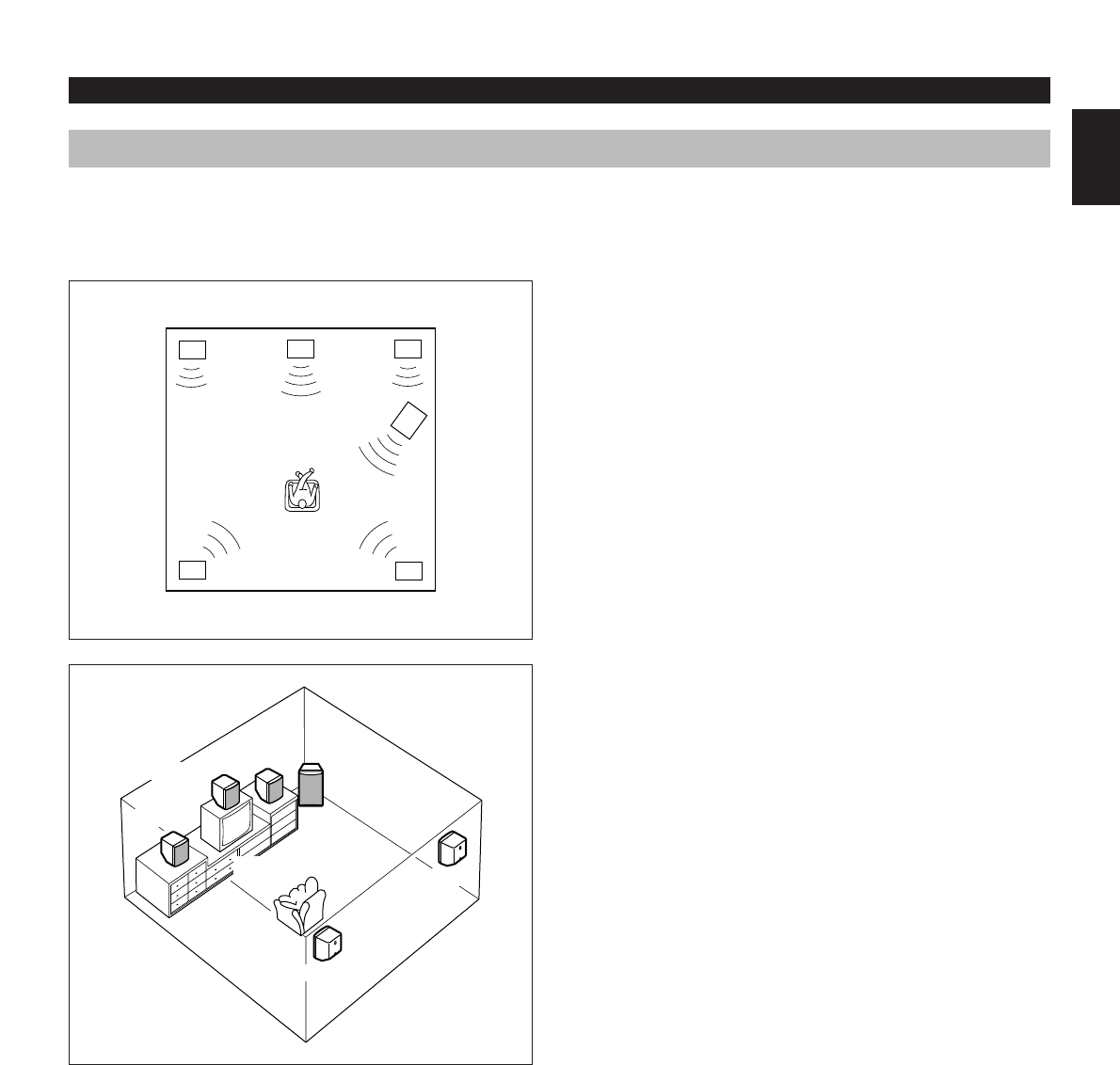
four channel five speaker system. The Pro Logic
Surround system divides the input signal into four levels:
the left and right main channels, the center channel
(used for dialog), and the rear surround sound channels
(used for sound effects, background noise, and other
ambient noises). The center channel allows listeners
seated in even less-than-ideal positions to hear the
dialog originating from the action on the screen while
experiencing good stereo imaging.
Dolby Surround is encoded on the sound track of pre-
recorded video tapes, laser discs, and some TV/cable
broadcasts. When you play a source encoded with Dolby
Surround on this unit, the Dolby Pro Logic Surround
decoder decodes the signal and distributes the
surround-sound effects.
This Dolby Pro Logic Surround Decoder employs a
digital signal processing system. This system improves
the stability of sound at each channel and minimizes
crosstalk between channels, so that positioning of
sounds around the room is more accurate compared
with conventional analog signal processing systems.
In addition, this unit features a built-in automatic input
balance control. This always assures you the best
performance without manual adjustment.
Manufactured under license from Dolby Laboratories
Licensing Corporation. “Dolby”, “Pro Logic”, and the
double-D symbol are trademarks of Dolby Laboratories
Licensing Corporation.
Dolby Pro Logic Surround + DSP
Dolby Surround sound system shows its full ability in a
large movie theater, because movie sounds are
originally designed to be reproduced in a large movie
theater using many speakers. It is difficult to create a
sound environment similar to that of a movie theater in
your listening room, because the room size, materials of
inside walls, the number of speakers, etc. of your
listening room is much different from those of a movie
theater.
Yamaha DSP technology made it possible to present
you with nearly the same sound experience as that of a
large movie theater in your listening room by
compensating for lack of presence and dynamics in your
listening room with its original digital sound fields
combined with Dolby Surround sound field.
The combination of Dolby Pro Logic Surround and DSP
is used on the sound field program “ PRO LOGIC
ENHANCED”.
The YAMAHA “CINEMA DSP” logo indicates these
programs are created by the combination of Dolby Pro
Logic and YAMAHA DSP technology.
CINEMA DSP
E-9
English
SETTING UP THE SPEAKERS
Speaker configuration
This system employs a 6 speaker configuration: 2 front
speakers, 2 rear speakers, a center speaker and a
subwoofer.
The front speakers are used for the main source sound
plus the effect sounds. The rear speakers are used for
the effect and surround sounds, and the center speaker
is for the center sounds (dialog etc.). The subwoofer is
for reinforcing low frequencies of the main source sound
and the center sounds.
Rear L
Rear R
TV set
Front R
Subwoofer
Center
Front L
Rear L
Rear R
Placing speakers
Front speakers: On both sides of the TV and in
almost the same height as the TV.
Rear speakers: Behind your listening position,
facing slightly inward. Nearly six
feet (approx. 1.8 m) up from the
floor.
Center speaker: Precisely between the front
speakers.
Subwoofer: The position of the subwoofer is not
so critical because low bass tones
are not highly directional.
Before you make connections, place all units in this system in their proper positions respectively. Above all, the
positioning of speakers are important, because it controls the whole sound quality of this system.
Position the speakers on the basis of your listening position by following instructions on this section.
Front L Center Front R
Rear L Rear R
Subwoofer
1

Hulp nodig? Stel uw vraag in het forum

Spelregels

Misbruik melden

Gebruikershandleiding.com neemt misbruik van zijn services uitermate serieus. U kunt hieronder aangeven waarom deze vraag ongepast is. Wij controleren de vraag en zonodig wordt deze verwijderd.

Product:

Bijvoorbeeld antisemitische inhoud, racistische inhoud, of materiaal dat gewelddadige fysieke handelingen tot gevolg kan hebben.

Bijvoorbeeld een creditcardnummer, een persoonlijk identificatienummer, of een geheim adres. E-mailadressen en volledige namen worden niet als privégegevens beschouwd.

Spelregels forum

Om tot zinvolle vragen te komen hanteren wij de volgende spelregels:

Belangrijk! Als er een antwoord wordt gegeven op uw vraag, dan is het voor de gever van het antwoord nuttig om te weten als u er wel (of niet) mee geholpen bent! Wij vragen u dus ook te reageren op een antwoord.

Belangrijk! Antwoorden worden ook per e-mail naar abonnees gestuurd. Laat uw emailadres achter op deze site, zodat u op de hoogte blijft. U krijgt dan ook andere vragen en antwoorden te zien.

Abonneren

Abonneer u voor het ontvangen van emails voor uw Yamaha AV1 bij:


U ontvangt een email met instructies om u voor één of beide opties in te schrijven.


Ontvang uw handleiding per email

Vul uw emailadres in en ontvang de handleiding van Yamaha AV1 in de taal/talen: Engels als bijlage per email.

De handleiding is 2,62 mb groot.


U ontvangt de handleiding per email binnen enkele minuten. Als u geen email heeft ontvangen, dan heeft u waarschijnlijk een verkeerd emailadres ingevuld of is uw mailbox te vol. Daarnaast kan het zijn dat uw internetprovider een maximum heeft aan de grootte per email. Omdat hier een handleiding wordt meegestuurd, kan het voorkomen dat de email groter is dan toegestaan bij uw provider.

Stel vragen via chat aan uw handleiding

Stel uw vraag over deze PDF

Uw handleiding is per email verstuurd. Controleer uw email

Als u niet binnen een kwartier uw email met handleiding ontvangen heeft, kan het zijn dat u een verkeerd emailadres heeft ingevuld of dat uw emailprovider een maximum grootte per email heeft ingesteld die kleiner is dan de grootte van de handleiding.

Er is een email naar u verstuurd om uw inschrijving definitief te maken.

Controleer uw email en volg de aanwijzingen op om uw inschrijving definitief te maken

U heeft geen emailadres opgegeven

Als u de handleiding per email wilt ontvangen, vul dan een geldig emailadres in.

Uw vraag is op deze pagina toegevoegd

Wilt u een email ontvangen bij een antwoord en/of nieuwe vragen? Vul dan hier uw emailadres in.


Info