Seat post supported pannier racks must not be loaded with heavy loads.
Keep in mind that when riding over a bumpy, uneven road the weight sub-
stantially increases (sprung mass). This has a significant influence on the
suspension performance. Furthermore, overloading bears the risk of frame
breakage! Therefore, do not load your bicycle with more than 8 kg!
With rear frame supported pannier racks the unsprung mass load increases
and the response of the suspension system becomes more sluggish.
For this reason we strongly advise against mounting pannier racks to full-
suspension frames.
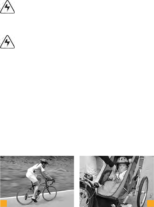
The only possible and legal way of transporting children by bicycle is in spe-
cial child carriers or trailers . For more information in this regard, see
chapter .
The child carrier is fastened to the frame of the bicycle. The
fastenings are usually designed for intermittent use. The child carrier can
thus be fastened to any bicycle that is equipped with the necessary fittings.
Only use pannier racks for mounting child carriers that have suitable fix-
ing points. Do not overload your pannier rack and be sure to observe the
permissible maximum load capacity marked on the rack. Never exceed the
indicated permissible overall load of the bicycle.
Do not mount a child carrier directly to the handlebars! Seat
post supported pannier racks are not approved for child carrier
mounting. Risk of breakage! Full-suspension bicycles do not al-
low child carrier mounting.
a
b
c
d
108
109
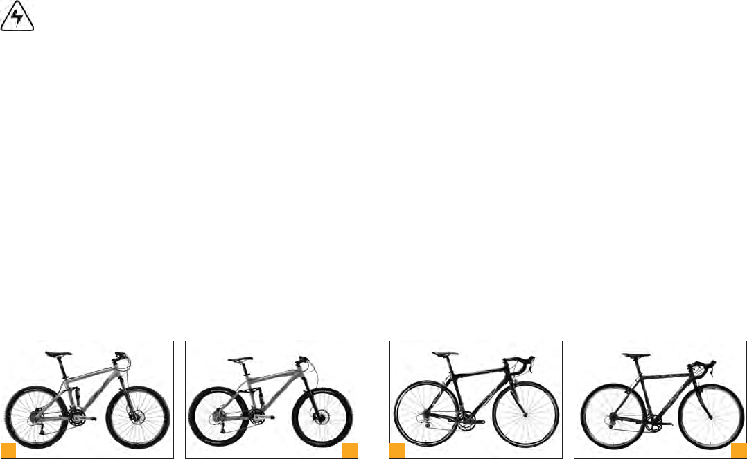
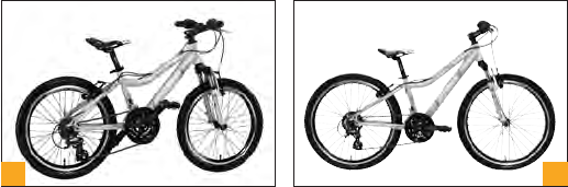
Road racing bicycles, fitness and mountain bikes are not suit-
able for mounting a child carrier with special fittings. For more
information on other bicycle types, see chapter “Intended Use”.
Make it a rule to take your child out of the carrier when parking
the bicycle. Risk of toppling over!
Cover the springs of your saddle so that the child cannot get his
or her fingers pinched between them.
Make sure the child you are taking with you wears a helmet!
It is recommendable to only buy a DIN or GS tested child carrier. Be sure
to fasten the child’s seat belt before you set off and make sure the feet are
properly seated in the shields (b).
Child carriers have a strong influence on the bicycle’s riding characteristics.
The weight of both carrier and child will make the bicycle somewhat top-
heavy and tend to give you a wobbly ride. Practise getting on and riding your
bicycle with a child on it!
A critical moment is when you have just placed the child in the carrier be-
cause this is when the danger of the bicycle toppling over is greatest. A
good way to obviate this danger is to use a twin leg kickstand to keep the
bicycle stable in standing.
Children must be transported in special child carriers only that
provide sufficient protection for their feet. In Germany e.g. chil-
dren are allowed to be taken by child carrier until the age of 7,
the rider taking the child must be no younger than 16 years.
Please read up on the applicable regulations in your country!
There are some cross and mountain bikes that are not suitable
for mounting a child carrier with special fittings. For more infor-
mation, see chapter “Intended Use” or ask your bicycle dealer.
15.2.2 Child Trailers
With special child trailers (c+d) that are towed behind a bicycle you can
transport one or two children. Children can play in the trailer without the
danger of toys falling out. Some models provide the option of mounting a
sunshade or rain shield.
a
b
c
d
Before hitching a trailer to your bicycle have a look at chapter
“Intended Use” or contact your bicycle dealer. Note down the
trailer type you opt for so that they can provide you with the
information you need.
Trailers affect the braking behaviour of your bicycle and occupy far more
width than the bicycle would alone. First, practise drawing the trailer without
passengers (a). Mount a long pole with coloured pennant to your bicycle to
increase visibility. It should be fitted with all the reflectors that are prescribed
for riding on public roads, just like your bicycle. If you use it in the dark, illumi-
nate the rear end of the trailer with a battery/accumulator-operated lamp (b).
Please inform yourself about the regulations concering lighting in the country
where you are using the trailer.
Always secure the little passenger(s) (c) with the seat belt, as
erratic movements inside the trailer can make it topple over.
Make sure the child you are taking with you wears a helmet (d).
A trailer is an insufficient protection in the event of an accident!
Please note that your stopping distance increases due to the
additional load of the child.
Make sure your bicycle is approved for trailer towing before
mounting one. Trailer towing requires hydraulic brakes! (See
chapter “Intended Use“).
15.2.3 Kids’ Tandem Bicycles / Trailer Systems
There are different systems on the market that allow a kid’s bicycle to be at-
tached to an adult bicycle to cycle together with your child on public roads.
Inform yourself at your bicycle dealer about the different types of kids‘ tan-
dem bicycles.
Some of them are attached to the seat tube of the towing bicycle. This single
point attachment may be a little unstable.
Systems attaching the complete kid’s bicycle to the adult bicycle provide
more stability.
Trailer systems have a strong influence on the bicycle’s riding
characteristics. The weight of both the attached bicycle and the
child will make the bicycle somewhat top-heavy. It may tend to
wobble. Practise getting on and off your bicycle as well as cy-
cling. Keep in mind, in particular when turning, that your bicycle
including trailer system is much longer.
a
b
c
d
108
109
Road racing bicycles, fitness and mountain bikes are not suit-
able for mounting a child carrier with special fittings. For more
information on other bicycle types, see chapter “Intended Use”.
Make it a rule to take your child out of the carrier when parking
the bicycle. Risk of toppling over!
Cover the springs of your saddle so that the child cannot get his
or her fingers pinched between them.
Make sure the child you are taking with you wears a helmet!
It is recommendable to only buy a DIN or GS tested child carrier. Be sure
to fasten the child’s seat belt before you set off and make sure the feet are
properly seated in the shields (b).
Child carriers have a strong influence on the bicycle’s riding characteristics.
The weight of both carrier and child will make the bicycle somewhat top-
heavy and tend to give you a wobbly ride. Practise getting on and riding your
bicycle with a child on it!
A critical moment is when you have just placed the child in the carrier be-
cause this is when the danger of the bicycle toppling over is greatest. A
good way to obviate this danger is to use a twin leg kickstand to keep the
bicycle stable in standing.
Children must be transported in special child carriers only that
provide sufficient protection for their feet. In Germany e.g. chil-
dren are allowed to be taken by child carrier until the age of 7,
the rider taking the child must be no younger than 16 years.
Please read up on the applicable regulations in your country!
There are some cross and mountain bikes that are not suitable
for mounting a child carrier with special fittings. For more infor-
mation, see chapter “Intended Use” or ask your bicycle dealer.
15.2.2 Child Trailers
With special child trailers (c+d) that are towed behind a bicycle you can
transport one or two children. Children can play in the trailer without the
danger of toys falling out. Some models provide the option of mounting a
sunshade or rain shield.
a
b
c
d
Before hitching a trailer to your bicycle have a look at chapter
“Intended Use” or contact your bicycle dealer. Note down the
trailer type you opt for so that they can provide you with the
information you need.
Trailers affect the braking behaviour of your bicycle and occupy far more
width than the bicycle would alone. First, practise drawing the trailer without
passengers (a). Mount a long pole with coloured pennant to your bicycle to
increase visibility. It should be fitted with all the reflectors that are prescribed
for riding on public roads, just like your bicycle. If you use it in the dark, illumi-
nate the rear end of the trailer with a battery/accumulator-operated lamp (b).
Please inform yourself about the regulations concering lighting in the country
where you are using the trailer.
Always secure the little passenger(s) (c) with the seat belt, as
erratic movements inside the trailer can make it topple over.
Make sure the child you are taking with you wears a helmet (d).
A trailer is an insufficient protection in the event of an accident!
Please note that your stopping distance increases due to the
additional load of the child.
Make sure your bicycle is approved for trailer towing before
mounting one. Trailer towing requires hydraulic brakes! (See
chapter “Intended Use“).
15.2.3 Kids’ Tandem Bicycles / Trailer Systems
There are different systems on the market that allow a kid’s bicycle to be at-
tached to an adult bicycle to cycle together with your child on public roads.
Inform yourself at your bicycle dealer about the different types of kids‘ tan-
dem bicycles.
Some of them are attached to the seat tube of the towing bicycle. This single
point attachment may be a little unstable.
Systems attaching the complete kid’s bicycle to the adult bicycle provide
more stability.
Trailer systems have a strong influence on the bicycle’s riding
characteristics. The weight of both the attached bicycle and the
child will make the bicycle somewhat top-heavy. It may tend to
wobble. Practise getting on and off your bicycle as well as cy-
cling. Keep in mind, in particular when turning, that your bicycle
including trailer system is much longer.
a
b
c
d
110
111
These trailer systems also affect the braking behaviour of your bicycle.
Therefore, before riding with a kids‘ bicycle tandem on public roads, prac-
tise riding and brake behaviour without passengers in an area free of traffic.
It is also important for you to practise with your child how to
behave on an attached bicycle during the cycle. Make sure your
child wears a helmet (a) even when riding on a tandem bicycle!
Set a good example by wearing a helmet, as well.
Only buy tested trailer systems (e.g. DIN/GS tested systems)
and have them properly mounted. The manuals of the manu-
facturers that you have obtained together with the trailer system
provide detailed information in this regard.
When riding in the dark the kid’s bicycle attached should be fit-
ted with the prescribed lighting, i.e. the latter should be marked
with a wavy line and the letter “K” (b). For more information see
chapter “Legal Requirements for Riding on Public Roads“.
15.3 Taking the Bicycle by Car
The most convenient way to safely transport your bicycle is to put it into the
boot of your car (c). There the bike is protected from dirt and any dynamic
influences during the transport. Take care to protect the boot of the car.
If necessary, line the boot before stowing the bike. Interior fixing systems
intended to secure the bicycle in the boot can be particularly helpful.
Always secure the bicycle or bicycle components when putting
it/them into the interior of your car. Parts shifting around can
impair your safety.
If transporting the bicycle inside the boot is impossible, nearly every car
accessory dealer and car company offers carrier systems (d) which allow
bicycle transport without disassembly. The usual design involves rails fixed
to the roof of the car onto which the bicycles are fixed with clamps gripping
the down tubes.
Make sure to remove all parts of your bicycle (tools, pannier
bags, child carriers etc.) which might come loose during trans-
port and cause an accident!
a
b
c
d
Most clamps are potential sources of damage to large-diameter
frame tubes (a) that are not designed to be fixed in such clamps!
This can result in irreparable damage to the frame. High-end, very thin-
walled aluminium or carbon frames are particularly susceptible to such kind
of damage. Due to the material properties of carbon, you may not see a
severe damage at first sight. This can result in an unforeseeable severe ac-
cident at a later date.
Suitable, special-purpose models are, however, available in the car acces-
sory trade.
Rear carriers (b) are becoming more and more popular. Their big advantage
over roof carriers is that you do not have to lift up the bicycles so high to at-
tach them. Make sure the fastenings do not create any damage to the fork
or frame. Risk of breakage!
Do not buy a carrier on which the bicycle has to be mounted
upside down, i.e. with the handlebars and saddle fixed face
down to the carrier. This way of fastening the bicycle exposes
handlebars, stem, saddle and seat post to extreme stress dur-
ing transport. Do not opt for a carrier system with crank arm fit.
Risk of breakage!
Please make sure the lights and the number plate of your car are
not hidden from view. For some carriers, a second exterior rear
view mirror is required by the road traffic regulations.
Whatever system you opt for, make sure it complies with the relevant safety
standards of your country!
Read the instructions of your bicycle carrier and observe the maximum load
capacity and recommended or prescribed driving speed.
Check whether your bicycle is properly fastened before and at
regular intervals during the ride. A bicycle that detaches from
the roof carrier may endanger other road users.
Bear in mind that your car has a greater overall height with the
bicycle on it. Measure the overall height and place a sign stating
the height somewhere in the cockpit or on the steering wheel so
that it can be easily seen.
Never transport bicycles with hydraulic brakes upside down.
This could let air enter the brake system and result in brake
failure.
If your bicycle has disc brakes, be sure to mount the safety locks
before transporting the bicycle with the wheels dismounted.
a
b
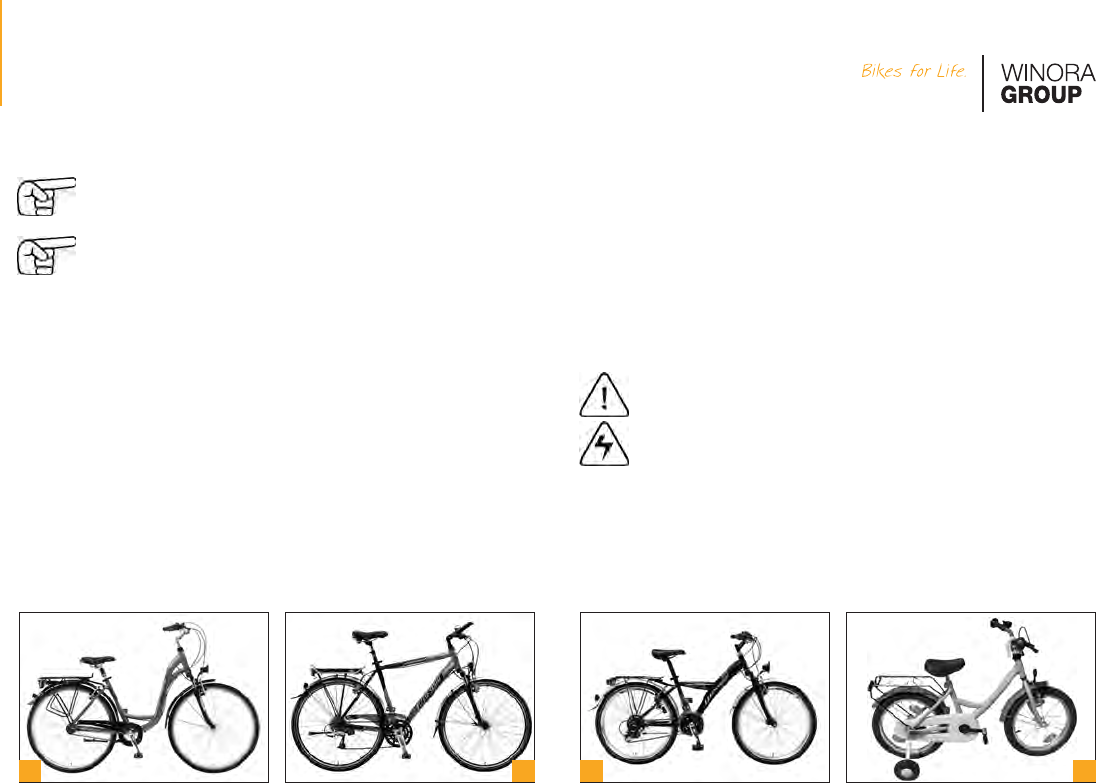
If you want to take your bicycle with you when you go on a trip by plane,
pack it in an appropriate bicycle suitcase or in a bicycle cardboard box
that you can obtain from your bicycle dealer. Special bicycle bags often
do not provide sufficient protection.
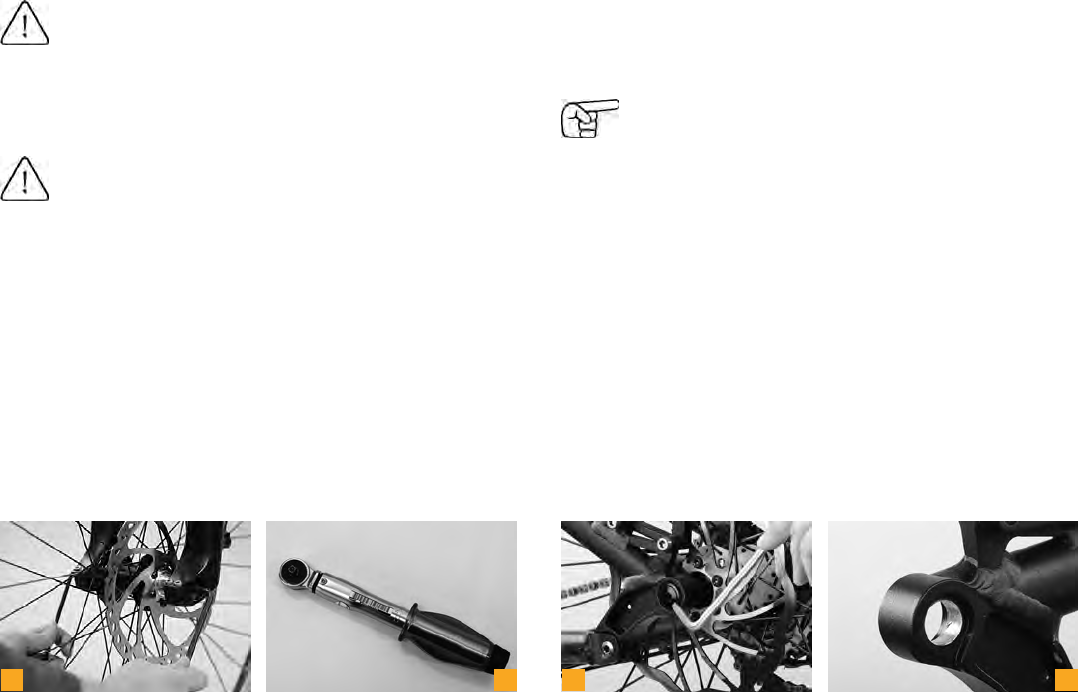
Pack the wheels in special wheel bags to protect them inside the suitcase or
cardboard box. Do not forget to take the necessary tools, a torque wrench,
bits and this manual with you to be able to assemble the bicycle and to get
it ready for use at your destination.
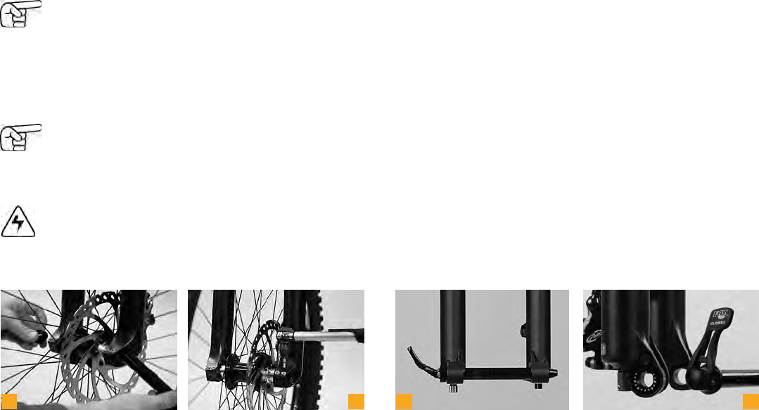
When you remove the wheels from a bicycle with disc brakes, be sure to
place pad spacers between the brake shoes. Otherwise they can come out
unintentionally and you will have difficulties in bringing them back into posi-
tion. Your bicycle dealer has a variety of brake pad spacers. Pull the brake
levers and fix them with a tape to the handlebars. This will keep the system
free of air.
a
b
In purchasing this high quality bicycle you laid the foundation for many years
and miles of enjoyable cycling. Whatever you are planning to do with your
bicycle, be sure to have proper equipment and to keep a few tips in mind.
Your bicycle dealer has a variety of useful accessories on offer enhancing
both your safety and convenience.
Improper accessories may change the qualities of your bicycle
and even cause an accident. Therefore, before fitting any ac-
cessories do contact your bicycle dealer and observe the in-
structions regarding the intended use of your bicycle.
Your bicycle can be fitted with various kinds of accessories . Make
sure to observe the requirements according to the DIN EN standards and
the traffic regulations in your country. Any retrofitted part must be compat-
ible with your bicycle. If you are in doubt or if you have any questions, please
contact your bicycle dealer!
Mounting incompatible parts can result in an accident!
c
d
Before buying any additional bells, horns or lighting acces-
sories, inform yourself thoroughly whether they are permitted
and tested and accordingly approved for use on public roads.
Make sure additional battery/accumulator-operated lamps are
marked with the wavy line and the letter “K”.
Retrofitted accessories, such as mudguards , disc or drum
brakes, pannier racks etc. can impair the functioning of your
bicycle. Ask your bicycle dealer for advice before mounting any
kind of accessories to your bicycle.
The overall load bearing capacity of bicycle trailers for freight transport must
not exceed 40 kg including freight. There are two types of trailer coupling:
There are trailers that are mounted close to the rear axle, whereas others are
attached between saddle and pannier rack. The decision as to the type of
coupling mainly depends on the design of your bicycle. Suspension bicycle
are not designed for trailer towing!
Be sure to observe the operating instructions of the trailer manufacturer.
Bicycle trailers must comply with the requirements of the road traffic regula-
tions.
Practise moving off, braking, turning and cycling down slopes, as a trailer
affects the performance of a bicycle.
Straight handlebars can be fitted with bar ends . Some thin-walled han-
dlebars or carbon handlebars need additional plug ends or other specific
parts to prevent a crushing or bursting of the handlebars. Have these parts
fitted by your bicycle dealer!
There are cycle computers that show your current and average speed, your
daily and annual mileage as well as the duration of the present ride. Real de
luxe models also give the highest speed achieved, differences in elevation,
your cadence or (with a special breast belt) your heart rate .
Baskets for handlebar or stem mounting are suited for the transport of
low-weight items only. Never load the basket with more than 5 kg.
In case you mount a basket to the handlebars, make sure front lamp and re-
flector remain free and steering is not affected. In general, we advise against
mounting a basket to the handlebars, as a negative impact on the perform-
ance of the bicycle cannot be excluded.
Make sure the mounting devices do not damage the handlebars
or the stem. Risk of breakage! Do not bend brake and Bowden
cables.
a
b
c
d
If you want to take your bicycle with you when you go on a trip by plane,
pack it in an appropriate bicycle suitcase or in a bicycle cardboard box
that you can obtain from your bicycle dealer. Special bicycle bags often
do not provide sufficient protection.
Pack the wheels in special wheel bags to protect them inside the suitcase or
cardboard box. Do not forget to take the necessary tools, a torque wrench,
bits and this manual with you to be able to assemble the bicycle and to get
it ready for use at your destination.
When you remove the wheels from a bicycle with disc brakes, be sure to
place pad spacers between the brake shoes. Otherwise they can come out
unintentionally and you will have difficulties in bringing them back into posi-
tion. Your bicycle dealer has a variety of brake pad spacers. Pull the brake
levers and fix them with a tape to the handlebars. This will keep the system
free of air.
a
b
In purchasing this high quality bicycle you laid the foundation for many years
and miles of enjoyable cycling. Whatever you are planning to do with your
bicycle, be sure to have proper equipment and to keep a few tips in mind.
Your bicycle dealer has a variety of useful accessories on offer enhancing
both your safety and convenience.
Improper accessories may change the qualities of your bicycle
and even cause an accident. Therefore, before fitting any ac-
cessories do contact your bicycle dealer and observe the in-
structions regarding the intended use of your bicycle.
Your bicycle can be fitted with various kinds of accessories . Make
sure to observe the requirements according to the DIN EN standards and
the traffic regulations in your country. Any retrofitted part must be compat-
ible with your bicycle. If you are in doubt or if you have any questions, please
contact your bicycle dealer!
Mounting incompatible parts can result in an accident!
c
d
Before buying any additional bells, horns or lighting acces-
sories, inform yourself thoroughly whether they are permitted
and tested and accordingly approved for use on public roads.
Make sure additional battery/accumulator-operated lamps are
marked with the wavy line and the letter “K”.
Retrofitted accessories, such as mudguards , disc or drum
brakes, pannier racks etc. can impair the functioning of your
bicycle. Ask your bicycle dealer for advice before mounting any
kind of accessories to your bicycle.
The overall load bearing capacity of bicycle trailers for freight transport must
not exceed 40 kg including freight. There are two types of trailer coupling:
There are trailers that are mounted close to the rear axle, whereas others are
attached between saddle and pannier rack. The decision as to the type of
coupling mainly depends on the design of your bicycle. Suspension bicycle
are not designed for trailer towing!
Be sure to observe the operating instructions of the trailer manufacturer.
Bicycle trailers must comply with the requirements of the road traffic regula-
tions.
Practise moving off, braking, turning and cycling down slopes, as a trailer
affects the performance of a bicycle.
Straight handlebars can be fitted with bar ends . Some thin-walled han-
dlebars or carbon handlebars need additional plug ends or other specific
parts to prevent a crushing or bursting of the handlebars. Have these parts
fitted by your bicycle dealer!
There are cycle computers that show your current and average speed, your
daily and annual mileage as well as the duration of the present ride. Real de
luxe models also give the highest speed achieved, differences in elevation,
your cadence or (with a special breast belt) your heart rate .
Baskets for handlebar or stem mounting are suited for the transport of
low-weight items only. Never load the basket with more than 5 kg.
In case you mount a basket to the handlebars, make sure front lamp and re-
flector remain free and steering is not affected. In general, we advise against
mounting a basket to the handlebars, as a negative impact on the perform-
ance of the bicycle cannot be excluded.
Make sure the mounting devices do not damage the handlebars
or the stem. Risk of breakage! Do not bend brake and Bowden
cables.
a
b
c
d
114
115
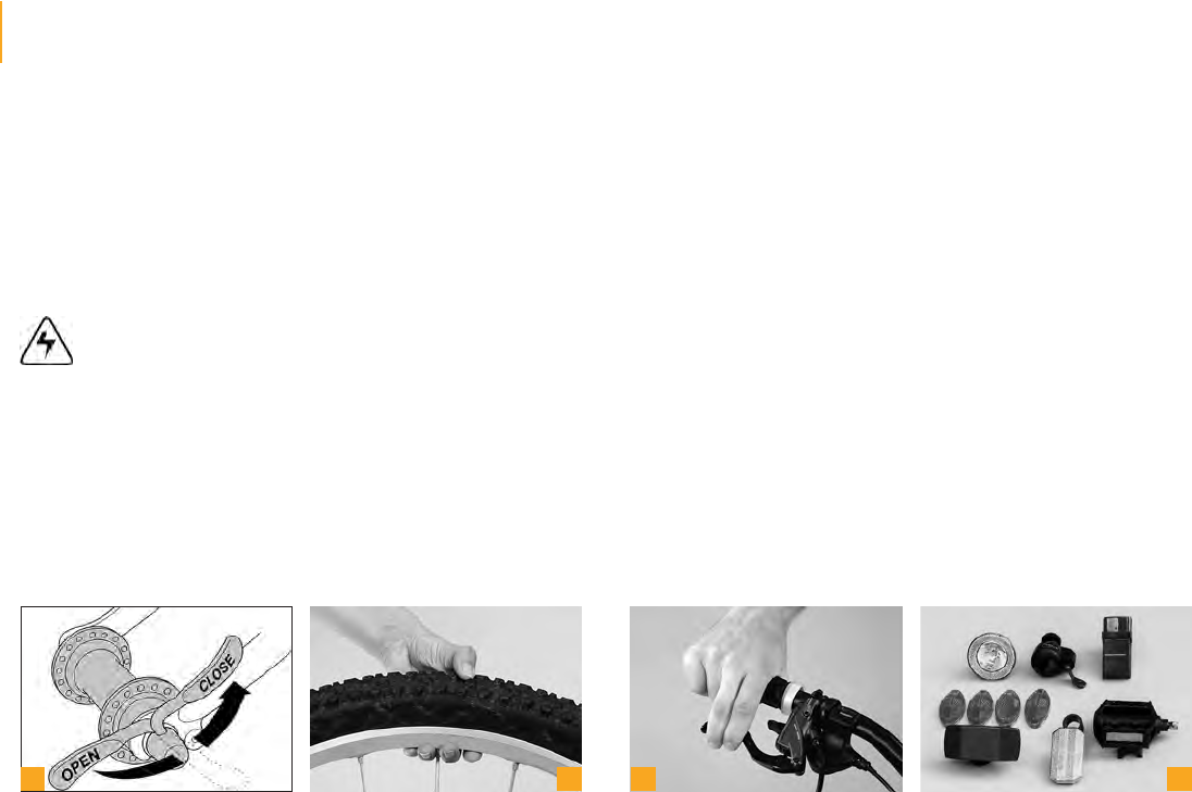
15.5.6 puncture Kit (a)
The most important accessories for a successful bicycle ride are a tyre
pump and a small tool kit. The tool kit should include two plastic tyre levers,
the most commonly used Allen keys, a spare tube, a tyre repair kit, your
mobile phone and a little cash. In this way you will be well prepared in the
event of a puncture or some other mishap.
15.5.7 Kickstand (b)
Bicycle kickstands are to prevent the bicycle from falling over when parked.
The kickstand you opt for should match your needs.
A centre kickstand is crucial for bicycles fitted with a child carrier because
they prevent the bicycle from toppling over even when loaded. The rider
has both hands free to lift the child into and out of the carrier seat without
unbalancing the bicycle.
Never leave children alone and unsupervised in a parked bicy-
cle, it may topple over!
Twin leg kickstands folding up to one side have become more and more
popular on touring bicycles. They keep the bicycle stable, even with heavy
baggage.
Side kickstands mounted to the bottom of the frame, behind the bottom
bracket or to the rear stay or wheel axle keep the bicycle in a slightly inclined
position. A rubber foot attached to the side kickstand provides added sup-
port on soft surfaces.
If your bicycle is fitted with a telescopic kickstand, you can adjust its length
without tools by simply turning the adjustment wheel. The proper length of
the kickstand is the distance from the pivotal point of the kickstand to the
ground with the bicycle in upright position. Other adjustable side kickstands
are fitted with a visible clamping bolt. The adjustment of this type of kick-
stand requires a wrench or an Allen key.
Your bicycle dealer will be pleased to help you finding an appro-
priate kickstand! Have the kickstand mounted by your bicycle
dealer.
15.5.8 Mirrors
Only fit your bicycle with a tested and approved bicycle mirror.
a
b
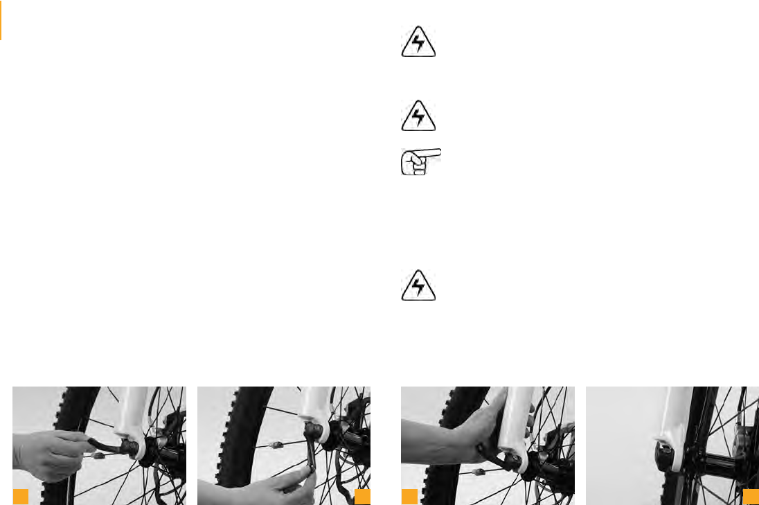
15.5.9 Mudguards (a+b)
If you want to fit your bicycle with mudguards, ask your bicycle dealer for
advice. There are removable mudguards, also referred to as clip-on mud-
guards, as well as firmly attached models that provide more protection.
Retro-fittable mudguards designed to be firmly attached are normally made
of plastic and mounted in the correct position by means of additionally fitted
stays. The accurate length of the stay is achieved when the bottom edge of
the mudguard runs parallel to the tyre.
For safety reasons pop off front stays are a must. They are to prevent the
front wheel from getting jammed due to impurities clinging to the tyre. In
such an event the front stay pops off, thus avoiding a possible accident. The
plug-in connection allows an easy re-fixing.
Be sure to replace damaged mudguards!
15.5.10 Bicycle Locks
Best anti-theft protection is provided by stable cable and D-locks (c+d).
With a D-lock you can lock e.g. the bicycle frame to a lamppost, where-
as a cable lock means additional protection for the wheels. The D-lock is
mounted to the frame by means of a bracket, a convenient way of taking
it with you. Cable locks can be fixed under the saddle around the tube, if
your bicycle is not fitted with a frame mounting. Your bicycle dealer will be
pleased to advise you about the various security categories of bicycle locks.
Always fix the lock securely to the bicycle and do not let it hang
down the handlebars.
a
b
c
d
114
115
15.5.6 puncture Kit (a)
The most important accessories for a successful bicycle ride are a tyre
pump and a small tool kit. The tool kit should include two plastic tyre levers,
the most commonly used Allen keys, a spare tube, a tyre repair kit, your
mobile phone and a little cash. In this way you will be well prepared in the
event of a puncture or some other mishap.
15.5.7 Kickstand (b)
Bicycle kickstands are to prevent the bicycle from falling over when parked.
The kickstand you opt for should match your needs.
A centre kickstand is crucial for bicycles fitted with a child carrier because
they prevent the bicycle from toppling over even when loaded. The rider
has both hands free to lift the child into and out of the carrier seat without
unbalancing the bicycle.
Never leave children alone and unsupervised in a parked bicy-
cle, it may topple over!
Twin leg kickstands folding up to one side have become more and more
popular on touring bicycles. They keep the bicycle stable, even with heavy
baggage.
Side kickstands mounted to the bottom of the frame, behind the bottom
bracket or to the rear stay or wheel axle keep the bicycle in a slightly inclined
position. A rubber foot attached to the side kickstand provides added sup-
port on soft surfaces.
If your bicycle is fitted with a telescopic kickstand, you can adjust its length
without tools by simply turning the adjustment wheel. The proper length of
the kickstand is the distance from the pivotal point of the kickstand to the
ground with the bicycle in upright position. Other adjustable side kickstands
are fitted with a visible clamping bolt. The adjustment of this type of kick-
stand requires a wrench or an Allen key.
Your bicycle dealer will be pleased to help you finding an appro-
priate kickstand! Have the kickstand mounted by your bicycle
dealer.
15.5.8 Mirrors
Only fit your bicycle with a tested and approved bicycle mirror.
a
b
15.5.9 Mudguards (a+b)
If you want to fit your bicycle with mudguards, ask your bicycle dealer for
advice. There are removable mudguards, also referred to as clip-on mud-
guards, as well as firmly attached models that provide more protection.
Retro-fittable mudguards designed to be firmly attached are normally made
of plastic and mounted in the correct position by means of additionally fitted
stays. The accurate length of the stay is achieved when the bottom edge of
the mudguard runs parallel to the tyre.
For safety reasons pop off front stays are a must. They are to prevent the
front wheel from getting jammed due to impurities clinging to the tyre. In
such an event the front stay pops off, thus avoiding a possible accident. The
plug-in connection allows an easy re-fixing.
Be sure to replace damaged mudguards!
15.5.10 Bicycle Locks
Best anti-theft protection is provided by stable cable and D-locks (c+d).
With a D-lock you can lock e.g. the bicycle frame to a lamppost, where-
as a cable lock means additional protection for the wheels. The D-lock is
mounted to the frame by means of a bracket, a convenient way of taking
it with you. Cable locks can be fixed under the saddle around the tube, if
your bicycle is not fitted with a frame mounting. Your bicycle dealer will be
pleased to advise you about the various security categories of bicycle locks.
Always fix the lock securely to the bicycle and do not let it hang
down the handlebars.
a
b
c
d
Cycling helmets are a must when riding a bicycle. Your bicycle dealer has a
variety of styles and sizes .
Take your time when buying a helmet and keep on the one you prefer for a
while before making your final choice. A good helmet should fit snug without
pinching.
Pay attention to testing symbols indicating the helmet passed the tests re-
quired by the DIN EN 1078 standards.
Be sure to only wear a bicycle helmet during cycling. Observe the manufac-
turer’s instructions.
Never ride without a helmet! But remember that even the safest
helmet is useless unless it fits properly and is correctly adjusted
and fastened .
Always wear an integral helmet and protectors whenever you
set off on a dirt, downhill or freeride bike.
Cycling pants are a must for those who appreciate sitting comfortably in
their saddle. These tight pants have a special padding in the bottom. They
are free of folds, seams and pressure that seams cause. As cycling is certain
to make you sweat, it is advisable to wear jerseys made of synthetic mate-
rial. These kinds of fibres do not absorb any moisture, but transport the
sweat away from your skin to the surface of the fabric, thus avoiding feeling
chilly due to cold headwinds. Be sure to take appropriate waterproof cloth-
ing with you when you set off on a long cycling tour. Your bicycle dealer will
be pleased to help you finding the appropriate clothing.
Never ride with wide-cut trousers or skirts that might get caught
in the spokes, chain or chainrings. To avoid any such mishap,
use suitable clips or straps, if necessary .
For increased visibility to other road users be sure to wear
bright-coloured clothing.
a
b
c
d
Apart from a cycling helmet and suitable clothing, cycling glasses are abso-
lutely essential when you set off on your bicycle .
They do not only protect your eyes from the sun and the wind, but also keep
out flies that may impede your vision when they fly into your eyes.
!
Good cycling glasses should fit tightly to your face not allowing any wind
to affect your eyes. Cycling glasses come in a wide range of models, such
as e.g. glasses with clear lenses and without UV protection for cycling in the
dawn and at night or glasses with maximum UV protection for cycling under
extreme sunlight conditions.
Your bicycle dealer has a wide range of cycling glasses available and will be
pleased to advise you!
Cycling shoes should be made of solid material to provide firm support
for your feet. In addition, they should have a stiff sole so that the pedal can-
not press through. The sole should not be too wide in the area of the heels,
as the rear stays or the crank will otherwise get in the way of your pedalling.
This will prevent your feet from assuming a natural position when pedalling
and may cause knee pain in the long run.
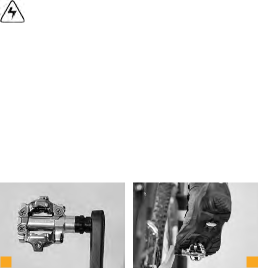
Special cycling shoes are obligatory if your hybrid, mountain or road racing
bike is equipped with clipless pedals . With these shoes small cleats are
fixed to the sole . They give you a firm connection between shoe and pedal
and allow an acceptable walking position.
The main advantage is that these cycling shoes and clipless pedals prevent
your feet from slipping off when pedalling fast or when riding over rough
ground. They enable you not only to push but also to pull the pedals. This
makes your pedalling more fluid and increases the power transmission com-
pared to normal pedals. With clipless pedals you can get off the pedal very
quickly. Just turn your heel to the outside. Practise the engagement and
release of clipless pedals so that you will be prepared to face any difficult
situation.
Read the operating instructions of the pedal manufacturers. If
you are in doubt or if you have any questions, please contact
your bicycle dealer!
The usual way to engage with the pedal is to turn it from the lowest position
of the crank to the horizontal using the tip of the cleat and push down on
the back of it. Normally, the shoe engages with the pedal with a click which
you will hear and feel clearly. Cleats come in different shapes, with varying
release angles and tensions. If you are in doubt or if you have any questions,
please contact your bicycle dealer!
a
b
c
d
Cycling helmets are a must when riding a bicycle. Your bicycle dealer has a
variety of styles and sizes .
Take your time when buying a helmet and keep on the one you prefer for a
while before making your final choice. A good helmet should fit snug without
pinching.
Pay attention to testing symbols indicating the helmet passed the tests re-
quired by the DIN EN 1078 standards.
Be sure to only wear a bicycle helmet during cycling. Observe the manufac-
turer’s instructions.
Never ride without a helmet! But remember that even the safest
helmet is useless unless it fits properly and is correctly adjusted
and fastened .
Always wear an integral helmet and protectors whenever you
set off on a dirt, downhill or freeride bike.
Cycling pants are a must for those who appreciate sitting comfortably in
their saddle. These tight pants have a special padding in the bottom. They
are free of folds, seams and pressure that seams cause. As cycling is certain
to make you sweat, it is advisable to wear jerseys made of synthetic mate-
rial. These kinds of fibres do not absorb any moisture, but transport the
sweat away from your skin to the surface of the fabric, thus avoiding feeling
chilly due to cold headwinds. Be sure to take appropriate waterproof cloth-
ing with you when you set off on a long cycling tour. Your bicycle dealer will
be pleased to help you finding the appropriate clothing.
Never ride with wide-cut trousers or skirts that might get caught
in the spokes, chain or chainrings. To avoid any such mishap,
use suitable clips or straps, if necessary .
For increased visibility to other road users be sure to wear
bright-coloured clothing.
a
b
c
d
Apart from a cycling helmet and suitable clothing, cycling glasses are abso-
lutely essential when you set off on your bicycle .
They do not only protect your eyes from the sun and the wind, but also keep
out flies that may impede your vision when they fly into your eyes.
!
Good cycling glasses should fit tightly to your face not allowing any wind
to affect your eyes. Cycling glasses come in a wide range of models, such
as e.g. glasses with clear lenses and without UV protection for cycling in the
dawn and at night or glasses with maximum UV protection for cycling under
extreme sunlight conditions.
Your bicycle dealer has a wide range of cycling glasses available and will be
pleased to advise you!
Cycling shoes should be made of solid material to provide firm support
for your feet. In addition, they should have a stiff sole so that the pedal can-
not press through. The sole should not be too wide in the area of the heels,
as the rear stays or the crank will otherwise get in the way of your pedalling.
This will prevent your feet from assuming a natural position when pedalling
and may cause knee pain in the long run.
Special cycling shoes are obligatory if your hybrid, mountain or road racing
bike is equipped with clipless pedals . With these shoes small cleats are
fixed to the sole . They give you a firm connection between shoe and pedal
and allow an acceptable walking position.
The main advantage is that these cycling shoes and clipless pedals prevent
your feet from slipping off when pedalling fast or when riding over rough
ground. They enable you not only to push but also to pull the pedals. This
makes your pedalling more fluid and increases the power transmission com-
pared to normal pedals. With clipless pedals you can get off the pedal very
quickly. Just turn your heel to the outside. Practise the engagement and
release of clipless pedals so that you will be prepared to face any difficult
situation.
Read the operating instructions of the pedal manufacturers. If
you are in doubt or if you have any questions, please contact
your bicycle dealer!
The usual way to engage with the pedal is to turn it from the lowest position
of the crank to the horizontal using the tip of the cleat and push down on
the back of it. Normally, the shoe engages with the pedal with a click which
you will hear and feel clearly. Cleats come in different shapes, with varying
release angles and tensions. If you are in doubt or if you have any questions,
please contact your bicycle dealer!
a
b
c
d
118
119
Make sure pedals and shoe soles are always clear of mud and
other impurities and grease the lock-in mechanism with lubri-
cant at regular intervals.
Taking up the pedals, engaging and disengaging the shoes
should first be practised while stationary. Later you can refine
your technique in a place free of traffic.
The cleat should be positioned so that the ball of your feet rests over the
pedal spindle (a). Your feet should assume a natural position when pedal-
ling. For most people this means that the heels will point a little inward. Your
bicycle dealer will be pleased to help you adjusting and mounting the pedal
best meeting your demands!
Make sure the fastening bolts of the cleats are properly tight-
ened, as you will find it almost impossible to disengage your
shoe from the pedal, if the cleat is loose. Risk of an accident!
The release force of clipless pedals is adjusted by means of an Allen key (b).
If there are any creaking or squeaking noises occurring, some grease will
solve the problem in most cases. These noises as well as lateral play of the
shoe on the pedal can, however, be also signs of wear. Check the cleats at
regular intervals.
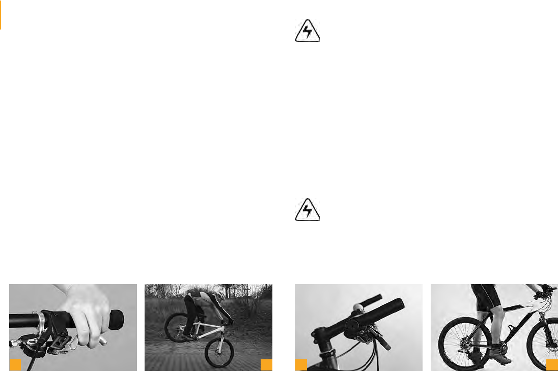
Only use clipless pedals allowing you to engage and disengage
smoothly (c). A defective pedal or a badly worn cleat can make
the shoe disengage from the pedal. Or unclipping the shoe from
the pedal is sometimes very difficult or even impossible. In both
cases, there is the danger of an accident!
Inform yourself at your bicycle dealer about the various models
of cycling shoes available. Cycling shoes come in various styles
for specific uses.
Some mountain bike pedals, also referred to as platform pedals,
are designed for maximum grip of the shoes when dirtbiking
and freeriding (d). For this reason they have sharp edges and/
or bolted pins. As they enhance the risk of injuries during riding,
you should wear protective clothing, e.g. knee and shin guards.
a
b
c
d
16 General Notes on Care and
Inspection
It is advisable to have your bicycle serviced regularly by your bicycle dealer
after the bedding in phase. If your bicycle does harder service, because you
ride a great deal on poor road surfaces or cross-country, it will require cor-
respondingly shorter maintenance periods. The off-season during the winter
months is a very good time to take your bicycle to your bicycle dealer for the
annual inspection, as they will have plenty of time for servicing.
Servicing and repairs are jobs best left to your bicycle dealer. If
you have your bicycle serviced by anyone else than an expert,
you run the risk that parts of your bicycle will fail. This may lead
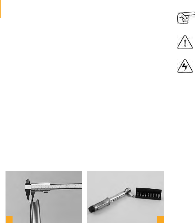
to an accident! When working on your bicycle restrict yourself
to jobs for which you are equipped e.g. with a torque wrench (a)
and have the necessary knowledge.
If a component needs to be replaced, make it a rule to only use
original spare parts (b).
a
b
Your bicycle dealer will have assembled and adjusted your bicycle ready
for use when you come to collect it. Nevertheless, your bicycle needs regu-
lar servicing. Have your local bicycle dealer do the scheduled maintenance
work. This is the only way to ensure that all components function safely and
reliably for many miles.
The bicycle will be due for its first maintenance after 100 to 300 kilometres
(60 to 180 miles), 5 to 15 hours of initial use or four to six weeks. The bed-
ding in phase typically involves spokes slightly losing tension, cables stretch-
ing, gears becoming out of adjustment and bearings settling, so there is
every reason to have your dealer service the bicycle at this stage. This bed-
ding and settling in process is unavoidable. Therefore, remember to make
an appointment with your bicycle dealer for the first inspection of your new
bicycle. The first inspection is very important for both functioning and dura-
bility of your bicycle.
For your own safety, bring your bicycle to your dealer for its
first inspection after 100 to 300 kilometres (60 to 180 miles), 5
to 15 hours of initial use or four to six weeks, at the very latest
however after three months.
118
119
Make sure pedals and shoe soles are always clear of mud and
other impurities and grease the lock-in mechanism with lubri-
cant at regular intervals.
Taking up the pedals, engaging and disengaging the shoes
should first be practised while stationary. Later you can refine
your technique in a place free of traffic.
The cleat should be positioned so that the ball of your feet rests over the
pedal spindle (a). Your feet should assume a natural position when pedal-
ling. For most people this means that the heels will point a little inward. Your
bicycle dealer will be pleased to help you adjusting and mounting the pedal
best meeting your demands!
Make sure the fastening bolts of the cleats are properly tight-
ened, as you will find it almost impossible to disengage your
shoe from the pedal, if the cleat is loose. Risk of an accident!
The release force of clipless pedals is adjusted by means of an Allen key (b).
If there are any creaking or squeaking noises occurring, some grease will
solve the problem in most cases. These noises as well as lateral play of the
shoe on the pedal can, however, be also signs of wear. Check the cleats at
regular intervals.
Only use clipless pedals allowing you to engage and disengage
smoothly (c). A defective pedal or a badly worn cleat can make
the shoe disengage from the pedal. Or unclipping the shoe from
the pedal is sometimes very difficult or even impossible. In both
cases, there is the danger of an accident!
Inform yourself at your bicycle dealer about the various models
of cycling shoes available. Cycling shoes come in various styles
for specific uses.
Some mountain bike pedals, also referred to as platform pedals,
are designed for maximum grip of the shoes when dirtbiking
and freeriding (d). For this reason they have sharp edges and/
or bolted pins. As they enhance the risk of injuries during riding,
you should wear protective clothing, e.g. knee and shin guards.
a
b
c
d
16 General Notes on Care and
Inspection
It is advisable to have your bicycle serviced regularly by your bicycle dealer
after the bedding in phase. If your bicycle does harder service, because you
ride a great deal on poor road surfaces or cross-country, it will require cor-
respondingly shorter maintenance periods. The off-season during the winter
months is a very good time to take your bicycle to your bicycle dealer for the
annual inspection, as they will have plenty of time for servicing.
Servicing and repairs are jobs best left to your bicycle dealer. If
you have your bicycle serviced by anyone else than an expert,
you run the risk that parts of your bicycle will fail. This may lead
to an accident! When working on your bicycle restrict yourself
to jobs for which you are equipped e.g. with a torque wrench (a)
and have the necessary knowledge.
If a component needs to be replaced, make it a rule to only use
original spare parts (b).
a
b
Your bicycle dealer will have assembled and adjusted your bicycle ready
for use when you come to collect it. Nevertheless, your bicycle needs regu-
lar servicing. Have your local bicycle dealer do the scheduled maintenance
work. This is the only way to ensure that all components function safely and
reliably for many miles.
The bicycle will be due for its first maintenance after 100 to 300 kilometres
(60 to 180 miles), 5 to 15 hours of initial use or four to six weeks. The bed-
ding in phase typically involves spokes slightly losing tension, cables stretch-
ing, gears becoming out of adjustment and bearings settling, so there is
every reason to have your dealer service the bicycle at this stage. This bed-
ding and settling in process is unavoidable. Therefore, remember to make
an appointment with your bicycle dealer for the first inspection of your new
bicycle. The first inspection is very important for both functioning and dura-
bility of your bicycle.
For your own safety, bring your bicycle to your dealer for its
first inspection after 100 to 300 kilometres (60 to 180 miles), 5
to 15 hours of initial use or four to six weeks, at the very latest
however after three months.
120
121
16.1 Cleaning and Caring for the Bicycle
Dried sweat, dirt and salt from riding during the winter months can harm
your bicycle. You should therefore make it a habit of cleaning all its compo-
nents at regular intervals.
Avoid cleaning your bicycle with a pressure water washer. The high-pres-
sure water ejected in a narrowly focused jet may pass through seals and
penetrate bearings. This leads to the dilution of lubricants and consequently
to greater friction. This destroys and impairs the functioning of the bearing
races in the long term. Pressurized water also tends to abrade frame stick-
ers.
A much more gentle way of cleaning your bicycle is with a low pressure
water jet or a bucket of water and a sponge (a) or large brush. Cleaning your
bicycle by hand has another positive side-effect: you may discover defects
in the paint (b) or worn or defective components at an early stage.
Do not clean your bicycle with a high-pressure water or steam
jet and if you do, be sure to keep it at a distance.
While cleaning, watch out for cracks, scratches, dents as well
as bent or discoloured material. Have defective components
replaced immediately and touch up paint defects. If you are in
doubt or if you have any questions, please contact your bicycle
dealer!
Inspect the chain after you have finished cleaning and oil it, if necessary (c)
(see chapter “Chain”). Apply a coat of standard hard wax (d) on painted,
metal and carbon surfaces (except from brake sufaces). Polish the waxed
surfaces after drying to give them a nice shine.
Keep cleaning agents and chain oil clear of the brake pads, ro-
tors and rim sides (braking surfaces). This could impair the func-
tioning of the brake (see chapter „Brake System“)! Never grease
or lubricate the clamping areas of a frame made of carbon, e.g.
handlebars, stem, seat post and seat tube.
Only use petroleum based solvents for cleaning tough oil or
grease stains from paint and carbon surfaces. Never use de-
greasing agents containing acetone, methyl chloride etc., or
solvent-containing, non-neutral or chemical cleaning agents
that could attack the surface!
a
b
c
d
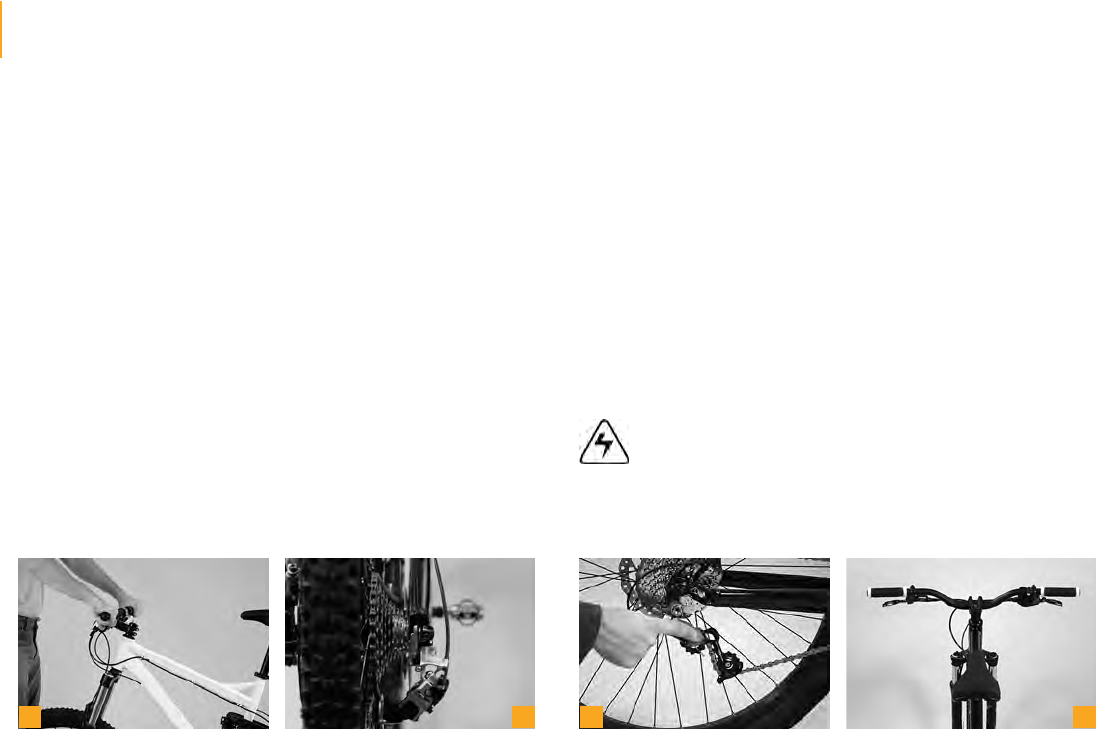
16.2 Sheltering and Storing the Bicycle
If you regularly service your bicycle during the year, you will not need to take
any special precautions when storing it for a short time, apart from securing
it against theft. It is advisable to store the bicycle in a dry and airy place.
There are some things to bear in mind, when putting the bicycle away for
the winter months: Inflated inner tubes tend to gradually lose air when the
bicycle is not used for a long time. If the bicycle is left standing on flat tyres
for an extended period, this can cause damage to the structure of the tyres.
It is therefore better to hang the wheels or the entire bicycle (a) or to check
the tyre pressure regularly (b).
Clean the bicycle (c) and protect it against corrosion. Your bicycle dealer of-
fers a variety of care products, such as spray wax (d) etc. Take off the seat
post and allow for any moisture that may have entered to dry away. Spray
a little finely atomized oil into the seat tube (except for carbon clamping
areas!). Switch the gear to the smallest chainring and the smallest sprocket.
This relaxes the cables and springs as much as possible.
There is usually minimal waiting time for repairs and servicing at
bicycle dealers during the winter months. What is more, many
dealers offer annual checks at a special price. Use the off-sea-
son to take your bicycle to your dealer for inspection!
If your bicycle has carbon rims, do not hang it on the rims! Risk
of breakage!
a
b
c
d
120
121
16.1 Cleaning and Caring for the Bicycle
Dried sweat, dirt and salt from riding during the winter months can harm
your bicycle. You should therefore make it a habit of cleaning all its compo-
nents at regular intervals.
Avoid cleaning your bicycle with a pressure water washer. The high-pres-
sure water ejected in a narrowly focused jet may pass through seals and
penetrate bearings. This leads to the dilution of lubricants and consequently
to greater friction. This destroys and impairs the functioning of the bearing
races in the long term. Pressurized water also tends to abrade frame stick-
ers.
A much more gentle way of cleaning your bicycle is with a low pressure
water jet or a bucket of water and a sponge (a) or large brush. Cleaning your
bicycle by hand has another positive side-effect: you may discover defects
in the paint (b) or worn or defective components at an early stage.
Do not clean your bicycle with a high-pressure water or steam
jet and if you do, be sure to keep it at a distance.
While cleaning, watch out for cracks, scratches, dents as well
as bent or discoloured material. Have defective components
replaced immediately and touch up paint defects. If you are in
doubt or if you have any questions, please contact your bicycle
dealer!
Inspect the chain after you have finished cleaning and oil it, if necessary (c)
(see chapter “Chain”). Apply a coat of standard hard wax (d) on painted,
metal and carbon surfaces (except from brake sufaces). Polish the waxed
surfaces after drying to give them a nice shine.
Keep cleaning agents and chain oil clear of the brake pads, ro-
tors and rim sides (braking surfaces). This could impair the func-
tioning of the brake (see chapter „Brake System“)! Never grease
or lubricate the clamping areas of a frame made of carbon, e.g.
handlebars, stem, seat post and seat tube.
Only use petroleum based solvents for cleaning tough oil or
grease stains from paint and carbon surfaces. Never use de-
greasing agents containing acetone, methyl chloride etc., or
solvent-containing, non-neutral or chemical cleaning agents
that could attack the surface!
a
b
c
d
16.2 Sheltering and Storing the Bicycle
If you regularly service your bicycle during the year, you will not need to take
any special precautions when storing it for a short time, apart from securing
it against theft. It is advisable to store the bicycle in a dry and airy place.
There are some things to bear in mind, when putting the bicycle away for
the winter months: Inflated inner tubes tend to gradually lose air when the
bicycle is not used for a long time. If the bicycle is left standing on flat tyres
for an extended period, this can cause damage to the structure of the tyres.
It is therefore better to hang the wheels or the entire bicycle (a) or to check
the tyre pressure regularly (b).
Clean the bicycle (c) and protect it against corrosion. Your bicycle dealer of-
fers a variety of care products, such as spray wax (d) etc. Take off the seat
post and allow for any moisture that may have entered to dry away. Spray
a little finely atomized oil into the seat tube (except for carbon clamping
areas!). Switch the gear to the smallest chainring and the smallest sprocket.
This relaxes the cables and springs as much as possible.
There is usually minimal waiting time for repairs and servicing at
bicycle dealers during the winter months. What is more, many
dealers offer annual checks at a special price. Use the off-sea-
son to take your bicycle to your dealer for inspection!
If your bicycle has carbon rims, do not hang it on the rims! Risk
of breakage!
a
b
c
d
122
123
17 Service and Maintenance Schedule
ComponentWhat to doBefore every rideMonthlyAnnually
LightingCheck
TyresCheck pressure
TyresCheck tread and side walls
Brakes (rim-)Check lever travel, wear of brake pads,
position of pads relative to rim
Brakes (rim-)Test brakes in stationary
Brakes, (rim-), brake padsClean
Brake cablesVisual inspection
Brakes (disc-)Replace liquid (Dot-liquids)
Suspension forkCheck and retighten bolts, if necessary
Suspension forkChange oil or grease elastomers
Suspension seat postService
Suspension seat postCheck for play
Rims with rim brakesCheck thickness, replace if necessaryAt the latest after second set of brake pads is worn down
Bottom bracketCheck for play
Bottom bracketRegrease (shell)
ChainCheck and grease, if necessary
ChainCheck and replace, if necessaryAfter 800 km (500 miles)
CranksetCheck and retighten, if necessary
Painted / anodised surfacesImpregnateAt least every 6 months
Wheels / spokesCheck for trueness and tension
ComponentWhat to doBefore every rideMonthlyAnnually
Handlebars
(aluminium and carbon)ReplaceAt the latest after 5 years
HeadsetCheck for play
HeadsetRegrease
Metal surfacesImpregnateAt least every 6 months
Hubs Check for play
Hubs Regrease
PedalsCheck for play
Pedals (clipless)Clean and grease locking mechanism
Seat post / stemCheck clamping bolts
Front / rear derailleurClean and grease
Quick-releaseCheck seat
Bolts and nutsCheck and retighten, if necessary
SpokesCheck tension
ValvesCheck seat
Stem / seat postDismount and regrease (no grease on carbon!)
Cables gears / brakesDismount and regrease
You should be able to do the jobs marked bright orange
yourself, provided you have a certain degree of manual skill, a little experience and suitable tools;
this includes, e.g. a torque wrench. If you come across any defects, take appropriate measures without delay. If you are in doubt or if you have any questions,
please contact your bicycle dealer!
Jobs marked dark orange are best left to your bicycle dealer.
124
125
18 Recommended Tightening Torques
All bolted connections of the bicycle components have to be tightened carefully and checked regularly to ensure the safe and reliable operation of the bicycle.
This is best done with a torque wrench that disengages at the desired tightening torque or a click-type torque wrench.
Tighten carefully by approaching the prescribed maximum torque in small steps (0.5 Nm increments) whilst constantly checking the proper fit of the compo-
nent. Never exceed the maximum tightening torque indicated by the manufacturer! Where no maximum tightening torque is given start with 2 Nm. Observe the
prescribed limit values. Follow the attached instructions of the component manufacturers.
Some components have the maximum permissible tightening torque printed on them. Use a torque wrench and never exceed the maximum
tightening torque! You will find the prescribed values in the present chapter, directly on the components and/or in the manuals of the component
Gebruikershandleiding.com neemt misbruik van zijn services uitermate serieus. U kunt hieronder aangeven waarom deze vraag ongepast is. Wij controleren de vraag en zonodig wordt deze verwijderd.
Product:
Spelregels forum
Om tot zinvolle vragen te komen hanteren wij de volgende spelregels:
lees eerst de handleiding door;
controleer of uw vraag al eerder door iemand anders is gesteld;
probeer uw vraag zo duidelijk mogelijk te stellen;
heeft u een probleem en al geprobeerd om dit op te lossen, vermeld dit erbij aub;
heeft u een oplossing gekregen van een bezoeker dan horen wij dat graag in dit forum;
wilt u een reactie geven op een vraag of antwoord, gebruik dan niet dit formulier maar klik op de knop 'reageer op deze vraag';
uw vraag wordt direct op de website gezet; vermijd daarom persoonlijke gegevens in te vullen;
Belangrijk! Als er een antwoord wordt gegeven op uw vraag, dan is het voor de gever van het antwoord nuttig om te weten als u er wel (of niet) mee geholpen bent! Wij vragen u dus ook te reageren op een antwoord.
Belangrijk! Antwoorden worden ook per e-mail naar abonnees gestuurd. Laat uw emailadres achter op deze site, zodat u op de hoogte blijft. U krijgt dan ook andere vragen en antwoorden te zien.
Abonneren
Abonneer u voor het ontvangen van emails voor uw Winora General bij:
nieuwe vragen en antwoorden
nieuwe handleidingen
U ontvangt een email met instructies om u voor één of beide opties in te schrijven.
Ontvang uw handleiding per email
Vul uw emailadres in en ontvang de handleiding van Winora General in de taal/talen: Engels als bijlage per email.
De handleiding is 4,57 mb groot.
U ontvangt de handleiding per email binnen enkele minuten. Als u geen email heeft ontvangen, dan heeft u waarschijnlijk een verkeerd emailadres ingevuld of is uw mailbox te vol. Daarnaast kan het zijn dat uw internetprovider een maximum heeft aan de grootte per email. Omdat hier een handleiding wordt meegestuurd, kan het voorkomen dat de email groter is dan toegestaan bij uw provider.
Uw handleiding is per email verstuurd. Controleer uw email
Als u niet binnen een kwartier uw email met handleiding ontvangen heeft, kan het zijn dat u een verkeerd emailadres heeft ingevuld of dat uw emailprovider een maximum grootte per email heeft ingesteld die kleiner is dan de grootte van de handleiding.
Er is een email naar u verstuurd om uw inschrijving definitief te maken.
Controleer uw email en volg de aanwijzingen op om uw inschrijving definitief te maken
U heeft geen emailadres opgegeven
Als u de handleiding per email wilt ontvangen, vul dan een geldig emailadres in.
Uw vraag is op deze pagina toegevoegd
Wilt u een email ontvangen bij een antwoord en/of nieuwe vragen? Vul dan hier uw emailadres in.