De informatie in dit document kan zonder voorafgaande kennisgeving worden gewijzigd. Wanders res & stoves aanvaard geen aansprakelijkheid voor technische fouten,
redactionele fouten, drukfouten of weglatingen in deze publicatie.
3
NL
Inhoudsopgave
Algemeen 4
Locatie bediening en ontvanger 4
Batterijen (standaard) 4
Vervangen van de batterijen van de afstandsbediening 4
Vervangen van de batterijen van de ontvanger 4
Optionele adapter 4
Instellen van de afstandsbediening 4
Tijd instellen 5
Omschakelen van ºC/24u naar ºF/12u 5
Mogelijke instellingen 5
Instellen van de temperatuur 5
Instellen van de timer functie 5
Bediening (standaard afstandsbediening) 5
Aansteken van het vuur 5
Mogelijke foutmeldingen 5
Instellen van de vlamhoogte 6
Uitschakelen van het toestel 6
Gas besparend systeem 6
Storing 6
Bediening (afstandsbediening met EcoWave) 6
Bediening (optionele Wanders Eco Wave app) 6
Bediening (handbediening) 7
Eerste keer stoken 7
Onderhoud 8
Klein onderhoud 8
Jaarlijks onderhoud 8
Veiligheid 8
Mogelijke foutmeldingen 9
Garantie 9
Installatievoorschriften 9
Plaatsing 10
Isolatie 10
Gasaansluiting 10
Plaatsen van het concentrische kanalensysteem 10
Beugelen van het kanaal 10
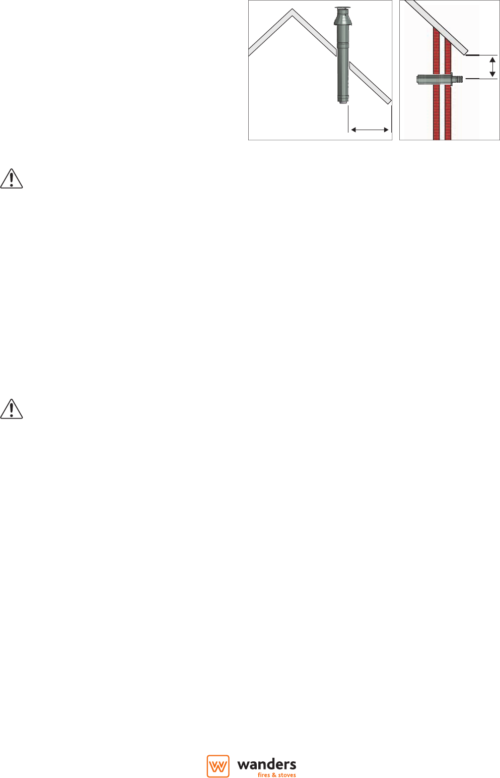
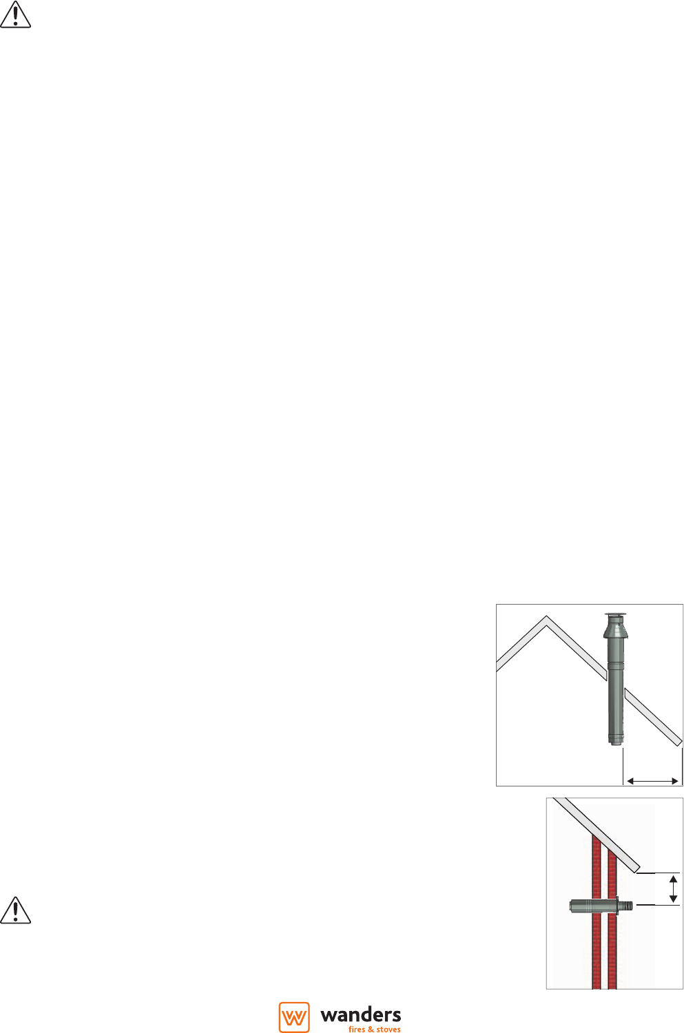
Voorschriften voor het plaatsen van de uitmonding 10
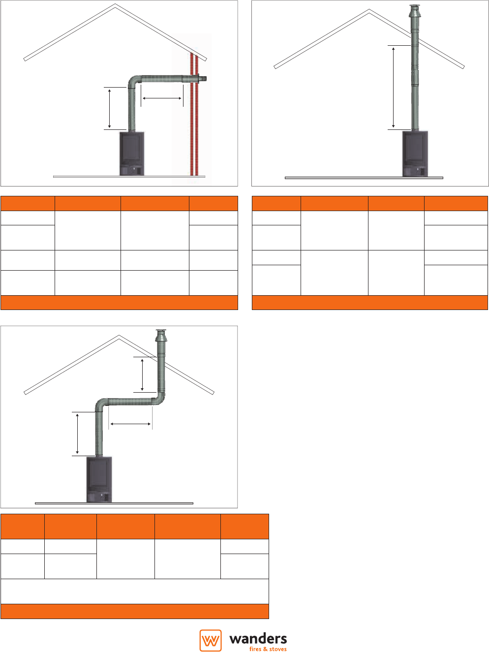
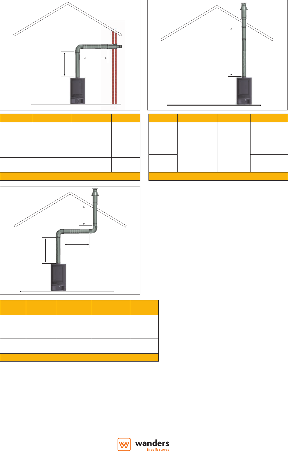
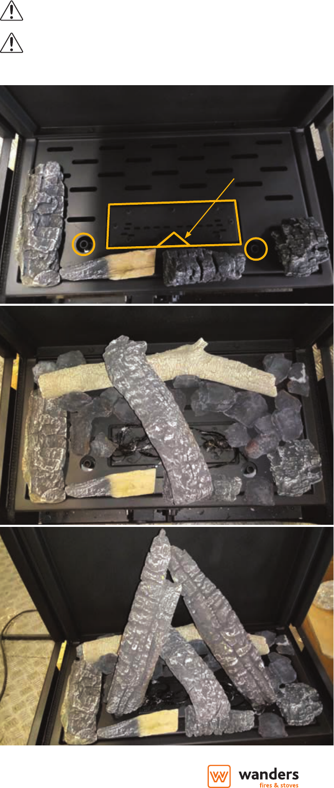
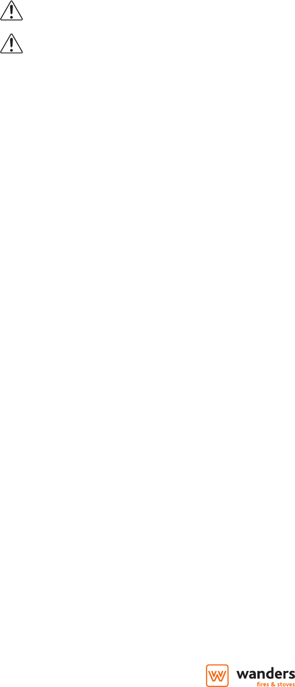
Opstellingsmogelijkheden kanalensysteem 11
Geveldoorvoer (type C11) 11
Dakdoorvoer (type C31) 11
Eerst het pijpensysteem aanbrengen, dan het toestel plaatsen 13
Openen (en sluiten) van de kachel 13
Het plaatsen van de haard (hangend) 13
Het plaatsen van de haard (staand) 14
Montage stuw 14
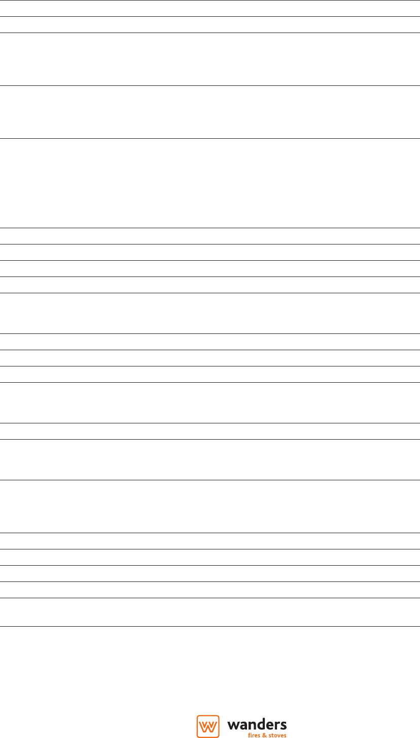
Houtset plaatsen 15
Overzicht houtblokken en decoratie 15
Layout houtset 15
Reparaties 17
Glas vervangen 17
4
NL
Algemeen
Over het algemeen zorgt de dealer waar u uw gashaard heeft aangeschaft, ook voor de installatie ervan en de aansluiting
op het gasnet. Is dat niet het geval, verzeker u er dan van dat de installatie wordt uitgevoerd door een erkende installateur.
Aansluiten van gasinstallaties door onbevoegden is verboden. Wij kunnen u in dat geval geen garantie geven op de juiste
werking van de gaskachel.
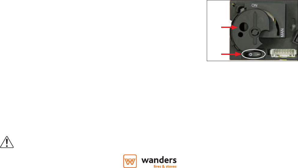
Locatie bediening en ontvanger
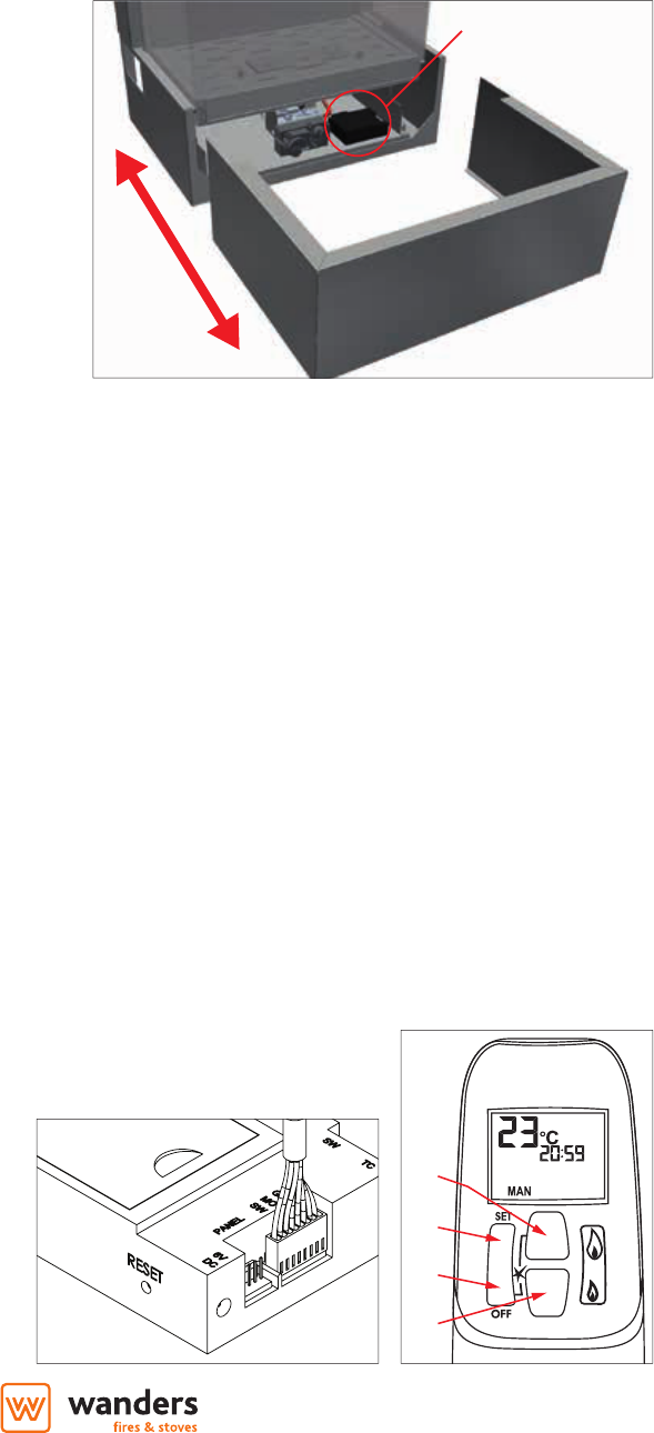
Om bij de bedieningselementen en de ontvanger te komen
dient u volgende stappen te volgen;
• pak de het onderste frame aan de zijkant vast,
• trek het frame voorzichtig naar u toe.
Hier vindt u het gasregelblok (type Mertik GV60-M1 C5D3KL)
en de ontvanger (type Mertik GV60-R4AU).
Batterijen (standaard)
De batterijen van de afstandsbediening en ontvanger
hebben een levensduur van ongeveer één jaar. Gebruik
van alkaline batterijen wordt aanbevolen. Vervangen is
noodzakelijk wanneer bij de afstandsbediening de LED
auwer begint te branden en het woord “BATT” in het display verschijnt. Bij de ontvanger zult u middels geluidstonen erop
gewezen worden dat de batterijen vervangen dienen te worden. U hoort, tijdens het ontsteken, gedurende 0,8 seconden een
toon gevolgd door 0,2 seconden rust.
Vervangen van de batterijen van de afstandsbediening
Open het klepje aan de achterzijde van de afstandsbediening (type Mertik G6R-H4TV4). Haal voorzichtig de 9V-blokbatterij
eruit en maak deze los van de contacthouder. Voorkom het trekken aan de kabel. Verbind de nieuwe batterij en plaats het
geheel terug. Sluit het klepje.
Vervangen van de batterijen van de ontvanger
Trek voorzichtig de gehele ontvanger (type Mertik GV60-R4AU) onder uit de kachel. Schuif het klepje open en plaats 4 nieuwe
1,5V-batterijen (type LR6 of AA). Let op dat u de batterijen op de juiste wijze in de ontvanger plaatst. Leg vervolgens de
ontvanger weer in de kachel.
Optionele adapter
Optioneel kunt u op de ontvanger een adapter aansluiten (art.nr. INK.3270). Daarbij komen de batterijen te vervallen en
moeten deze uit de ontvanger verwijderd worden. Bij een eventuele stroomstoring kunt u de haard alsnog gebruiken door
de batterijen te plaatsen.
Instellen van de afstandsbediening
Als de batterijen geplaatst zijn moet de
elektronische code ingesteld worden (alleen bij
eerste ingebruikname) druk de RESET knop op de
ontvanger net zo lang in tot u 2 signalen hoort. Na de
tweede, langere pieptoon, moet u binnen 20 sec de
kleine vlam knop (2) drukken tot u een lang signaal
(2 pieptonen) hoort ter bevestiging dat de code is
ingesteld.
GV60-R4AU
5
NL
Tijd instellen
• Door het gelijktijdig indrukken van de grote vlam knop (1) en de kleine vlam knop (2) zal het display gaan knipperen u bent
nu in de set mode.
• In de set mode kunt u de grote vlam knop (1) indrukken om de uren in te stellen en de kleine vlam knop (2) om de minuten
in te stellen.
• Wacht of druk de OFF (3) knop om terug te keren naar hand bediening.
Omschakelen van ºC/24u naar ºF/12u
• Druk de OFF (3) knop en de kleine vlam knop (2) gelijk-tijdig (2 sec) in om van ºF (en 12 uurs klok) om te schakelen naar ºC (en
24 uurs klok) en omgekeerd.
Mogelijke instellingen
• Door het indrukken van de SET (4) knop kunt u snel omschakelen tussen MAN > dag temperatuur > verlichting >
ventilator > nacht temperatuur > timer > MAN.
• MAN in deze setting kunt u doormiddel van de knoppen grote vlam (1) of kleine vlam (2) handmatig de vlam hoger of lager
instellen
• Dag temperatuur () in deze setting kunt u de gewenste temperatuur overdag instellen de afstandsbediening fungeert
dan als thermostaat.
• Verlichting en ventilator zijn standaard niet in gebruik. Uw installateur kan deze eventueel wel gebruiken. Hiervoor moet
echter een optionele functie-box (type Mertik G6R-BEAV2) worden aangesloten (art.nr. INK.3255).
• Nacht temperatuur () in deze setting kunt u de gewenste nacht temperatuur instellen.
• TIMER in de timer setting kunt 2 inschakel- en 2 uitschakeltijden instellen per 24 uur. Als de nacht instelling op - - - staat zal
de kachel op waakvlam gaan branden.
Instellen van de temperatuur
• Selecteer de dag temperatuur of nacht temperatuur door de SET knop (4) kort in te drukken.
• Druk nu de SET knop (4) langer in tot het display knippert.
• Stel de temperatuur in met de knoppen (1) of (2) (5ºC is de minimum dag temperatuur).
• Wacht of druk de OFF knop (3) om naar thermostaat gestuurde controle te gaan.
• Om de batterijen te sparen adviseren wij om de temperatuur voor de nacht terug te regelen tot u het - - - symbool in de
display ziet.
Instellen van de timer functie
• Selecteer de timer functie door de SET knop (4) enkele malen kort in te drukken.
• Druk de SET knop (4) nu langer in totdat P1 () knippert.
• Stel de uren in met toets (1), de minuten met knop (2).
• Druk de SET knop (4) kort in voor de volgende tijd.
• Als alle 4 tijden ingesteld zijn drukt u op de OFF knop (3) om het instellen te beëindigen.
Bediening (standaard afstandsbediening)
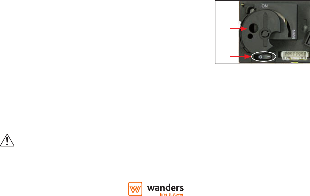
Aansteken van het vuur
• Open de gas afsluitkraan die in de gasleiding naar het toestel is gemonteerd.
• Druk de “O I” schakelaar (5), op het gasregelblok, in de “I” positie.
• Draai de bedieningsknop (6), op het gasregelblok, in de ON positie.
• Druk op de handzender de knoppen (3) en (1) gelijktijdig in. Een kort geluidssignaal
zal de start bevestigen. Daarna zullen korte geluidssignaaltjes (0,2 sec. toon,
1Hz.) volgen totdat de waakvlam en hoofdbrander worden ontstoken. Nadat de
hoofdbrander is ontstoken gaat de vlamhoogte automatisch naar de maximale
stand.
Mogelijke foutmeldingen
• Lange signalen (0,8 sec. toon, 0,2 sec. rust) tijdens de ontsteking > batterijen van de ontvanger zijn bijna leeg. (Nadat dit
signaal optreedt kan men nog ongeveer 10x het toestel inschakelen.)
• 5 Seconden continu signaal > foutmelding. Bijvoorbeeld; één van de kabels is niet verbonden, de “O I” schakelaar staat niet
6
NL
in de “I” positie.
• 5x Kort signaal (0,2 sec. toon, 0,2 sec. rust) > ontsteking van waakvlam en hoofdbrander is niet gelukt. Mogelijke oorzaak lucht
in de waakvlamleiding.
Belangrijk: Gaat de waakvlam uit, dan dient U minimaal 5 MINUTEN te wachten voordat men de bovenstaande
handelingen herhaalt.
Instellen van de vlamhoogte
• Na ontsteking van de brander gaat de vlamhoogte automatisch naar de maximale stand.
• Druk continu op knop (2) om het vlambeeld te verlagen en om de brander uit te schakelen (doven van het vuur: “STAND
BY”). Kort op toets (2) drukken verlaagt het vlambeeld geleidelijk.
• Druk op toets (1) om het vlambeeld te verhogen. Kort op toets (1) drukken verhoogt het vlambeeld geleidelijk.
• Druk knop (4) en knop (2) gelijktijdig in om de achterste brander uit te schakelen.
• Druk knop (4) en knop (1) gelijktijdig in om de achterste brander weer in te schakelen.
• Het is niet mogelijk om alleen de achterste brander te laten branden.
Uitschakelen van het toestel
• Druk op toets (2) om het vlambeeld te verlagen en om de brander uit te schakelen.
• Druk daarna op de “OFF” knop (3) om het gehele toestel, inclusief de waakvlam, uit te schakelen.
• Wordt het toestel langere tijd niet gebruikt, dan is het aan te bevelen om de gas afsluitkraan in de toevoerleiding dicht te
draaien.
Belangrijk: Wanneer door welke oorzaak dan ook de waakvlam dooft, 5 MINUTEN wachten alvorens de
waakvlam opnieuw aan te steken.
Gas besparend systeem
De elektronica van uw haard is geprogrammeerd om gas te besparen als de haard niet gebruikt wordt. Indien de ontvanger 3
uur geen signaal ontvangt van de afstandsbediening zal deze terugschakelen naar de waakvlam. Is er na 5 dagen nog steeds
geen signaal ontvangen zal de haard zich volledig uitschakelen. U kunt dit voorkomen door de timer functie te programmeren
waarmee regelmatig een signaal verstuurd wordt.
Storing
Als blijkt dat de signalen van de afstandsbediening niet goed bij de kachel (ontvanger) aankomen, kan dit veroorzaakt worden door:
• Lege batterijen: batterijen vervangen.
• Een elektronisch probleem: oplossen door een ‘harde reset’ uit te voeren. Hiervoor dient men de stroom van de ontvanger
af te halen (batterijen verwijderen of adapter afkoppelen). Vervolgens de “RESET” knop op de ontvanger 8 seconden in
drukken. Stroom weer op de ontvanger zetten en de kachel herstarten.
• Indien het toestel zich regelmatig uitschakelt dient u kontact met uw installateur op te nemen.
Bediening (afstandsbediening met EcoWave)
Voor de volledige uitleg van de bediening middels de SYMAX afstandsbediening verwijzen wij naar de separaat bijgeleverde
handleiding.
Bediening (optionele Wanders Eco Wave app)
Om de haard te bedienen met de Wanders Eco Wave app is het mogelijk de optionele WiFi module bij te bestellen.
De app is gratis te downloaden in de Apple App Store en/of de Google Play Store. Overigens kan de app alleen gebruikt
worden i.c.m. de SYMAX EcoWave afstandsbediening.
7
NL
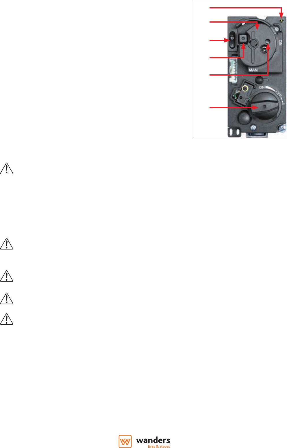
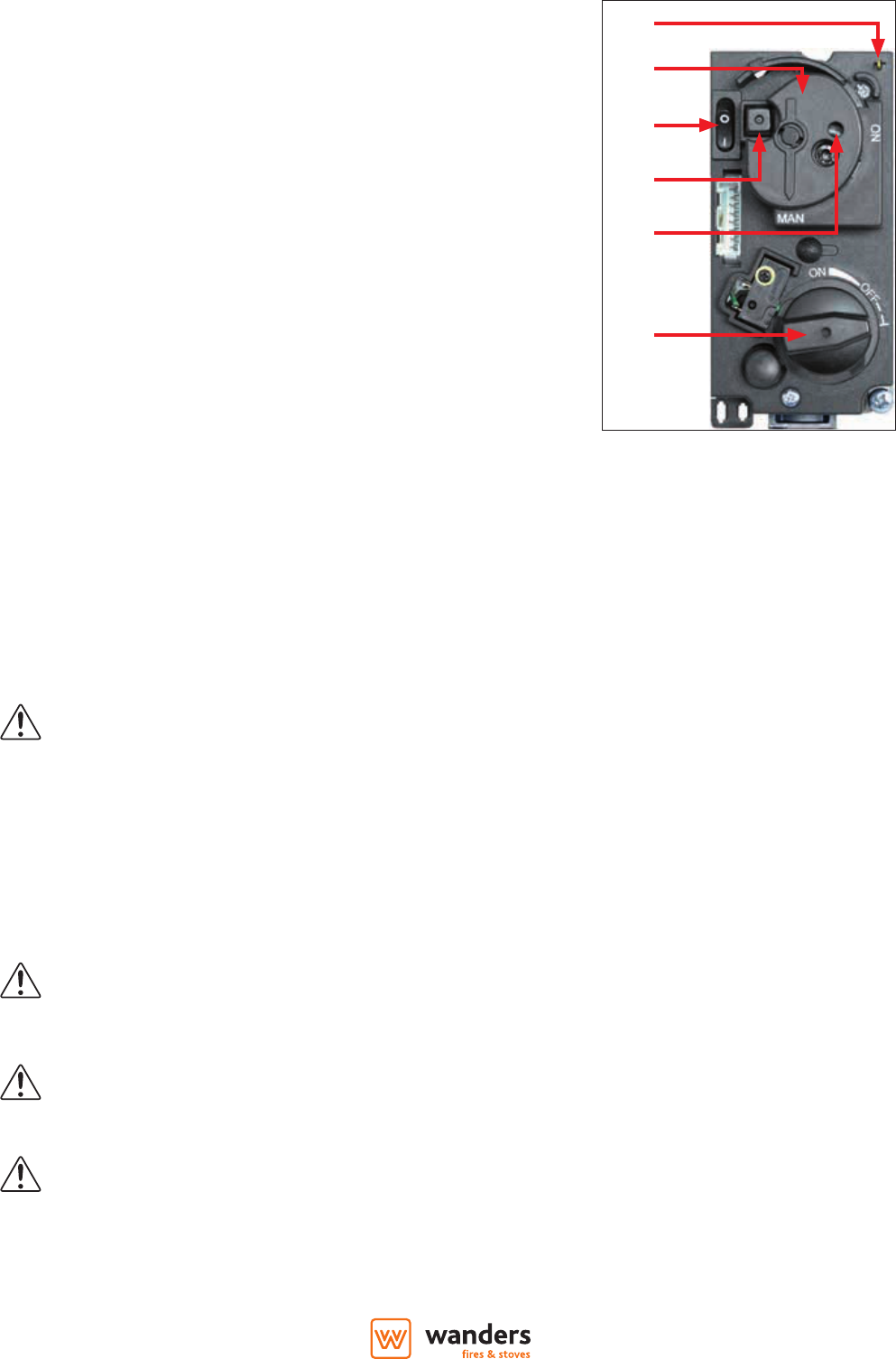
Bediening (handbediening)
Als de batterijen leeg zijn of in geval dat de ontvanger defect is kan men de kachel ook met de hand bedienen. Hiervoor moet
eerst de ontsteek (piëzo) kabel van de ontvanger worden ontkoppelt en die voorzichtig op de piëzo aansluiting (10) van het
gasregelblok worden geschoven.
Aansteken en uitschakelen van het vuur
1. Open de gas afsluitkraan die in de gasleiding naar het toestel is gemonteerd.
2. Druk de “O I” schakelaar (5), op het gasregelblok, in de “I” positie.
3. Draai de motorknop (7), op het gasregelblok, geheel rechtsom. De knop maakt
hierbij een tikkend geluid.
4. Draai de bedieningsknop (6), op het gasregelblok, in de MAN positie in de
bedieningsknop wordt nu een opening zichtbaar (8).
5. Druk bijvoorbeeld met een pen in de opening het metalen pennetje in. Er
stroomt nu gas naar de waakvlam.
6. Terwijl men het metalen pennetje ingedrukt houdt, dient men enkele malen
de (vierkante) ontsteekknop (9) (naast de “O I” schakelaar) in te drukken om
de waakvlam te ontsteken. Door het glasraam kan men zien of de waakvlam
brandt.
7. Als de waakvlam brandt, het metalen pennetje nog 10 seconden ingedrukt
houden en daarna loslaten. Gaat de waakvlam uit dan dient u minimaal 5
minuten te wachten voordat u de bovenstaande stappen herhaalt.
8. Draai de bedieningsknop (6) naar de “ON” positie.
9. Door de motorknop (7) linksom te draaien kan men de brander ontsteken en
kan men de juiste vlamhoogte kiezen.
10. Om het vuur te doven de motorknop (7) geheel rechtsom draaien, de waakvlam
blijft branden
11. Om ook de waakvlam te doven moet u de “O I” schakelaar op “O” zetten.
12. Gaskraan sluiten.
Eerste keer stoken
Wanneer u uw gaskachel voor de eerste keer gebruikt, moet de haard ‘instoken’. Het toestel is voorzien van een hittebestendige
laklaag die nog moet inbranden in de kachel. Dat kan een vervelende geur met zich meebrengen, maar is verder onschadelijk.
We raden u aan de kachel circa drie uur te stoken op de hoogste stand waarbij u de ruimte goed ventileert.
Verkleuren van wanden, plafonds en roosters
Na het stoken van de haard kunnen wanden, plafonds en roosters verkleuren. Dit komt doordat stofdeeltjes
verbranden in de convectiemantel. Dit is een natuurlijk proces waar WANDERS niet verantwoordelijk voor is.
Om verkleuring te minimaliseren verwijzen wij naar het advies dat gegeven wordt in de sfeerhaardenbranche.
Uw installateur kan u hierover informeren.
Tijdens het instoken kan er aanslag komen op het keramische glas van de kacheldeur. Deze aanslag verwijdert u als het
glas koud is eenvoudig met een licht vochtige doek. Eventueel gebruikt u speciaal schoonmaakmiddel voor keramische
kookplaten. Op pagina 13 wordt beschreven hoe u het glas verwijderd.
Let op vingerafdrukken
Pas op dat u het gereinigde glas niet meer met de vingers aanraakt wanneer u de kacheldeur sluit.
Vingerafdrukken branden in het glas.
Let erop dat er geen houtblokken voor de waakvlam liggen. Het gas moet vrijelijk naar de hoofdbrander kunnen
stromen. De hoofdbrander bevindt zich onder de houtset. Voor een juiste opstelling van de keramische houtset,
zie pag 15 en verder.
8
NL
Het is raadzaam in het stookseizoen de waakvlam te laten branden. Dat voorkomt eventuele condensvorming
en mogelijk kalksporen aan de binnenzijde van de deur.
Nieuwbouwwoning of recente renovatie?
Wacht zes weken met stoken in een nieuwbouwwoning die recent is opgeleverd, of een ruimte die onlangs
sterk is gerenoveerd. In muren en plafonds zitten dan nog gassen, weekmakers en vocht afkomstig van stuc- en
schilderwerk. Door de warme luchtstromen, kunnen de vele stofdeeltjes in de ruimte verkleuren en vastplakken
aan wanden en plafonds. Ook het vocht in de muren en plafonds wordt warm, wat gele vlekken kan veroorzaken.
Onderhoud
Klein onderhoud
Voorkom te veel stof en deeltjes van tabaksrook, kaarsen en olielampen in de lucht van uw woning. Verhitting van deze deeltjes,
via het convectie systeem kan leiden tot verkleuring van wanden en plafond. Daarom dient men het vertrek waar het toestel
staat altijd voldoende te ventileren. Verwijder regelmatig de eventuele aanslag achter de deur met een stofzuiger. Indien men
op het toestel morst dient het onmiddellijk uitgezet te worden. Pas als het toestel is afgekoeld kan men het reinigen.
Gebruik geen agressieve schoonmaak- en schuurmiddelen en geen kachelpoets.
Jaarlijks onderhoud
Uw gashaard moet minimaal één keer per jaar worden gecontroleerd en onderhouden door een erkend installateur. De
volgende onderdelen worden dan nagekeken:
• De dichtheid van de gas- en rookgasafvoer en de verbrandingsluchttoevoer.
• De juiste werking van het gasregelblok, het thermokoppelcircuit (beveiliging tegen onverwachte gasuitstroom) en het
ontsteken van de hoofdbrander.
• Het volledige kanalensysteem, inclusief de gevel- of dakdoorvoer en de uitmonding net daarbuiten.
• Eventuele slijtage van afdichtingen van deuren en glasramen.
• Schoongemaakt worden: de hoofdbrander, de waakvlam, de rookgasafvoer en de toevoer van de verbrandingslucht. Stof in
de kachel kan met een stofzuiger schoongemaakt worden.
Veiligheid
Een warmtebron van WANDERS, is meer dan alleen de haard in uw kamer. Ook het rookkanaal en de dak- en/of geveldoorvoer
maken deel uit van het verwarmingssysteem. Alleen als uw gashaard is geïnstalleerd met het concentrische rookkanaal van
WANDERS, kunnen wij u garanderen dat de kachel veilig brandt.
Elke gashaard van WANDERS is voorzien van een thermokoppelbeveiliging. Dit voorkomt dat gas vrij uitstroomt als de
waakvlam is uitgevallen.
Een aantal aanbevelingen voor een veilig gebruik van uw gaskachel:
• Stook uw gashaard alleen als hij goed gesloten is. Als het glas is gebroken, mag u de kachel niet gebruiken.
• Voorkom dat kleine kinderen of hulpbehoevenden in de buurt van een brandende kachel komen en laat ze niet alleen als de
haard brandt. Gebruik eventueel een haardscherm.
• Laat kinderen nooit spelen met de afstandsbediening.
• Giet of leg geen brandbare vloeistoen en materialen op de houtset. Dit kan de kachel onherstelbaar beschadigen.
• Plaats geen brandbare materialen, bijvoorbeeld gordijnen, vlakbij de haard. Houd minimaal een afstand van 1,5 meter aan.
• De gashaard mag alleen gerepareerd worden met originele onderdelen en door een erkend installateur.
• Mocht om welke reden dan ook de waakvlam uitvallen, wacht dan vijf minuten voordat u de kachel weer ontsteekt.
9
NL
Mogelijke foutmeldingen
Mocht uw gashaard niet naar wens functioneren, neem dan contact op met de verkoper van uw gaskachel of een erkend
installateur. Mocht de waakvlam niet aanslaan, dan kunt u zelf actie ondernemen.
• Controleer of de gastoevoer open staat. Mocht u deze niet kunnen vinden, neem dan contact op met uw installateur.
• Mogelijke oorzaak is lucht in de waakvlamleiding. Wacht vijf minuten en ontsteek de kachel opnieuw. Lukt dit opnieuw niet,
schakel dan een erkend installateur in.
• Als de batterijen van de ontvanger bijna leeg zijn zullen er 3 acoustische signalen te horen zijn. Verwissel dan de batterijen
in de ontvanger.
• Indien u een lange pieptoon hoort staat de O/I knop op het gasblok in de O positie. Zet deze dan op I.
• Een tweede mogelijkheid bij de lange pieptoon kan een verbindingsfout zijn tussen de ontvanger en de afstandsbediening.
Regel de afstandsbediening opnieuw in zoals beschreven op pagina 4.
Garantie
Op uw gaskachel biedt WANDERS Metaalproducten B.V. te Netterden een garantie van 1 jaar na aankoopdatum, mits de haard
op de juiste wijze is geïnstalleerd en wordt gebruikt volgens de aanwijzingen in deze handleiding. Onder de garantie vallen
alle gebreken die te herleiden zijn tot materiaal- en constructiefouten. In die gevallen ontvangt u gratis nieuwe onderdelen.
Arbeidsloon en andere kosten vallen niet onder de garantie. Defecte onderdelen kunt u franco toezenden aan WANDERS
Gebruikershandleiding.com neemt misbruik van zijn services uitermate serieus. U kunt hieronder aangeven waarom deze vraag ongepast is. Wij controleren de vraag en zonodig wordt deze verwijderd.
Product:
Spelregels forum
Om tot zinvolle vragen te komen hanteren wij de volgende spelregels:
lees eerst de handleiding door;
controleer of uw vraag al eerder door iemand anders is gesteld;
probeer uw vraag zo duidelijk mogelijk te stellen;
heeft u een probleem en al geprobeerd om dit op te lossen, vermeld dit erbij aub;
heeft u een oplossing gekregen van een bezoeker dan horen wij dat graag in dit forum;
wilt u een reactie geven op een vraag of antwoord, gebruik dan niet dit formulier maar klik op de knop 'reageer op deze vraag';
uw vraag wordt direct op de website gezet; vermijd daarom persoonlijke gegevens in te vullen;
Belangrijk! Als er een antwoord wordt gegeven op uw vraag, dan is het voor de gever van het antwoord nuttig om te weten als u er wel (of niet) mee geholpen bent! Wij vragen u dus ook te reageren op een antwoord.
Belangrijk! Antwoorden worden ook per e-mail naar abonnees gestuurd. Laat uw emailadres achter op deze site, zodat u op de hoogte blijft. U krijgt dan ook andere vragen en antwoorden te zien.
Abonneren
Abonneer u voor het ontvangen van emails voor uw Wanders Larix bij:
nieuwe vragen en antwoorden
nieuwe handleidingen
U ontvangt een email met instructies om u voor één of beide opties in te schrijven.
Ontvang uw handleiding per email
Vul uw emailadres in en ontvang de handleiding van Wanders Larix in de taal/talen: Nederlands, Duits, Engels, Frans als bijlage per email.
De handleiding is 6,12 mb groot.
U ontvangt de handleiding per email binnen enkele minuten. Als u geen email heeft ontvangen, dan heeft u waarschijnlijk een verkeerd emailadres ingevuld of is uw mailbox te vol. Daarnaast kan het zijn dat uw internetprovider een maximum heeft aan de grootte per email. Omdat hier een handleiding wordt meegestuurd, kan het voorkomen dat de email groter is dan toegestaan bij uw provider.
Stel vragen via chat aan uw handleiding
Stel uw vraag over deze PDF
Uw handleiding is per email verstuurd. Controleer uw email
Als u niet binnen een kwartier uw email met handleiding ontvangen heeft, kan het zijn dat u een verkeerd emailadres heeft ingevuld of dat uw emailprovider een maximum grootte per email heeft ingesteld die kleiner is dan de grootte van de handleiding.
Er is een email naar u verstuurd om uw inschrijving definitief te maken.
Controleer uw email en volg de aanwijzingen op om uw inschrijving definitief te maken
U heeft geen emailadres opgegeven
Als u de handleiding per email wilt ontvangen, vul dan een geldig emailadres in.
Uw vraag is op deze pagina toegevoegd
Wilt u een email ontvangen bij een antwoord en/of nieuwe vragen? Vul dan hier uw emailadres in.