484377
3
Verklein
Vergroot
Pagina terug
1/226
Pagina verder
2006
C70 INSTR.indd 1C70 INSTR.indd 1 05-07-07 10.51.3805-07-07 10.51.38
VOLVO
OWNERS MANUAL
C70
WEB EDITION
1
Dear Volvo owner
We hope you will enjoy many years of driving pleasure in your Volvo. The car has been designed for the safety and comfort of you and your
passengers. Volvo is one of the safest cars in the world. Your Volvo has also been designed to satisfy all current safety and environmental
requirements.
In order to increase your enjoyment of the car, we recommend that you familiarise yourself with the equipment, instructions and maintenance
information contained in this owner’s manual.
Thank you for choosing Volvo!
C70 w540.book Page 1 Monday, July 18, 2005 4:25 PM
2
Introduction
Owner’s Manual
A good way of getting to know your new car
is to read the owner’s manual, ideally before
your first journey. This will give you the oppor-
tunity to familiarise yourself with new
functions, to see how best to handle the car
in different situations, and to make the best
use of all the car’s features. Please pay
attention to the safety instructions contained
in the manual:
The equipment described in the owner’s
manual is not present in all models. In
addition to standard equipment, this manual
also describes options (factory fitted
equipment) and certain accessories (extra
equipment).
NOTE! Volvo cars are adapted for the varying
requirements of different markets, as well as
for national or local legal requirements and
regulations.
The specifications, design features and illus-
trations in this owner’s manual are not
binding. We reserve the right to make modifi-
cations without prior notice.
© Volvo Car Corporation
WARNING!
"Warning!" texts indicate where there is a
risk of personal injury in the event of the
instructions not being followed.
IMPORTANT!
"Important!" texts indicate a risk of
damage to the car in the event of the
instructions not being followed.
C70 w540.book Page 2 Monday, July 18, 2005 4:25 PM
3
Volvo Car Corporation and the environment
Volvo Cars’ environmental
philosophy
Environmental care, safety and quality are the
three core values which influence all opera-
tions of the Volvo Car Corporation. We also
believe that our customers share our consid-
eration for the environment.
Your Volvo complies with strict international
environmental standards and is also
manufactured in one of the cleanest and most
resource-efficient plants in the world. Volvo
Car Corporation has global certification to
the ISO 14001 environmental standard,
which leads to continuous improvements
within the area of the environment.
EPI (Environmental Product Information)
environmental product declarations are
supplied for all Volvo models. You can now
compare the environmental impact of
different models and engines.
Read more at www.volvocars.com/EPI
Fuel consumption
Volvo cars have competitive fuel
consumption in each of their respective
classes. Lower fuel consumption generally
results in lower emission of the greenhouse
gas, carbon dioxide.
It is possible for the driver to influence fuel
consumption, see page 4.
Efficient emission control
Your Volvo is manufactured following the
concept
Clean inside and out
– a concept
that encompasses a clean interior
environment as well as highly efficient
emission control. In many cases the exhaust
emissions are well below the applicable
standards.
In addition there is a special radiator coating,
PremAir
®1
, which can convert hazardous
ground-level ozone into pure oxygen.
1. Option for 5-cylinder engines.
PremAir
®
is a registered trademark of
Engelhard Corporation.
C70 w540.book Page 3 Monday, July 18, 2005 4:25 PM
4
Volvo Car Corporation and the environment
Clean air in the passenger
compartment
A sophisticated air cleaning system, IAQS
1
(Interior Air Quality System) ensures that the
air in the passenger compartment is cleaner
than the air in the traffic outside.
The system consists of an electronic sensor
and a carbon filter. The air intake is closed if
there is an increase in the level of reducing
gases and oxidising gases, e.g. carbon
monoxide, for example in heavy traffic,
queues and tunnels. The entry of nitrous
oxides, ground-level ozone and hydrocarbons
is prevented by the carbon filter.
Textile standard
The interior of a Volvo is designed to be
healthy and safe - even for people with
contact allergies and for asthma sufferers.
Extreme attention has been given to choosing
environmentally-compatible materials. This
means that they also fulfil the requirements of
the Öko-Tex 100 ecological standard - a
major advance towards a healthier passenger
compartment environment.
Öko-Tex certification covers seatbelts,
carpets, thread and fabrics for example. Even
the leather upholstery undergoes chromium-
free tanning with natural plant substances
and meets the requirements.
Volvo workshops and the
environment
Regular maintenance creates the conditions
for long service life for the car and low fuel
consumption, and contributes to a cleaner
environment. When Volvo’s workshops are
entrusted with the repair and maintenance of
the car, it becomes part of our system. We
make clear demands regarding the way in
which our workshops are designed in order
to prevent spills and discharges into the
environment. Our workshop staff have the
knowledge and the tools required to
guarantee good environmental care.
Reducing environmental impact
You can help reduce environmental impact,
for example, by purchasing eco-labelled car
care products and by servicing and
maintaining the car according to the instruc-
tions in the owner’s manual.
The following hints will help you to do your bit
for the environment:
Ensure that your tyre pressures are
correct. Poorly inflated tyres increase fuel
consumption. If any of the higher tyre
pressures recommended by Volvo are
used then fuel consumption decreases.
Remove unnecessary items from the car -
the greater the load the higher the fuel
consumption.
Is your car equipped with an engine block
heater? If so, use it for a few hours before
starting from cold to reduce fuel
consumption and exhaust emissions.
Drive gently! Avoid unnecessary acceler-
ation and braking too hard.
Drive in the highest gear
possible. Low engine
speeds result in lower
fuel consumption.
Ease back on the accel-
erator on downhill
gradients.
Use engine braking. Take your foot off the
accelerator and change down.
Avoid idling. Switch off the engine in
traffic queues.
1. Option.
C70 w540.book Page 4 Monday, July 18, 2005 4:25 PM
5
Volvo Car Corporation and the environment
Always dispose of
environmentally
hazardous waste, such
as batteries and oils, in
an environmentally safe
manner. If uncertain
about disposal, consult an authorised
Volvo workshop for advice.
Service your car regularly.
These hints will help you to reduce your fuel
consumption without increasing your travel
time or lessening the enjoyment of driving.
Apart from being kind to your car, you’ll be
saving money - and the Earth’s resources.
C70 w540.book Page 5 Monday, July 18, 2005 4:25 PM
6
C70 w540.book Page 6 Monday, July 18, 2005 4:25 PM
7
Contents
Safety 9
Instruments and controls 33
Climate control 61
Interior 71
Locks and alarm 89
Starting and driving 101
Wheels and tyres 133
Car care 149
Maintenance and service 155
Infotainment system 181
Technical data 203
C70 w540.book Page 7 Monday, July 18, 2005 4:25 PM
8
C70 w540.book Page 8 Monday, July 18, 2005 4:25 PM
9
Safety
Seatbelts 10
Airbag system 13
Airbags (SRS) 14
Airbag (SRS) on the driver’s side 15
Activating/deactivating the airbag (SRS) 17
Side airbags (SIPS bags) 19
Inflatable Curtain (DMIC) 21
WHIPS 22
Roll-Over Protection System (ROPS) 24
When are the safety systems activated? 25
Crash mode 26
Inspecting the airbags and inflatable curtains 27
Child safety 28
C70 02 Safety w540.fm Page 9 Monday, August 1, 2005 9:29 AM
10
Safety
Seatbelts
Tensioning the hip strap. The belt must be
positioned low down.
Always use a seatbelt
Heavy braking can have serious conse-
quences if the seatbelts are not used. Ensure
that all passengers use their seatbelts.
Otherwise, rear seat passengers may be
thrown forward against the backs of the front
seats in an accident.
Putting on a seatbelt:
Pull the belt out slowly and secure it by
pressing the buckle into the lock. A loud
"click" indicates that the belt has locked.
Releasing the belt:
Press the red lock button and let the belt
retract. If the belt does not retract fully,
feed the belt in by hand so that it does not
hang loose.
The belt locks and cannot be withdrawn:
if it is pulled out too quickly
during braking and acceleration
if the car leans heavily.
It is important that the belt lies against the
body so it can provide maximum protection.
Do not lean the backrest too far back. The
seatbelt is designed to protect in a normal
seating position.
Keep the following in mind:
do not use clips or anything else that can
prevent the belt from fitting properly
ensure the belt is not twisted or caught
on anything
the hip strap must be positioned low
down (not over the abdomen)
tension the hip strap over the lap by
pulling the diagonal shoulder belt as
illustrated.
WARNING!
Each belt is intended for one person only.
WARNING!
The seatbelts and airbags interact. If a
seatbelt is not used or is used incorrectly,
this may diminish the protection provided
by the airbag in the event of a collision.
WARNING!
Never modify or repair the seatbelts
yourself. Contact an authorised Volvo
workshop.
If the belt has been subjected to a major
load, such as in a collision, the entire belt
must be replaced. This includes the reel,
mountings, bolts and buckles. Some of
the protective characteristics of the belt
may have been lost, even if it appears to
be undamaged. In addition, replace the
seatbelt if the belt is worn or damaged.
The new seatbelt must be type-approved
and intended for installation in the same
position as the replaced belt.
C70 w540.book Page 10 Monday, July 18, 2005 4:25 PM
11
Safety
Seatbelts
Seatbelt reminder
Unbelted occupants will be reminded to
fasten their seatbelts through an audio and
visual reminder. The audio reminder is speed-
dependent. The visual reminder is located in
the roof console and the combined
instrument panel. At low speed, the audio
reminder will sound for the first six seconds.
The seatbelt reminder system does not cover
child seats installed on the front passenger
seat using the seatbelt.
Rear seat
The seatbelt reminder in the rear seat has two
subfunctions:
Provides information on which seatbelts
are being used in the rear seat (shown on
the information display). The message is
automatically cleared after approx.
30 seconds or can be acknowledged
manually by pressing the READ button.
Provides a warning if one of the rear
seatbelts is unfastened during travel. This
warning takes the form of a message on
the information display along with the
audio/visual signal. The warning ceases
when the seatbelt is re-fastened or when
manually acknowledged by pressing the
READ button.
The message on the information display
showing which belts are in use is always
available. Press the READ button to see
stored messages.
Certain markets
An unbelted driver will be reminded to fasten
his or her seatbelt through an audio and
visual reminder. At low speed, the audio
reminder will sound for the first six seconds.
Seatbelts and pregnancy
The seatbelt should always be worn during
pregnancy. But it is crucial that it be worn in
the correct way. The diagonal section should
wrap over the shoulder then be routed
between the breasts and to the side of the
belly. The lap section should lay flat over the
thighs and as low as possible under the
abdomen. It must never be allowed to ride
upward. Remove all slack from the belt and
ensure that it fits close to the body without
any twists.
As the pregnancy progresses, pregnant
drivers should adjust their seats and steering
wheel such that they can easily maintain
control of the vehicle as they drive (which
C70 w540.book Page 11 Monday, July 18, 2005 4:25 PM
12
Safety
Seatbelts
means they must be able to easily operate the
foot pedals and steering wheel). Within this
context, they should strive to position the seat
with as large a distance as possible between
their belly and the steering wheel.
Label on seatbelts with seatbelt tensioner.
Seatbelt tensioner
All the seatbelts are equipped with belt
tensioners. A mechanism in the belt tensioner
tightens the belt around the body in the event
of a sufficiently forceful collision. This
provides more effective restraint for
passengers.
There is a belt guide for both driver's and
passenger seats.
Belt guide
The belt guide is designed to improve access
with the seatbelt. When stepping into and out
of the rear seat the seatbelt must be taken
from the belt guide and put furthest back on
the seatbelt bar.
C70 w540.book Page 12 Monday, July 18, 2005 4:25 PM
13
Safety
Airbag system
Warning symbol on the
combined instrument panel
The AIRBAG system
1
is continually
monitored by the system control module. The
warning symbol on the combined instrument
panel illuminates when the ignition key is
turned to position I, II or III. The symbol goes
out after approx. seven seconds provided the
airbag system
1
is fault-free.
As well as the warning
symbol, a message appears
on the information display. If
the warning symbol malfunc-
tions, the warning triangle
comes on and the message
SRS AIRBAG SERVICE
URGENT appears on the
display. Contact an
authorised Volvo workshop
immediately.
1. Includes SRS and seatbelt tensioner,
SIPS, DMIC and ROPS.
WARNING!
If the warning symbol for the AIRBAG
system remains on or comes on while
driving, it means that the AIRBAG system
is not functioning fully. The symbol can
indicate a fault in the seatbelt buckle,
SIPS, SRS or DMIC systems. Contact an
authorised Volvo workshop immediately.
C70 w540.book Page 13 Monday, July 18, 2005 4:25 PM
14
Safety
Airbags (SRS)
Airbag (SRS) on the driver’s side
The car has an SRS airbag (Supplementary
Restraint System) in the steering wheel to
supplement the protection afforded by the
seatbelt. This airbag is fitted into the centre of
the steering wheel. The steering wheel is
marked SRS AIRBAG.
Passenger airbag (SRS)
The passenger airbag
1
is fitted behind a
panel above the glovebox. This panel is
marked SRS AIRBAG.
WARNING!
The seatbelts and airbags interact. If a
seatbelt is not used or is used incorrectly,
this may diminish the protection provided
by the airbag in the event of a collision.
1. Not all cars have a passenger airbag
(SRS). This can be deselected when
the car is ordered.
WARNING!
To minimise the risk of injury if the airbag
deploys, passengers must sit as upright
as possible with their feet on the floor and
backs against the backrest. Seatbelts
must be secured.
WARNING!
Never place a child in a child seat or on a
booster cushion in the front seat if the
airbag (SRS) is activated
1
.
Never allow a child to stand or sit in front
of the front passenger seat. No one
shorter than 140 cm should sit in the front
passenger seat if the airbag (SRS) is
activated.
Failure to follow the advice given above
can endanger the life of the child.
1. For information on activated/deacti-
vated airbag (SRS) see page 17.
C70 w540.book Page 14 Monday, July 18, 2005 4:25 PM
15
Safety
Airbag (SRS) on the driver’s side
SRS system, left-hand drive.
SRS system
The airbag is equipped with a gas generator.
A sufficiently violent collision trips sensors
and ignites the gas generator, inflating the
airbag with hot gas. To cushion the impact,
the airbag deflates when compressed. When
this occurs, smoke escapes into the car. This
is completely normal. The entire process,
including inflation and deflation of the airbag,
occurs within tenths of a second.
SRS system, right-hand drive.
NOTE! The sensors react differently
depending on the course of the collision and
whether the seatbelts on the driver and
passenger side are used. It is therefore
possible that only one (or none) of the
airbags may inflate in a collision. The SRS
system senses the force of the collision on
the car and adapts accordingly so that only
the required airbag is deployed.
NOTE! The airbags have a function whereby
their capacities adapt to the collision force to
which the vehicle is subjected.
WARNING!
Repairs must only be performed by an
authorised Volvo workshop.
Work on the SRS system can cause
malfunction and result in serious personal
injury.
C70 02 Safety w540.fm Page 15 Monday, August 1, 2005 9:29 AM
16
Safety
Airbag (SRS) on the driver’s side
Location of the passenger airbag in left-hand
drive and right-hand drive cars.
WARNING!
Never interfere with SRS components in
the steering wheel or the panel above the
glovebox.
Objects and accessories must not be
positioned or glued on or near the SRS
AIRBAG panel (above the glovebox) or in
the area affected by a deployed airbag.
C70 02 Safety w540.fm Page 16 Friday, October 21, 2005 9:31 AM
17
Safety
Activating/deactivating the airbag (SRS)
Indicator showing that the passenger airbag
(SRS) is deactivated.
PACOS (option)
The airbag (SRS) for the front passenger
seat can be deactivated using a switch. This
is necessary if a child seat is to be fitted there
for example.
Indicator
A text message on the roof panel indicates
that the passenger airbag (SRS) is deacti-
vated.
Switch for PACOS (Passenger Airbag Cut
Off Switch).
Activating/deactivating
The switch is located on the passenger end
of the dashboard and is accessible when the
passenger door is open. Check that the
switch is in the required position. Volvo
recommends that that the ignition key be
used to change position. (Other items with a
shape similar to a key can also be used.)
WARNING!
If the car is equipped with a front
passenger airbag (SRS), but does not
have PACOS, the airbag will always be
activated.
WARNING!
Activated airbag (passenger seat):
Never place a child in a child seat or on a
booster cushion in the front passenger
seat when the airbag is activated. This
also applies to anyone shorter than
140 cm.
Deactivated airbag (passenger seat):
No one taller than 140 cm should sit in the
front passenger seat when the airbag is
deactivated.
Failure to follow the advice given above
can endanger life.
C70 w540.book Page 17 Monday, July 18, 2005 4:25 PM
18
Safety
Activating/deactivating the airbag (SRS)
Switch for SRS in ON position.
Switch position
ON = Airbag (SRS) activated. With the
switch in this position, persons taller than
140 cm can sit in the front passenger seat,
but never children in a child seat or on a
booster cushion.
Switch for SRS in OFF position.
OFF = Airbag (SRS) is deactivated. With the
switch in this position, children in a child seat
or on a booster cushion can sit in the front
passenger seat, but never persons taller
than 140 cm.
WARNING!
Do not allow anyone to sit in the front
passenger seat if the text message in the
roof panel indicates that the airbag (SRS)
is deactivated and if the warning symbol
for the AIRBAG system is also displayed
on the combined instrument panel. This
indicates that there has been a severe
malfunction. Contact an authorised Volvo
workshop as soon as possible.
C70 w540.book Page 18 Monday, July 18, 2005 4:25 PM
19
Safety
Side airbags (SIPS bags)
Side airbag locations.
Side airbags – SIPS bags
A large proportion of the collision force is
transferred by the SIPS (Side Impact
Protection System) to beams, pillars, the floor
and other structural parts of the body. The
side airbags at the driver’s and front
passenger seats protect the chest area and
the pelvis, and are an important part of the
SIPS. The side airbags are located in the
front seat backrests.
Inflated side airbag.
Child seats and side airbags
The side airbag does not diminish the
protection provided by the car to children
seated in a child seat or on a booster
cushion.
A child seat or booster cushion can be
placed on the front passenger seat provided
that the car does not have an activated
1
passenger airbag.
WARNING!
Side airbags are a supplement to the
SIPS system. Always wear a seatbelt.
WARNING!
Repairs must only be performed by an
authorised Volvo workshop.
Work on the SIPS system can cause
malfunction and result in serious personal
injury.
WARNING!
Do not put objects in the area between
the outside of the seat and the door panel,
since this area is required by the side
airbag.
WARNING!
Use only Volvo genuine car seat covers, or
seat covers approved by Volvo. Other
seat covers may impede the operation of
the side air bags.
1. For information on activated/deacti-
vated airbag (SRS) see page 17.
C70 w540.book Page 19 Monday, July 18, 2005 4:25 PM
20
Safety
Side airbags (SIPS bags)
Left-hand drive.
SIPS bag system
The side airbag is equipped with a gas
generator. A sufficiently violent collision trips
the sensors, which ignite the gas generator,
inflating the side airbag. The airbag inflates
between the occupant and the door panel
and thereby cushions the initial impact while
deflating. The side airbag is only normally
deployed on the side of the collision.
Right-hand drive.
C70 w540.book Page 20 Monday, July 18, 2005 4:25 PM
21
Safety
Inflatable Curtain (DMIC)
Properties
The inflatable curtain DMIC (Door Mounted
Inflatable Curtain) is a supplement to the
SIPS system. It is concealed along the inside
of the driver’s and passenger doors. It only
protects the front seats. The inflatable curtain
is activated by sensors in the event of a suffi-
ciently forceful collision or if the car is at risk
of overturning. When deployed, the inflatable
curtain inflates. The inflatable curtain helps to
prevent the driver and front seat passenger
from striking their heads on the inside of the
car during a collision. The inflatable curtain is
deployed irrespective of whether the roof is
open or closed.
WARNING!
The inflatable curtain is a supplement to
the seatbelts.
Always use a seatbelt.
WARNING!
Do not attach cup holders, accessories or
other items above or around the doors.
When the DMIC is activated these objects
would then be pressed up with great force
or prevent the DMIC from functioning
correctly, which could result in serious
personal injury. Use only Volvo genuine
parts approved for fitting in these areas. In
addition, the driver or passenger must not
rest their arm above the door as this could
prevent the DMIC from activating. This
could then compromise the intended
protection.
C70 w540.book Page 21 Monday, July 18, 2005 4:25 PM
22
Safety
WHIPS
Protection against whiplash
injury – WHIPS
The whiplash protection system (WHIPS)
consists of energy absorbing backrests and
specially designed head restraints for the
front seats. The system is actuated by a rear-
end collision, where the angle and speed of
the collision, and the nature of the colliding
vehicle all have an influence.
Properties of the seat
When the WHIPS system is deployed, the
front seat backrests are lowered backward to
alter the seating position of the driver and
front seat passenger. This reduces the risk of
whiplash injury.
WHIPS system and child seats/
booster cushions
The WHIPS system does not diminish the
protection provided by the car to children
seated in a child seat or on a booster
cushion.
Correct seating position
For the best possible protection, the driver
and front seat passenger should sit in the
centre of the seat with as little space as
possible between the head and the head
restraint.
WARNING!
The WHIPS system is a supplement to the
seatbelts. Always wear your seatbelt.
WARNING!
Never modify or repair the seat or WHIPS
system yourself. Contact an authorised
Volvo workshop.
C70 w540.book Page 22 Monday, July 18, 2005 4:25 PM
23
Safety
WHIPS
Do not obstruct the WHIPS
system
WARNING!
Do not squeeze rigid objects between the
rear seat cushion and the front seat
backrest. Make sure you do not to
obstruct the function of the WHIPS
system.
WARNING!
If a seat has been subjected to extreme
forces, such as due to a rear-end collision,
the WHIPS system must be checked by
an authorised Volvo workshop.
Part of the WHIPS system’s protective
capacity may have been lost even if the
seats appear to be undamaged. Contact
an authorised Volvo workshop to have the
system checked even after a minor rear-
end collision.
C70 w540.book Page 23 Monday, July 18, 2005 4:25 PM
24
Safety
Roll-Over Protection System (ROPS)
Roll bars in raised position.
The ROPS system consists of strong roll bars
which are located behind the passengers’
head restraints, as well as sensors. In the
event of a situation where the car is at risk of
overturning the sensors detect this and the
roll bars rise up behind the passengers’
heads. The roll bars are deployed irrespective
of whether the roof is open or closed.
Always contact an authorised Volvo
workshop if the ROPS system has deployed.
WARNING!
Do not carry out any work on the ROPS
system.
Do not place any objects on the ROPS
system or behind the passengers’ head
restraints.
C70 w540.book Page 24 Monday, July 18, 2005 4:25 PM
25
Safety
When are the safety systems activated?
If the airbags have been deployed, the
following is recommended:
Have the car transported to an authorised
Volvo workshop. Do not drive with
deployed airbags.
Let an authorised Volvo workshop replace
components in the car’s safety system.
Always contact a doctor.
NOTE! The SRS, SIPS, DMIC, ROPS and
belt tensioner systems are deployed only
once during a collision or overturning.
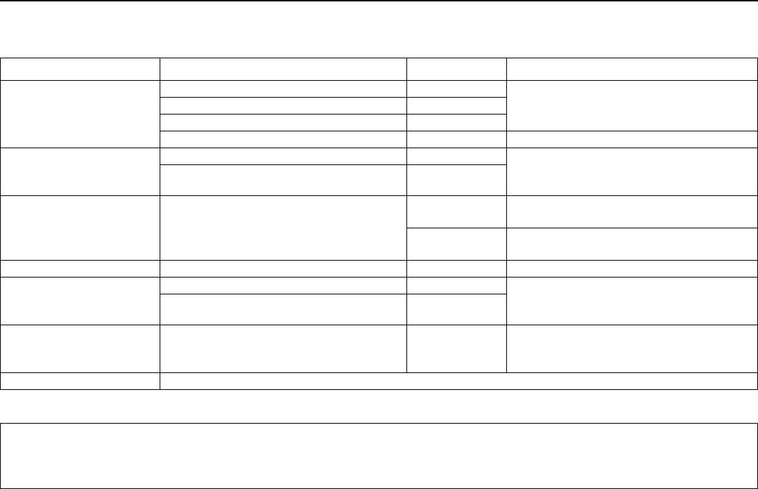
System Triggered
Seatbelt tensioner In a frontal collision and/or side-impact accident and/or overturning.
Airbags (SRS)
In a frontal collision
1
.
Side airbags (SIPS)
In a side-impact accident
1
.
Inflatable Curtain DMIC
In a side-impact accident and/or overturning
1
.
Whiplash protection WHIPS In a rear-end collision.
Roll-Over Protection System (ROPS) In the event of overturning.
1. The bodywork of the car could be greatly deformed in a collision even without airbag deployment. A number of factors such as the rigidity and weight of
the object hit, the speed of the car, the angle of the collision etc. affects how the different safety systems of the car are activated.
WARNING!
The AIRBAG control module is located in
the centre console. If the centre console is
drenched with water or other liquid,
disconnect the battery cables. Do not
attempt to start the car since the airbags
may deploy. Have the car transported to
an authorised Volvo workshop.
WARNING!
Never drive with deployed airbags. They
can make steering difficult. Other safety
systems may also be damaged. The
smoke and dust created when the airbags
are deployed can cause skin and eye
irritation after intensive exposure. In case
of irritation, wash with cold water. The
rapid deployment sequence and airbag
fabric may cause friction and skin burns.
C70 w540.book Page 25 Monday, July 18, 2005 4:25 PM
26
Safety
Crash mode
Driving after a collision
If the car is involved in a collision, the text
CRASH MODE - SEE MANUAL may appear
on the information display. This means that
the car has reduced functionality. CRASH
MODE is a protective state that is enforced
when the collision may have damaged the
car’s vital functions, such as the fuel lines,
sensors for one of the safety systems, or the
brake system.
Attempting to start the car
First, check that no fuel is leaking from the
car. There should be no smell of fuel.
If everything seems normal and you have
checked for indications of fuel leakage, you
may attempt to start the car.
Firstly, remove the ignition key and then
reinsert it. The car’s electronics will then
try to reset themselves to normal mode.
Then try to start the car. If CRASH MODE
is still shown on the display then the car
must not be driven or towed. Even if the
car appears to be driveable, hidden
damage may make the car impossible to
control once moving.
Moving the car
If NORMAL MODE is shown after CRASH
MODE has been reset, the car can be moved
carefully out of a dangerous position. Do not
move the car further than necessary.
WARNING!
Never attempt to repair your car or reset
the electronics yourself if the car has been
in CRASH MODE. This could result in
personal injury or the car not functioning
as normal. Always allow an authorised
Volvo workshop to check and restore the
car to normal status after CRASH MODE
has been displayed.
WARNING!
Never, under any circumstances, attempt
to restart the car if it smells of fuel when
the CRASH MODE message is displayed.
Leave the car at once.
WARNING!
If the car is in CRASH MODE it must not
be towed. It must be transported to an
authorised Volvo workshop.
C70 w540.book Page 26 Monday, July 18, 2005 4:25 PM
27
Safety
Inspecting the airbags and inflatable curtains
Inspection intervals
The decal on the door opening shows the
dates (year, month) when you should contact
an authorised Volvo workshop to inspect and,
if necessary, replace the airbags, belt
tensioners and inflatable curtains. If you have
questions concerning the systems, contact
an authorised Volvo workshop.
1. Driver airbag
2. Front passenger airbag
3. Side airbag on the driver’s side
4. Side airbag on the passenger side
5. Inflatable curtain on the driver’s side
6. Inflatable curtain on the passenger side
This decal is located in the right-hand door
opening.
C70 w540.book Page 27 Monday, July 18, 2005 4:25 PM
28
Safety
Child safety
Children should sit comfortably
and safely
The position of a child in the car and the
choice of equipment is dictated by the child’s
weight and size. For more information see
page 30.
Children who are shorter than 150 cm must
be carried in adequate child protection.
NOTE! Regulations regarding the placement
of children in cars vary from country to
country. Check what laws apply.
Children of all ages and sizes must always sit
correctly secured in the car. Never allow a
child to sit on the knee of a passenger.
Volvo’s own child safety equipment is
designed for your car. Use Volvo genuine
equipment to best ensure that the mounting
points and attachments are correctly
positioned and are sufficiently strong.
You may place:
a child seat or booster cushion on the
front passenger seat, provided the
passenger airbag is not activated
1
.
a rear-facing child seat in the rear seat
that uses the back of the front seat as
support.
Child seats and airbags are not compatible.
Child seats and airbags
Always place a child in the rear seat if the
passenger airbag is activated
1
. A child in a
child seat on the front passenger seat may
suffer serious injury if the airbag deploys.
1. For information on activated/deacti-
vated airbag (SRS) see page 17.
WARNING!
Persons shorter than 140 cm may only sit
in the front passenger seat if the
passenger airbag is deactivated
1
.
C70 w540.book Page 28 Monday, July 18, 2005 4:25 PM
29
Safety
Child safety
Location of airbag decal in door opening on
front passenger side.
Decal located on instrument panel end face. Decal located on instrument panel end face.
(Australia only).
WARNING!
Never place a child in a child seat or on a
booster cushion in the front seat if the
airbag (SRS) is activated
1
. Failure to
follow this advice can endanger the life of
the child.
1. For information on activated/deacti-
vated airbag (SRS) see page 17.
C70 w540.book Page 29 Monday, July 18, 2005 4:25 PM
30
Safety
Child safety
Placement of children in the car
Weight/age
Front seat
1
Outer rear seat
<10 kg
(0–9 months)
Rear-facing child seat, secured with
seatbelt and straps. Use a
protective cushion between the
child seat and the dashboard.
L
2
: Type approval no. E5 03135
Rear-facing child seat, secured with
seatbelt, support legs and straps.
L
2
: Type approval no. E5 03135
9–18 kg
(9–36 months)
Rear-facing child seat, secured with
seatbelt and straps. Use a
protective cushion between the
child seat and the dashboard.
L
2
: Type approval no. E5 03135
Rear-facing child seat, secured with
seatbelt, support legs and straps.
L
2
: Type approval no. E5 03135
15–36 kg
(3–12 years)
Booster cushion with or without
backrest.
L
2
: Type approval no. E5 03139
Alternative: Booster cushion with or
without backrest.
L
2
: Type approval no. E5 03139
1. For information on activated/deactivated airbag (SRS) see page 17.
2. L: Suitable for certain child seats as listed in the specified type approval. Child seats can be vehicle-specific,
limited, semi-universal or universal.
C70 w540.book Page 30 Monday, July 18, 2005 4:25 PM
31
Safety
Child safety
ISOFIX fixture system for child
seats
The rear seat has attachment points for the
ISOFIX fixture system for child seats. Contact
an authorised Volvo workshop for further
information on child safety equipment.
Fitting a child seat
Volvo has child safety products that are
designed for and tested by Volvo.
When using other products that are available
on the market, it is important to read the fitting
instructions included with the product.
Do not attach the straps for the child seat
to the horizontal adjustment bar, springs,
rails or beams under the seat. Sharp
edges can damage the straps.
Allow the back of the child seat to rest
against the dashboard. This applies to
cars without a passenger airbag, or
where the airbag is deactivated.
WARNING!
Never place a child in a child seat or on a
booster cushion in the front seat if the
airbag (SRS) is activated
1
.
No one shorter than 140 cm should sit in
the front passenger seat if the airbag
(SRS) is activated.
1
Failure to follow the advice given above
can endanger the life of the child.
1. For information on activated/deacti-
vated airbag (SRS) see page 17.
WARNING!
Never place the child seat in the front seat
if the car is equipped with an activated
1
front passenger airbag. If problems arise
when fitting child safety products, contact
the manufacturer for clearer instructions.
C70 w540.book Page 31 Monday, July 18, 2005 4:25 PM
32
Safety
C70 w540.book Page 32 Monday, July 18, 2005 4:25 PM
33
Instruments and controls
Overview, left-hand drive car 34
Overview, right-hand drive car 36
Driver’s door control panel 38
Combined instrument panel 39
Indicator and warning symbols 40
Information display 44
Electrical socket 45
Lighting panel 46
Left-hand stalk switch 47
Right-hand stalk switch 49
Cruise control (option) 51
Steering wheel keypad (option) 52
Steering wheel adjustment, hazard warning flashers 53
Power windows 54
Rearview and door mirrors 55
Personal preferences 58
C70 w540.book Page 33 Monday, July 18, 2005 4:25 PM
34
Instruments and controls
Overview, left-hand drive car
Left-hand drive.
C70 w540.book Page 34 Monday, July 18, 2005 4:25 PM
35
Instruments and controls
Overview, left-hand drive car
1. Steering wheel adjustment ..................................................page 53
2. Opening handle, bonnet....................................................page 158
3. Control panel, windows and door mirrors.......page 38/page 56
4. Stalk switch, left.....................................................................page 47
5. Lighting panel and fuel filler flap opener...........................page 46
6. Door handle and lock button...............................................page 96
7. Indicator lamp, locking..........................................................page 96
8. Air vents, dashboard .............................................................page 62
9. Air vent for side window
10. Keypad, steering wheel, left ................................................page 51
11. Horn and airbags ...................................................................page 14
12. Combined instrument panel ................................................page 39
13. Keypad, steering wheel, right..............................................page 52
14. Stalk switch, right...................................................................page 49
15. Ignition................................................................................... page 106
16. Rearview mirror, interior........................................................page 55
17. Seatbelt reminder ..................................................................page 11
18. Switch, passenger compartment lighting,
left-hand side ..........................................................................page 79
19. Switch, alarm detectors and deadlocks............................page 98
20. Switch, passenger compartment
automatic lighting...................................................................page 80
21. Switch, optional equipment .................................................page 98
22. Switch, passenger compartment lighting,
right-hand side........................................................................page 79
23. Display, car settings/sound system etc. .......page 58/page 182
24. Controls, car settings/sound system etc......page 58/page 182
25. Climate control .......................................................................page 64
26. Indicator lamp, hazard warning flashers ...........................page 53
27. Door handle and lock button...............................................page 96
28. Glovebox..................................................................................page 82
29. Gear lever, manual/automatic .......................page 108/page 110
30. Parking brake....................................................................... page 114
31. Electrical socket and cigarette lighter...............................page 45
32. Switch, roof control...............................................................page 75
C70 w540.book Page 35 Monday, July 18, 2005 4:25 PM
36
Instruments and controls
Overview, right-hand drive car
Right-hand drive.
C70 w540.book Page 36 Monday, July 18, 2005 4:25 PM
37
Instruments and controls
Overview, right-hand drive car
1. Switch, roof control ...............................................................page 75
2. Electrical socket and cigarette lighter...............................page 45
3. Parking brake....................................................................... page 114
4. Control panel, windows and door mirrors.......page 38/page 56
5. Glovebox..................................................................................page 82
6. Door handle and lock button...............................................page 96
7. Indicator lamp, locking..........................................................page 96
8. Air vent for side window
9. Air vents, dashboard .............................................................page 62
10. Climate control .......................................................................page 64
11. Controls, car settings/sound system etc......page 58/page 182
12. Display, car settings/sound system etc. .......page 58/page 182
13. Switch, passenger compartment lighting,
left-hand side ..........................................................................page 79
14. Switch, alarm detectors and deadlocks............................page 98
15. Switch, passenger compartment automatic lighting......page 80
16. Switch, optional equipment .................................................page 98
17. Switch, passenger compartment lighting,
right-hand side........................................................................page 79
18. Seatbelt reminder ..................................................................page 11
19. Rearview mirror, interior........................................................page 55
20. Ignition................................................................................... page 106
21. Stalk switch, left.....................................................................page 47
22. Keypad, steering wheel, left ................................................page 51
23. Combined instrument panel ................................................page 39
24. Horn and airbags ...................................................................page 14
25. Keypad, steering wheel, right..............................................page 52
26. Indicator lamp, hazard warning flashers ...........................page 53
27. Door handle and lock button...............................................page 96
28. Lighting panel and fuel filler flap opener ..........................page 46
29. Stalk switch, right ..................................................................page 49
30. Opening handle, bonnet ................................................... page 158
31. Lever, steering wheel adjustment ......................................page 53
32. Gear lever, manual/automatic
transmission......................................................page 108/page 110
C70 w540.book Page 37 Monday, July 18, 2005 4:25 PM
38
Instruments and controls
Driver’s door control panel
1. Power windows, all windows down/up
2. Power windows
3. Door mirror, left-hand side
4. Door mirrors, setting
5. Door mirror, right-hand side.
C70 w540.book Page 38 Monday, July 18, 2005 4:25 PM
39
Instruments and controls
Combined instrument panel
1. Speedometer
2. Direction indicators, left
3. Warning symbol
4. Information display
The display presents information or warning
messages, outside temperature and the time.
When the outside temperature is between
+2 °C and –5 °C, a snowflake symbol
appears on the display. This warns of icy
roads. The outside temperature gauge may
show a slightly high reading after the car has
been stationary.
5. Information symbol
6. Direction indicator, right
7. Tachometer
Indicates engine speed in thousands of
revolutions per minute (rpm).
8. Indicator and warning symbols
9. Fuel gauge
10. Button for trip meter
Used to measure short distances. Press the
button to switch between trip meters T1 and
T2. Press and hold (more than 2 seconds) to
zero the active trip meter.
11. Display
Display for automatic gear position, rain
sensor, odometer, trip meter and cruise
control.
12. Main beam indicator
13. Knob for clock
Turn the knob to adjust the time.
14. Temperature gauge
Displays the temperature of the engine
cooling system. A message will appear on the
display if the temperature becomes too high
and the gauge goes into the red zone. Bear in
mind that extra lights placed in front of the air
intake, for example, reduce the cooling
capacity at high outside temperatures and
high engine loads.
15. Indicator and warning symbols
C70 w540.book Page 39 Monday, July 18, 2005 4:25 PM
40
Instruments and controls
Indicator and warning symbols
Functionality check, symbols
All indicator and warning symbols illuminate
when the ignition key is turned to position II
before starting. This is to check that the
symbols are working. When the engine
starts, all the symbols should go out except
the handbrake symbol, which extinguishes
when the handbrake is released.
If the engine does not start
within five seconds, all symbols
extinguish except the symbols
for a fault in the car’s emissions
system and for low oil
pressure. Certain symbols may
not function, depending on the car’s specifi-
cations.
Symbols in the centre of the
instrument panel
The red warning symbol illumi-
nates when a fault has been
indicated which could affect the
safety and/or driveability of the
car. An explanatory text is shown on the infor-
mation display at the same time. The symbol
and message text remain visible until the fault
has been rectified. The warning symbol can
also illuminate in conjunction with other
symbols.
Stop in a safe place. Do not drive the car
further.
Read the information on the information
display.
Rectify the fault as instructed or contact
an authorised Volvo workshop.
When one of the car’s systems
does not behave as intended,
the yellow information symbol
illuminates and a text appears on
the information display. The
message text is cleared using the READ
button, see page 44, or disappears automat-
ically after 2 minutes.
The yellow information symbol can also come
on in conjunction with other symbols.
NOTE! When the message text "TIME FOR
REGULAR SERVICE" is shown, the symbol
lamp and message text are cleared using the
READ button, or disappear automatically
after 2 minutes.
C70 w540.book Page 40 Monday, July 18, 2005 4:25 PM
41
Instruments and controls
Indicator and warning symbols
Indicator symbols – left-hand
side
1. Fault in car’s emissions system
Drive to an authorised Volvo
workshop to have the system
checked.
2. ABS fault
If this symbol lights, the system is
not working. The car’s regular
brake system continues to work,
but without the ABS function.
Stop the car in a safe place and turn off
the engine.
Restart the engine.
Drive to an authorised Volvo workshop to
have the ABS checked if the symbol
remains lit.
3. Rear fog lamp
This symbol is lit when the rear
fog lamp is on.
4. Stability system DSTC
A flashing symbol indicates that
the stability system is operating.
5. No function
6. No function
7. Low level in fuel tank
This symbol lights when there are
approximately 8 litres of fuel left.
Indicator symbols – right-hand
side
1. Indicator symbol for trailer
This symbol flashes when the
direction indicators are used and
a trailer is coupled. If the symbol
does not flash, one of the lamps
on the trailer or the car is defective.
2. Parking brake applied
The lamp comes on when the
parking brake is applied. Always
pull the parking brake lever to the
end position.
NOTE! The lamp comes on irrespective of
how hard the parking brake is applied.
C70 w540.book Page 41 Monday, July 18, 2005 4:25 PM
42
Instruments and controls
Indicator and warning symbols
3. Airbags – SRS
If this symbol remains on or
comes on while driving, it means
a fault has been detected in the
seatbelt buckle, SRS, SIPS,
ROPS or DMIC system. Drive directly to an
authorised Volvo workshop to have the
system checked.
4. Low oil pressure
If this symbol lights up while
driving, the engine oil pressure is
too low. Stop the engine immedi-
ately and check the engine oil
level, top up if necessary. If the symbol lights
up and the oil level is normal, contact an
authorised Volvo workshop.
5. Seatbelt reminder
This symbol lights if someone in a
front seat has not put on their
seatbelt or if someone in a rear
seat has taken off their seatbelt.
6. Alternator not charging
If this symbol lights while driving,
a fault has occurred in the
electrical system. Contact an
authorised Volvo workshop.
7. Fault in brake system
If this symbol lights, the brake
fluid level may be too low.
Stop the car in a safe place and check the
level in the brake fluid reservoir, see
page 162. If the level in the reservoir is
below MIN, the car should not be driven
any further. Have the car transported to
an authorised Volvo workshop to have the
brake system checked.
If the BRAKE and ABS symbols
come on at the same time, there
may be a fault in the brake force
distribution system.
Stop the car in a safe place and
turn off the engine.
Restart the engine.
If both symbols extinguish, continue
driving.
If the symbols remain on, check the level
in the brake fluid reservoir. See page 162.
If the brake fluid level is normal but the
symbols are still lit, the car can be driven,
with great care, to an authorised Volvo
workshop to have the brake system
checked.
If the level in the reservoir is below MIN,
the car should not be driven any further.
Have the car transported to an authorised
Volvo workshop to have the brake system
checked.
WARNING!
If the BRAKE and ABS symbols are illumi-
nated at the same time, there is a risk that
the rear end will skid during heavy braking.
C70 w540.book Page 42 Monday, July 18, 2005 4:25 PM
43
Instruments and controls
Indicator and warning symbols
Reminder – doors not closed
If one of the doors, the bonnet
1
or the boot lid
is not properly closed, the driver will be
reminded of this.
Low speed
If the car is travelling at a speed
lower than approx. 7 km/h, the
information symbol will light and
one of the following texts will be
shown on the display: DRIVER
DOOR OPEN, PASSENGER DOOR OPEN,
or ENGINE HOOD OPEN. Stop the car as
soon as it is safe to do so and close the open
door or bonnet.
High speed
If the car is moving faster than
approx. 7 km/h, the symbol
illuminates and one of the texts
indicated in the previous
paragraph appears on the display.
Boot lid reminder
If the boot lid is open, this infor-
mation symbol will come on and
TAILGATE OPEN will appear
on the display.
1. Only cars with alarm.
C70 w540.book Page 43 Monday, July 18, 2005 4:25 PM
44
Instruments and controls
Information display
Messages
When a warning or indicator symbol comes
on, a message appears on the information
display.
Press the READ button (A).
Switch between messages with the READ
button. Fault messages are stored in the
memory until the fault is rectified.
NOTE! If a warning message appears while
you are using the trip computer, the message
must be read (press READ) before the
previous activity can be resumed.
Message Action
STOP SAFELY Stop and switch off the engine. Serious risk of damage.
STOP ENGINE Stop and switch off the engine. Serious risk of damage.
SERVICE URGENT Have the car checked by a workshop immediately. An authorised Volvo workshop is recom-
mended.
SEE MANUAL Read the owner’s manual.
SERVICE REQUIRED Have the car checked by an authorised Volvo workshop as soon as possible. An authorised
Volvo workshop is recommended.
TIME FOR REGULAR SERVICE Time for regular service. An authorised Volvo workshop is recommended. The timing is
determined by the number of kilometres driven, number of months since the last service and
engine running time.
CHECK OIL LEVEL The message is a reminder that the oil level must be checked and is shown every
10 000 km. For information on checking the oil level, see page 160.
C70 w540.book Page 44 Monday, July 18, 2005 4:25 PM
45
Instruments and controls
Electrical socket
The electrical socket can be used for 12 V
accessories, such as mobile phone chargers
and coolers. The maximum current is 10 A.
For the socket to supply current, the ignition
key must be in at least position I.
Cigarette lighter (option)
Activate the lighter by pushing in the button.
The button pops out when the lighter is hot.
Pull out the lighter and light a cigarette on the
heated coils.
WARNING!
Always leave the plug in the socket when
the socket is not in use.
C70 w540.book Page 45 Monday, July 18, 2005 4:25 PM
46
Instruments and controls
Lighting panel
Headlamp levelling
The load in the car changes the vertical
alignment of the headlamp beam, which
could dazzle oncoming motorists. Avoid this
by adjusting the height of the beam.
Turn the ignition key to position II.
Turn the headlamp control (2) to one of
the end positions.
Roll the control up or down (1) to raise or
lower beam alignment.
Cars with Bi-Xenon headlamps
1
have
automatic headlamp levelling, so there is no
control (1).
Position/parking lamps
The position lamps/parking lamps can be
switched on irrespective of ignition key
position.
Turn the headlamp control (2) to the
centre position.
In ignition key position II the position lamps/
parking lamps are always on. The number
plate lighting is switched on at the same time
as the position lamps/parking lamps.
Headlamps
Automatic dipped beam (certain
countries)
Dipped beam comes on automatically when
the ignition key is turned to position II, except
when the headlamp control (2) is in the
centre position. If necessary, the automatic
dipped beam can be deactivated by an
authorised Volvo workshop.
Manual dipped beam
Turn the ignition key to position II.
Turn the headlamp control (2) clockwise
to the end position.
Main beam
Turn the ignition key to position II.
Turn the headlamp control (2) clockwise
to the end position.
Move the left-hand stalk switch towards
the steering wheel to the end position
and release it, see page 47.
Fuel filler flap
Button (5) opens the fuel filler flap.
Fog lamp
NOTE! Regulations for use of fog lamps vary
from country to country.
Front fog lamps (option)
The front fog lamps can be switched on along
with the headlamps or the position lamps/
parking lamps.
Press the button (4).
The LED in the button (4) lights when the
front fog lamps are switched on.
Rear fog lamp
The rear fog lamp can only be switched on
with the headlamps or the front fog lamps.
Press the button (6).
The rear fog lamp indicator symbol on the
combined instrument panel and the LED in
the button (6) come on when the rear fog
lamp is switched on.
Instrument lighting
The instrument lighting is switched on when
the ignition key is in position II and the
headlamp control (2) is in one of the end
positions. The lighting is automatically
dimmed during the day and can be controlled
manually at night.
Roll the control up or down (3) for
brighter or dimmer lighting.
1. Option.
C70 w540.book Page 46 Monday, July 18, 2005 4:25 PM
47
Instruments and controls
Left-hand stalk switch
Stalk switch positions
1. Short flash sequence, direction
indicators.
2. Continuous flash, direction indicators.
3. Main beam flash.
4. Switching, main and dipped beam, and
home safe lighting.
Direction indicators
Continuous flash sequence
Move the stalk switch up or down to end
position (2).
The stalk switch remains in its end position
and is moved back manually, or automatically
by steering wheel movement.
Short flash sequence
Move the stalk switch up or down to
position (1) and release.
The direction indicators flash three times and
the stalk switch returns to its home position.
Switching, main and dipped
beam
The ignition key must be in position II for main
beam to be switched on.
Turn the headlamp control clockwise to
the end position, see page 46.
Move the stalk switch towards the
steering wheel to the end position (4) and
release.
Main beam flash
Move the stalk switch gently towards the
steering wheel to position (3).
Main beam comes on until the stalk switch is
released.
Home safe lighting
Some exterior lights can be kept lit and serve
as home safe lighting after the car is locked.
The standard delay is 30 seconds
1
, but can
be changed to 60 or 90 seconds; see
page 59.
Remove the key from the ignition switch.
Move the stalk switch towards the
steering wheel to the end position (4) and
release.
Get out of the car and lock the door.
1. Factory settings.
C70 w540.book Page 47 Monday, July 18, 2005 4:25 PM
48
Instruments and controls
Left-hand stalk switch
Trip computer
To scroll through trip computer functions and
other menus, turn the thumbwheel (B) either
up or down in steps. Continue turning to
return to the starting point.
NOTE! If a warning message interrupts while
you are using the trip computer, this message
must be acknowledged. Acknowledge by
pressing the READ button (A) and revert to
the trip computer function.
Functions
•AVERAGE SPEED
CURRENT CONSUMPTION
•AVERAGE CONSUMPTION
•RANGE TO EMPTY FUEL TANK
SPEED IN MILES PER HOUR
1
DSTC see page 115
PARKING HEATER (option, parking
heater see page 68)
Average speed
When the ignition is switched off, the
average speed is stored and used as the
basis of the new value when you continue
driving. Reset using the RESET button (C).
Current fuel consumption
Current fuel consumption is calculated every
second. The information on the display is
updated every couple of seconds. When the
car is stationary, "----" appears on the display.
Average fuel consumption
The average fuel consumption since the last
reset (RESET). The average fuel
consumption is stored when the ignition is
switched off and remains until the function is
reset. Reset using the RESET button (C).
NOTE! There may be a slight error in the
reading if a fuel-driven heater is used.
Range to empty fuel tank
The range to empty is calculated based on
the average fuel consumption over the last
30 km. When the range to empty is shorter
than 20 km then "----" is shown on the
display.
Speed in miles per hour
1
Current speed is displayed in mph.
NOTE! There may be a slight error in the
reading if fuel consumption is changed due to
a change in driving style or if a fuel-driven
heater is used for example.
Resetting
Select AVERAGE SPEED or AVERAGE
CONSUMPTION.
Press and hold the RESET button (C) for
at least five seconds to reset the average
speed and average fuel consumption at
the same time.
1. Certain countries.
C70 w540.book Page 48 Monday, July 18, 2005 4:25 PM
49
Instruments and controls
Right-hand stalk switch
Windscreen wipers
A. Windscreen and headlamp washers
B. Rain sensor – On/Off
C. Thumbwheel
D. No function
Windscreen wipers off
The windscreen wipers are off
when the stalk switch is in
position 0.
Single sweep
Raise the stalk switch to make a
single sweep.
Intermittent wiping
The delay between sweeps can
be adjusted. Turn the
thumbwheel (C) clockwise for a
shorter interval between
sweeps. Turn it anticlockwise to
increase the delay.
Continuous wiping
The wipers sweep at normal
speed.
The wipers sweep at high
speed.
Windscreen/headlamp washer
Pull the stalk switch towards the steering
wheel to start the windscreen and headlamp
washers. The wipers will make three more
sweeps once the stalk is released.
High-pressure headlamp washing
(option in certain markets)
High-pressure headlamp washing consumes
a large quantity of washer fluid. To save fluid,
the headlamps are washed as follows.
Dipped beam selected with the switch on
lighting panel:
The headlamps are washed the first time the
windscreen is washed. Within the next ten
minutes, they are washed every fifth wash of
the windscreen. If more than ten minutes
passes between washes, the headlamps are
washed every time.
Parking/position lamps selected with the
switch on the lighting panel:
Bi-Xenon headlamps are only washed
every fifth wash cycle irrespective of the
time that elapses.
Halogen headlamps are not washed.
The switch on the lighting panel is in
position 0:
Bi-Xenon headlamps are only washed
every fifth wash cycle irrespective of the
time that elapses.
Halogen headlamps are not washed.
IMPORTANT!
Use plenty of washer fluid when the
wipers are cleaning the windscreen. The
windscreen must be wet when the
windscreen wipers are operating.
C70 03 Instruments and controls w540.fm Page 49 Wednesday, August 3, 2005 2:18 PM
50
Instruments and controls
Right-hand stalk switch
Rain sensor (option)
The rain sensor automatically activates the
windscreen wipers based on how much
water it detects on the windscreen. The
sensitivity of the rain sensor can be adjusted
using the thumbwheel (C).
Turn the thumbwheel clockwise to increase
sensitivity or anticlockwise to decrease sensi-
tivity, (there is an extra swipe when the
thumbwheel is turned clockwise.)
On/Off
When activating the rain sensor, the ignition
key must be in position I or II and the
windscreen wiper stalk switch must be in
position 0.
To activate the rain sensor:
press the button (B). An LED in the
button comes on to indicate that the rain
sensor is active.
To turn the rain sensor off, either:
press button (B).
press the stalk switch downward to
another wiper program. If the stalk switch
is raised, the rain sensor will remain
active; the wipers make an extra sweep
and then return to rain sensor mode when
the stalk is released to position 0.
The rain sensor is automatically deactivated
when the key is removed from the ignition
switch or five minutes after the ignition is
switched off.
Thumbwheel
Use the thumbwheel to adjust the frequency
of sweeps when intermittent wiping is
selected, or the sensitivity to rain when the
rain sensor is selected.
IMPORTANT!
At an automatic car wash:
Deactivate the rain sensor by pressing
the button (B) while the ignition key is in
position I or II. Otherwise, the
windscreen wipers could start swiping
and become damaged.
C70 03 Instruments and controls w540.fm Page 50 Friday, October 21, 2005 9:49 AM
51
Instruments and controls
Cruise control (option)
Activating
The controls for cruise control are to the left
of the steering wheel.
Setting the desired speed:
Press the CRUISE button. CRUISE is
shown on the combined instrument panel.
–Touch + or to lock the vehicle speed.
CRUISE-ON appears on the combined
instrument panel.
Cruise control cannot be engaged at speeds
below 30 km/h or above 200 km/h.
Increasing or decreasing speed
Increase or decrease the locked speed by
pressing and holding + or . The speed of
the car when the button is released is set
as the new speed.
Pressing (less than half a second) + or
changes the speed 1 km/h or 1.6 km/h
1
.
NOTE! A temporary increase in speed (less
than one minute) using the accelerator, such
as while overtaking, does not affect the cruise
control setting. When you release the accel-
erator, the car will return to the programmed
speed.
Temporary disengagement
–Press0 to disengage the cruise control
temporarily. CRUISE will be shown on the
combined instrument panel. The speed
set earlier is stored in the memory.
The cruise control is also temporarily disen-
gaged when:
the brake pedal or clutch pedal is
depressed
speed falls below 25–30 km/h when
travelling uphill
1
the gear selector is moved to position N
wheel spin or wheel lock-up occurs
a temporary increase in speed lasts
longer than one minute.
Return to the set speed
Press this button to resume the
previously set speed.
CRUISE-ON appears on the
combined instrument panel.
Disengaging
Press CRUISE to disengage the cruise
control. CRUISE-ON goes out on the
combined instrument panel.
1. Depending on engine type.
C70 w540.book Page 51 Monday, July 18, 2005 4:25 PM
52
Instruments and controls
Steering wheel keypad (option)
Button functions
The four buttons at the bottom of the steering
wheel keypad control the radio and the
telephone. The function of a button depends
on which system is active. The steering wheel
keypad can be used to scroll between preset
stations, change CD/MD tracks and adjust
the volume.
Press and hold one of the arrow keys to fast
forward/reverse or search for the next station.
The telephone must be in standby mode to
adjust audio system settings.
The telephone must be activated to control
the telephone functions using the arrow keys.
For more information on telephone functions,
see page 192.
C70 w540.book Page 52 Monday, July 18, 2005 4:25 PM
53
Instruments and controls
Steering wheel adjustment, hazard warning flashers
Steering wheel adjustment
The steering wheel can be adjusted for both
height and reach.
Pull the lever towards you to release the
steering wheel.
Adjust the steering wheel to the position
that suits you best.
Push back the lever to fix the steering
wheel in place. If the lever is stiff, press
the steering wheel lightly at the same time
as you push the lever back.
Hazard warning flashers
Use the hazard warning flashers (all direction
indicators flash) when the car is stopped
where it could be a traffic hazard or
obstruction. Press the button to activate the
function.
NOTE! Regulations regarding the use of
hazard warning flashers vary from country to
country.
WARNING!
Adjust the steering wheel before driving
off, never while driving. Before driving,
check that the steering wheel is fixed in
position.
C70 w540.book Page 53 Monday, July 18, 2005 4:25 PM
54
Instruments and controls
Power windows
General
Closing of front windows is stopped if
anything prevents their movement.
Manual operation means that the window
stops moving when its control has been
released. During automatic operation the
movement of the window continues after its
control has been released.
Operation from outside
Operation from outside is possible when the
doors are closed and the ignition key is
removed from the ignition switch.
Front windows simultaneously –
opening only
Press the remote control unlocking button
(see page 90) to open the front windows.
The windows are opened automatically. A
short press on the unlocking button stops the
opening.
Control panel, driver’s door.
Operation from inside
All windows can be operated from the
driver’s door control panel. Only the
passenger door window can be operated
from the passenger door control panel.
The windows can still be operated after the
engine has been switched off as long as the
doors are kept closed. Otherwise the ignition
key must first be turned to position I or II.
One window at a time
Manual operation takes place by means of
the control (A or B) being moved up/down
halfway. Automatic operation takes place by
means of the control being moved up/down
fully. Only the front windows can be closed
automatically.
The control on the passenger door is
operated in the same way as on the driver’s
door.
All windows simultaneously
All windows can be opened and closed
simultaneously using button (C). The
windows are opened automatically with a
short press on the right-hand side of the
button. Close by keeping the left-hand side of
the button pressed in.
WARNING!
Check that objects or people, especially
children, do not get trapped when the
windows are closed. Remove the ignition
key if anyone is left in the car.
C70 w540.book Page 54 Monday, July 18, 2005 4:25 PM
55
Instruments and controls
Rearview and door mirrors
Interior rearview mirror
Dipping
1. Dip the mirror with the lever
2. Normal position
3. Dipped position. Use this to reduce
annoying dazzle from the headlights of
following vehicles.
Autodimming (option)
A sensor (4) on the bottom edge of the mirror
detects light coming from behind and dims
the mirror if the light is strong. An authorised
Volvo workshop can adjust the sensitivity.
NOTE! The illustration is a montage. The
mirror has either manual dipping or automatic
dimming, never both at the same time.
Rearview mirror with compass
(option in certain markets)
The upper right-hand corner of the rearview
mirror has an integrated display that shows
the compass direction in which the front of
the car is pointing. Eight different directions
are shown with English abbreviations: N
(north), NE (north east), E (east), SE (south
east), S (south), SW (south west), W (west)
and NW (north west).
Calibrating the compass
The compass may need calibrating in special
cases (setting points of the compass). The
letter C is shown in the mirror’s display if the
compass needs calibrating.
Stop the car in a large open area.
Start the car.
Press and hold button (1) (use the point
of a pen or similar) for at least six
seconds. The character C will reappear.
Drive slowly in a circle at a speed of no
more than 10 km/h until a compass
direction appears on the display.
Calibration is complete.
C70 w540.book Page 55 Monday, July 18, 2005 4:25 PM
56
Instruments and controls
Rearview and door mirrors
Magnetic zones.
Adjusting the zone
The earth is divided into 15 magnetic zones.
The compass is set for the geographical area
to which the car was delivered.
Select a different compass area as follows:
Turn on the ignition.
Press and hold button (1) for at least
three seconds (use the point of a pen or
similar). The number for the current area
is displayed.
Press the button repeatedly until the
number for the required geographic area
(1–15) is shown.
The display will revert to showing the
compass direction a few seconds after
you stop scrolling.
Door mirrors
The controls for adjusting the two door
mirrors are at the front of the driver’s door
armrest.
–Press theL button for the left-hand door
mirror or R for the right-hand door mirror.
The LED in the button lights.
Adjust the position with the joystick in the
centre.
–Press theL or R button again. The LED
should no longer be lit.
C70 w540.book Page 56 Monday, July 18, 2005 4:25 PM
57
Instruments and controls
Rearview and door mirrors
Retractable power door mirrors
(option)
The mirrors can be retracted for parking and
driving in narrow spaces.
Press down the L and R buttons at the
same time.
Release them after approximately one
second. The mirrors automatically stop in
the fully retracted position.
Folding out the mirrors
Press down the L and R buttons at the
same time. The mirrors automatically stop
in the fully extended position.
Resetting to neutral
Mirrors that have been moved out of position
by an external force must be reset to the
neutral position for electric retracting and
extending to work.
Use the L and R buttons to retract the
mirrors.
Extend the mirrors again with the L and R
buttons. The mirrors are now reset to the
neutral position.
Storing door mirror positions
The positions of the mirrors are stored when
the car is locked with the remote control.
When the car is unlocked with the same
remote control the mirrors and the driver's
seat adopt the stored positions within
five minutes.
Home safe and approach lighting
The lamps on the door mirrors light when the
home safe lighting or approach lighting is
activated.
IMPORTANT!
Do not use a scraper to remove ice from
the mirrors as this can scratch the glass.
Use the defroster function instead, see
page 65.
WARNING!
The driver-side door mirror is wide angled
to provide optimal vision. Objects may
appear further away than they actually are.
C70 w540.book Page 57 Monday, July 18, 2005 4:25 PM
58
Instruments and controls
Personal preferences
Control panel.
Possible settings
Personal preferences can be set for some of
the car’s functions: the locks, climate control
and audio functions. For audio functions, see
page 183.
Control panel
A. Display
B. MENU
C. EXIT
D. ENTER
E. Navigation button
Use
The settings are shown on the display (A).
Open the menu to enter settings:
Press MENU (B).
Scroll, for example, to
Car Settings
with
the navigation button (E).
–Press ENTER(D).
Select an alternative with the navigation
button (E).
Press ENTER (D) to activate the
selection.
Close the menu:
Press EXIT (C) for approximately one
second.
Climate control settings
Automatic fan adjustment
Fan speed in AUTO mode can be adjusted:
Select from
Low,
Normal
and
High
.
Recirculation timer
When the timer is active, the air recirculates
for 3–12 minutes, depending on the outside
air temperature.
Select
On/Off
depending on whether you
wish the recirculation timer to be active.
Reset all
Resets the climate function options to the
factory settings.
Car settings
Unlock feedback light
The hazard warning flashers can provide
feedback when the car is unlocked with the
remote control. This function can be turned
On
or
Off
.
Lock feedback light
The hazard warning flashers can provide
feedback when the car is locked with the
remote control. This function can be turned
On
or
Off
.
Autolock, doors
The doors and boot lid can be locked
automatically when the car starts to move.
The setting options are
On
or
Off
.
Unlock doors
All doors – one press of the remote
control unlocks all doors and the boot lid.
Drivers door first, then all others – one
press of the remote control unlocks the
C70 03 Instruments and controls w540.fm Page 58 Monday, August 1, 2005 9:40 AM
59
Instruments and controls
Personal preferences
driver’s door. A second press then
unlocks the passenger door, and the boot
lid.
Keyless entry
All doors – both front doors and the boot
lid are unlocked simultaneously.
Both front doors – both front doors are
unlocked simultaneously.
One of the front doors – the door closest
to the remote control is unlocked.
Approach lighting
Select the time the car’s lights should remain
on when the approach lighting button is
pressed. The following alternatives are
available: 30/60/90 seconds.
Home safe lighting
Select the time the car’s lights should remain
on when the left-hand stalk switch is pulled
back after the ignition key has been removed.
The following alternatives are available:
30/60/90 seconds.
Information
VIN number (Vehicle Identification
Number). The car’s unique identity
number.
Number of keys. The number of keys
registered for the car is shown.
C70 w540.book Page 59 Monday, July 18, 2005 4:25 PM
60
Instruments and controls
C70 w540.book Page 60 Monday, July 18, 2005 4:25 PM
61
Climate control
General information on climate control 62
Electronic climate control, ECC 64
Air distribution 67
Fuel-driven heater (option) 68
C70 w540.book Page 61 Monday, July 18, 2005 4:25 PM
62
Climate control
General information on climate control
ECC/Air conditioning
The car is equipped with automatic climate
control (ECC). The climate control system
controls the air conditioning (A/C) and the
cooling, heating and dehumidifying of the air
in the passenger compartment.
NOTE! The air conditioning can be switched
off, but to ensure the best possible air in the
passenger compartment and prevent the
windows from misting, it should always be
on.
Misting windows
Reduce the problem of windows misting up
on the inside by cleaning the windows. Use a
regular window cleaner.
Ice and snow
Remove ice and snow from the climate
control air intake (the grille between the
bonnet and the windscreen).
Fault tracing and repair
Entrust fault tracing and repair of the climate
control system to an authorised Volvo
workshop only.
Refrigerant
The climate control system contains R134a
refrigerant. This refrigerant contains no
chlorine, which means that it is harmless to
the ozone layer. The system must only be
charged with R134a refrigerant. Have an
authorised Volvo workshop carry out this
work.
Passenger compartment filter
All air which enters the passenger
compartment is first cleaned by a filter. This
filter must be replaced regularly. Follow the
Volvo Service Programme for the recom-
mended replacement intervals. If the car is
used in a severely contaminated environment,
it may be necessary to replace the filter more
often.
NOTE! There are several different types of
passenger compartment filter. Ensure that
the correct filter is installed.
Display
There is a display above the climate control
panel that displays climate control settings.
Personal preferences
You can set preferences for two climate
control functions:
Fan speed in AUTO mode.
Recirculation timer for passenger
compartment air.
For information about these settings, see
page 58.
Air vents in the dashboard
A. Open
B. Closed
C. Lateral airflow
D. Vertical airflow.
To demist the front side windows:
Aim the outer vents at the side windows.
In cold weather:
Close the centre vents for optimum
comfort and best demisting.
C70 w540.book Page 62 Monday, July 18, 2005 4:25 PM
63
Climate control
General information on climate control
ECC
Actual temperature
The temperature you select corresponds to
the physical experience with reference to
factors such as air speed, humidity and solar
radiation in and around the car.
Sensor location
The sun sensor is on the top side of the
dashboard.
The temperature sensor for the
passenger compartment is behind the
climate control panel.
NOTE! Do not cover or block the sensors
with clothing or other objects.
Side windows
To ensure that the air conditioning works
satisfactorily, close all side windows and the
roof.
Acceleration
The air conditioning switches off temporarily
at full throttle. You may feel a temporary rise
in temperature.
Condensation
In warm weather, condensation from the air
conditioning may drip under the car. This is
normal.
C70 w540.book Page 63 Monday, July 18, 2005 4:25 PM
64
Climate control
Electronic climate control, ECC
Control panel.
1. AUTO
2. Fan
3. Recirculation/Air quality system
4. Defroster
5. Air distribution
6. A/C – ON/OFF
7. Heated front left seat
8. Heated front right seat
9. Rear window and door mirror defrosters
10. Temperature
Functions
1. AUTO
Automatically maintains a
selected passenger
compartment temperature
by regulating heat, fan
speed, recirculation and air
distribution.
When the roof is open more air and heat/cold
is directed down in the passenger
compartment, and the output of the climate
control is limited if it is not possible to
compensate for the outside temperature.
When one or more manual functions are
selected the other functions are controlled
automatically. Pressing AUTO (1) switches
off all manual settings. The display shows
AUTO CLIMATE.
2. Fan
Increase or decrease fan
speed by turning the knob.
The fan speed is regulated
automatically if AUTO (1) is
selected and the previously
set fan speed is disen-
gaged.
NOTE! If the knob is turned anticlockwise
and the fan indication on the display goes
out, the fan and the air conditioning are
switched off. The display shows the fan
symbol and OFF.
C70 04 Climate control w540.fm Page 64 Wednesday, August 3, 2005 2:19 PM
65
Climate control
Electronic climate control, ECC
3. Recirculation
Recirculation can be used to
shut out bad air, exhaust
fumes, etc. from the
passenger compartment.
The air in the passenger
compartment is recirculated,
i.e. no outside air is taken into the car when
this function is activated. If the air in the car
recirculates for too long, there is a risk of
misting on the insides of the windows.
Timer
With the timer function activated (when the
recirculation function is selected) the risk of
ice, mist and bad air is reduced. To activate/
deactivate the function, see page 58.
NOTE! When Defroster (4) is selected, recir-
culation is always deactivated.
3. Air quality system
(same button as recircu-
lation)
The air quality system
consists of a multi-filter and
a sensor. The filter
separates gases and
particles to reduce the levels of odours and
pollution in the passenger compartment.
When the sensor detects polluted outside
air, the air intakes are closed and the air in the
passenger compartment is recirculated. A
green LED (A) lights in the button when the
air quality sensor is active.
Activating the air quality sensor:
Press the AUTO (1) button to activate the
air quality sensor (normal setting).
Or:
Switch between three functions by
pressing the recirculation button
repeatedly:
Keep in mind the following:
As a rule, the air quality sensor should
always be engaged.
Recirculation is limited in cold weather to
avoid misting.
If the insides of the windows start misting
up, disengage the air quality sensor.
The defroster function for the front, side
and rear windows can also be used to
demist the windows.
4. Defroster
Defroster quickly removes
misting and ice from the
windscreen and side
windows. Air flows to the
windows at high fan speed.
The LED in the defroster
button lights when the function is active. The
air conditioning gives maximum dehumidifi-
cation. The air is not recirculated.
5. Air distribution
The airflow can be
distributed to the windows,
dashboard vents or floor by
pressing the air distribution
buttons.
A symbol on the display
above the climate control panel and a lit LED
in the button indicate which function has
been selected.
See the table on page 67.
6. A/C – ON/OFF
The air conditioning is
controlled automatically by
the system when the ON
LED is lit. This way,
incoming air is sufficiently
cooled and dehumidified.
When the OFF LED is lit, the air conditioning
is always disengaged. Other functions are
Air quality sensor
engaged.
LED (A)
comes on.
Recirculation engaged,
providing cooling in a
warm climate is not
required.
No LED
comes on.
Recirculation engaged. LED (M)
comes on.
C70 w540.book Page 65 Monday, July 18, 2005 4:25 PM
66
Climate control
Electronic climate control, ECC
still controlled automatically. When
defroster (4) is selected, the air conditioning
system is set for maximum dehumidification.
7. and 8. Heated front seats
(option in certain markets)
To activate front seat
heating:
9. Rear window and door mirror
defrosters
Heating is used to quickly
remove misting and ice from
the rear window and door
mirrors.
The rear window and door
mirrors are defrosted simul-
taneously if the switch is pressed once. The
function is active if one LED is lit in the switch.
The door mirror heating is deactivated
automatically after approximately six minutes.
The rear window heating is deactivated
automatically after approximately twelve
minutes.
NOTE! This function is automatically deacti-
vated when the roof is open.
10. Temperature selector
The temperatures on the
driver and passenger sides
can be set independently.
Press the button once to
activate one side. Press
again to activate the other
side. Press the button a third time to activate
both sides.
The active side is indicated by an LED in the
button and on the display above the climate
control panel.
When the car is started, the most recent
setting is resumed.
NOTE! Heating or cooling cannot be
hastened by selecting a higher or lower
temperature than the actual desired temper-
ature.
Higher heat level:
— Press the button once.
Both LEDs
come on.
Lower heat level:
— Press the button twice.
One LED
comes on.
Heat off:
— Press the button three
times.
No LED
comes on.
C70 w540.book Page 66 Monday, July 18, 2005 4:25 PM
67
Climate control
Air distribution
Air distribution Use: Air distribution Use:
Air to windows. Some
air flows to the
dashboard air vents.
The air is not recircu-
lated. Air conditioning is
always engaged.
To remove ice and
misting quickly.
Air to the floor and
windows. Some air
flows to the dashboard
air vents.
To ensure
comfortable condi-
tions and good
demisting in cold or
humid weather.
Air to windscreen and
side windows. Some air
flows to the dashboard
air vents.
To prevent misting
and icing in a cold
and humid climate.
(Not for low fan
speed.)
Air to floor and from
dashboard air vents.
In sunny weather
with cool outside
temperatures.
Airflow to windows and
from dashboard air
vents.
To ensure good
comfort in warm, dry
weather.
Air to the floor. Some
air flows to the
dashboard air vents
and windows.
To warm/cool the
feet.
Airflow to the head and
chest from the
dashboard air vents.
To ensure efficient
cooling in warm
weather.
Airflow to windows,
from dashboard air
vents and to the floor.
To warm/cool the
feet or provide
warmer air to the
upper body in cold
weather or hot, dry
weather.
C70 w540.book Page 67 Monday, July 18, 2005 4:25 PM
68
Climate control
Fuel-driven heater (option)
General information about
heaters
The parking heater can be started immedi-
ately or set with two different start times
using TIMER 1 and TIMER 2. Here, start time
refers to the time the car is heated and ready.
The car’s electronic system calculates when
heating should be started based on the
outside temperature. The heater is not run if
the outdoor temperature exceeds 25 °C. At
temperatures of –10 °C and below, the
maximum running time of the parking heater
is 60 minutes.
Warning decal on fuel filler flap
.
WARNING!
The car must be outdoors when the
parking heater is used.
WARNING!
Switch off the fuel-driven heater before
refuelling. Spilled fuel could be ignited by
the exhaust gases.
Check the information display to see that
the heater is off. (When the parking heater
is running, PARK HEAT ON is shown on
the information display.)
C70 w540.book Page 68 Monday, July 18, 2005 4:25 PM
69
Climate control
Fuel-driven heater (option)
Activating the heater
Enter the time when the car is to be used.
Press RESET (C) to enter the hours and
minutes.
Press and hold the RESET button until
the timer is activated.
Parking on a hill
If the car is parked on a steep hill, the front of
the car should point downhill to ensure that
there is a supply of fuel to the parking heater.
Direct start
Use the thumbwheel (B) to scroll to
DIRECT START.
Press RESET (C) to access the options
ON and OFF.
Select ON.
The heater will now run for 60 minutes.
Heating of the passenger compartment will
begin as soon as the engine coolant has
reached a temperature of 30 ºC.
Immediate stop of heater
Use the thumbwheel (B) to scroll to
DIRECT START.
Press RESET (C) to access the options
ON and OFF.
Select OFF.
NOTE! The car can be started and driven
while the parking heater is still running.
Battery and fuel
If the battery has insufficient charge or the
fuel level is too low, the parking heater will be
switched off automatically. A message
appears on the information display.
Acknowledge the message by pressing the
READ button (A).
Setting TIMER 1 and 2
For safety reasons, you can only programme
times for the following 24 hours, not several
days in advance.
Scroll with the thumbwheel to TIMER.
Touch RESET to move to the flashing
hours setting.
Scroll with the thumbwheel to the desired
hour.
Touch RESET to move to the flashing
minutes setting.
Scroll with the thumbwheel to the desired
minute.
Touch RESET to confirm the setting.
Press RESET to activate the timer. After
setting TIMER 1, a second start time can
be programmed with TIMER 2. Access
this with the thumbwheel. Set the alter-
native start time in the same way as
TIMER 1.
Messages on the display
When TIMER 1, TIMER 2 and DIRECT
START are activated, the information symbol
on the combined instrument panel illuminates
and an explanatory text appears on the infor-
mation display. The display also indicates
which timer is active when the driver removes
the key from the ignition to leave the car.
Clock/timer
If the car clock is reset after the heater timers
are programmed, the selected times will be
cancelled.
IMPORTANT!
Repeated use of the parking heater
combined with short journeys may
discharge the battery and impair starting.
If the heater is used regularly, the car
must be driven for the same time as the
heater is run to ensure that the alternator
has time to charge the battery.
C70 w540.book Page 69 Monday, July 18, 2005 4:25 PM
70
Climate control
C70 w540.book Page 70 Monday, July 18, 2005 4:25 PM
71
Interior
Front seats 72
Electrically operated roof 74
Wind deflector (option) 78
Interior lighting 79
Storage spaces in the passenger compartment 81
Cargo area 84
C70 w540.book Page 71 Monday, July 18, 2005 4:25 PM
72
Interior
Front seats
Seating position
The driver’s and passenger seats can be
adjusted to the optimum sitting and driving
positions
1. Forward/backward: lift the handle to
adjust the distance to the steering
wheel and pedals. Check that the seat is
locked after changing position.
2. Raise/lower front edge of seat cushion,
pump up/down.
3. Raise/lower the seat, pump up/down.
4. Lumbar support, turn the wheel.
5. Adjust backrest rake, turn the wheel.
6. Control panel for power seat (option).
The control (2) is not available for all seat
models.
Entry to the rear seat – Easy
entry
Mechanical seat
Move the seat forward:
Move the handle (1) up to release the
backrest.
Fold the backrest forward until the seat
can be moved forward.
Move the seat backward:
Move the seat backward to the original
position.
Move the handle (1) up to fold the
backrest back.
Power seat
Move the seat forward:
Move the handle (1) up to release the
backrest.
Fold the backrest forward.
Press the button (2) located at the side of
the head restraint. Keep the button
pressed in.
Easy entry.
Move the seat backward:
Press the button (2) located on the side
of the head restraint. Keep the button
pressed in.
Move the handle (1) up and fold back the
backrest.
WARNING!
Adjust the position of the driver’s seat
before setting off, never while driving.
Check that the seat is locked in position.
WARNING!
Check that the backrest is properly folded
back by pushing and pulling the head
restraint.
C70 w540.book Page 72 Monday, July 18, 2005 4:25 PM
73
Interior
Front seats
Power seat (option)
Seat with memory function
1. Seat adjustment, memory 1
2. Seat adjustment, memory 2
3. Seat adjustment, memory 3
4. Storing preset positions
Preparations
The seat is normally adjusted when the
ignition key is in position I or II. It can also be
adjusted within 10 minutes of the door being
unlocked with the key or remote control. If the
door is closed and the ignition key is not yet
in the ignition, or is in the 0 position, adjust-
ments can be made within 40 seconds of the
door being closed.
The remote control used to unlock the car
stores information in the seat’s memory about
the changes made to the seat settings. When
the car is next unlocked with the same remote
control and the door is opened within
five minutes, the driver’s seat and the door
mirrors assume the stored positions.
Three positions can be stored. After
adjusting the seat, press and hold button
M (4) while pressing button (1). Further seat
settings can be stored in the memory using
memory buttons (2 and 3).
Setting preset positions
Press and hold one of the memory
buttons (1), (2) or (3) until the seat stops. If
you release the button, the seat stops
immediately for safety reasons.
Seat adjustment
The following can be set with switches (5),
(6) and (7):
5. Backrest rake
6. Seat forward/backward and up/down
7. Front edge of seat cushion up/down
Only one of the control’s electric motors can
be operated at a time. The power front seats
have overload protection which is tripped if a
seat is blocked by an object. If this happens,
turn off the ignition (position 0) and wait
about 20 seconds before adjusting the seat
again.
Emergency stop
If the seat accidentally begins to move, press
one of the buttons to stop the seat.
WARNING!
Ensure that there is nothing in front of,
behind, or under the seat during
adjustment.
Ensure that none of the backseat
passengers will be trapped.
To avoid injury, ensure that children do not
play with the switches.
C70 w540.book Page 73 Monday, July 18, 2005 4:25 PM
74
Interior
Electrically operated roof
Conditions for roof operation
No objects on the parcel shelf.
No ice, snow or loose objects on the roof
or boot lid.
Dry roof.
2.0 m clearance upward (A) and 0.2 m
between bumper and objects behind (B).
Ambient temperature –10 °C or warmer.
Closed cargo separator, see page 84.
Closed boot lid.
Stationary car, brake pedal depressed.
If the instructions on the following pages are
not followed then this could cause damage to
the roof’s opening and closing mechanisms.
Volvo also recommends that the following is
observed:
Level ground.
Execution of roof operation in one single
movement.
Engine at idling speed.
IMPORTANT!
Water collecting on the roof can run
down into the cargo area and the
passenger compartment if the roof is
opened.
WARNING!
People, children or objects can be
trapped by the roof or boot lid’s moving
parts. Remain observant while
manoeuvring the roof.
See decal on the cargo separator.
Do not allow children to play with the
controls.
Do not leave the roof in a stationary
position for longer than necessary.
C70 05 Interior w540.fm Page 74 Tuesday, October 18, 2005 9:40 AM
75
Interior
Electrically operated roof
Hatch cover
When the roof is open there is a hatch cover
between the head restraints in the rear seat
and the boot lid, see illustration.
Opening and closing the roof
Turn the ignition key to position II,
preferably starting the engine.
Depress the brake pedal.
Keep the left-hand button (1) pressed in
to close, or the right-hand button (2) to
open.
Pay attention to any messages on the infor-
mation display while the roof is in motion. The
windows that are closed are opened approx.
two centimetres. The windows are closed
again when the movement of the roof is
completed.
Release the button when a signal sounds
and the message ROOF CLOSED or
ROOF OPEN is shown on the information
display.
Text on the information display
A number of these messages also apply to
loading assistance, see page 85.
PRESS BRAKE FOR ROOF
OPERATION – Depress the brake pedal
in order to operate the roof.
OPEN TRUNK LID FULLY – Open boot
lid fully.
CLOSE TRUNK FOR ROOF
OPERATION – The boot lid is not closed.
Close the boot lid.
IMPORTANT!
Do not sit on the hatch cover or use it as
a support as it could be damaged.
WARNING!
Never pull the release wire for the
hydraulic system that is located under the
rear seat cushion. Only service personnel
are allowed to use the hydraulic system’s
emergency release function.
Consequences:
significant risk of crushing injury
uncontrolled movement/opening of the
electrically operated roof or boot lid
the roof components could be
destroyed.
Make thoroughly sure that the conditions
are fulfilled before operating the roof.
C70 05 Interior w540.fm Page 75 Friday, October 21, 2005 11:03 AM
76
Interior
Electrically operated roof
CLOSE TRUNK SEP. FOR ROOF
OPERAT. – The cargo separator is not
closed. Close the cargo separator, see
page 84.
LOW BATTERY FOR ROOF OPERATION
– The battery voltage is too low. The roof
can only be closed. Charge the battery,
e.g. by starting the engine, and try again.
ROOF NOT LOCKED – The roof has not
been opened or closed properly. Try again
to open or close the roof.
ROOF IN LOAD AID POSITION – The
roof has been raised with the loading
assistance function. Lower the roof, see
page 84.
TEMP LIMITS ROOF OPERATION – The
roof system is either overheated or the
outside temperature is below –10 °C. If
the roof is overheated, wait approx.
five minutes until the message goes and
try again.
Messages with roof faults
Two messages can be shown on the infor-
mation display in the event of a roof fault:
ROOF FAILURE SERVICE REQUIRED –
The roof cannot be operated. This
requires service by an authorised Volvo
workshop. Covering over can be
performed in accordance with instruc-
tions.
ROOF FAILURE SEE MANUAL – The
roof or loading assistance must be
operated in accordance with special
instructions. Service must be performed
by an authorised Volvo workshop.
Special instructions for
manoeuvring in the event of
a roof fault
If the message ROOF FAILURE SEE
MANUAL is shown on the information display
then the roof cannot be operated normally.
NOTE! After the roof has been closed it
cannot be opened again.
Keep the opening or closing button
pressed in until ROOF FAILURE SEE
MANUAL is shown on the display.
Following which, release the button.
Press the opening or closing button
again. Keep it pressed in for approx. two
seconds until the roof starts to move.
Continue pressing the button until the
movement of the roof is completed, even
if the movement of the roof is temporarily
interrupted. Pay attention for any faults
that could cause damage to the car.
A signal sounds during the whole closing
operation.
IMPORTANT!
Closing in the event of a roof fault
requires very careful checking of the
conditions for operating the roof, see
page 74. Even if the conditions are
fulfilled, there is a great risk of material
damage.
WARNING!
Never pull the release wire for the
hydraulic system that is located under the
rear seat cushion. Only service personnel
are allowed to use the hydraulic system’s
emergency release function.
Consequences:
significant risk of crushing injury
uncontrolled movement/opening of the
electrically operated roof or boot lid
the roof components could be
destroyed.
Repairs must only be performed by an
authorised Volvo workshop. Any inter-
ference in the roof system could cause
malfunction and serious injury.
C70 05 Interior w540.fm Page 76 Tuesday, October 18, 2005 9:40 AM
77
Interior
Electrically operated roof
Plastic cover for temporary
covering
If the roof cannot be closed due to low
battery voltage or a possible roof fault then a
protective plastic cover can be fitted. The
plastic cover is fitted with the rope attach-
ments inward.
The plastic is stored in a bag marked "Cover
for temporary use".
For cars that are equipped with
emergency puncture repair the plastic
cover is located in the ski hatch.
For cars that are equipped with spare
wheel the plastic cover is located in the
spare wheel bag, see page 140.
Plastic cover, located in the ski hatch.
Raise the windows (if possible).
Take the plastic cover from the centre
panel in the rear seat backrest at the ski
hatch.
Take the plastic cover from the package
and unwrap it.
Thread the hole (3) over the door mirror
and secure the hooks (2) in the front
wheel arches.
Clamp the plastic cover between the
wiper blades and the windscreen and
stretch the plastic so that it has one
tuck (1) per wiper blade.
Guide through the antenna (5).
Secure the hooks (4) in the rear wheel
arches and the hooks (6) under the rear
bumper.
C70 w540.book Page 77 Monday, July 18, 2005 4:25 PM
78
Interior
Wind deflector (option)
Wind deflector.
The wind deflector can be used when driving
with a lowered roof to reduce the swirling
airflow and draughts in the passenger
compartment.
Installing the wind deflector
Fold out the four-part deflector to is full
size and press the catch together.
Insert the wind deflector’s supports under
the head restraints so that they are
resting against the top edge of the
backrest.
NOTE! Be careful of the car’s upholstery.
Press the locking levers into the holders
on the side panels until a click is heard.
Open out the wind deflector.
The zips in the wind deflector are used for
storing/retrieving luggage on the rear seat.
The deflector is stored in the cargo area in its
bag, under the cargo separator, furthest
forward against the backrest.
WARNING!
Check that the wind deflector is secured
firmly. Otherwise it may detach in the
event of sudden movement for example
and then cause injury and damage.
It is not permitted to open the zip and
travel in the rear seat.
C70 w540.book Page 78 Monday, July 18, 2005 4:25 PM
79
Interior
Interior lighting
Front seat lighting
1. Lighting for left-hand side
2. Switch, automatic lighting
3. Lighting for right-hand side
The lighting in the front part of the passenger
compartment is controlled with the buttons
(1 and 3) in the roof console.
Switch (2) has three positions for all
passenger compartment lighting:
Off — right-hand side depressed,
automatic lighting off.
Neutral position — passenger
compartment lighting comes on when a
door is opened and goes out when the
door is closed. The dimmer function is
active.
On — left-hand side depressed,
passenger compartment lighting on.
Rear seat lighting
Switched on or off with one press of the
button.
C70 w540.book Page 79 Monday, July 18, 2005 4:25 PM
80
Interior
Interior lighting
Automatic lighting
Passenger compartment lighting switches on
and off automatically when the switch (2) is in
the neutral position. See illustration.
The lighting comes on and remains on for
30 seconds if:
the car is unlocked from the outside with
the key or remote control
the engine is stopped and the ignition key
is turned to position 0.
The lighting switches off when:
the engine is started
the car is locked from the outside with the
key or remote control.
The lighting comes on and remains lit for
five minutes if one of the doors is open.
The passenger compartment lighting can be
switched on or off within 30 minutes from the
time that the ignition key is turned to
position 0 with button (2). If the lighting is
switched on within these 30 minutes then it is
switched off automatically after five minutes.
Vanity mirror
The light comes on automatically when the
cover is lifted.
C70 w540.book Page 80 Monday, July 18, 2005 4:25 PM
81
Interior
Storage spaces in the passenger compartment
C70 w540.book Page 81 Monday, July 18, 2005 4:25 PM
82
Interior
Storage spaces in the passenger compartment
Storage spaces
1. Storage pocket (also on the front edge
of the front seat cushions).
2. Storage compartment in door panel
(lockable option).
3. Ticket clip.
4. Glovebox.
5. Storage compartment.
6. Cup holder (with roller cover, option).
7. Tunnel compartment (e.g. for CD discs).
8. Cup holder (with roller cover, option).
9. Storage compartment in rear side panel
(lockable option).
1. Unlocking
2. Locking
Glovebox
The owner’s manual and maps can be kept
here. There are also holders for coins, pens
and fuel cards. The glovebox can be locked
manually with the removable key blade in the
remote control, see page 91.
Storage compartment in door
panel
The storage compartment is opened and
closed with a touch on its upper section.
Lockable storage compartment in door
panel (option)
The storage compartment is locked with the
remote control, see page 92.
WARNING!
Ensure that no hard, sharp or heavy
objects lie or protrude in such a way that
they could cause injury during heavy
braking.
Always secure large and heavy objects
with a seatbelt or cargo retaining straps.
C70 w540.book Page 82 Monday, July 18, 2005 4:25 PM
83
Interior
Storage spaces in the passenger compartment
Storage compartment in rear
side panel
The storage compartment is opened and
closed with a touch on its upper section.
Lockable storage compartment in rear
side panel (option)
The storage compartment is locked with the
remote control, see page 92.
Cup holder, rear
The cup holder is also available with roller
cover (option front and rear).
Tunnel compartment
Press the button located on the front of the
cover to open and close the compartment.
The compartment also includes manual
opening of the boot lid using the key blade,
see page 97.
C70 w540.book Page 83 Monday, July 18, 2005 4:25 PM
84
Interior
Cargo area
Cargo separator
The purpose of the wall is to limit the amount
of the load in the cargo area so that the
movement of the roof is not disrupted.
Decal on cargo separator.
NOTE! Too much load in the cargo area
prevents the cargo separator from being
lowered. Consequently the roof is also
prevented from opening.
Button for raising and lowering the roof.
Loading assistance
In open position the roof is folded up in the
cargo area. The roof can be raised or lowered
to facilitate loading and unloading using the
button (see illustration). The movements for
loading assistance constitute a small amount
of the normal movement of the roof. Conse-
quently the messages for roof operation on
the information display also apply to loading
assistance, see page 75.
IMPORTANT!
Do not place objects above or alongside
the cargo separator when it is closed.
Do not position luggage so that it is higher
that the closed cargo separator.
WARNING!
People or objects which prevent the
raising and lowering of the roof are at risk
of being trapped.
C70 w540.book Page 84 Monday, July 18, 2005 4:25 PM
85
Interior
Cargo area
Using loading assistance
One press on the button both starts and
stops raising/lowering. It may take several
seconds before it starts to move. If a signal
sounds when the button is pressed and the
roof does not move, read the message on the
information display.
Press the button to raise the roof.
Lift the cargo separator and move it into
the cargo area.
When loading is complete, fold down the
cargo separator.
Press the button so that the roof is
lowered.
NOTE! If the battery level is too low then the
roof can only be lowered.
Using loading assistance with roof faults
If the message ROOF FAILURE SEE
MANUAL is shown on the information display
then the roof can only be lowered.
Check that ROOF FAILURE SEE
MANUAL is shown on the display.
Keep the button pressed for approx.
two seconds. Keep the button pressed
while the roof is lowered.
A signal sounds during the whole lowering
operation.
Load securing eyelets
There are four of more eyelets for securing
straps or ropes. Straps that are suitable for
the eyelets are supplied by authorised Volvo
workshops.
IMPORTANT!
When the roof is raised for loading
assistance or if the movement is inter-
rupted by pressing in the button twice
then the boot lid must not be closed. This
could result in damage and malfunction in
the system.
C70 05 Interior w540.fm Page 85 Monday, October 17, 2005 3:45 PM
86
Interior
Cargo area
Electrical socket in cargo area
Fold down the cover to access the electrical
socket which works irrespective of whether
or not the ignition is switched on. If the
ignition is switched off and the power
consumption is higher than 0.1 A then a
warning message is shown on the infor-
mation display. Consider not using the
electrical socket when the ignition is
switched off. There is a risk that the battery
will be discharged.
Ski hatch.
Ski hatch
There is a hatch behind the centre panel
1
in
the rear seat backrest for transporting long,
light objects.
Max. length: two metres and max. weight:
25 kg. The ski hatch is opened from two
directions, from the centre panel and from
inside the cargo area.
Open the centre section in the back of
the rear seat
Pull the strap in the top of the backrest
centre section to access the hatch.
Close the centre section in the back of
the rear seat
Refit the centre section with the lower
part first.
Fold in the centre section and press until
a clicking sound is heard.
Hatch in cargo area
If the car is equipped with ski bag
2
then the
zip in the bag must also be opened from the
passenger compartment.
Press the buttons in the two holes in the
hatch towards each other and open the
hatch.
Locking the ski hatch
Locked with the remote control, see page 92.
Secure long loads with the seatbelt
Long loads, for example skis, must be
secured with the rear seat’s seatbelt.
Wrap the seatbelt one turn around the
skis and lock it in the normal way in the
seatbelt buckle.
If the car is equipped with a ski bag
2
then the
belt must be threaded through its handle.
1. Emergency puncture repair kit, first
aid, plastic cover and towing eye are
stored in the centre panel in the rear
seat backrest. For cars with spare
wheel (option) see page 120.
2. Option.
C70 05 Interior w540.fm Page 86 Monday, October 17, 2005 3:45 PM
87
Interior
Cargo area
WARNING!
Stop the engine and apply the parking
brake when loading or unloading long
objects.
A loose object weighing 20 kg can, in a
frontal collision at a speed of 50 km/h,
carry the impact of an item weighing
1000 kg.
Always secure the load. During heavy
braking the load may otherwise shift,
causing personal injury.
C70 w540.book Page 87 Monday, July 18, 2005 4:25 PM
88
Interior
C70 w540.book Page 88 Monday, July 18, 2005 4:25 PM
89
Locks and alarm
Remote control with key blade 90
Keyless drive (option in certain markets) 94
Locking and unlocking 96
Alarm (option in certain countries) 99
C70 w540.book Page 89 Monday, July 18, 2005 4:25 PM
90
Locks and alarm
Remote control with key blade
Remote control
The car is supplied with two remote controls
which also serve as ignition keys. The remote
controls contain detachable metal key blades
for mechanical locking/unlocking of the
driver’s door, glovebox and boot lid.
The key blades’ unique code is available at
authorised Volvo workshops, which can
produce new key blades.
A maximum of six remote controls can be
programmed and used for one single car.
Lock indicator for locking/unlocking
When the car is locked or unlocked using the
Keyless drive system or the remote control,
two flashes of the direction indicators serve
to indicate that locking/unlocking was
correctly performed. The indication is only
given if all locks are activated once the doors
have been closed.
The locking indicator can be deactivated so
that no signal for correct locking of the car is
obtained, see page 58.
Loss of a remote control
If you lose a remote control, take the car and
the other remote control to an authorised
Volvo workshop. The code of the missing
remote control must be erased from the
system as a theft prevention measure.
Immobiliser
The remote controls are fitted with coded
chips. The code must be accepted by the
reader (receiver) in the ignition switch. The
car can only be started if the correct remote
control with the correct code is used.
Remote control functions
1. Locking – locks the doors, the boot lid,
storage compartments (lockable as
option) one in door panels and rear side
panels respectively and the ski hatch.
The remote control does not lock the
glovebox.
2. Unlocking – unlocks the doors, the boot
lid, storage compartments (lockable as
option) one in door panels and rear side
panels respectively and the ski hatch.
The remote control does not unlock the
glovebox.
3. Approach lighting – used to switch on
the car’s lighting at a distance, e.g. if a
driver is approaching a locked car and
wants it illuminated.
IMPORTANT!
The narrow section of the remote control
is particularly sensitive - this contains the
chip. The car cannot be started if the chip
is damaged.
C70 w540.book Page 90 Monday, July 18, 2005 4:25 PM
91
Locks and alarm
Remote control with key blade
Press the yellow button on the remote
control to switch on the interior lighting,
position/parking lamps, number plate
lighting and door mirror lamps (option).
The lighting is switched off automatically
after 30, 60 or 90 seconds. For time
setting, see page 59.
4. Boot lid – Press the button once to
unlock the boot lid only.
NOTE! The function does not open the boot
lid.
5. Panic function – Used to attract
attention in an emergency. Press and
hold the red button for at least three
seconds or press it twice within three
seconds to activate the direction
indicators and the horn. The function
can be turned off with the same button
once it has been active for at least five
seconds. Otherwise the function
switches off automatically after
30 seconds.
Key blade
The key blade can be removed from the
remote control and used separately. If any of
the doors are locked with the key blade alone
then only that door is locked.
So-called private locking
1
locks most of the
car’s different storage areas and is intended
for use:
when the car is left for service, at hotels
or similar, in order to prevent access to
storage areas
when the car is left during normal use,
with an increased protection against
access to the car’s storage areas.
The private locking works with both open and
closed roof.
With private locking activated (see page 92)
the remote control (without key blade) can
only be used for unlocking the doors and
driving the car.
NOTE! The doors can also be unlocked using
the remote control’s detachable key blade
(without activating central locking). This
triggers the alarm which must then be deacti-
vated, see page 100.
Removing the key blade
Slide the spring-loaded catch (1) to the
side while pulling the key blade (2) out.
Inserting the key blade
Exercise caution when refitting the key blade
in place in the remote control.
Hold the remote control with the narrow
end pointing down and lower the key
blade into its slot.
Lightly press the key blade to lock it in
position. You should hear a "click".
1. Option.
C70 w540.book Page 91 Monday, July 18, 2005 4:25 PM
92
Locks and alarm
Remote control with key blade
1. Active locks for remote control and key
blade when private locking is not activated.
A. doors
B. steering lock
F. ski hatch
G. boot lid
2. Active locks for remote control with
lockable storage compartments option.
A. doors
B. steering lock
D. storage compartments in the door
panels
E. storage compartments in the rear side
panels
F. ski hatch
G. boot lid
For descriptions of the different storage
areas, see page 82.
C70 w540.book Page 92 Monday, July 18, 2005 4:25 PM
93
Locks and alarm
Remote control with key blade
Weak remote control battery
When the battery runs down and full
functionality cannot be guaranteed, the infor-
mation symbol and REMOTE BATTERY
LOW VOLTAGE appear on the display.
Replacing the remote control
battery
If the locks repeatedly fail to respond to
signals from the remote control at a normal
distance, the battery should be replaced
(type CR 2032, 3 V).
Pull out the key blade.
Place the remote control with the keypad
downward and remove the screw (1)
using a small screwdriver.
Remove the cover.
Carefully note the position of the battery’s
+ and – poles on the inside of the cover.
Prize out (2) and change the battery.
Avoid touching the battery and its
terminals with your fingers.
Refit the cover and screw it shut.
Press the key blade back into place.
Dispose of the old battery in an environmen-
tally-friendly way.
C70 w540.book Page 93 Monday, July 18, 2005 4:25 PM
94
Locks and alarm
Keyless drive (option in certain markets)
Keyless lock and ignition
system
The keyless drive system allows the car to be
unlocked, driven and locked without the need
for a key. You simply have to have the remote
control with you in a pocket or bag.
The system makes it easier and more
convenient to open the car, for example with
shopping bags in one hand and a child in the
other. It saves you having to take out or look
for the remote control.
The two remote controls incorporate the
keyless drive feature. You can order
additional remote controls. The keyless drive
system can handle up to six remote controls.
Remote control max. 1.5 m from the car
In order to open a door or the boot lid, a
remote control must be no more than approx.
1.5 m from the car door handle or boot lid.
This means that the person who wishes to
lock or unlock a door must have the remote
control with him or her. It is not possible to
lock or unlock a door if the remote control is
on the other side of the car.
The grey areas in the illustration indicate the
range covered by the system’s antennas.
If someone leaves the car and takes a keyless
drive remote control with them, a warning
message appears on the information display
and a reminder signal sounds. The warning
message disappears when the remote
control is brought back to the car or when the
ignition dial is turned to position 0. The
warning is only issued if the ignition dial is in
position I or II after a door has been opened
or closed.
The warning message and reminder signal
disappear when the remote control is
brought back to the car after one of the
following actions:
a door has been opened and closed
the ignition dial has been turned to
position 0
the READ button has been pressed.
C70 w540.book Page 94 Monday, July 18, 2005 4:25 PM
95
Locks and alarm
Keyless drive (option in certain markets)
Never leave any remote control in the
car
If a remote control with keyless drive function
is left in the car, it is made passive when the
car is locked. This prevents unauthorised
entry.
If someone breaks into the car and finds the
remote control, it can be activated and used
again. It is therefore important to handle all
remote controls with care.
Interference to remote control function
Electromagnetic screening and fields can
interfere with the keyless drive system.
For this reason, do not place the remote
control near mobile phones, metallic objects
or, for example, in a metal briefcase.
If interference is experienced nonetheless,
use the remote control and key blade in the
normal way, see page 90.
Unlocking
Unlock the car as follows:
open one of the doors with the handle or
open the boot lid by pressing the button.
Unlocking with the key blade
If for some reason the keyless drive function
in the remote control is not operating, the
driver’s door can be opened as follows
(central locking system not activated):
carefully prize out the plastic cover in the
right-hand part of the handle by inserting
the key blade in the hole on the bottom of
the cover.
unlock the door using the key blade.
NOTE! The alarm is triggered and must be
deactivated, see page 100.
Power seat (option) – remote control
with memory function
If several people with keyless drive remote
controls get into the car, then the driver’s seat
and the door mirrors will be adjusted for the
person who opens the door first.
Locking
Lock the doors and boot lid as follows:
push in the lock button on one of the door
handles.
Both doors and the boot lid must be closed
before the lock button can be pressed.
Otherwise they will not lock.
An LED on the inside of the door in question
comes on, see page 96.
Personal settings for keyless
drive
The keyless drive system can be tailored to
your personal requirements. Read about
making personal settings on page 58.
C70 w540.book Page 95 Monday, July 18, 2005 4:25 PM
96
Locks and alarm
Locking and unlocking
Locking/unlocking the car from
outside
The remote control can be used to lock/
unlock the doors and the boot lid simultane-
ously. The doors can be unlocked using the
detached key blade.
Automatic relocking
If none of the doors or the boot lid is opened
within two minutes of unlocking, all are
locked again automatically. This function
prevents the car from being left unlocked
unintentionally. For cars with alarms, see
page 99.
Unlocking the boot lid
Proceed as follows in order to unlock the
boot lid only:
Press the boot lid button on the remote
control.
If the doors are locked when the boot lid is
closed, the boot lid remains unlocked until
the car is locked with the remote control or
from inside.
Locking/unlocking the car from
inside
All the doors and the boot lid can be locked
or unlocked simultaneously using the lock
button by the door handle.
Unlocking
Press the upper section of the lock
button.
Locking
Press the lower section of the lock button.
Pull the handle twice to unlock the doors
and open them from inside.
Lock indicator
An LED on the inside of the door in question
comes on for approx. five minutes after the
car has been locked with the remote control,
or with the Keyless drive system (see
page 95).
When the car is locked from the inside and
the car is running the LEDs are on continu-
ously.
WARNING!
Be aware that you can be locked in the car
if it is locked from the outside.
C70 w540.book Page 96 Monday, July 18, 2005 4:25 PM
97
Locks and alarm
Locking and unlocking
Opening the boot lid
mechanically
If the car’s electrical systems are temporarily
out of order then the boot lid can be opened
mechanically.
Open the cover on the tunnel
compartment and lift the rubber mat lying
in the bottom to access the keyhole.
Insert the key blade and turn it clockwise
90 degrees.
Locking the glovebox
The glovebox can only be locked and
unlocked with the removable key blade in the
remote control.
Unlock the glovebox (1) by turning the key
a quarter of a turn (90 degrees)
anticlockwise. The keyhole is aligned
vertically in the unlocked position.
Lock the glovebox (2) by turning the key
clockwise a quarter of a turn
(90 degrees). The keyhole is aligned
horizontally in the locked position.
To activate the private locking function, see
page 92.
C70 w540.book Page 97 Monday, July 18, 2005 4:25 PM
98
Locks and alarm
Locking and unlocking
Deadlocks
When deadlocked, the doors cannot be
opened from the inside if they are locked. The
deadlocks are activated with the remote
control. The deadlocks are set after a
25 second delay after the doors are locked.
The car can only be unlocked from a
deadlock state with the remote control. The
doors can also be opened from the outside
with the key.
1. Deactivation of the detectors
2. Location for switch for retrofitted
accessories.
Temporary deactivation of
deadlocks and any alarm
detectors
If someone is going to stay in the car but you
still want to lock the doors from the outside,
the deadlocks can be disabled.
Insert the key into the ignition switch, turn
it to position II and then back to position I
or 0.
Press the button (1).
If the car is equipped with an alarm,
movement and tilt detectors are also deacti-
vated.
The LED in the button lights up until the car is
locked with the key or the remote control. A
message remains on the display as long as
the key is in the ignition switch. The detectors
are reactivated the next time the ignition is
switched on.
WARNING!
Do not allow anyone to remain in the car
without first deactivating the deadlocks.
C70 w540.book Page 98 Monday, July 18, 2005 4:25 PM
99
Locks and alarm
Alarm (option in certain countries)
Alarm system
When the alarm is armed, it continually
monitors all alarm inputs.
The alarm is triggered if:
a door, the bonnet or the boot lid is
opened
a non-approved key is used in the ignition
or if an attempt is made to force the lock
a movement is detected in the passenger
compartment (if fitted with a movement
detector)
the car is raised or towed away (if fitted
with a tilt detector)
a battery cable is disconnected
anyone tries to disconnect the siren.
NOTE! When the roof is closed, the alarm
functions in the same way as when it is open,
i.e. movement detected in the passenger
compartment triggers an alarm.
Alarm LED on the dashboard
An LED on the dashboard indicates the alarm
system’s status:
LED not lit – the alarm is not armed.
The LED flashes once a second – the
alarm is armed.
The LED flashes rapidly after disarming
the alarm and until the ignition is switched
on – the alarm has been triggered.
If there is a fault in the alarm system, a
message appears on the information display.
Contact an authorised Volvo workshop.
If the alarm system does not function
correctly, have an authorised Volvo workshop
examine the car.
NOTE! Do not attempt to repair or modify
alarm system components. All such attempts
could affect the terms of insurance.
Arming the alarm
Press the LOCK button on the remote
control. A long flash from the car’s
direction indicators confirms that the
alarm is armed and that the doors are
locked.
Disarming the alarm
Press the UNLOCK button on the remote
control. Two short flashes from the car’s
direction indicators confirms that the
alarm is disarmed and that the doors are
unlocked.
Automatic alarm activation
This function prevents you accidentally
leaving the car without the alarm on.
If none of the doors or the boot lid are opened
within two minutes of disarming the alarm
(and the car has been unlocked with the
remote control), the alarm is automatically
rearmed and the car is relocked.
C70 w540.book Page 99 Monday, July 18, 2005 4:25 PM
100
Locks and alarm
Alarm (option in certain countries)
Deactivating a triggered alarm
Press the UNLOCK button on the remote
control or insert the key in the ignition
switch.
Confirmation is given by two short flashes
from the direction indicators.
Remote control not working
If for some reason the remote control is not
working, the alarm can still be switched off
and the car started as follows:
Open the driver’s door with the key blade.
The alarm is triggered and the siren
sounds.
Insert the remote control into the ignition
switch. The alarm is deactivated. The
alarm LED flashes rapidly until the ignition
key is turned to position II. On cars
equipped with keyless drive, first remove
the dial by pressing in the catch and
pulling out.
Alarm signals
When the alarm is triggered, the following
happens:
A siren sounds for 25 seconds. The siren
has its own battery which is used if the
car battery has insufficient charge or is
disconnected.
The direction indicators flash for five
minutes or until the alarm is deactivated.
Testing the alarm system
Testing the movement detector in the
passenger compartment
Open all windows.
Arm the alarm. Activation of the alarm is
confirmed by the alarm LED flashing
slowly.
Wait 30 seconds.
Test the movement detector in the
passenger compartment, such as by
lifting out a bag from a seat. A siren
should sound and all direction indicators
should flash.
Deactivate the alarm by unlocking the car
with the remote control.
Testing the doors
Arm the alarm.
Wait 30 seconds.
Unlock the driver’s door with the key
blade.
Open one of the doors. A siren should
sound and all direction indicators flash.
Deactivate the alarm by unlocking the car
with the remote control.
Testing the bonnet
Sit in the car and deactivate the
movement detector.
Arm the alarm. Remain in the car and lock
the doors with the button on the remote
control.
Wait 30 seconds.
Open the bonnet with the handle under
the dashboard. A siren should sound and
all direction indicators flash.
Deactivate the alarm by unlocking the car
with the remote control.
C70 w540.book Page 100 Monday, July 18, 2005 4:25 PM
101
Starting and driving
General 102
Refuelling 103
Starting the car 105
Keyless drive (option in certain markets) 107
Manual gearbox 108
Automatic gearbox 110
Brake system 113
Stability system 115
Parking assistance (option) 117
Towing and recovery 119
Jump starting 121
Driving with a trailer 122
Towing bracket (option) 124
Detachable towbar (option) 126
Loading 131
Adjusting headlamp pattern 132
C70 07 Starting and driving w540.fm Page 101 Monday, October 17, 2005 3:39 PM
102
Starting and driving
General
Economical driving
Driving economically means driving smoothly
while thinking ahead and adjusting your
driving style and speed to the prevailing
conditions.
Get the engine warmed up as soon as
possible.
Do not let the engine idle, but drive at
light loads as soon as it is possible.
A cold engine consumes more fuel than a
warm one.
Avoid sudden unnecessary acceleration
and heavy braking.
Do not drive with unnecessary loads in
the car.
Do not use winter tyres when the roads
are dry.
Avoid driving with open windows.
Slippery driving conditions
Practise driving on slippery surfaces under
controlled conditions to learn how the car
reacts.
Engine and cooling system
Under special conditions, for example when
driving in hilly terrain, extreme heat or with
heavy loads, there is a risk that the engine
and cooling system will overheat.
Avoid overheating the cooling
system
Maintain a low speed when driving with a
trailer up long, steep ascents.
Do not turn the engine off immediately
you stop after a hard drive.
Remove any auxiliary lamps from in front
of the grille if driving in extreme high
temperatures.
Avoid overheating the engine
Do not exceed engine speeds of
4500 rpm if driving with a trailer or
caravan in hilly terrain. The oil temperature
can become too high.
Open boot lid
Avoid driving with the boot lid open. If it is
necessary to drive with the boot lid open for
a short distance:
Close all windows.
Set the air distribution to the windscreen
and floor and run the fan at high speed.
Do not overload the battery
The electrical functions in the car load the
battery to varying degrees. Avoid having the
ignition key in position II when the engine is
turned off. Use position I instead, as less
power is used. The 12 V socket in the cargo
area supplies power even when the ignition
key is removed.
Examples of functions that use a lot of power:
ventilation fan
windscreen wipers
audio equipment (high volume)
•parking lamps.
Also, be aware of different accessories that
load the electrical system. Do not use
functions which use a lot of power when the
engine is switched off.
If the battery voltage is low, a message
appears on the display. The energy-saving
function shuts down certain functions or
reduces the load on the battery by, for
example, slowing the ventilation fan and
switching off the audio equipment. Charge
the battery by starting the engine.
WARNING!
Do not drive with the boot lid open. Toxic
exhaust fumes can be drawn into the car
through the cargo area.
C70 07 Starting and driving w540.fm Page 102 Monday, August 1, 2005 9:33 AM
103
Starting and driving
Refuelling
Switch off the fuel-driven parking heater
before starting to refuel.
Fuel filler flap
Opening from the passenger
compartment
The engine must be switched off before the
flap can be opened. The fuel filler flap is
located on the right-hand side of the car.
Press the button on the lighting panel,
see page 46.
Closing
Push in the flap until you hear a click.
Opening from the cargo area
Manual opening of the fuel filler flap is easier
when the roof is closed, and is used when it
is not possible to open it from the passenger
compartment.
Remove the cover over the lamp housing
on the right-hand side of the cargo area.
Pull the cord hanging on the hook.
When the fuel filler flap has opened, refit
the cord and cover.
Fuel cap
Turn the fuel cap until an obvious resistance
is felt. Turn past the resistance until it comes
to a stop. Take out the cap. Hang up the cap
on the inside of the fuel filler flap.
Put the petrol cap back after refuelling. Turn
until one or more clear clicks are heard.
Filling up with fuel
Fill the tank with fuel until the filler pump cuts
out. Too much fuel can overflow in warm
weather.
Fuel of a lower quality than that specified on
page 210 should not be used as engine
power and fuel consumption can be
negatively affected.
WARNING!
Fuel which spills onto the ground can be
ignited by the exhaust fumes.
Switch off the fuel-driven heater before
starting to refuel.
Never carry an activated mobile phone
when refuelling as the ring signal could
cause spark build-up and ignite petrol
fumes, leading to fire and injury.
C70 w540.book Page 103 Monday, July 18, 2005 4:25 PM
104
Starting and driving
Refuelling
Petrol
IMPORTANT!
Do not add cleaning additives to the
petrol, unless recommended by Volvo.
C70 w540.book Page 104 Monday, July 18, 2005 4:25 PM
105
Starting and driving
Starting the car
Depending on the engine temperature when
the engine is started, the idling speed after a
cold start may be higher than normal for
certain engine types. Volvo strives to
minimise exhaust emissions by having the
engine exhaust system reach the correct
operating temperature as quickly as possible.
NOTE! The idling speed can be noticeably
higher than normal for certain engine types
during cold starting. This is so that the
emissions system can reach normal
operating temperature as quickly as possible,
which minimises exhaust emissions and
protects the environment.
Before starting the engine
Apply the parking brake (handbrake).
Automatic gearbox
The ignition key must be in position II,
depress the brake pedal and move the
gear selector to position P or N.
Manual gearbox:
Put the gear lever in neutral and hold the
clutch pedal fully depressed. This is
particularly important in very cold condi-
tions.
Starting the engine
Petrol engine:
Turn the ignition key to position III. If the
engine does not start within 5–
10 seconds, release the key and try
again.
Autostart (T5 automatic)
With the autostart function, there is no need
to hold the ignition key (or ignition dial on cars
with Keyless Drive (see page 107)) in the
start position (position III) until the engine
has started. Turn the ignition key to the start
position and then release. The starter motor
then works automatically (up to ten seconds)
until the engine has started.
Ignition keys and electronic
immobiliser
The ignition key must not hang with other
keys or metal objects on the same key ring.
The electronic immobiliser could be activated
accidentally.
WARNING!
Never remove the ignition key from the
steering lock while driving or when the car
is being towed. The ignition key must be in
position II when the car is towed. The
steering lock could otherwise be
activated, making it impossible to steer
the car.
WARNING!
Volvo supplies floor mats specially
manufactured for your car. These should
be properly anchored with the clips on the
floor so they do not slide and get jammed
beside or under the driver’s pedals.
C70 07 Starting and driving w540.fm Page 105 Monday, August 1, 2005 9:34 AM
106
Starting and driving
Starting the car
Ignition switch and steering lock
0 – Locked position
The steering lock is
activated when the key is
removed from the lock.
I – Radio position
Certain electrical compo-
nents can be switched on.
The engine’s electrical
system is not activated.
II – Driving position
The key position when
driving. The car’s electrical
system is energised.
III – Start position
The starter motor is
engaged. Release the key,
which springs back
automatically to the driving
position, once the engine
has started.
A ticking sound may be heard if the key is
between positions. Turn the key to position II
and back to eliminate the sound.
When the steering lock is
activated
If the front wheels are positioned so that
there is tension in the steering lock, a warning
message may be shown on the information
display and the car prevented from starting.
Remove the key and turn the steering
wheel to release the tension.
Hold the steering wheel in this position.
Reinsert the key and make a new attempt
to start the car.
Make sure the steering lock is activated when
the car is left to reduce the risk of theft.
WARNING!
Never remove the ignition key from the
ignition while driving or when the car is
being towed. The steering lock could
otherwise be activated, making it impos-
sible to steer the car.
WARNING!
Always remove the ignition key from the
ignition when leaving the car, especially if
there are children in the car.
C70 w540.book Page 106 Monday, July 18, 2005 4:25 PM
107
Starting and driving
Keyless drive (option in certain markets)
Starting the car
Instead of an ignition key, the car has an
ignition dial in the ignition switch, see
page 90. The dial is used in the same way as
the key. The only difference is that to start the
car, either the clutch pedal (manual gearbox
car) or brake pedal (automatic gearbox car)
must be depressed. This is a safety measure.
For the car to start, the car’s passive remote
control/key must be in the passenger or
cargo area.
Depress the clutch or brake pedal.
Press and turn the ignition dial to
position III.
Ignition dial or ignition key
The car can be started with the dial or with
the key.
To remove the ignition dial:
Push in the catch and pull out the dial.
C70 w540.book Page 107 Monday, July 18, 2005 4:25 PM
108
Starting and driving
Manual gearbox
Gear positions, five-speed
Depress the clutch pedal fully with each gear
change. Remove your foot from the clutch
pedal between gear changes! Follow the
appropriate shifting pattern.
For the best possible fuel economy, use the
highest gear possible as often as possible.
Reverse gear inhibitor, five-speed
Only engage reverse gear when the car is
stationary. To engage reverse gear, the gear
lever must first be put in position N. Reverse
gear cannot therefore be engaged directly
from fifth gear due to the reverse gear
inhibitor.
Gear positions, six-speed
(petrol)
Depress the clutch pedal fully with each gear
change. Remove your foot from the clutch
pedal between gear changes! Follow the
appropriate shifting pattern.
For the best possible fuel economy, use the
highest gear possible as often as possible.
It can be difficult to find the positions for fifth
and sixth gear when the car is stationary as
the reverse gear inhibitor (which blocks
sideways movement towards reverse) is then
not activated.
C70 w540.book Page 108 Monday, July 18, 2005 4:25 PM
109
Starting and driving
Manual gearbox
Reverse gear inhibitor, six-speed
Only engage reverse gear when the car is
stationary.
NOTE! Reverse gear is electronically blocked
if the car is travelling faster than approx.
20 km/h.
C70 w540.book Page 109 Monday, July 18, 2005 4:25 PM
110
Starting and driving
Automatic gearbox
Cold start
When starting in low temperatures, the gear
changes can sometimes feel hard. This is due
to the gearbox oil’s viscosity at low tempera-
tures. To minimise engine emissions, the
gearbox shifts up later than normal when the
engine is started at low temperatures.
NOTE! Depending on the engine temper-
ature when the engine is started, the idle
speed after a cold start may be higher than
normal for certain engine types.
Kick-down
When the accelerator pedal is pressed all the
way to the floor, beyond the position normally
regarded as full acceleration, a lower gear is
immediately engaged. This is known as kick-
down.
If the accelerator is released from the kick-
down position, the gearbox automatically
changes up.
Kick-down is used when maximum acceler-
ation is needed, such as for overtaking.
To prevent overrevving, the gearbox control
program has a protective downshift inhibitor
which prevents the kick-down function.
The kick-down function cannot be used in
manual gear position (Geartronic).
Safety systems
Cars with an automatic gearbox have special
safety systems:
Keylock
To remove the ignition key, the gear selector
must be in the P position. The key is locked in
all other positions.
Parking position (P position)
Stationary car with engine running:
Hold your foot on the brake pedal when
moving the gear selector to another
position.
Electric gear inhibitor – Shiftlock
Parking position (P position)
To be able to move the gear selector from the
P position to other gear positions, the ignition
key must be in position II and the brake pedal
must be depressed.
Shiftlock – Neutral (N position)
If the gear selector is in the N position and the
car has been stationary for at least three
seconds (irrespective of whether the engine
is running) then the gear selector is locked in
the N position.
NOTE! To be able to move the gear selector
from the N position to another gear position,
the brake pedal must be depressed and the
ignition key must be in position II.
C70 07 Starting and driving w540.fm Page 110 Monday, August 1, 2005 9:35 AM
111
Starting and driving
Automatic gearbox
Disengaging shiftlock
In certain cases, it may be necessary to move
the car when it is not driveable, for example if
the battery is flat. Proceed as follows to move
the car:
There is a small cover behind P-R-N-D on
the gear selector panel. Open the rear
edge.
Insert the key blade from the remote
control. Press down and hold the key
blade. The gear selector can now be
moved out of the P position.
Mechanical gear selector
inhibitor
The gear selector can be moved freely
between N and D. Other positions are locked
with a latch that is released with the inhibitor
button on the gear selector.
The gear selector can be moved between R,
N and D by pressing the inhibitor button.
Automatic gear positions
P – Parking position
Select position P when you wish to start the
engine or park the car.
NOTE! The brake pedal must be depressed
to engage the gear selector in the P position.
The gearbox is mechanically blocked when
P position is engaged. Always apply the
parking brake when parking the car.
IMPORTANT!
The car must be stationary when
position P is selected.
C70 w540.book Page 111 Monday, July 18, 2005 4:25 PM
112
Starting and driving
Automatic gearbox
R – Reverse
The car must be stationary when R is
selected.
N – Neutral
N is the neutral position. No gear is engaged
and the engine can be started. Apply the
parking brake when the car is stationary with
the gear selector in position N.
D – Drive
D is the normal driving position. Shifting up
and down between the different gearbox
ratios occurs automatically based on the level
of acceleration and speed. The car should be
stationary when the gear selector is moved
from position R to position D.
Manual positions (Geartronic)
To move from the automatic driving position
D to a manual position, move the gear
selector to position M. To go from position M
to the automatic driving position D, move the
selector to position D.
While driving
The manual gearshift mode can be selected
at any time while driving. The engaged gear is
locked until you choose another gear.
If the gear selector is moved to – (minus) the
car changes down a gear and engine brakes
at the same time as the accelerator pedal is
released. If the gear selector is moved to
+ (plus) the car changes up a gear.
The selected gear is indicated on the
combined instrument panel (see page 39).
NOTE! Geartronic contains two safety
functions:
Geartronic does not permit downshifting/
kick-down which would result in an
engine speed high enough to damage the
engine. Nothing happens if the driver tries
to shift down in this way. The original gear
remains engaged.
Geartronic automatically shifts down if
the driver allows the speed to decrease
lower than a level suitable for the selected
gear, in order to avoid jerking and stalling.
W – Winter
The W button next to the
gear selector is used to
activate and deactivate the
winter programme W.
Display of the W symbol on
the combined instrument
panel indicates that the winter programme is
active.
The winter programme starts the gearbox in a
higher gear to facilitate starting off on
slippery surfaces. The lower gears are only
activated with kick-down when the winter
programme is engaged.
The W programme can only be selected in
position D.
C70 w540.book Page 112 Monday, July 18, 2005 4:25 PM
113
Starting and driving
Brake system
Brake servo
If the car is rolling or is being towed with the
engine turned off, the brake pedal must be
pressed about five times harder than when
the engine is running. If the brake pedal is
pressed when the engine is started, you will
feel the pedal drop. This is normal and due to
the brake servo becoming active. This may be
more noticeable as the car has emergency
brake assistance (EBA).
NOTE! If braking with the engine switched
off, press the brake pedal sharply once, not
repeatedly.
Brake circuits
This symbol lights if a brake circuit is
not working.
If a fault should occur in one of the
circuits, it is still possible to brake the car. The
brake pedal will travel further and may feel
softer than normal. Harder pressure on the
pedal is needed to produce the normal
braking effect.
Dampness can affect braking
characteristics
Brake components become wet when the car
is driven in heavy rain, through pools of water
or when the car is washed. This may alter
brake pad friction characteristics so that
there is a delay before braking effect is
noticed.
Press the brake pedal lightly from time to time
if driving for long stretches in rain or slushy
snow, as well as after setting off in very damp
or cold weather. This warms up the braking
surfaces and dries off any water. It is also
recommended to do this before parking the
car for a long period in such weather condi-
tions.
If the brakes are used heavily
When driving in the Alps or other roads with
similar characteristics, the car’s brakes are
heavily loaded even if the brake pedal is not
being depressed especially hard.
Because speed is often low, the brakes are
not cooled as effectively as when driving on
flat roads at higher speed.
So as not to overload the brakes, shift down
when driving downhill instead of using the
foot brake. Use the same gear driving
downhill as you would use driving uphill. This
uses engine braking more efficiently and
requires the foot brake for only brief periods.
Bear in mind that driving with a trailer puts an
additional load on the car’s brakes.
Anti-lock braking system (ABS)
The anti-lock braking system (ABS)
prevents the wheels from locking up
during braking.
This means the ability to steer is maintained
and it is easier to swerve to avoid a hazard for
example.
After the engine has been started, the ABS
will perform a brief self-test at a speed of
about 20 km/h. This can be felt and heard as
pulses in the brake pedal.
To get the most out of the ABS:
Press brake pedal with full force. Pulses
will be felt.
Steer the car in the direction of travel. Do
not release the pressure on the pedal.
Practice braking with the ABS system in a
traffic-free area and in different weather
conditions.
The ABS symbol lights up:
for about two seconds when the car is
started if the ABS is disengaged due to a
fault.
WARNING!
The brake servo only works when the
engine is running.
C70 w540.book Page 113 Monday, July 18, 2005 4:25 PM
114
Starting and driving
Brake system
Emergency brake assistance – EBA
(Emergency brake assistance) In case of
sudden braking, full-strength braking is
provided instantaneously. The EBA function
senses when heavy braking is underway by
registering how quickly the brake pedal is
depressed. Continue braking without easing
off on the brake pedal. The function is
suspended when the pressure on the brake
pedal eases. This function is always active
and cannot be disengaged.
Parking brake (handbrake)
The lever is located between the front seats.
The parking brake operates on the rear
wheels when it is applied. The warning
symbol in the combined instrument panel
comes on irrespective of how hard the
parking brake is applied. For this reason,
always pull the lever to the end position.
NOTE! The lamp comes on irrespective of
how hard the parking brake is applied.
Apply the parking brake
Press the foot brake down firmly.
Pull the parking brake lever to the end
position.
Release the foot brake and make sure
that the car is stationary.
Move the gear selector into position:
1 for manual gearbox
P for automatic transmission.
Parking on a hill
If the car is parked uphill; turn the wheels
away from the kerb.
If the car is parked downhill; turn the
wheels toward the kerb.
Release the parking brake
Press the foot brake down firmly.
Pull the parking brake lever up slightly,
press the button, release the parking
brake lever and release the button.
WARNING!
If the BRAKE and ABS warning symbols
are lit at the same time, a fault may have
occurred in the brake system. If the level in
the brake fluid reservoir is normal, drive
carefully to the nearest authorised Volvo
workshop to have the brake system
checked.
If the brake fluid is under the MIN level in
the brake fluid reservoir, do not drive
further before topping up the brake fluid.
The reason for the loss of brake fluid must
be investigated.
C70 w540.book Page 114 Monday, July 18, 2005 4:25 PM
115
Starting and driving
Stability system
When the system is in action, it may seem as
if the car does not respond normally to accel-
eration. This is because the system detects
the amount of friction on the road surface and
allows the different stability system functions
to operate.
The car is equipped with the Dynamic
Stability and Traction Control system
(DSTC), which consists of the following
functions/parts:
•TC
•AYC
•SC
Traction Control (TC)
The Traction Control function transfers
power from the spinning drive wheel to the
drive wheel which has grip by braking the
spinning drive wheel. To increase forward
traction in this situation, it may be necessary
to depress the accelerator more than usual. A
pulsing sound is heard when Traction Control
is working. This is completely normal. The TC
function is most active at low speeds. It
cannot be deactivated.
Active Yaw Control – (AYC)
The Active Yaw Control function automati-
cally brakes one or more wheels to stabilise
the car in the event of a skid. If the brake
pedal were to be depressed in this situation,
it would feel more rigid than usual and a
pulsing sound would be heard.
The AYC function is always active and cannot
be deactivated.
Spin Control – (SC)
The Spin Control function prevents the drive
wheels from slipping during acceleration.
This improves road safety on slippery
surfaces. Under certain conditions, such as
when driving with snow chains or in deep
snow or sand, it may be beneficial to
deactivate the SC function to increase
traction.
Deactivation is performed in the menu system
in the information display, where there are
two options:
DSTC ON – the SC function is activated.
DSTC SPIN CONTROL OFF – the SC
function is deactivated.
Activating/deactivating Spin Control
function
Turn thumbwheel (A) until the DSTC
menu is shown.
Press RESET (B) until DSTC ON or
DSTC SPIN CONTROL OFF is shown.
WARNING!
The car’s driving characteristics change if
Spin Control is deactivated.
C70 07 Starting and driving w540.fm Page 115 Monday, August 1, 2005 9:35 AM
116
Starting and driving
Stability system
Symbols on the combined
instrument panel
The symbol illuminates and
goes out again after about
2seconds
The symbol is lit for a system
check when the car is started.
Flashing warning symbol
The SC function is operating to
prevent the car’s drive wheels from
spinning. The TC function is
operating to improve the car’s traction. The
AYC function is operating to prevent
skidding.
The information symbol
comes on and stays lit
TRACTION CONTROL
TEMPORARILY OFF is shown on
the information display together with the
symbol. The TC function has been tempo-
rarily reduced due to too high brake temper-
ature.
Automatic reactivation of the function takes
place when the brake temperature has
returned to normal.
The information symbol comes
on and stays lit
ANTI-SKID SERVICE REQUIRED
appears on the information display
together with the symbol. The DSTC system
has been switched off because of a fault.
Stop the car in a safe place and turn off
the engine.
Restart the engine.
If the warning symbol remains lit, drive to
a workshop to have the system checked.
WARNING!
Suppressing the DSTC system’s function
may alter the driving characteristics of the
car. Always take care when cornering and
driving in slippery conditions.
C70 w540.book Page 116 Monday, July 18, 2005 4:25 PM
117
Starting and driving
Parking assistance (option)
Parking assistance front and rear.
General
Parking assistance is used as an aid to
parking. A signal indicates the distance to a
detected object.
The frequency of the signal increases as you
come closer to an object
1
in front of or
behind the car.
The tone becomes constant at a distance of
about 30 cm. If there are objects within this
distance both behind and in front of the car,
the signal alternates between front and rear
speakers.
If the volume of another sound source from
the audio system is high, this is automatically
lowered.
The system is always active when the car is
started and the text message "Park Assist
active Exit to deactivate" appears on the
audio display.
Front parking assistance
The distance covered to the front of the car is
about 0.8 m.
Front parking assistance cannot be
combined with auxiliary lamps because the
sensors are affected by the auxiliary lamps.
Rear parking assistance
The distance covered to the rear of the car is
about 1.5 m.
NOTE! The system must be deactivated
when driving with a trailer, bike carrier on the
towbar or similar as they would trigger the
sensors.
Rear parking assistance is deactivated
automatically when towing a trailer if a Volvo
genuine trailer cable is used.
Deactivating and reactivating the
parking assistance
The parking assistance can be deactivated
by pressing EXIT on the control panel, see
page 58. "Park Assist deactivated Enter to
activate" will appear on the audio display. The
parking assistance can be reactivated by
pressing ENTER on the control panel. "Park
Assist active Exit to deactivate" will then
appear on the audio display.
Front parking assistance
The front parking assistance is active at
speeds of below 15 km/h, even during
reversing.
The signal comes from the front
loudspeakers.
Rear parking assistance
Rear parking assistance is activated when
reverse gear is engaged. If the system is
switched off, the text "Park Assist deacti-
vated Enter to activate" will appear on the
display as soon as reverse gear is engaged.
The signal comes from the rear loudspeakers.
1. Provided that the parking assistance
is mounted both front and rear.
WARNING!
Parking assistance does not relinquish the
driver’s own responsibility during parking.
The sensors have blind spots where
objects cannot be detected. Be aware of
children and animals near the car.
C70 w540.book Page 117 Monday, July 18, 2005 4:25 PM
118
Starting and driving
Parking assistance (option)
Fault indicator
The information symbol comes
on and stays lit
PARK ASSIST SERVICE
REQUIRED is shown on the infor-
mation display in the centre of the combined
instrument panel together with the symbol.
Parking assistance sensors.
Cleaning the sensors
The sensors must be cleaned regularly to
ensure that they work properly. Clean them
with water and car shampoo.
Ice and snow covering the sensors may
cause them to react incorrectly.
IMPORTANT!
In certain conditions the parking
assistance system may produce incorrect
warning signals that are caused by
external sound sources that emit the
same ultrasonic frequencies that the
system works with. Examples of such
sources include horns, wet tyres on
asphalt, pneumatic brakes and motor-
cycle exhaust pipes. This does not
indicate any fault in the system.
C70 w540.book Page 118 Monday, July 18, 2005 4:25 PM
119
Starting and driving
Towing and recovery
Never tow the car to bump
start it
Jump start the car with a donor battery if the
battery is flat and the engine does not start.
Do not bump start the car.
Towing
Find out the highest legal speed for towing
before towing the car.
Turn the ignition switch to position II and
unlock the steering lock so that the car
can be steered, see page 105.
The ignition key must remain in position II
while the car is being towed.
Automatic gearbox
Move the gear selector to position N.
Manual gearbox
Move gear lever into neutral.
Ensure the tow rope is always taut to
avoid violent jerks. Keep your foot on the
brake pedal.
Cars with automatic gearbox must not be
towed at speeds above 80 km/h or further
than 80 km.
Recovery
If only partially raised, cars with automatic
gearbox must not be transported at speeds
above 80 km/h or further than 80 km. The car
must always be towed facing forward.
For information on towing eye location and
mounting points, see page 120.
IMPORTANT!
Bump starting the car can damage the
catalytic converter.
WARNING!
The steering lock stays in the position it
was in when the power was cut off. The
steering lock must be unlocked before
towing.
The ignition key must be in position II.
Never remove the ignition key from the
ignition switch while driving or when the
car is being towed.
WARNING!
The brake servo and power steering do
not work when the engine is switched off.
The brake pedal must be pressed
about five times harder than normal, and
the steering will be considerably heavier
than normal.
C70 w540.book Page 119 Monday, July 18, 2005 4:25 PM
120
Starting and driving
Towing and recovery
Towing eye
Use the towing eye if the car needs to be
towed on the road. The towing eye is
attached in the recess on the right-hand side
of the front or rear bumper. To fit the towing
eye:
Take the towing eye which is located in
the bag in the ski hatch or together with
the spare wheel.
Release the bottom edge of the cover on
the bumper with a screwdriver or coin 1.
Screw in the towing eye firmly, right up to
the flange, 2 and 3.
After use, unscrew the towing eye and
insert it into the bag which is then fitted in
the ski hatch or together with the spare
wheel. Refit the cover on the bumper. The
car must always be towed with the
wheels rolling forward.
IMPORTANT!
The towing eye is only designed for
towing on roads, not for pulling the car
unstuck or out of a ditch. Call a recovery
service for assistance.
C70 07 Starting and driving w540.fm Page 120 Tuesday, October 18, 2005 11:12 AM
121
Starting and driving
Jump starting
Starting with a donor battery
If the battery in the car has become flat, you
can "borrow" electric current from either a
separate battery or the battery in another car.
Always make sure the crocodile clips on the
jump leads are attached securely to eliminate
sparks during the start attempt.
When jump starting the car, the following
steps are recommended to avoid risk of
explosion:
Turn the ignition key to position 0.
Ensure that the donor battery is 12 V.
If the donor battery is in another car,
switch off the engine in the other car and
ensure that the cars do not touch one
another.
Connect the red jump lead between the
positive terminal on the donor
battery (1+) and the one in your car (2+).
Connect one end of the black jump lead
to the donor battery’s negative
terminal (3–).
Connect the other end of the black jump
lead to the earthing point (4–) by the left-
hand strut tower.
Start the engine of the "donor car". Let
the engine run a few minutes at a speed
slightly higher than idle (1500 rpm).
Start the engine of the car with the flat
battery.
Remove the jump leads, first the black
and then the red. Ensure that neither end
of the black jump lead comes into contact
with the battery’s positive terminal or the
crocodile clip on the red jump lead.
Do not touch the crocodile clips during the
start procedure. This could cause sparking.
WARNING!
The battery can generate oxyhydrogen
gas, which is highly explosive. One spark,
which can be generated if you connect the
jump leads incorrectly, is sufficient to
make the battery explode.
The battery contains sulphuric acid, which
can cause serious burns. If the acid
comes into contact with eyes, skin or
clothing, flush with large quantities of
water. If acid splashes into the eyes, seek
medical attention immediately.
C70 07 Starting and driving w540.fm Page 121 Monday, August 1, 2005 9:36 AM
122
Starting and driving
Driving with a trailer
General
The load capacity is affected by extra acces-
sories mounted on the car, as well as the
passengers’ combined weight, see
page 205.
If the towing bracket is mounted by an
authorised Volvo workshop, then the car is
delivered compete with the necessary
equipment for driving with a trailer.
The car’s towing bracket must be of an
approved type.
If the towbar is retrofitted, check with your
authorised Volvo workshop that the car is
fully equipped for driving with a trailer.
Distribute the load on the trailer so that
the weight on the towing bracket follows
the specified maximum towball load.
Increase the tyre pressure to the recom-
mended pressure for a full load. See
page 138 for the location of the tyre
pressure label.
Clean the towbar regularly and grease the
towball
1
.
Do not tow a heavy trailer when the car is
brand new. Wait until it has been driven at
least 1000 km.
The brakes are loaded much more than
usual on long and steep downhill slopes.
Downshift to a lower gear and adjust your
speed.
The engine is loaded more heavily than
usual when driving with a trailer.
The engine and gearbox can overheat if
the car is driven with a heavy load in hot
weather. If the temperature gauge for the
engine’s cooling system goes into the red
zone, stop and let the engine idle for a
few minutes. The automatic gearbox
responds through a built-in protection
system. See the message on the infor-
mation display. If the car overheats, the air
conditioning may be switched off tempo-
rarily.
In the interests of safety, speed should be
restricted to 80 km/h, even if the laws of
certain countries allow for higher speeds.
Move the gear selector to parking
position P when parking an automatic car
with a hitched trailer. Always use the
parking brake.
Block the wheels with chocks when
parking a car with hitched trailer on a hill.
Move the gear selector to parking
position P when parking an automatic car
with a hitched trailer. Always use the
parking brake.
Trailer weights
See page 205 for permitted trailer weights.
NOTE! The stated maximum permitted trailer
weights are those permitted by Volvo.
National vehicle regulations can further limit
trailer weights and speeds. Towbars can be
certified for higher towing weights than the
car can actually tow.
1. Does not apply to the towball if using
a stabiliser hitch.
WARNING!
Follow the stated recommendations for
trailer weights. Otherwise, the car and
trailer may be difficult to control in the
event of sudden movement and braking.
C70 07 Starting and driving w540.fm Page 122 Monday, October 17, 2005 3:40 PM
123
Starting and driving
Driving with a trailer
Automatic gearbox, driving with
a trailer
Parking on a hill:
Apply the parking brake (handbrake).
Move the gear selector to parking
position P.
Starting on a hill:
Move the gear selector to driving
position D.
Release the parking brake (handbrake).
Steep inclines:
Select an appropriate manual gear
position when climbing steep inclines or
at low speeds. This prevents the gearbox
from changing up and keeps the gearbox
oil cooler.
Do not use a higher manual gear than the
engine can "handle". It is not always
economical to drive in high gears.
Avoid driving with a trailer on inclines of
more than 15 %.
WARNING!
Always secure the load. During heavy
braking the load may otherwise shift,
causing personal injury.
C70 07 Starting and driving w540.fm Page 123 Monday, October 17, 2005 3:40 PM
124
Starting and driving
Towing bracket (option)
Towbars
The towball must be cleaned and greased
regularly. If a towball hitch with vibration
damper is used, the towball must not
be
greased.
If the car is equipped with a detachable
towbar, the towball mounting instructions
must be followed carefully, see page 126.
NOTE! Always take off the towball section
after use. Keep it in the cargo area.
Trailer cable
An adapter is required if the car’s towbar has
13 pin electrics and the trailer has 7 pin
electrics. Use an adapter cable approved by
Volvo. Make sure the cable does not drag on
the ground.
Specifications
Distance A
WARNING!
Be sure to attach the trailer’s safety cable
to the correct place.
WARNING!
If the car is fitted with a Volvo detachable
towbar:
Follow the assembly instructions for the
towball section carefully.
The towball section must be locked with
the key before setting off.
Check that the indicator window shows
green.
Detachable towbar: 1150 mm
Maximum towball load: 75 kg
C70 w540.book Page 124 Monday, July 18, 2005 4:25 PM
125
Starting and driving
Towing bracket (option)
Distance B
Detachable towbar: 67 mm
C70 w540.book Page 125 Monday, July 18, 2005 4:25 PM
126
Starting and driving
Detachable towbar (option)
Fitting the towball
Remove the guard plug.
Ensure that the mechanism is in the
unlocked position by turning the key
clockwise.
Check that the indicator window (3)
shows red.
If the window does not show red, press
in (1) and turn the locking wheel
anticlockwise (2) until you hear a click.
C70 w540.book Page 126 Monday, July 18, 2005 4:25 PM
127
Starting and driving
Detachable towbar (option)
Insert the towball section until you hear a
click.
Check that the indicator window shows
green.
Turn the key anticlockwise to locked
position.
Remove the key from the lock.
C70 w540.book Page 127 Monday, July 18, 2005 4:25 PM
128
Starting and driving
Detachable towbar (option)
NOTE! Check that the towball section is
secure by pulling it up, down and back. If the
towball section is not fitted correctly then it
must be removed and refitted in accordance
with the previous steps.
NOTE! The trailer’s safety cable must be
attached to the attachment on the towbar.
C70 w540.book Page 128 Monday, July 18, 2005 4:25 PM
129
Starting and driving
Detachable towbar (option)
Removing the towball
Insert the key and turn it clockwise to the
unlocked position.
Push in the locking wheel and turn it
anticlockwise until you hear a click.
Turn the locking wheel down fully, until it
comes to a stop. Hold it in this position
while pulling the towball rearward and
upward.
C70 w540.book Page 129 Monday, July 18, 2005 4:25 PM
130
Starting and driving
Detachable towbar (option)
Insert the guard plug.
C70 w540.book Page 130 Monday, July 18, 2005 4:25 PM
131
Starting and driving
Loading
General
The load capacity is affected by extra acces-
sories mounted on the car, as well as the
passengers’ combined weight.
Loading in the cargo area
Stop the engine and apply the parking brake
when loading or unloading long objects. The
gear lever or gear selector can be knocked
out of position by long loads, which could set
the car in motion.
Place the load firmly against the backrest in
front.
Put wide loads in the centre.
Heavy objects should be placed as low
as possible.
Cover sharp edges with something soft to
avoid damaging the upholstery.
For further information on loading, see
page 84.
WARNING!
The car’s driving characteristics change
depending on how heavily it is loaded and
how the load is distributed.
WARNING!
A loose object weighing 20 kg can, in a
frontal collision at a speed of 50 km/h,
carry the impact of an item weighing
1000 kg.
WARNING!
Never load cargo above the backrest.
The protection provided by the
inflatable curtain in the door may be
compromised or eliminated by loads
positioned adjacent to the side panels,
see page 21.
Always secure the load. During heavy
braking the load may otherwise shift,
causing personal injury.
C70 w540.book Page 131 Monday, July 18, 2005 4:25 PM
132
Starting and driving
Adjusting headlamp pattern
A. Headlamp pattern for left-hand traffic
B. Right-hand traffic.
Correct light pattern for left or
right-hand traffic
The headlamps’ projection can be adjusted
to avoid dazzling other motorists. The correct
pattern will also better illuminate the verge.
Halogen lights.
Halogen headlamps
The headlamp control should be in
position (A) for left-hand traffic and
position (B) for right-hand traffic.
Bi-Xenon lights.
Bi-Xenon headlamps
The headlamp control should be in
position (A) for left-hand traffic and
position (B) for right-hand traffic.
WARNING!
On cars with Bi-Xenon headlamps, all
work on the lights should be carried out at
an authorised Volvo workshop.
Bi-Xenon headlamps must be handled
with extreme care due to the high-voltage
unit.
C70 w540.book Page 132 Monday, July 18, 2005 4:25 PM
133
Wheels and tyres
General 134
Tyre pressure 138
Warning triangle and spare wheel (option) 139
Changing wheels 140
Emergency puncture repair 142
C70 w540.book Page 133 Monday, July 18, 2005 4:25 PM
134
Wheels and tyres
General
Driving characteristics and tyres
The tyres greatly affect the car’s driving
characteristics. The type of tyre, dimensions,
tyre pressure and speed rating are important
for how the car performs.
When changing tyres, ensure that tyres of the
same type and dimensions, and preferably
also the same make, are fitted to all four
wheels. Follow the recommended tyre
pressures specified on the tyre pressure
label, see page 138.
Designation of dimensions
The dimensions are stated on all car tyres.
Example: 215/55R16 91 W.
Speed ratings
The car is approved as a whole, which means
that dimensions and speed ratings must not
differ from those specified on the vehicle’s
registration document. The only exception to
these conditions is winter tyres (both those
with metal studs and those without). If such a
tyre is chosen, the car must not be driven
faster than the speed rating of the tyre (for
example, class Q can be driven at a maximum
of 160 km/h).
Remember that traffic regulations determine
how fast a car can be driven, not the speed
class of the tyres.
Note! Maximum permitted speeds indicated.
New tyres
Tyres are perishable. After a
few years they begin to
harden at the same time as
the friction capacity/charac-
teristics gradually deteri-
orate. For this reason, aim to
get as fresh tyres as possible when you
replace them. This is especially important
with regard to winter tyres. The week and
year of manufacture, the tyre’s DOT marking
(Department of Transportation), are stated
with four digits, for example 1502. The tyre in
the illustration was manufactured in week 15
of 2002.
Tyre age
All tyres older than six years should be
checked by an expert even if they seem
undamaged. The reason for this is that tyres
age and decompose, even if they are hardly
ever or never used. The function can
therefore be affected due to the tyre’s
constituent materials being broken down and
it should then not be used.
This also applies to spare tyres, winter tyres
and tyres saved for future use.
Examples of external signs which indicate
that the tyre is unsuitable for use are cracks
or discoloration.
The age of the tyre can be determined by the
DOT marking, see illustration.
215 Section width (mm)
55 Ratio between section height and
width (%)
R Radial ply
16 Rim diameter in inches (")
91 Tyre load index (in this case 615 kg)
W Speed rating (in this case
270 km/h).
Q 160 km/h (used only on winter
tyres)
T 190 km/h
H 210 km/h
V 240 km/h
W 270 km/h
Y 300 km/h
C70 08 Wheels and tires w540.fm Page 134 Wednesday, August 3, 2005 2:20 PM
135
Wheels and tyres
General
Tyres with tread wear indicators
Tread wear indicators are narrow treadless
bands across the width of the tread. On the
side of the tyre are the letters TWI (Tread
Wear Indicator). When only 1.6 mm of tread
remains, this band is clearly visible. Change
the tyres as soon as possible. Remember that
tyres with little tread depth provide very poor
grip in rain and snow.
Winter tyres
Volvo recommends winter tyres with
particular dimensions. These are stated on
the tyre pressure label; see page 138 for its
location. The tyre dimensions are dependent
on the engine variant. When driving on winter
tyres, these must be fitted to all four wheels.
NOTE! Ask an authorised Volvo workshop
which rim and tyre types are most suitable.
Studded tyres
Studded winter tyres should be run in gently
for 500–1000 km so the studs settle
properly into the tyre. This gives the tyre, and
especially the studs, a longer lifespan.
NOTE! The legal provisions for the use of
studded tyres vary from country to country.
Tread depth
Road conditions with ice, slush and low
temperatures place considerably higher
demands on tyres than summer conditions. It
is therefore not recommended to drive on
winter tyres that have a tread depth of less
than four millimetres.
Snow chains
Snow chains may only be used on the front
wheels.
NOTE! Never drive faster than 50 km/h with
snow chains. Avoid driving on bare ground as
this wears out both the snow chains and
tyres. Never use quick-fit snow chains as the
space between the brake disks and the
wheels is too small.
IMPORTANT!
Use Volvo genuine snow chains or equiv-
alent chains designed for the car model,
and tyre and rim dimensions. Consult an
authorised Volvo workshop.
C70 w540.book Page 135 Monday, July 18, 2005 4:25 PM
136
Wheels and tyres
General
1. Standard wheel nuts
2. Bulge acorn wheel nuts
Rims and wheel nuts
Only use rims that are tested and approved
by Volvo and which are Volvo genuine acces-
sories. There are two types of wheel nut,
depending on whether the rims are made of
steel or aluminium. Tighten the wheel nuts to
90 Nm. Check the torque with a torque
spanner.
Steel rims – standard wheel nuts (1)
Steel rims are normally mounted with the
standard wheel nuts, but the bulge acorn
variety may also be used.
Aluminium rims – bulge acorn wheel
nuts (2)
Only use the bulge acorn variety of nuts with
aluminium rims. These differ from other nut
types as they have a rotating conical washer.
NOTE! These nuts may also be used with
steel rims.
Locking wheel nuts
Locking wheel nuts can be used on both
aluminium and steel rims. If steel rims with
locking nuts are used in combination with
wheel covers, the locking wheel nut should
be mounted on the bolt nearest the air valve.
Otherwise the wheel cover cannot be fitted
to the rim.
Spare wheel "Temporary Spare"
(option)
The spare wheel
1
is only intended to be used
for the short time it takes to get the normal
wheel replaced or repaired. Replace the
spare wheel as soon as possible with a
normal wheel. The car’s handling may be
altered by the use of the spare wheel.
Never drive faster than 80 km/h with a spare
wheel on the car.
IMPORTANT!
The wheel nuts should be tightened to
90 Nm. Overtightening can damage the
nuts and the bolts.
WARNING!
Never use standard nuts for aluminium
rims. The wheels can come loose.
1. Certain variants and markets
IMPORTANT!
The car must never be driven fitted with
more than one temporary spare wheel.
C70 w540.book Page 136 Monday, July 18, 2005 4:25 PM
137
Wheels and tyres
General
The arrow shows the tyre’s direction of
rotation.
Summer and winter wheels
When summer and winter wheels are
changed they should be marked with which
side of the car they were mounted on, for
example L for left and R for right. Tyres with a
tread pattern which are designed to only turn
in one direction have the direction of rotation
marked with an arrow. The tyre should always
rotate in the same direction throughout its
lifespan. Tyres should only be switched
between front and rear positions, never
between left and right-hand sides, or vice
versa. If the tyre is mounted incorrectly, the
car’s braking characteristics and capacity to
force rain, snow and slush out of the way are
adversely affected. Tyres with the greatest
tread depth should always be fitted to the
rear of the car (to decrease the risk of
skidding.)
Wheels should be stored lying down or
hanging up, and not standing up.
Contact an authorised Volvo workshop if you
are uncertain about tread depth.
C70 w540.book Page 137 Monday, July 18, 2005 4:25 PM
138
Wheels and tyres
Tyre pressure
Recommended tyre pressure
The tyre pressure decal on the left-hand door
end face shows what pressure the tyres
should have with different load and speed
conditions.
Stated on the decal
1:1. Volvo original tyre
1:2. Spare tyre
Checking the tyre pressure
Check the tyre pressure regularly. The
correct tyre pressure is shown in the tyre
pressure table. The stated tyre pressures
refer to cold tyres. (Cold tyres mean the tyres
are the same temperature as the ambient
temperature.)
Driving with the wrong tyre pressure
adversely affects the car’s driving character-
istics and can increase tyre wear. After just a
few kilometres of driving, the tyres warm up
and the pressure increases. Therefore air
should not be released if the pressure is
checked when the tyres are warm. However
the pressure should be increased if it is too
low.
C70 w540.book Page 138 Monday, July 18, 2005 4:25 PM
139
Wheels and tyres
Warning triangle and spare wheel (option)
Warning triangle
The warning triangle is located in the cargo
area.
Follow the regulations for the use of a
warning triangle. Position the warning
triangle in a suitable place with regard to
traffic.
Take the warning triangle from the case.
Lower the warning triangle’s support legs.
Ensure the warning triangle and its case are
located in the spare wheel well.
Location, tools for emergency puncture
repair kit.
Spare wheel, tools and jack
The car’s original jack (option)
The original jack should only be used for
changing wheels. The jack’s thread should
always be well greased. The jack and the
wheel wrench are located in the foam block in
the cargo compartment.
Emergency puncture repair kit
For how to use, see page 142.
C70 08 Wheels and tires w540.fm Page 139 Monday, October 17, 2005 3:49 PM
140
Wheels and tyres
Changing wheels
Location, tools for spare wheel.
Spare wheel and tools (option)
The spare wheel is delivered in a tyre bag that
is located in the cargo area spare wheel well.
In the centre of the tyre is a black foam block
which contains the jack and wheel wrench.
The tensioning strap for the bag is secured in
two lashing eyes on the floor.
Undo the two tensioning straps that
secure the tyre bag to the floor.
Unzip the tyre bag and take out the tools.
Lift the spare wheel from the bag.
Place the damaged wheel in the tyre bag and
strap it down with the tensioning straps.
Make sure you follow the instructions on the
spare wheel bag when it is refitted.
C70 08 Wheels and tires w540.fm Page 140 Monday, October 17, 2005 3:49 PM
141
Wheels and tyres
Changing wheels
Removing wheels
Set up the warning triangle if a wheel must be
replaced at a busy location. Make sure that
the car and jack are on a firm horizontal
surface.
Take out the spare wheel, jack and wheel
wrench.
Apply the parking brake and engage first
gear, or position P if the car has an
automatic gearbox.
Place chocks in front of and behind the
wheels which will remain on the ground.
Use heavy wooden blocks or large
stones.
Cars with steel rims have removable
wheel covers. Prize off the wheel cover
with the end of the wheel spanner, or pull
it off by hand. When refitting the wheel
cover, make sure the cover is properly
aligned over the air valve.
Loosen the wheel nuts ½-1 turn
anticlockwise with the wheel spanner.
There are two jacking points on each side
of the car. Crank the foot of the jack down
so it is pressed squarely on the ground.
Check that the jack sits in the anchorage
as illustrated on page 141 and that the
foot is positioned vertically under the
anchorage. Lift the car so that the wheel
is free. Remove the wheel nuts and lift off
the wheel.
Fitting the wheel
Clean the contact surfaces on the wheel
and hub.
Put on the wheel. Tighten the wheel nuts.
Lower the car so that the wheels cannot
rotate. Tighten the wheel nuts crosswise.
It is important that the wheel nuts are
tightened properly. Tighten to 90 Nm.
Check the torque with a torque wrench.
Put on the wheel cover (steel rim).
WARNING!
Never crawl under the car when it is raised
on the jack.
Passengers must leave the car when it is
raised on the jack.
Ensure that passengers wait with the car -
or preferably a crash barrier - between
them and the road.
C70 w540.book Page 141 Monday, July 18, 2005 4:25 PM
142
Wheels and tyres
Emergency puncture repair
General
The car is delivered with a puncture repair kit
instead of spare wheel. The puncture repair
kit can be used to both seal the puncture and
to check and adjust the tyre pressure. The kit
consists of an electric air compressor and an
integrated canister with sealing liquid.
Location of emergency puncture
repair kit
The emergency puncture repair kit, with
compressor and tools, is located in the tunnel
for the ski compartment, see page 86.
Choose the 12 V socket which is closest to
the punctured tyre for connecting the
compressor.
Emergency puncture repair kit
The emergency puncture repair kit is only
intended to work as a temporary repair so
that the car can be driven further for a
maximum of 200 km, or to the nearest tyre
centre. The sealing fluid has the capacity to
effectively seal tyres which have punctures in
the tread.
The sealing fluid canister should be replaced
before its expiration date or after use of the
puncture repair kit.
The expiration date is located on the front of
the compressor, see the illustration on
page 146.
Replacement of emergency puncture repair
kit, see page 146 for information on replacing
the canister.
NOTE! The emergency puncture repair kit is
only intended for sealing tyres with a
puncture in the tread.
The emergency puncture repair kit has limited
capacity to seal tyres which have punctures
in the wall. Do not seal tyres with the
emergency puncture repair kit if they have
larger slits, cracks or similar damage.
WARNING!
The sealing fluid may cause irritation if it
comes into direct contact with skin. In the
case of contact with skin, wash away the
fluid with soap and water.
C70 w540.book Page 142 Monday, July 18, 2005 4:25 PM
143
Wheels and tyres
Emergency puncture repair
Inflating tyres
Set up the warning triangle if a tyre must be
inflated in an area close to traffic. The
compressor must not operate for longer than
10 minutes. Objects with a volume up to
50 litres can be inflated with the compressor.
Ensure that the orange switch (2) is in
position 0 and take out the lead (5) and
air hose (4) from the side
compartment (3).
Screw the air hose’s valve connection to
the bottom of the thread on the tyre’s air
valve.
Connect the lead (5) to one of the car’s
12 V sockets.
Start the engine. The car must be in a
well-ventilated place.
Start the compressor by flicking the
switch (2) to position I.
Pump up the tyre to the pressure
specified on the tyre pressure label.
Turn off the compressor, the switch (2)
should be in position 0. Detach the air
hose and unplug the lead. Replace the
valve’s dust cap.
Put the lead (5) and air hose (4) into the
side compartment (3).
Replace the used puncture repair kit
under the floor in the cargo area.
WARNING!
Inhaling car exhaust fumes can result in
danger to life. Never leave the engine
running in sealed areas or areas that lack
sufficient ventilation.
C70 w540.book Page 143 Monday, July 18, 2005 4:25 PM
144
Wheels and tyres
Emergency puncture repair
Sealing punctured tyres
Set up the warning triangle if emergency tyre
repairs must be carried out in an area where
there is other traffic.
Remove the decal (1) regarding the
highest permitted speed from the
emergency puncture repair kit and stick it
on the steering wheel where it can be
clearly seen by the driver.
Ensure that the orange switch (2) is in
position 0 and take out the lead (5) and
air hose (4) from the side
compartment (3).
Screw the air hose’s valve connection to
the bottom of the thread on the tyre’s air
valve.
Connect the lead (5) to one of the car’s
12 V sockets.
Release the safety catch (6) and turn the
orange-coloured part (7) 90 degrees to
the vertical position, until a click is heard.
Start the engine. The car must be in a
well-ventilated place.
Start the compressor by flicking the
switch (2) to position I. There will be a
temporary pressure increase of max.
4 bar while the sealing fluid is pumped in.
After approx. one minute, the pressure
will drop and the gauge will indicate the
correct tyre pressure.
Pump the tyre to a pressure of between
1.8 bar and 3.5 bar. If the pressure does
not reach 1.8 bar after ten minutes of
pumping, the compressor should be
turned off so it does not overheat.
Undo the air hose (4) from the air valve
and put the dust cap back on. Unplug the
lead (5) from the electrical socket. Fold
the orange-coloured part (7) back into its
WARNING!
Inhaling car exhaust fumes can result in
danger to life. Never leave the engine
running in enclosed areas or areas that
lack sufficient ventilation.
C70 w540.book Page 144 Monday, July 18, 2005 4:25 PM
145
Wheels and tyres
Emergency puncture repair
original position and secure the catch (6).
Keep the emergency repair kit in a safe
place in the car.
Immediately drive about 3 km, at a
maximum speed of 80 km/h, to allow the
sealing fluid to seal the tyre well.
Check the tyre pressure again:
NOTE! Do not raise the orange-coloured
part (7) when only the compressor is to be
used for inflation.
Connect the air hose (4) to the air valve
on the tyre. Connect the lead (5) to one of
the car’s 12 V sockets. Read the pressure
on the compressor. If the tyre pressure is
below 1.3 bar, the tyre has not been suffi-
ciently well sealed. The journey should
not be continued under these circum-
stances. Contact a tyre centre.
If the tyre pressure is higher than 1.3 bar,
the tyre should be pumped up to the
pressure stated on the tyre pressure
label, see page 138 for its location.
Relieve pressure with the reduction
valve (8) if the tyre pressure is too high.
Turn off the compressor; the switch (2)
should be in position 0. Detach the air
hose and unplug the lead. Replace the
valve’s dust cap.
Put the lead (5) and air hose (4) into the
side compartment (3).
Put the puncture repair kit back under the
floor in the cargo area.
The compressor should not run for more than
ten minutes at a time. Let it cool afterwards as
there is a risk of overheating.
NOTE! The canister with sealant and hose
should be replaced after use.
WARNING!
Never stand next to the tyre when the
compressor is running. Be particularly
observant of the tyre walls. If cracks, irreg-
ularities or other damage appears, turn off
the compressor immediately. Under these
circumstances your journey should not
continue. Contact an authorised tyre
centre.
WARNING!
You should not drive faster than 80 km/h
after the emergency tyre repair kit has
been used. The temporarily sealed tyre
must be changed as soon as possible
(maximum driving distance: 200 km).
C70 w540.book Page 145 Monday, July 18, 2005 4:25 PM
146
Wheels and tyres
Emergency puncture repair
Changing the sealing fluid
canister
The canister of sealing fluid should be
changed before the best-before date has
expired, see date label (1), or after the tyre
has been sealed. After use, the canister (6)
with holder (8) and air hose (10) should be
changed.
This change can be carried out by an
authorised Volvo workshop or following the
instructions.
Changing the canister before the
best-before date has expired
Undo the two screws (2) on the orange-
coloured case (3).
Remove the speed label (4) and date
label (1), and open the safety catch (5).
Loosen the case (3) and take it off.
Unscrew and remove the canister (6).
Check that the seal (7) on the new
canister is not damaged. Screw the
canister into place.
Refit the case (3). Check that the case is
correctly fitted. Screw it on with the
screws (2).
Affix the speed label (4) and new date
label (1) to the tyre repair kit.
Treat the removed canister as hazardous
waste.
Changing the canister and hose
after use
Undo the two screws (2) on the orange-
coloured case (3).
IMPORTANT!
Read the safety instructions on the
bottom of the canister.
WARNING!
Ensure the compressor is not connected
to the 12 V socket when the canister is
changed.
C70 w540.book Page 146 Monday, July 18, 2005 4:25 PM
147
Wheels and tyres
Emergency puncture repair
Remove the speed label (4) and date
label (1), and open the safety catch (5).
Loosen the case (3) and take it off.
Push down the button (8) while turning
the canister (6) and the holder (9)
clockwise. Remove them.
Pull out the air hose (10).
Wipe off remaining sealing fluid with a rag
or scrape it away if it is has already dried.
Fit a new air hose (10). Check that it is
fitted correctly.
Check that the seal (7) on the new
canister is not damaged. Screw the
holder (9) onto the canister (6) and turn it
anticlockwise until a click is heard.
Refit the case (3). Check that the case is
correctly fitted. Screw it on with the
screws (2).
Affix the speed label (4) and new date
label (1) to the tyre repair kit.
The empty canister and air hose can be
treated as normal waste.
C70 w540.book Page 147 Monday, July 18, 2005 4:25 PM
148
Wheels and tyres
C70 w540.book Page 148 Monday, July 18, 2005 4:25 PM
149
Car care
Cleaning 150
Touching up paintwork 152
Rustproofing 153
C70 w540.book Page 149 Monday, July 18, 2005 4:25 PM
150
Car care
Cleaning
Washing the car
Wash the car as soon as it becomes dirty.
Use car shampoo. Dirt and road salt can lead
to corrosion.
Do not park the car in direct sunlight.
Washing a car with hot paintwork can
cause permanent paintwork damage.
Wash the car in a car wash with waste
water separator.
Thoroughly rinse dirt off the underbody of
the car.
Rinse the entire car to remove loose dirt.
Wash using a sponge, car shampoo and
plenty of lukewarm water.
If the dirt is difficult to dislodge, wash the
car using a cold degreasing agent.
Dry the car using a clean, soft chamois or
a water scraper.
Clean the wiper blades with a lukewarm
soap solution or car shampoo.
Removing bird droppings
Wash bird droppings off the paintwork as
soon as possible. Bird droppings contain
chemicals that affect and discolour paintwork
very quickly. This discoloration can only be
removed by a specialist.
Automatic car washes
An automatic car wash is a simple and quick
way of washing the car, but it can never
replace a proper handwashing. The brushes
of an automatic car wash cannot reach
everywhere.
.
IMPORTANT!
Avoid rinsing the car with the roof
lowered, in order to avoid water entering
the passenger compartment.
IMPORTANT!
When high pressure washing, make sure
that the high pressure nozzle is at least
30 cm from the bodywork. Do not spray
directly onto the locks.
WARNING!
Always have the engine cleaned by a
workshop. There is a risk of fire if the
engine is hot.
IMPORTANT!
The roof must be closed for automatic car
washes. The antenna by the boot lid
should be unscrewed before automatic
car washing.
IMPORTANT!
Washing by hand is gentler to the
paintwork than an automatic car wash.
The paintwork is also more sensitive
when it is new. For this reason,
handwashing is recommended during the
first few months with a new car.
WARNING!
After washing: always test the brakes so
that moisture and corrosion do not affect
the brake lining and impair the brakes!
Lightly depress the brake pedal now and
then when driving long distances in rain or
slush so that the brake lining warms and
dries. You should also do this when you
begin driving after damp or cold weather.
C70 w540.book Page 150 Monday, July 18, 2005 4:25 PM
151
Car care
Cleaning
Exterior plastic parts
A special cleaning agent, available from
authorised Volvo workshops, is recom-
mended for cleaning exterior plastic parts.
Never use strong stain removers.
Electrically operated roof
If the roof is wet when opened then water will
run into the passenger compartment. For this
reason, wait for approx. 20 seconds after rain
or washing before opening it.
Hatch cover
The hatch cover (see page 75) is sensitive to
water and should therefore be dried with a
cloth if it becomes wet.
Cleaning should also be carried out with a
damp cloth.
Polishing and waxing
Polish and wax the car if the paintwork is dull
or to give the paintwork extra protection.
The car does not need to be polished until it
is at least one year old. However, the car can
be waxed during this time. Do not polish or
wax the car in direct sunlight.
Wash and dry the car thoroughly before you
begin polishing or waxing. Clean off asphalt
and tar stains using Volvo tar remover or
white spirit. More stubborn marks can be
removed using fine rubbing paste designed
for car paintwork.
Polish first with a polish and then wax with
liquid or solid wax. Follow the instructions on
the packaging carefully. Many preparations
contain both polish and wax.
Cleaning the interior
Treating spots on fabric upholstery
A special cleaning agent, available from
authorised Volvo workshops, is recom-
mended for cleaning the fabric upholstery.
Other chemicals can impair the fire retardant
qualities of the upholstery.
Treating spots on leather upholstery
A special cleaning agent, available from
authorised Volvo workshops, is recom-
mended when cleaning leather upholstery.
Treat the leather upholstery once or twice a
year using Volvo’s leather care kit. Never use
strong solvents. Such products may damage
fabric, vinyl and leather upholstery.
Treating spots on interior plastic parts
and surfaces
A special cleaning agent, available from
authorised Volvo workshops, is recom-
mended for cleaning interior plastic parts and
surfaces. Do not scrape or rub spots. Never
use strong stain removers.
Cleaning seatbelts
Use water and a synthetic detergent. A
special textile cleaning agent is available from
your authorised Volvo workshop. Make sure
the seatbelt is dry before allowing it to retract.
IMPORTANT!
Sharp objects and Velcro may damage
the fabric upholstery.
C70 w540.book Page 151 Monday, July 18, 2005 4:25 PM
152
Car care
Touching up paintwork
Paintwork
Paint is an important part of the car’s
rustproofing and should therefore be
checked regularly. To avoid the onset of rust,
damaged paintwork must be rectified
immediately. The most common types of
paintwork damage are stone chips,
scratches, and marks on the edges of wings
and doors.
Colour code
It is important that the correct colour is used.
The car’s colour code is shown on the
product decal on the B-pillar. See page 204.
Stone chips and scratches
Before touching up paintwork, the car must
be clean and dry and at a temperature above
15 °C.
Materials
Primer in a can
Paint in a can or touch-up pen
•Brush
•Masking tape
Minor stone chips and scratches
If the stone chip has not penetrated to the
bare metal and there is an undamaged colour
coat, you can paint straight after cleaning the
damaged area.
If the stone chip has penetrated to the
bare metal
Stick a piece of masking tape over the
damaged surface. Then remove the tape
to remove any loose paint.
Stir the primer well and apply using a fine
brush or a matchstick. Apply paint using a
brush once the primer is dry.
For scratches, proceed as above, but
mask around the damaged area to protect
the undamaged paintwork.
After a few days, polish the touched-up
areas. Use a soft rag and a small amount
of lapping paste.
C70 w540.book Page 152 Monday, July 18, 2005 4:25 PM
153
Car care
Rustproofing
Inspection and maintenance
Your car received a thorough and complete
rustproofing at the factory. Parts of the body
are made of galvanised sheet metal. The
underbody is protected by a wear-resistant
anti-corrosion compound. And, a thin,
penetrating rustproofing fluid was sprayed
into the members, cavities and closed
sections.
Maintain the car’s rustproofing.
Keep the car clean. Hose down the
underbody. If using a pressure washer,
keep the nozzle at least 30 cm from the
painted surfaces.
Regularly check and touch-up the
rustproofing treatment as necessary.
The car’s rustproofing does not normally
require treatment for approximately 12 years.
After that time, it should be treated at three-
year intervals. If the car needs further
treatment, please contact an authorised
Volvo workshop.
C70 w540.book Page 153 Monday, July 18, 2005 4:25 PM
154
Car care
C70 w540.book Page 154 Monday, July 18, 2005 4:25 PM
155
Maintenance and service
Volvo service 156
Self-maintenance 157
Bonnet and engine compartment 158
Oils and fluids 159
Wiper blades 163
Battery 164
Replacing bulbs 166
Fuses 173
C70 w540.book Page 155 Monday, July 18, 2005 4:25 PM
156
Maintenance and service
Volvo service
Volvo service programme
Before the car left the factory, it was
thoroughly test driven. It was checked again
in accordance with Volvo Car Corporation
regulations before it was handed over to you.
To keep your Volvo as safe and reliable as
possible, follow the Volvo service programme
specified in the Service and Warranty
Booklet. Have an authorised Volvo workshop
carry out service and maintenance work.
Volvo workshops have the personnel, special
tools and service literature to guarantee the
highest quality of service.
Special service measures
Certain service measures which affect the
car’s electrical system can only be performed
using electronic equipment specially
developed for your car. Always contact an
authorised Volvo workshop before beginning
or performing service work that affects the
electrical system.
Installing accessories
The incorrect connection and installation of
accessories can negatively affect the car’s
electrical system. Certain accessories only
function when the appropriate software has
been programmed into the car’s electrical
system. Always contact an authorised Volvo
workshop before installing accessories
which are connected to or affect the
electrical system.
Recording vehicle data
One or more of the computers in your Volvo
is capable of recording detailed information.
This information is intended for use in
research to enhance safety and for
diagnosing faults in some of the in-car
systems. The data may include details
regarding seatbelt use by the driver and
passengers, the functions of various vehicle
systems and modules, and status information
about the engine, throttle, steering, brakes
and other systems. This data can also include
details of the way the car is driven. This type
of information can include, without being
limited to, specific details such as vehicle
speed, the use of the brake and accelerator
pedals and steering wheel position. This
latter type of data can be stored for a limited
period while the car is being driven and
subsequently during a collision or a near-
collision. Volvo Car Corporation will not
disclose the stored information without
consent. However, Volvo Car Corporation
may be forced to disclose the information due
to national legislation. Volvo Car Corporation
and its authorised workshops may also read
and use the information.
Adverse driving conditions
Check the oil level more frequently for long
journeys:
towing a caravan or trailer
in mountainous regions
at high speeds
in temperatures colder than –30 °C or
hotter than +40 °C
shorter driving distances (shorter than
10 km) at low temperatures (under 5 °C).
This may result in abnormally high oil temper-
ature or oil consumption.
IMPORTANT!
For the Volvo warranty to apply, check
and follow the instructions in the Service
and Warranty Booklet.
C70 w540.book Page 156 Monday, July 18, 2005 4:25 PM
157
Maintenance and service
Self-maintenance
Before starting work on the car
Battery
Check that the battery cables are
correctly connected and tightened.
Never disconnect the battery when the
engine is running (e.g. if replacing the
battery).
Never use a quick charger to charge the
battery. The battery cables must be
disconnected when charging the battery.
The battery contains acid that is both
corrosive and toxic. Handle the battery in an
environmentally-suitable way. Let your
authorised Volvo workshop assist you.
Check regularly
Check the following at regular intervals, for
example, when refuelling:
Coolant – The level must be between the
MIN and MAX marks on the expansion
tank.
Engine oil – The level must be between
the MIN and MAX marks.
Power steering fluid – The level must be
between the MIN and MAX marks.
Washer fluid – The reservoir should be
well filled. Use washer antifreeze at
temperatures around freezing.
Brake and clutch fluid – The level must be
between the MIN and MAX marks.
WARNING!
High voltage output from the ignition
system. The voltage in the ignition system
is dangerous. The ignition must therefore
always be switched off for work in the
engine compartment.
Do not touch the spark plugs or ignition
coils when the ignition is on or the engine
is hot.
WARNING!
Bear in mind that the radiator fan may start
automatically some time after the engine
has been switched off.
Always have the engine cleaned by a
workshop. There is a risk of fire if the
engine is hot.
C70 w540.book Page 157 Monday, July 18, 2005 4:25 PM
158
Maintenance and service
Bonnet and engine compartment
Opening the bonnet
To open the bonnet:
Pull the handle on the far left under the
dashboard. You will hear when the catch
releases.
Insert your hand under the centre of the
front edge of the bonnet and press the
safety catch to the right.
Open the bonnet.
The appearance of the engine compartment
may vary slightly due to engine variant.
However, the components listed are in the
same positions.
Engine compartment
1. Coolant expansion tank
2. Power steering fluid reservoir
3. Engine oil dipstick
1
4. Radiator
5. Radiator fan
6. Washer fluid reservoir
7. Brake and clutch fluid reservoir
(right-hand drive)
8. Filler opening for engine oil
1
9. Brake and clutch fluid reservoir
(left-hand drive)
10. Battery
11. Relay and fuse box
12. Air filter
1
WARNING!
Check that the bonnet locks properly
when closed.
1. Dependent on engine variant.
C70 w540.book Page 158 Monday, July 18, 2005 4:25 PM
159
Maintenance and service
Oils and fluids
Engine compartment decal for oil grade.
Using oil of a higher than specified grade is
permitted. If the car is driven in adverse
conditions, Volvo recommends using an oil of
a higher grade than that specified on the
decal. See page 208.
Dipstick, petrol engines.
Checking and changing the
engine oil and oil filter
Change the oil and oil filter in accordance
with the intervals specified in the Service and
Warranty Booklet.
Checking the oil level in a new car is
especially important before the first
scheduled oil change. The Service and
Warranty Booklet specifies the odometer
readings for oil and filter changes.
Volvo recommends checking the oil level
every 2500 km. The most accurate measure-
ments are made on a cold engine before
starting. The measurement will be inaccurate
if taken immediately after the engine is
switched off. The dipstick will indicate that
the level is too low because the oil has not
had time to flow down into the oil sump.
IMPORTANT!
Always use oil of the prescribed grade –
see the engine compartment decal.
Check the oil level frequently and change
the oil regularly.
The engine will be damaged if lower
grade oil is used or if the car is driven
with the oil level too low.
IMPORTANT!
When filling oil to top up a low oil level,
the oil being filled must be of the same
grade and viscosity as the oil in the
engine.
C70 w540.book Page 159 Monday, July 18, 2005 4:25 PM
160
Maintenance and service
Oils and fluids
The oil level must be within the area marked
on the dipstick.
Checking the oil in a cold engine:
Park the car on a level surface.
Wipe the dipstick clean before checking
the level.
Check the oil level using the dipstick. The
oil level must be between the MIN and
MAX marks.
If the level is close to the MIN mark, start
by topping up with 0.5 litres of oil. Top up
until the oil level is nearer the MAX than
the MIN mark on the dipstick. See
page 208 for capacities.
Checking the oil in a warm engine:
Park the car on a level surface, switch off
the engine and wait 10–15 minutes to
allow the oil time to run back to the sump.
Wipe the dipstick clean before checking
the level.
Check the oil level using the dipstick. The
oil level must be between the MIN and
MAX marks.
If the level is close to the MIN mark, start
by topping up with 0.5 litres of oil. Top up
until the oil level is nearer the MAX than
the MIN mark on the dipstick. See
page 208 for capacities.
IMPORTANT!
Never fill above the MAX mark. Oil
consumption may increase if too much oil
is poured into the engine.
WARNING!
Do not spill oil onto the hot exhaust
manifold due to the risk of fire.
C70 w540.book Page 160 Monday, July 18, 2005 4:25 PM
161
Maintenance and service
Oils and fluids
Location of washer fluid reservoir.
Washer fluid, topping up
The windscreen and headlamp washers
share a common reservoir.
Add washer antifreeze during the winter so
that the fluid does not freeze in the pump,
reservoir and hoses. For capacities, see
page 209.
NOTE! Mix the washer antifreeze and water
before filling the reservoir, or use ready mixed
washer fluid.
Checking and topping up the
coolant
When topping up the coolant, follow the
instructions on the packaging. It is important
that the mixture of coolant concentrate and
water is correct for the prevailing weather
conditions. Never top up with water only. The
risk of freezing increases with both too little
and too much coolant concentrate. For
capacities, see page 209.
Check the coolant regularly
The level should lie between the MIN and
MAX marks on the expansion tank. If the
system is not filled sufficiently, high local
temperatures could occur, causing a risk of
damage (cracks) to the cylinder head. Top up
the coolant when the level falls to the MIN
mark.
NOTE! The engine must only be run with a
well-filled cooling system. High temperatures
can occur, causing a risk of damage (cracks)
to the cylinder head.
IMPORTANT!
Always use coolant with anti-corrosion
agent as recommended by Volvo. New
cars are filled with coolant that can
withstand temperatures down to approxi-
mately –35 °C.
WARNING!
The coolant may be very hot. If the coolant
requires topping up when the engine is at
operating temperature, unscrew the
expansion tank cap slowly to gently
release the overpressure.
C70 w540.book Page 161 Monday, July 18, 2005 4:25 PM
162
Maintenance and service
Oils and fluids
Checking and topping up the
brake and clutch fluid
The brake and clutch fluid have a common
reservoir
1
. The fluid level must be between
the MIN and MAX marks. Check the level
regularly. Change the brake fluid every other
year or at every other regular service.
See the capacities and recommended fluid
grade on page 209.
The fluid should be changed annually on cars
driven in conditions requiring hard, frequent
braking, such as driving in mountains or
tropical climates with high humidity.
Checking and topping up the
power steering fluid
Check the level at every service. The fluid
does not require changing. The fluid level
must be between the MIN and MAX marks.
See the capacities and recommended oil
grade on page 209.
If a fault should arise in the power steering
system or if the car is without power and must
be towed, it can still be steered. However the
steering will be much heavier than normal and
it will require more effort to turn the wheel.
1. Location dependent on whether car is
left or right-hand drive.
WARNING!
If the brake fluid is under the MIN level in
the brake fluid reservoir, do not drive
further before topping up the brake fluid.
The reason for the loss of brake fluid must
be investigated.
C70 w540.book Page 162 Monday, July 18, 2005 4:25 PM
163
Maintenance and service
Wiper blades
Replacing the wiper blades
Fold out the wiper arm and fold out the
wiper blade at 90 degrees in relation to
the wiper arm.
Pull the wiper blade from the shaft,
directly to the side.
Insert the new wiper blade (1) at
90 degrees in relation to the wiper arm.
Position the wiper blade (2) under the
curved metal plate (3) and lower the
wiper arm.
NOTE! The wiper blades are different
lengths. The blade on the driver’s side is
longer than the blade on the passenger side.
C70 w540.book Page 163 Monday, July 18, 2005 4:25 PM
164
Maintenance and service
Battery
Battery care
The service life and function of the battery is
influenced by factors such as the number of
starts, discharging, driving style, driving
conditions and climatic conditions.
For the battery to function satisfactorily,
consider the following:
Regularly check that the battery
electrolyte level is correct (A).
Check all cells. Use a screwdriver to
remove the caps. Each cell has its own
maximum level mark.
If necessary, top up with distilled water to
the battery’s maximum mark.
NOTE! Never fill above the maximum
mark (A).
Tighten the caps properly.
NOTE! The life of the battery is shortened if
it becomes discharged repeatedly.
Symbols on the battery
These symbols are displayed on the battery.
Use protective goggles.
Further information in the
owner’s manual.
Store the battery out of the
reach of children.
The battery contains
corrosive acid.
Avoid sparks and naked
flames.
Risk of explosion.
IMPORTANT!
Always use distilled or deionised water
(battery water).
C70 w540.book Page 164 Monday, July 18, 2005 4:25 PM
165
Maintenance and service
Battery
Changing the battery
Removing the battery
Switch off the ignition and remove the
key.
Unscrew the cover over the battery.
Wait at least 5 minutes before touching
any electrical terminals. This allows time
for the information in the car’s electrical
system to be stored in the control
modules.
Remove the lid and unscrew the front wall
of the battery box using a screwdriver.
Disconnect the negative battery lead.
Release the clamp securing the battery.
Disconnect the positive battery lead.
Remove the battery.
Fitting the battery
Fit the battery into position.
Connect the positive lead.
Fit the clamp securing the battery.
Connect the negative lead.
Refit the front wall of the battery box and
the lid.
Refit the cover over the battery.
WARNING!
Batteries can generate oxyhydrogen gas,
which is highly explosive. A spark, which
can be generated if you connect the jump
leads incorrectly, is sufficient to make the
battery explode. The battery also contains
sulphuric acid, which can cause serious
burns. If the acid comes into contact with
eyes, skin or clothing, flush with large
quantities of water. If acid splashes into
the eyes, seek medical advice immedi-
ately.
C70 w540.book Page 165 Monday, July 18, 2005 4:25 PM
166
Maintenance and service
Replacing bulbs
General
All bulb specifications are given on
page 212.
The following list contains bulbs and point-
source lamps that are specialised or
unsuitable for changing except at a
workshop:
General interior lighting in the roof.
Reading lamps.
Glovebox lighting.
Direction indicators, door mirrors.
Approach lighting in the door mirrors.
High-level brake light.
Changing front bulbs
All front bulbs (except for fog lamps) are
changed by first removing the lamp housing
from the engine compartment.
Removing the lamp housing:
Remove the ignition key and turn the light
switch to position 0.
Withdraw the lamp housing’s locking
pin (1).
Pull the lamp housing to the side and then
forward (2).
Unplug the connector.
Lift out the lamp housing and place it on a
soft surface to avoid scratching the lens.
Fitting the lamp housing:
Plug in the connector.
Refit the lamp housing and fit the locking
pin. Check so that the pin is correctly
inserted.
Check the lighting.
The lamp housing must be plugged in and
secured in place before the lighting is turned
on or the ignition key inserted into the ignition
switch.
IMPORTANT!
Never touch the bulbs glass with your
fingers. Grease and oils from your fingers
are vaporised by the heat, coating and
damaging the reflector.
WARNING!
On cars with Bi-Xenon headlamps, all
work on the lights should be carried out at
an authorised Volvo workshop.
Bi-Xenon headlamps must be handled
with extreme care due to the high-voltage
unit.
C70 w540.book Page 166 Monday, July 18, 2005 4:25 PM
167
Maintenance and service
Replacing bulbs
Dipped beam
Removing the cover and bulb:
Remove the entire lamp housing.
Bend aside the catches and remove the
cover.
Unplug the connector from the bulb.
Release the spring clip that secures the
bulb. First, press it to the left to release it,
then out and down.
Pull out the bulb.
Refit the lamp housing.
Fitting a new bulb:
Fit the new bulb. It can only be fitted in
one position.
Press the spring clip up and then slightly
to the right so that it clicks into place.
Press the connector back on.
Refit the plastic cover.
Refit the lamp housing.
Main beam
Remove the entire lamp housing.
Left-hand headlamp: turn the bulb holder
anticlockwise.
Right-hand headlamp: turn the bulb
holder clockwise.
Withdraw the bulb holder and change the
bulb.
Refit the bulb holder. It can only be fitted
in one way.
Refit the lamp housing.
C70 w540.book Page 167 Monday, July 18, 2005 4:25 PM
168
Maintenance and service
Replacing bulbs
Position/parking lamps
Pull out the bulb holder with a pair of
pliers. Do not pull out the bulb holder by
pulling the electrical cable.
Replace the bulb.
Press the bulb holder back into place. It
can only be fitted in one way.
Direction indicators
Twist the bulb holder anticlockwise and
remove it.
To remove the bulb from the bulb holder,
press the bulb in and turn it anticlockwise.
Fit a new bulb and refit the bulb holder
into the lamp housing.
Side marker lamps
Twist the bulb holder anticlockwise and
withdraw it. Change the bulb.
Refit the bulb holder. It can only be fitted
in one way.
C70 w540.book Page 168 Monday, July 18, 2005 4:25 PM
169
Maintenance and service
Replacing bulbs
Fog lamps
Switch off all lights and turn the ignition
key to position 0.
Remove the panel from around the lamp
housing. Start at the outer edge, in
accordance with the illustration above.
Remove the two Torx screws securing the
lamp housing and take out the lamp
housing.
Unplug the connector from the bulb.
Turn the bulb anticlockwise and pull it out.
Fit the new bulb and turn it clockwise.
Plug in the connector to the bulb.
Refit the lamp housing and screw it shut.
Removing the bulb holder
All bulbs in the rear lamp cluster can be
replaced from inside the cargo area.
C70 w540.book Page 169 Monday, July 18, 2005 4:25 PM
170
Maintenance and service
Replacing bulbs
Location of the bulbs in the rear
lamp cluster
1. Brake light
2. Position/parking lamps
3. Rear fog lamp (one side)
4. Direction indicators
5. Reversing lamp
NOTE! The rear fog lamp bulb is only used in
one of the rear light clusters. In the left-hand
rear light cluster on left-hand drive cars, and
in the right-hand rear light cluster on right-
hand drive cars.
Number plate lighting
Switch off all lights and turn the ignition
key to position 0.
Remove the screws with a screwdriver.
Carefully detach the entire lamp housing
and withdraw it.
Replace the bulb.
Refit the entire lamp housing and screw it
into place.
Courtesy lighting
There is courtesy lighting under the
dashboard on the driver and passenger
sides.
Insert a screwdriver and gently turn so
that the lens detaches.
Remove the blown bulb.
Fit a new bulb.
Refit the lens.
IMPORTANT!
If the error message "BULB FAILURE"/
"CHECK STOP LAMP" remains after a
faulty bulb has been replaced, then an
authorised Volvo workshop needs to be
consulted to rectify the fault.
C70 w540.book Page 170 Monday, July 18, 2005 4:25 PM
171
Maintenance and service
Replacing bulbs
Cargo area
Insert a screwdriver and gently turn so
that the lamp housing comes loose.
Remove the blown bulb and fit a new one.
Vanity mirror lighting
Removing the mirror glass:
Insert a screwdriver underneath the lower
edge, in the centre. Carefully prize up the
lug on the edge.
Insert the screwdriver underneath the
edge on the left and right-hand sides (by
the black rubber sections). Carefully prize
free the lower edge of the glass.
Carefully detach and lift aside the entire
mirror glass and cover.
Remove the blown bulb and replace it
with a new one.
Fitting the mirror glass:
First, press the three lugs at top edge of
mirror glass back into position.
Then press the three lower lugs back into
position.
C70 w540.book Page 171 Monday, July 18, 2005 4:25 PM
172
Maintenance and service
Replacing bulbs
Interior lighting, rear
Insert a screwdriver and gently turn so
that the lamp housing comes loose.
Remove the blown bulb and fit a new one.
C70 w540.book Page 172 Monday, July 18, 2005 4:25 PM
173
Maintenance and service
Fuses
General
All electrical functions and components are
fused to protect the car’s electrical system
from damage by short circuiting and
overloading.
The fuses are in two different locations in the
car:
Relay/fuse box in the engine
compartment.
Relay/fuse box in the passenger
compartment.
Changing
If an electrical component or function does
not work, it may be because the component’s
fuse was temporarily overloaded and blew.
Look in the fuse diagram to locate the
fuse.
Pull out the fuse and check from the side
to see whether the curved wire has
blown.
If this is the case, replace it with a new
fuse of the same colour and amperage.
Each fuse box has space for several spare
fuses. If the same fuse blows repeatedly it
means that there is a fault in the component.
Contact an authorised Volvo workshop to
have the system checked.
C70 w540.book Page 173 Monday, July 18, 2005 4:25 PM
174
Maintenance and service
Fuses
Relay/fuse box in the engine
compartment
The fuse box has 36 fuse positions. Be sure
to replace a blown fuse with a new fuse of the
same colour and amperage.
Fuses 1–6 are of the "Midi Fuse" type
and may only be replaced by an
authorised Volvo workshop.
Fuses 7–18 are of the "JCASE" type and
should be replaced by an authorised
Volvo workshop.
Fuses 19–36 are of the "Mini Fuse" type.
On the inside of the cover are tweezers to
assist removing and fitting fuses.
C70 w540.book Page 174 Monday, July 18, 2005 4:25 PM
175
Maintenance and service
Fuses
1. Radiator fan................................................................................... 50 A
2. Power steering.............................................................................. 80 A
3. Supply to passenger compartment fuse box......................... 60 A
4. Supply to passenger compartment fuse box......................... 60 A
5. Reserve ..................................................................................................-
6. Reserve ..................................................................................................-
7. ABS pump..................................................................................... 30 A
8. ABS valves .................................................................................... 20 A
9. Engine control module (ECM) .................................................. 30 A
10. Ventilation fan................................................................................ 40 A
11. Headlamp washers, power roof, lockable storage
compartment and ski hatch ....................................................... 20 A
12. Supply to heated rear window.................................................. 30 A
13. Starter motor relay....................................................................... 30 A
14. Trailer wiring.................................................................................. 40 A
15. Power roof..................................................................................... 30 A
16. Supply to infotainment system ................................................. 30 A
17. Windscreen wipers ..................................................................... 30 A
18. Supply to passenger compartment fuse box ........................ 40 A
19. Reserve.................................................................................................. -
20. Horn................................................................................................ 15 A
21. Fuel-driven additional heater, passenger
compartment heater.................................................................... 20 A
22. Subwoofer..................................................................................... 25 A
23. Engine control module (ECM, 5-cyl. engines)/
control module for transmission (TCM).................................. 10 A
24. Reserve.................................................................................................. -
25. Reserve.................................................................................................. -
26. Ignition switch............................................................................... 15 A
27. A/C compressor........................................................................... 10 A
28. Reserve.................................................................................................. -
C70 w540.book Page 175 Monday, July 18, 2005 4:25 PM
176
Maintenance and service
Fuses
29. Front fog lamp............................................................................... 15 A
30. Reserve .............................................................................................3 A
31. Reserve .......................................................................................... 10 A
32. Injectors (5-cyl.), charge air cooler........................................... 10 A
33. Lambda sond (5-cyl.), vacuum pump (5-cyl.) ........................ 20 A
34. Ignition coils (petrol engines), injectors, fuel pump,
pressure switch, climate control (5-cyl.)................................. 10 A
35. Engine sensors for valves, relay coil air conditioning,
PTC element, oil trap................................................................... 15 A
36. Engine control module (ECM), accelerator
pedal position sensor.................................................................. 10 A
C70 w540.book Page 176 Monday, July 18, 2005 4:25 PM
177
Maintenance and service
Fuses
Relay/fuse box in the passenger
compartment
The fuse box has 50 fuse positions. The
fuses are located under the glovebox. The
box also provides space for several spare
fuses.
Changing fuses:
Remove the interior trim concealing the
fuse box by pressing in the pin in the
centre of the clips (1) about 1 cm and
then withdrawing the clips.
Turn the two wing screws (that secure the
fuse box) (2) anticlockwise so that they
detach.
Lower the fuse box (3) half way. Pull it
towards the seat until it stops. Lower it
completely. The fuse box can be
unhooked.
Close the fuse box in the reverse order.
Remove the pins from the centre of the
clips. Fit the trim and the clips. Reinsert
the pins to expand the clips and secure
the trim.
C70 w540.book Page 177 Monday, July 18, 2005 4:25 PM
178
Maintenance and service
Fuses
37. Reserve ..................................................................................................-
38. Reserve ..................................................................................................-
39. Reserve ..................................................................................................-
40. Reserve ..................................................................................................-
41. Reserve ..................................................................................................-
42. Reserve ..................................................................................................-
43. Telephone, sound system, RTI (option)................................... 15 A
44. SRS system .................................................................................. 10 A
45. Electrical socket, passenger compartment............................ 15 A
46. Passenger compartment, glovebox and courtesy lighting.....5 A
47. Interior lighting.................................................................................5 A
48. Washer ........................................................................................... 15 A
49. SRS system .................................................................................. 10 A
50. Reserve ..................................................................................................-
51. Parking assistance, relay coil for additional heater,
passenger compartment............................................................ 10 A
52. Transmission control module (TCM) ..........................................5 A
53. ABS system, power steering, Bi-Xenon lamps..................... 10 A
54. ECM (engine control module, 5-cyl. turbo-petrol)................ 10 A
55. Keyless control module .............................................................. 20 A
56. Siren control module................................................................... 10 A
57. Data link connector (DLC), brake light switch ...................... 15 A
58. Main beam right, auxiliary lamps relay coil ............................ 7,5 A
59. Main beam, left............................................................................ 7,5 A
60. Seat heating (driver’s side) ....................................................... 15 A
61. Seat heating (passenger side) ................................................. 15 A
62. Reserve.................................................................................................. -
63. Supply, power window, right rear ............................................ 20 A
64. LED for door lock, RTI...................................................................5 A
C70 w540.book Page 178 Monday, July 18, 2005 4:25 PM
179
Maintenance and service
Fuses
65. Infotainment system .......................................................................5 A
66. Infotainment control module (ICM), climate control............. 10 A
67. Reserve ..................................................................................................-
68. Cruise control ..................................................................................5 A
69. Climate control, rain sensor..........................................................5 A
70. Reserve ..................................................................................................-
71. Reserve ..................................................................................................-
72. Reserve ..................................................................................................-
73. Overhead console for interior lighting (OHC),
rear seatbelt reminder....................................................................5 A
74. Fuel pump relay............................................................................ 15 A
75. Reserve ..................................................................................................-
76. Reserve ..................................................................................................-
77. Electrical socket in cargo area, accessory
electronic module (AEM) ........................................................... 15 A
78. Reserve ..................................................................................................-
79. Reversing lamp................................................................................5 A
80. Reserve ..................................................................................................-
81. Supply, power window, left rear ............................................... 20 A
82. Supply, power window and door, right front.......................... 25 A
83. Supply, power window and door, left front ............................ 25 A
84. Power passenger seat,............................................................... 25 A
85. Power driver’s seat,..................................................................... 25 A
86. Interior lighting relay, power seats, cargo area lighting .........5 A
C70 w540.book Page 179 Monday, July 18, 2005 4:25 PM
180
Maintenance and service
C70 w540.book Page 180 Monday, July 18, 2005 4:25 PM
181
Infotainment system
General 182
Audio functions 183
Radio functions 185
CD and MD functions 189
Menu structure – audio system 191
Telephone functions (option) 192
Telephone functions (option) 196
Menu structure – telephone 199
C70 w540.book Page 181 Monday, July 18, 2005 4:25 PM
182
Infotainment system
General
Infotainment system
Infotainment is a system that integrates the
sound system and the telephone
1
. The
infotainment system can be easily operated
using the control panel or the steering wheel
keypad
1
, see page 52. The display (2) shows
messages and information on the current
function.
Audio system
On/Off
POWER (1) switches the sound system on
or off. If the sound system is active when the
ignition switch is turned to position 0 it
continues to be active until the key is
removed. If a knob
2
is used instead of a key
then the sound system is switched off. The
sound system is started automatically the
next time the ignition switch is turned to
position I.
Menus
Some infotainment system functions are
controlled via a menu system. The current
menu level is shown at the top right of the
display. Menu options are shown in the
middle of the display.
MENU (4) leads to menu system.
Up/down with the navigation button (5)
moves between menu options.
ENTER (7) selects or activates/deacti-
vates a menu option.
EXIT (6) goes back one step in the menu
structure. A long press on EXIT will exit
the menu system.
Menu shortcuts
Menu options are numbered and can also be
selected directly with the keypad (3).
Equipment
The audio system can be equipped with
different options and different versions. There
are three audio system versions:
Performance, High Performance and
Premium Sound. FM and AM radio with RDS
and CD player are however included in each
version.
Dolby Surround Pro Logic II
3
distributes the
stereo sound’s two channels to left, centre,
right and rear loudspeakers. Consequently
the sound reproduction is more true-to-life
than with normal two channel stereo.
Dolby Surround Pro Logic II and
the Dolby icon are trademarks of
Dolby Laboratories Licensing
Corporation. The Dolby Surround
Pro Logic II System is manufactured under
license from Dolby Laboratories Licensing
Corporation.
1. Option. 2. Only Keyless drive. 3. Premium Sound.
C70 w540.book Page 182 Monday, July 18, 2005 4:25 PM
183
Infotainment system
Audio functions
Audio controls
1. VOLUME – Knob
2. AM/FM – Audio source selection
3. CD/MD – Audio source selection
4. TUNING – Knob
5. SOUND – Button
Volume
Use VOLUME (1) or the steering wheel
keypad to regulate the volume, see page 52.
Audio volume adjusts automatically
depending on vehicle speed, see page 184.
Audio source
Audio source is selected with CD/MD (3) or
AM/FM (2). Repeatedly pressing AM/FM
moves between
FM1,
FM2
and
AM
. The
selected audio source appears on the
display.
Audio settings
Adjusting audio settings
Press SOUND (5). Scroll between audio
settings by pressing SOUND again.
Turn TUNING (4) to adjust the level.
The following audio settings are available via
SOUND:
BASS
– Bass level.
TREBLE
– Treble level.
FADER
–Balance between the front and
rear speakers.
BALANCE
– Balance between the left
and right-hand speakers.
SUBWOOFER
1
– Bass speaker level.
The woofer must be activated before
adjustment is possible. See page 183.
CENTRE
2
– Centre speaker level. Three
channel stereo or Pro Logic II must be
activated before adjustment is possible.
SURROUND
2
– Surround sound level.
Three channel stereo or Pro Logic II must
be activated before adjustment is
possible, see page 183.
Activating/deactivating the subwoofer
Press MENU and then ENTER.
Scroll to
Audio settings
and press
ENTER.
Scroll to
Subwoofer
and press ENTER.
Surround
Surround settings
2
govern the
spatial perception of the sound.
Settings for FM radio and CD/MD
player are stored individually.
NOTE! If FM radio reception becomes poor,
two or three-channel stereo may provide
better sound quality than surround sound.
The Dolby icon on the display indicates that
Dolby Pro Logic II is active. There are three
different settings for surround sound:
Pro Logic II
3 channel
Off –
two-channel stereo.
1. Option.
2. Premium Sound.
C70 w540.book Page 183 Monday, July 18, 2005 4:25 PM
184
Infotainment system
Audio functions
Activating/deactivating surround sound
Press MENU and then ENTER.
Scroll to
Audio settings
and press
ENTER.
Scroll to
Surround FM
or
Surround
CD/MD
and press ENTER.
Scroll to
Pro Logic II,
3 channel stereo
or
Off
and press ENTER.
Equalizer front/rear
The equalizer
1
can be used to adjust sound in
the front and the rear separately.
Adjusting equalizer
Press MENU and then ENTER.
Scroll to
Audio settings
and press
ENTER.
Scroll to
Equalizer front
or
Equalizer rear
and press ENTER.
The graphic on the display indicates the level
of the frequency.
Adjust the level with TUNING (4) or
up/down on the navigation button.
Additional frequencies can be selected
using the left/right navigation button.
Use ENTER to save or EXIT to close.
Automatic audio settings
The acoustic properties of the passenger
compartment are changed when speed
increases or when the roof is opened. For this
reason the character of the sound is automat-
ically adapted to these situations in order to
provide the best possible sound. The
adaptation that takes place when the roof is
opened is fully automatic.
Adaptation to increased speed means that
the volume increases with the speed of the
car. Three levels can be selected:
Low,
Medium
or
High
.
Adjusting auto volume control
Press MENU and then ENTER.
Scroll to
Audio settings
and press
ENTER.
Scroll to
Auto volume control
and press
ENTER.
Scroll to
Low,
Medium
or
High
and press
ENTER.
1. Certain audio systems.
C70 w540.book Page 184 Monday, July 18, 2005 4:25 PM
185
Infotainment system
Radio functions
Radio controls
1. FM/AM – Wavelength selection
2. Station presets
3. TUNING – Knob for station searches
4. SCAN – Scanning
5. Navigation button – Tuning and menus
6. EXIT – Cancel current function
7. AUTO – Automatic storage of stations
Tuning
Automatic tuning
Select wavelength using AM/FM (1).
Give a brief press, left or right, on the
navigation button (5).
Manual tuning
Select wavelength using AM/FM (1).
Adjust the frequency by turning
TUNING (3).
Tune into a station with a long press (left or
right) on the navigation button or by using the
steering wheel keypad:
Hold the right or left side of the navigation
button depressed until the desired
frequency appears on the display.
As long as the frequency graphic appears on
the display, searching can be resumed by
briefly pressing the navigation button (left or
right) (5).
Storing stations
Ten station presets can be stored per
wavelength. FM has two memories for
presets:
FM1
and
FM2
. Preset stations are
selected using the preset buttons (2) or the
steering wheel keypad.
Storing stations manually
Tune into a station.
Hold a station preset button depressed
until the message
Station stored
appears
on the display.
Automatic storage of stations
AUTO (7) seeks out the ten strongest radio
stations and stores them automatically in a
separate memory. The function is especially
useful in areas where the radio stations and
their frequencies are unfamiliar.
Starting automatic storage of stations
Select wavelength using AM/FM (1).
Hold AUTO (7) depressed until
Autostoring...
appears on the display.
Once
Autostoring...
disappears from the
display, the stations are stored. The radio
continues in Auto mode and
Auto
appears on
the display. The automatically stored stations
can now be selected using the station preset
buttons (2).
Cancelling automatic storage of stations
Press EXIT (6).
Selecting an autostored preset
Allowing the radio to remain in Auto mode
provides access to the autostored presets.
Briefly press AUTO (7).
Auto
appears on the display.
Press a preset button (2).
The radio remains in Auto mode until it is
exited by a brief press on AUTO (7), EXIT (6)
or AM/FM (1).
C70 w540.book Page 185 Monday, July 18, 2005 4:25 PM
186
Infotainment system
Radio functions
Storing autostored presets in another
memory
An autostored preset can be transferred to
the FM or AM memory.
Briefly press AUTO (7).
Auto
appears on the display.
Press a preset button.
Press the button under which the station
will be stored and hold it depressed until
the message
Station stored
appears on
the display.
The radio exits Auto mode and the stored
station can be selected as a preset.
Scanning
SCAN (4) automatically searches for strong
AM or FM stations. When a station is found,
it is played for approx. eight seconds before
scanning is resumed.
Activating/deactivating Scan
Select wavelength using AM/FM.
Press SCAN to activate.
SCAN
appears on the display. Cancel with
SCAN or EXIT.
Storing a station
A desired station can be stored as a preset
while Scan is active.
Press a preset button and hold it
depressed until the message
Station stored
appears on the display.
Scan is interrupted and the stored station
can be selected as a preset.
RDS functions
Radio Data System – RDS links FM trans-
mitters into a network. An FM transmitter in
such a network sends information that gives
an RDS radio the following functions:
Automatically switches to a stronger
transmitter if reception in the area is poor.
Searches for programme form, such as
traffic information or news.
Receives text information on current radio
programme.
Some radio stations do not use RDS or only
some if its functionality.
Programme functions
In FM mode, the radio can search for stations
with certain programme forms. If a desired
programme form is found, the radio can
switch stations, interrupting the audio source
currently in use. For example, if the CD player
is in use, it is paused. The interrupting trans-
mission is played at a preset volume; see
page 188. The radio returns to the previous
audio source and volume when the set
programme type is no longer broadcast.
The programme functions alarm (ALARM),
traffic information (TP), news (NEWS ), and
programme types (PTY ) interrupt one
another in order of priority, where alarm has
the highest priority and programme types has
the lowest. For further programme inter-
ruption settings, see EON and REG on
page 188. The programme functions are
modified via the menu system, see page 182.
Returning to the interrupted audio
source
Press EXIT to return to the interrupted audio
source.
Alarm
This function is used to warn of serious
accidents and catastrophes. The alarm
cannot be temporarily interrupted or deacti-
vated. The message
ALARM!
appears on the
display when an alarm message is trans-
mitted.
Traffic information – TP
This function allows traffic infor-
mation sent within a set station’s
RDS network to break through.
TP
indicates that the function is
activated. If the set station can send traffic
information,
TP
||| appears on the display.
Activating/deactivating TP
Press MENU and then ENTER.
Scroll to
TP
and press ENTER.
C70 w540.book Page 186 Monday, July 18, 2005 4:25 PM
187
Infotainment system
Radio functions
TP from current station/all stations
The radio can interrupt with traffic information
from only the set (current) station or from all
stations.
Select an FM station.
Press MENU and then ENTER.
Scroll to
Advanced radio settings
and
press ENTER.
Scroll to
TP
and press ENTER.
Scroll to
TP Station
and press ENTER.
Either
TP from current station
or
TP from all stations
will appear on the
display.
–Press ENTER.
Activating/deactivating TP search
TP search is beneficial during long journeys
while an MD or CD is being played. The
function automatically searches for traffic
information within different RDS networks.
Press MENU and then ENTER.
Scroll to
Advanced radio settings
and
press ENTER.
Scroll to
TP
and press ENTER.
Scroll to
TP search
and press ENTER.
News
This function allows news broad-
casts within a set station’s RDS
network to break through. The
message
NEWS
indicates that the
function is active.
Activating/deactivating News
Press MENU and then ENTER.
Scroll to
News
and press ENTER.
News from current station/all stations
The radio can interrupt with news from only
the set (current) station or from all stations.
Select an FM station.
Press MENU and then ENTER.
Scroll to
Advanced radio settings
and
press ENTER.
Scroll to
News station
and press ENTER.
Either
News from current station
or
News from all stations
will appear on the
display.
–Press ENTER.
Programme types – PTY
The PTY function can be used to
select different programme types,
such as
Pop music
and
Serious classic.
The PTY symbol
indicates that the function is active. The
function allows programme types transmitted
within a set station’s RDS network to break
through.
Activating/deactivating PTY
Select
FM1
or
FM2
with FM/AM.
Press MENU and then ENTER.
Scroll to
PTY
and press ENTER.
Scroll to
Select PTY
and press ENTER.
A list of programme types appears:
Current
affairs,
Information,
etc. The PTY function is
activated by selecting programme types and
deactivated by clearing all PTY.
Select the desired programme types or
Clear all PTY
.
Search PTY
This function searches the entire wavelength
for the selected programme type.
–Activate PTY.
Press MENU and then ENTER.
Scroll to
PTY
and press ENTER.
Scroll to
Search PTY
and press ENTER.
If the radio finds any of the selected
programme types,
>| To seek
appears on the
display. Press the navigation button to the
right to continue searching for another
broadcast of the selected programme types.
C70 w540.book Page 187 Monday, July 18, 2005 4:25 PM
188
Infotainment system
Radio functions
Display of programme type
The programme type of the current station
can be shown on the display.
NOTE! Not all radio stations support this
function.
Activating/deactivating display
Press MENU and then ENTER.
Scroll to
PTY
and press ENTER.
Scroll to
Show PTY
and press ENTER.
Radio text
Some RDS stations transmit information on
programme content, artists, etc. This infor-
mation can be shown on the display.
Activating/deactivating radio text
Press MENU and then ENTER.
Scroll to
Radio text
and press ENTER.
Automatic frequency update –
AF
The AF function selects one of the strongest
transmitters for a set station. The radio may
sometimes need to search through the entire
FM wavelength to find a strong transmitter. If
this occurs, the radio mutes and
PI seek Exit
to cancel
appears on the display.
Activating/deactivating AF
Press MENU and then ENTER.
Scroll to
Advanced radio settings
and
press ENTER.
Scroll to
AF
and press ENTER.
Regional radio programmes –
REG
This function causes the radio to
continue with a regional transmitter
even if its signal strength is low.
REG
indicates that the function is
active. The regional function is normally
deactivated.
Activating/deactivating REG
Press MENU and then ENTER.
Scroll to
Advanced radio settings
and
press ENTER.
Scroll to
Regional
and press ENTER.
Enhanced Other Networks –
EON
The EON function is particularly useful in
urban areas with many regional radio
stations. It allows the distance between the
car and the radio station transmitter to
determine when programme functions should
interrupt the current audio source.
Local
– interrupts only if the radio station
transmitter is close.
Distant
1
– interrupts if the station trans-
mitter is far away, even if there is a lot of
static.
Off
– no interruption for programmes
from other transmitters.
Activating/deactivating EON
Press MENU and then ENTER.
Scroll to
Advanced radio settings
and
press ENTER.
Scroll to
EON
and press ENTER.
Scroll to
Local,
Distant
or
Off
and press
ENTER.
Resetting RDS functions
Resets all radio settings to the original factory
settings.
Press MENU and then ENTER.
Scroll to
Advanced radio settings
and
press ENTER.
Scroll to
Reset all
and press ENTER.
Volume control, programme
types
The interrupting programme form is heard at
the volume selected for such. If the volume
level is adjusted during the programme inter-
ruption, the new level is saved until the next
programme interruption.
1. Default/Factory setting.
C70 w540.book Page 188 Monday, July 18, 2005 4:25 PM
189
Infotainment system
CD and MD functions
CD and MD function controls
1. Navigation button – Fast forward/
rewind, track selection and menus
2. CD changer position selection
1
3. CD or MD insertion/eject
4. CD or MD insertion/eject slot
5. CD/MD – Select CD or MD player
1
6. TUNING – Knob for track selection
CD or MD playback
If the volume is turned down completely, the
CD and MD player is paused. The player is
reactivated when volume is increased.
CD and MD player
Press CD/MD (5).
If a CD or MD is already in the player,
playback starts automatically.
Insert a CD or MD in the slot (4).
CD changer
Press CD/MD (5).
If a CD position is selected, playback starts
automatically.
Select an empty position with buttons
1–6 or up/down with the navigation
button.
An empty position is marked on the display.
Wait until the text
Insert disc
appears before
inserting a new disc. The CD changer can
hold up to six CDs.
Insert a CD in the slot of the CD
changer (4).
Track selection
Use the left or right arrow of the navigation
button (1) to reach to the previous or next
track. The track number is shown on the
display. TUNING (6) can also be used for this
purpose.
CD selection (CD changer)
Select a disc using position buttons 1–6, or
by pressing up or down with the navigation
button (1). The disc and track number are
shown on the display.
Fast forward/rewind of CD or
MD
Press and hold the left or right arrow of the
navigation button to rewind/fast forward. This
continues as long as the navigation button is
depressed.
1. CD changer and combined CD/MD
player are available as options.
C70 w540.book Page 189 Monday, July 18, 2005 4:25 PM
190
Infotainment system
CD and MD functions
Random
When Random is active, the left or
right arrow of the navigation button
can be used to scroll between
randomly selected tracks.
CD and MD player
This function plays CD or MD tracks in
random order.
RND
is shown on the display
while the function is active.
Activating/deactivating Random
Start CD or MD playback.
Press MENU and then ENTER.
Scroll to
Random
and press ENTER.
CD changer
This function selects discs and tracks in
random order.
RND
or
RND ALL
is shown on
the display while the function is active.
NOTE! It is only possible to scroll between
random tracks on the current disc.
Activating/deactivating Random
Start CD playback.
Press MENU and then ENTER.
Scroll to
Random
and press ENTER.
Scroll to
Single disc
or
All discs
and
press ENTER.
Scan
Scan plays the first ten seconds of a CD or
MD track.
–Press SCAN.
Press EXIT to continue playback of the
track.
Disc text
Title information stored on a CD can be
shown on the display
1
.
Activating/deactivating
Start CD playback.
Press MENU and then ENTER.
Scroll to
Disc text
and press ENTER.
Disc eject
For reasons of traffic safety, a CD will remain
in its ejected position max. 12 seconds
before being drawn back into the player,
which is then paused. The player is reacti-
vated using CD/MD (5).
Single discs – CD and MD
Press the eject button (3).
All discs – CD changer
Press the eject button (3) for more than
2sec.
The entire magazine is emptied disc by disc.
The message
Ejecting all
is shown on the
display.
CDs
Using CD discs burned at home could result
in poor or non-existent sound. Music CD
discs complying with the ISO 60908
standard provide the best sound quality.
1. Applies to the combined CD/MD
player and CD changer only.
IMPORTANT!
Only use standard discs (12 cm in
diameter). Do not use CDs with adhesive
disc labels. The heat in the CD player
may cause the label to come off,
damaging the CD player.
C70 w540.book Page 190 Monday, July 18, 2005 4:25 PM
191
Infotainment system
Menu structure – audio system
FM menu
1. News Off
1
/On
2. TP Off/On
1
3. PTY
1. Select PTY
1. Clear all PTY
2-16. List of PTY
2. Search PTY
3. Show PTY On/Off
4. Radio text On/Off
1
5. Advanced radio settings
1. TP
1. TP station
2. TP search On/Off
1
2. News station
3. AF On
1
/Off
4. Regional On/Off
1
5. EON
1. Off
2. Local
3. Distant
1
6. Reset all
6. Audio settings
1. Surround FM
2
1. Dolby Pro Logic II
2. 3 channel
3. Off
1
2. Surround CD/MD
1
1. Dolby Pro Logic II
2. 3 channel
3. Off
3. Subwoofer
3
Off/On
1
4. Equalizer front
2
5. Equalizer rear
2
6. Auto volume control
1. Low
2. Medium
1
3. High
7. Reset all
AM menu
1. Audio settings
See
Audio settings
in the FM menu.
CD and MD menu
1. Random Off
1
/On
2. News Off
1
/On
3. TP Off/On
1
4. Disc text Off
1
/On
5. Audio settings
See
Audio settings
in the FM menu.
CD changer menu
1. Random
1. Off
1
2. Single disc
3. All discs
2. News Off
1
/On
3. TP Off/On
1
4. Disc text Off
1
/ On
5. Audio settings
See
Audio settings
in the FM menu.
1. Default/Factory setting.
2. Certain audio systems.
3. Option.
C70 w540.book Page 191 Monday, July 18, 2005 4:25 PM
192
Infotainment system
Telephone functions (option)
Telephone system components.
C70 w540.book Page 192 Monday, July 18, 2005 4:25 PM
193
Infotainment system
Telephone functions (option)
Telephone system components
1. Antenna
2. Steering wheel keypad (option)
Most telephone system functions can be
accessed via the keypad. See page 194.
3. Microphone
The handsfree microphone is integrated in
the roof console beside the rearview mirror.
4. Centre console control panel
All telephone functions (except call volume)
can be regulated via the control panel.
5. Privacy handset (option)
6. SIM card reader
General
Always put traffic safety first.
If the driver needs to use the privacy
handset, park the car in a safe place first.
Switch off the telephone system when
refuelling the car.
Switch off the system near blasting work.
Only entrust telephone system servicing
to an authorised Volvo workshop.
Emergency calls
Emergency calls to alarm centres can be
made without a SIM card as long as there is
coverage by a GSM operator.
Making an emergency call
Activate the telephone.
Ring the emergency number that applies
to your region (within EU: 112).
–Press ENTER.
IDIS
(Intelligent Driver Information System) The
IDIS system allows incoming telephone calls
and text (SMS) messages to be delayed so
that the driver can concentrate on driving.
Incoming calls and text messages can be
delayed five seconds before they are
connected. Missed calls are shown on the
display. IDIS can be deactivated using menu
function 5.6.2. See page 199.
SIM card
The telephone can only be used with a valid
SIM card (Subscriber Identity Module). The
card is available from various network
operators. Contact your network provider if
you experience difficulties with the SIM card.
Double SIM cards
Many network operators offer two SIM cards
for the same telephone number. The extra
SIM card can be used in the car.
Inserting the SIM card
Switch off the telephone and open the
glovebox.
Pull out the SIM card holder (1) in the
SIM card reader.
C70 w540.book Page 193 Monday, July 18, 2005 4:25 PM
194
Infotainment system
Telephone functions (option)
Position the SIM card in the holder with
the metal surface visible. The bevelled
edge of the SIM card should align with
the bevel of the SIM card holder.
Carefully press in the SIM card holder.
Menus
See page 182 for a description of how to
control telephone functions with the menu
system.
Traffic safety
For safety reasons, parts of the telephone
menu system cannot be accessed at speeds
in excess of 8 km/h. Only activities started in
the menu system can be completed. The
speed limiter can be deactivated using menu
function 5.6.1 Menu lock, see page 199.
Centre console control panel.
Telephone controls
1. VOLUME – Control the background
volume from the radio, for example,
during a call
2. Number and letter buttons
3. MENU – Opens the main menu
4. EXIT – End/refuse calls, clear entered
characters
5. Navigation button – Scroll in menus and
character rows
6. ENTER – Accept calls, activate the
telephone from standby mode
7. PHONE – On/off and standby mode
Steering wheel keypad
When the telephone is active, the steering
wheel keypad is locked to telephone
functions. To control the audio system, the
telephone must be in standby mode, press
the EXIT button.
1. ENTER – Works the same as on the
control panel
2. EXIT – Works the same as on the
control panel
3. Call volume – Increase/decrease
4. Navigation buttons – Scroll in menus
C70 w540.book Page 194 Monday, July 18, 2005 4:25 PM
195
Infotainment system
Telephone functions (option)
On/Off
A handset appears on the display when the
telephone system is active or in standby
mode. If the ignition key is turned to
position 0 when the telephone is in one of
these modes, the telephone automatically
resumes this mode the next time the key is
turned to position I or II.
Activating the telephone system
Telephone system functions can only be
used when the telephone is in active mode.
–Press PHONE.
Enter the PIN code (if necessary) and
press ENTER.
Deactivating the telephone system
No calls can be received when the telephone
is deactivated.
Hold PHONE depressed until the
telephone is deactivated.
Standby
In standby mode, the audio system can be in
use while calls are received. However, it is
not possible to make calls when in standby
mode.
Putting the telephone in standby mode
The telephone must first be in active mode
before it can be put in standby mode.
–Press EXIT.
Activating from standby mode
–Press PHONE.
Making and receiving calls
If the privacy handset is raised when a phone
call is started, the sound will come from the
handsfree system. For information on
switching between privacy handset and
handsfree during a call, see page 197.
To call
Activate the telephone system (if
necessary).
Dial the number or use the phone book;
see page 197.
Press ENTER or lift the handset. Release
the handset by pressing it down.
Receiving a call
For Auto answer, see menu option 4.3,
page 200.
Press ENTER or lift the handset. Release
the handset by pressing it down.
Ending a call
Press EXIT or hang up the handset.
Refusing a call
–Press EXIT.
Call waiting
A two-tone signal during a telephone call
indicates that there is another incoming call.
Answer?
appears on the display.
The call can
be refused or taken in the normal manner. If
the incoming call is taken, the previous call is
put on hold.
Putting a call on hold/resuming a call
Press MENU.
Scroll to
Hold
or
Hold off
and press
ENTER.
Dialling a third party
Put the call on hold.
Dial the number of the third party.
Switching between calls
Press MENU.
Scroll to
Swap
and press ENTER.
Starting a conference call
A conference call consists of at least three
parties that can talk to one another. Once a
conference call has been initiated, no more
parties can be connected. All calls are ended
when the conference call is ended.
Press MENU.
Scroll to
Join
and press ENTER.
C70 w540.book Page 195 Monday, July 18, 2005 4:25 PM
196
Infotainment system
Telephone functions (option)
Volume
The telephone uses the driver’s door or
centre speaker
1
.
Call volume
Call volume is regulated with
the buttons of the steering
wheel keypad.
If the privacy handset is
used, volume is regulated
with a wheel on the side of
the handset.
Audio system volume
Audio system volume is temporarily lowered
during a telephone call. Once the call is
ended the previous volume is resumed. If the
volume is regulated during the call, the new
level is retained once the call is ended. Sound
can also be automatically muted during a
telephone call; see menu 5.5.3, page 199.
This function is only available with the Volvo
integrated telephone system.
Entering text
Text is entered using the telephone keypad.
Press the button with the desired
character - once for the first character on
the button, twice for the second, etc. See
table.
Press 1 for a space. If two characters in a
row are to be entered using the same
button, press * or wait a few seconds.
A brief press on EXIT will clear an entered
character. A long press on EXIT will clear all
entered characters.
Handling numbers
Calling the last number dialled
The telephone automatically stores the last
telephone numbers dialled.
–Press ENTER.
Scroll to a number and press ENTER.
Phone book
If the phone book contains the desired party’s
contact information, this are shown on the
display. Contact information can be stored on
the SIM card and in the telephone.
Storing contacts in the phone book
Press MENU.
Scroll to
Phone book
and press ENTER.
Scroll to
New number
and press ENTER.
Enter a name and press ENTER.
Enter a number and press ENTER.
Scroll to
SIM card
or
Phone
and press
ENTER.
1. Premium Sound.
1 space 1- ? ! , . : " ' ( )
2 a b c 2 ä å à æ ç
3 d e f 3 è é
4g h i 4 ì
5j k l 5
6 m n o 6 ñ ö ò Ø
7p q r s 7 ß
8 t u v 8 ü ù
9 w x y z 9
* Used if two characters are to be
ended with the same button.
0 + 0 @ * # & $ £ / %
# Switch between upper and lower
case.
C70 w540.book Page 196 Monday, July 18, 2005 4:25 PM
197
Infotainment system
Telephone functions (option)
Searching for contacts in the phone
book
Use the down arrow on the navigation button
instead of MENU for direct access to the
Search
menu.
Press MENU.
Scroll to
Phone book
and press ENTER.
Scroll to
Search
and press ENTER.
Enter the first few letters of the item and
press ENTER, or simply press ENTER.
Scroll to an item and press ENTER.
Copying entries between the SIM card
and Phone book
Press MENU.
Scroll to
Phone book
and press ENTER.
Scroll to
Copy all
and press ENTER.
Scroll to
SIM to phone
or
Phone to SIM
and press ENTER.
Deleting contacts from the phone book
Press MENU.
Scroll to
Phone book
and press ENTER.
Scroll to
Search
and press ENTER.
Enter the first few letters of the item and
press ENTER, or simply press ENTER.
Scroll to the item to be erased and press
ENTER.
Scroll to
Erase
and press ENTER.
Speed dial
A keypad button (1–9) can be used as a
speed dial number for a contact in the phone
book.
Press MENU.
Scroll to
Phone book
and press ENTER.
Scroll to
One-key dial
and press ENTER.
Scroll to
Select numbers
and press
ENTER.
Scroll to the digit of the keypad button for
the speed dial number and press ENTER.
Enter the first few letters of the item and
press ENTER, or simply press ENTER.
Scroll to an item and press ENTER.
Hold EXIT depressed to leave the menu
system.
Calling using speed dial
Hold the required keypad button for
approx. two seconds or briefly press the
button and then ENTER.
NOTE! When the telephone is switched on, it
takes a while before speed dialling is
available. Menu option 3.4.1 must be
activated to use the speed dial function.
Calling from the phone book
Press MENU.
Scroll to
Phone book
and press ENTER.
All contacts in the phone book memory are
displayed. The number of contacts displayed
can be reduced by entering part of the
contact’s name.
Scroll to a contact and press ENTER.
NOTE! Press ENTER to dial.
Functions during a call
Several functions are available during a call.
Some functions can only be used when a call
is on hold.
Press MENU to access the In-call menu and
scroll to one of the following alternatives:
Mute/Mute off
– Mute mode.
Hold/Hold off
– Put a call on hold or
resume a call.
Handsfree/Handset
– Use handsfree or
the privacy handset.
Phone book
– Access the phone book.
Join
– Conference calling (available if
more than three parties are connected)
Swap
– Switch between two calls
(available if up to three parties are
connected).
C70 w540.book Page 197 Monday, July 18, 2005 4:25 PM
198
Infotainment system
Telephone functions (option)
SMS – Short Message Service
Reading SMS
–Press MENU.
Scroll to
Messages
and press ENTER.
Scroll to
Read
and press ENTER.
Scroll to a message and press ENTER.
The message text appears on the display.
Additional selections can be made by
pressing ENTER. Hold EXIT depressed to
leave the menu system.
Writing and sending
Press MENU.
Scroll to
Messages
and press ENTER.
Scroll to
Write new
and press ENTER.
Enter text and press ENTER.
Scroll to
Send
and press ENTER.
Enter a telephone number and press
ENTER.
IMEI number
To block the telephone, you must provide
your network operator with the telephone’s
IMEI number. This is a 15 digit serial number
that is programmed in the phone. To display
this number, dial *#06#. Make a note of this
number and keep it in a safe place.
Specifications
Output 2 W
SIM card Small
Memory entries
255
1
1. The capacity of the SIM card’s memory
varies depending on the subscription.
SMS (Short Message Service) Yes
Data/Fax No
Dualband (900/1800 MHz) Yes
C70 w540.book Page 198 Monday, July 18, 2005 4:25 PM
199
Infotainment system
Menu structure – telephone
Overview
1. Call register
1.1. Missed calls
1.2. Received calls
1.3. Dialled no.
1.4. Erase list
1.4.1. All calls
1.4.2. Missed calls
1.4.3. Received calls
1.4.4. Dialled no.
1.5. Call duration
1.5.1. Last call
1.5.2. Call count
1.5.3. Total time
1.5.4. Reset timers
2. Messages
2.1. Read
2.2. Write
2.3. Message sett
2.3.1. SMSC number
2.3.2. Validity time
2.3.3. Message type
3. Phone book
3.1. New number
3.2. Search
3.3. Copy all
3.3.1. SIM to phone
3.3.2. Phone to SIM
3.4. One-key dial
3.4.1. Active
3.4.2. Select numbers
3.5. Erase SIM
3.6. Erase phone
3.7. Memory status
4. Call options.
4.1. Send my no.
4.2. Call waiting
4.3. Auto answer
4.4. Auto re-dial
4.5. Diversions
4.5.1. All calls
4.5.2. When engag.
4.5.3. Not answered
4.5.4. Not reachable
4.5.5. Fax calls
4.5.6. Data calls
4.5.7. Cancel all
5. Phone sett.
5.1. Network
5.1.1. Auto
5.1.2. Manual select
5.2. Language
5.2.1. English UK
5.2.2. English US
5.2.3. Español
5.2.4. Français CAN
5.2.5. Français FR
5.2.6. Italiano
5.2.7. Nederlands
5.2.8. Português BR
5.2.9. Português P
5.2.10. Suomi
5.2.11. Svenska
5.2.12. Dansk
5.2.13. Deutsch
5.3. SIM security
5.3.1. On
5.3.2. Off
5.3.3. Auto
5.4. Edit codes
5.4.1. PIN code
5.4.2. Phone code
5.5. Sounds
5.5.1. Ring volume
5.5.2. Ring signal
5.5.3. Mute radio
5.5.4. Msg. beep
5.6. Traff. safety
5.6.1. Menu lock
5.6.2. IDIS
5.7. Factory sett.
C70 w540.book Page 199 Monday, July 18, 2005 4:25 PM
200
Infotainment system
Menu structure – telephone
Description of menu options
1. Call register
1.1. Missed calls
List of missed calls. You can choose to call,
erase or store the number in the phone book.
1.2. Received calls
List of received calls. You can choose to call,
erase or store the number in the phone book.
1.3. Dialled no.
List of dialled numbers. You can choose to
call, erase or store the number in the phone
book.
1.4. Erase list
Erase the lists found in the menus 1.1, 1.2
and 1.3 as below.
1.4.1. All
1.4.2. Missed
1.4.3. Received
1.4.4. Dialled no.
1.5. Call duration
Duration of all calls or of the most recent call.
The telephone code is required to reset the
call timer (see menu 5.4).
1.5.1. Last call
1.5.2. Call count
1.5.3. Total time
1.5.4. Reset timers
2. Messages
2.1. Read
Received text messages. Select whether to
erase, forward, change or save the entire
message or parts of it.
2.2. Write
Write a message using the keypad. Choose
whether to save or send it.
2.3. Message sett
Enter the number (SMSC number) of the
message centre to which messages are to be
transferred as well as how long they are to be
saved at the message centre. Contact your
network operator for information on message
settings. Normally, these settings should not
be altered.
2.3.1. SMSC number
2.3.2. Validity time
2.3.3. Message type
3. Phone book
3.1. New number
Store names and telephone numbers in the
phone book, see page 196.
3.2. Search
Search for a name in the phone book.
3.3. Copy all
Copy telephone numbers and names from
the SIM card to the telephone memory.
3.3.1. From SIM to telephone memory
3.3.2. From telephone to SIM memory
3.4. One-key dial
A number stored in the phone book can be
stored as a speed dial number.
3.5. Erase SIM
Erase the entire SIM card memory.
3.6. Erase phone
Erase the entire telephone memory.
3.7. Memory status
Shows how many positions are occupied in
the SIM card and telephone memory. The
table shows how many of the total number of
positions are occupied, e.g. 100 (250).
4. Call options
4.1. Send my no.
Displays or hides your telephone number to/
from the person you call. Contact your
network operator regarding ex-directory
numbers.
4.2. Call waiting
Be alerted during a phone call that there is
another incoming call.
4.3. Auto answer
Automatically answers incoming calls.
4.4. Auto re-dial
Calls a previously engaged number.
C70 w540.book Page 200 Monday, July 18, 2005 4:25 PM
201
Infotainment system
Menu structure – telephone
4.5. Diversions
Choose when and what type of calls are to be
diverted to a specified telephone number.
4.5.1. All calls (this setting only applies
during the call in progress).
4.5.2. When engag.
4.5.3. Not answered
4.5.4. Not reachable
4.5.5. Fax calls
4.5.6. Data calls
4.5.7. Cancel all
5. Phone settings
5.1. Network
Choose a network automatically or manually.
The selected operator is shown on the
display in the telephone’s basic mode.
5.1.1. Auto
5.1.2. Manual select
5.2. Language
Select the telephone language.
5.2.1. English UK
5.2.2. English US
5.2.3. Español
5.2.4. Français CAN
5.2.5. Français FR
5.2.6. Italiano
5.2.7. Nederlands
5.2.8. Português BR
5.2.9. Português P
5.2.10. Suomi
5.2.11. Svenska
5.2.12. Dansk
5.2.13. Deutsch
5.3. SIM security
Select if the PIN code should be on, off or if
the telephone should automatically give the
PIN code.
5.3.1. On
5.3.2. Off
5.3.3. Auto
5.4. Edit codes
Change PIN or telephone code. Make a note
of the codes and keep them in a safe place.
5.4.1. PIN code
5.4.2. Phone code. The factory-set
telephone code 1234 is used until
you change to your own code. The
telephone code is used to reset the
call timer.
5.5. Sounds
5.5.1. Volume. Adjust the ring tone
volume.
5.5.2. Ring signal. There are seven
different ring tones.
5.5.3. Mute radio: On/Off
5.5.4. Msg. beep
5.6. Traffic safety
5.6.1. Menu lock. Deactivating the menu
lock allows access to the entire
menu while driving.
5.6.2. IDIS. If the IDIS function is deacti-
vated, incoming calls are not
delayed, regardless of the driving
situation.
5.7. Factory sett.
Reset the system’s factory settings.
C70 w540.book Page 201 Monday, July 18, 2005 4:25 PM
202
Infotainment system
C70 w540.book Page 202 Monday, July 18, 2005 4:25 PM
203
Technical data
Type designation 204
Dimensions and weights 205
Engine specifications 206
Engine oil 207
Other fluids and lubricants 209
Fuel 210
Catalytic converter 211
Electrical system 212
C70 w540.book Page 203 Monday, July 18, 2005 4:25 PM
204
Technical data
Type designation
Knowing the car’s type designation, vehicle
identification and engine numbers can facil-
itate all contact with authorised Volvo
workshops regarding the car and when
ordering spare parts and accessories.
1. Type designation, vehicle identifi-
cation number, maximum permissible
weights, codes for colour and uphol-
stery and type approval number.
2. Decal for parking heater.
3. Engine type designation, component
and serial number.
4. VIN number (type and model year
designation plus chassis number).
5. Decal for engine oil.
6. Gearbox type designation and serial
number
(a) manual gearbox
(b), (c) automatic gearbox.
C70 w540.book Page 204 Monday, July 18, 2005 4:25 PM
205
Technical data
Dimensions and weights
Dimensions
Length: 458 cm
Width: 182 cm
Wheelbase: 264 cm
Front track: 155 cm
Rear track: 156 cm
Weights
The kerb weight includes the driver, the fuel
tank 90 % full and all fluids. The weight of
passengers and accessories, such as a
towbar, towball load (when a trailer is
hitched, see table), load carriers, and space
box etc. influence the payload and must not
be included in the kerb weight. Permitted
weight (in addition to driver) = Gross vehicle
weight–Kerb weight.
See decal location on page 204.
1. Gross vehicle weight
2. Max. train weight (car+trailer)
3. Max. front axle load
4. Max. rear axle load
Maximum load: See registration document.
Trailer with brakes
Maximum trailer
weight
Maximum
towball load
1500 kg 75 kg
Trailer without brakes
Maximum trailer
weight
Maximum
towball load
700 kg 50 kg
WARNING!
The car’s driving characteristics change
depending on how heavily it is loaded and
how the load is distributed.
C70 12 Specifications w540.fm Page 205 Wednesday, August 3, 2005 2:25 PM
206
Technical data
Engine specifications
Engine type designation, component and
serial number can be read on the engine, see
page 204.
2.4 2.4i T5
Engine designation B5244S5 B5244S4 B5254T3
Output (kW/rps) 103/83 125/100 162/83
(hp/rpm) 140/5000 170/6000 220/5000
Torque (Nm/rps) 220/67 230/73 320/25–80
(kpm/rpm) 22.4/4000 23.4/4400 32.6/1500–
4800
No. of cylinders 5 5 5
Bore (mm) 83 83 83
Stroke (mm) 90 90 93.2
Swept volume (dm
3
or
litres)
2.44 2.44 2.52
Compression ratio 10.3:1 10.3:1 9.0:1
Spark plugs:
Electrode gap (mm) 3x0.6 +/–0.1 3x0.6 +/–0.1 0.7 +0.1
Tightening torque (Nm) 30 30 30
C70 w540.book Page 206 Monday, July 18, 2005 4:25 PM
207
Technical data
Engine oil
Adverse driving conditions
Check the oil level more frequently for long
journeys:
towing a caravan or trailer.
in mountainous regions.
at high speeds.
at idling speed or low speeds
in temperatures colder than –30 °C or
hotter than +40 °C.
Also check the oil level more often if the car
is often driven short distances (less than
10 km) when temperatures are low (below
+5 °C).
This can produce abnormally high oil temper-
ature or oil consumption.
Choose a fully synthetic engine oil for
adverse driving conditions. It provides extra
protection for the engine.
Volvo recommends oil products.
Viscosity chart.
IMPORTANT!
Always use the prescribed oil grade and
viscosity.
If an oil other than that prescribed has
been used, contact the local authorised
Volvo workshop immediately for service.
Do not use oil additives. These can
damage the engine.
C70 w540.book Page 207 Monday, July 18, 2005 4:25 PM
208
Technical data
Engine oil
Oil decal.
The following applies when the afore-
mentioned decal is fitted in the car’s engine
compartment. For location, see page 204.
Oil grade: ACEA A1/B1
Viscosity: SAE 5W–30
When driving under adverse conditions, use
ACEA A5/B5 SAE 0W–30.
Capacities
Engine variant
Volume between MIN – MAX
(litres)
Volume
1
(litres)
2.4 B5244S5 0—1.6 5.8
2.4i B5244S4
T5 B5254T3
1. Including filter change.
C70 w540.book Page 208 Monday, July 18, 2005 4:25 PM
209
Technical data
Other fluids and lubricants
Fluid Engine variant/number of components Volume Recommended oil grade:
Gearbox oil 2.4 Manual 5 speed 2.1 litres Transmission fluid: MTF 97309-10
2.4i Manual 5 speed 2.1 litres
T5 Manual 6 speed 2.0 litres
T5 Automatic gearbox 7.75 litres Transmission fluid: JWS 3309
Coolant 5 cyl. Petrol, manual gearbox 8.0 litres Coolant with corrosion inhibitor mixed with
water, see packaging. The thermostat starts
opening at 90 ºC
5-cyl. Petrol, automatic gearbox 8.5 litres
Air conditioning
1
180–200
grams
Compressor oil PAG
500–600
grams
Refrigerant R134a (HFC134a)
Brake fluid 0.6 litres DOT 4+
Power steering System: 1.2 litres Power steering fluid: WSS M2C204-A or
equivalent product with same specifica-
tions.
of which reservoir 0.2 litres
Washer fluid 5 cyl. Petrol 6.5 litres Use a washer antifreeze recommended by
Volvo, mixed with water for temperatures
below freezing.
Fuel tank See page 210
1. Weights can vary depending on the engine variant. Contact an authorised Volvo workshop for the exact information.
IMPORTANT!
The prescribed transmission fluid must be used to prevent damage to the gearbox. Do not mix with any other transmission fluid.
If the transmission is topped up with a different fluid, contact an authorised Volvo workshop for servicing.
C70 w540.book Page 209 Monday, July 18, 2005 4:25 PM
210
Technical data
Fuel
Consumption, emissions and volume
Fuel consumption and emissions
of carbon dioxide
Official fuel consumption figures are based
on a standard driving cycle in accordance
with EU Directive 80/1268 comb. Fuel
consumption figures may change if the car is
equipped with extra equipment that affects
the car’s weight. The manner in which the car
is driven and other non-technical factors can
also affect fuel consumption. Consumption is
higher and power output lower for fuel with
an octane rating of 91 RON.
Petrol
Most engines can be run with octane ratings
of 91, 95 and 98 RON.
95 RON can be used for normal driving.
98 RON is recommended for optimum
performance and minimum fuel
consumption.
When driving in temperatures above +38 ºC,
it is recommended to use fuel with the
highest possible octane rating for optimum
performance and fuel economy.
Engine Gearbox
Consumption
litre/100 km
Emissions of carbon
dioxide
(CO
2
) g/km
Tank volume
litres
2.4 B5244S5 Manual 5 speed (M56) 8.9 212 62
Automatic gearbox
(AW55-50/51)
9.6 229
2.4i B5244S4 Manual 5 speed (M56) 9.0 215
Automatic gearbox
(AW55-50/51)
9.6 229
T5 B5254T3 Manual 6-speed (M66) 9.1 217
Automatic gearbox
(AW55-50/51)
9.8 234
Petrol: Standard EN 228.
C70 12 Specifications w540.fm Page 210 Wednesday, August 10, 2005 8:43 AM
211
Technical data
Catalytic converter
Catalytic converter
The purpose of the catalytic converter is to
purify exhaust gases. It is located in the flow
of exhaust gases close to the engine so that
it quickly reaches operating temperature. The
catalytic converter consists of a monolith
(ceramic or metal) with channels. The
channel walls are lined with a thin layer of
platinum, rhodium and palladium. These
metals act as catalysts, i.e. they participate in
and accelerate a chemical reaction without
being used up themselves.
Lambda-sond
TM
oxygen sensor
The Lambda-sond is part of a control system
intended to reduce emissions and improve
fuel economy.
An oxygen sensor monitors the oxygen
content of the exhaust gases leaving the
engine. This value is fed into an electronic
system that continuously controls the
injectors. The ratio of air to fuel is continu-
ously adjusted. These adjustments create
optimal conditions for efficient combustion,
and together with the three-way catalytic
converter reduce harmful emissions (hydro-
carbons, carbon monoxide and nitrous
oxides).
C70 w540.book Page 211 Monday, July 18, 2005 4:25 PM
212
Technical data
Electrical system
General
12 V system with a voltage-regulated alter-
nator. Single pole system in which the
chassis and engine block are used as
conductors.
If the battery is changed, replace it with a
battery of the same cold start capacity and
reserve capacity as the original (see the decal
on the battery).
Alternator
Max. current: 120/150 A
1
Starter motor
Output = 1.4/1.9 kW
1
Certification of Keyless drive
system
Siemens VDO Automotive A.G. hereby
certifies that this equipment type
5WK48952, 5WK48956, 5WK48812
conforms to the essential characteristic
requirements and other relevant regulations
of directive 1999/5/EU.
Battery
Voltage 12 V 12 V 12 V
Cold start capacity (CCA) 520 A
600 A
1
700 A
2
Reserve capacity (RC) 100 min 120 min 150 min
1. Cars equipped with High Performance audio system.
2. Cars equipped with Premium Sound audio system, fuel-driven heater or RTI.
1. Dependent on engine variant
C70 12 Specifications w540.fm Page 212 Monday, August 1, 2005 9:36 AM
213
Technical data
Electrical system
Bulbs
Lighting Output W Socket
1. Dipped beam 55 H7
2. Bi-Xenon 35 D2S
3. Main beam 55 HB3
4. Brake lights, reversing lamps, rear fog lamp 21 BA15s
5. Direction indicators, front/rear (yellow) 21 BAU15s
6. Rear position/parking lamps, rear side marker
lamps
5BAY15d
7. Courtesy lighting, cargo area lighting, number
plate lighting
5SV8.5
8. Vanity mirror 1.2 SV5.5
9. Front position/parking lamps, front side marker
lamps
5 W 2.1x9.5d
10. Direction indicators in door mirrors (yellow) 5 W 2.1x9.5d
11. Fog lamps 55 H11
12. Glovebox lighting 3 BA9
C70 w540.book Page 213 Monday, July 18, 2005 4:25 PM
214
Technical data
C70 w540.book Page 214 Monday, July 18, 2005 4:25 PM
215
A
ABS ................................................................ 113
ABS fault ...................................................41
Active Yaw Control ..................................... 115
Adjusting sound pattern ............................ 184
AF – automatic frequency update ........... 188
Air conditioning ...............................................62
Air conditioning, ECC ...................................64
Air distribution ......................................... 65, 67
Air pressure, tyres ....................................... 138
Air quality system, ECC ................................65
Air vents ...........................................................62
Airbag, activating/deactivating ....................17
Airbags SRS warning symbol .....................42
Airbags, driver’s and passenger side ........14
Alarm .......................................................89, 186
Alarm LED ........................................................99
Alarm signals ................................................ 100
Alarm, activating, deactivating .....................99
Alarm, deactivating ..................................... 100
Alarm, system test ....................................... 100
Alternator ...................................................... 212
Alternator not charging .................................42
Antifreeze ...................................................... 161
Approach lighting ................................... 57, 90
Approach lighting, setting ............................59
Audio .............................................................. 183
Audio volume, automatic volume control 184
AUTO, preset storage ................................ 185
Automatic car washes ................................ 150
Automatic gearbox ............................105, 110
Automatic volume control, audio volume 184
Autostart ........................................................105
Average fuel consumption ........................... 48
B
Backrest, lowering ......................................... 72
Bass speaker ................................................183
Battery ............................................................102
Battery specifications .................................212
Battery, care .................................................164
Battery, maintenance work ........................157
Bird droppings .............................................150
Bonnet ............................................................158
Boot lid, driving with open boot lid ..........102
Boot lid, locking ............................................. 96
Boot lid, mechanical opening ..................... 97
Boot lid, unlocking ......................................... 96
Brake fluid .....................................................162
Brake system ................................................113
Bulb holder ....................................................169
Bulb holder, rear lamp ................................170
Bulb in cargo area, replacement ..............171
Bulb replacement, general ........................166
Bulbs ..............................................................213
C
Calibration, compass .................................... 55
Call handling .................................................195
Call waiting ...................................................195
Calling from the phone book .................... 197
Calls, volume, telephone ........................... 196
Car care ........................................................ 149
Car settings .....................................................58
Car wash ....................................................... 150
Carbon dioxide ............................................ 210
Cargo separator .............................................84
Catalytic converter ...................................... 211
Catalytic converter, towing ....................... 119
CD changer .................................................. 189
CD changer, random .................................. 190
CD functions ................................................ 189
CD title information ..................................... 190
Changing tracks, CD/MD .......................... 189
Child ..................................................................28
child seat, fitting ......................................31
child seats and airbags ..........................28
Child safety, ISOFIX ......................................31
Child seats and side airbags .......................19
Children, location in car ................................30
Children, safety equipment ..........................28
Cigarette lighter socket ................................45
Clean inside and out ....................................... 3
Cleaning
car wash ................................................. 150
stains ....................................................... 151
upholstery .............................................. 151
Climate control ...............................................62
Climate control, personal preferences ......58
Closing the roof ..............................................75
Clutch fluid ................................................... 162
C70 w540.book Page 215 Monday, July 18, 2005 4:25 PM
216
Cold start ............................................ 105, 110
Collision sensors ............................................21
Colour code, paint ...................................... 152
Combined instrument panel ........................39
Combined instrument panel, clock ............39
Compass ..........................................................55
Coolant .......................................................... 161
Cooling system ............................................ 102
Courtesy lighting, replacing bulbs ........... 170
Crash mode .....................................................26
Cruise control .................................................51
D
Deadlocks ........................................................98
temporary disconnection .......................98
Defroster ..........................................................65
Designation of dimensions ....................... 134
Dial call .......................................................... 195
Dimensions ................................................... 205
Dipped beam ........................................46, 167
Direction indicators ..............................47, 168
Direction of rotation, tyres ......................... 137
Display ..............................................................39
DMIC warning symbol ...................................42
Dolby Surround Pro Logic II ........... 182, 183
Door mirror, position memory ......................57
Door mirrors ....................................................56
Door mirrors, retracting .................................57
Doors, keyless entry ......................................59
Driver’s door control panel ...........................38
Driving characteristics, tyres .....................134
Driving with a trailer, automatic gearbox 123
DSTC .............................................................115
DSTC, deactivating/activating ..................115
DSTC, system indicator ............................... 41
E
ECC .................................................................. 63
ECC, fan .......................................................... 64
Economical driving ......................................102
Electrical socket, cargo area ....................... 86
Electrical socket, centre console .............114
Electrical system ..........................................213
Electronic immobiliser .................................. 90
Emergency calls ...........................................193
Emergency puncture repair .......................143
Emission control ..........................................105
Emission control, environment .......................3
Emissions system, fault indicator ............... 41
Emissions, see fuel ......................................210
Engine compartment ...................................158
Engine oil .......................................................159
Engine oil decal ..................................208, 209
Enhanced Other Networks, EON ............188
Environmental philosophy ...............................3
Equalizer ........................................................184
Expectant mothers ........................................ 11
F
Fan .....................................................................64
Fast forward/rewind ................................... 189
Fault in brake system ....................................42
Floor mats ..................................................... 105
Fluids ..........................................159, 161, 209
Fog lamp ..........................................................46
Fog lamp, replacement .............................. 169
Frequency update, automatic ................... 188
Front seats, lowering .....................................72
Front seats, seating position .......................72
Fuel
level indicator ...........................................41
Fuel consumption ...........................................48
Fuel consumption and emissions ............ 210
Fuel filler flap, opening ............................... 103
Fuel, environment ............................................. 3
Fuel-driven parking heater (option) ............68
Functions during a call ............................... 197
Fuses ............................................................. 173
G
Gearbox, automatic .................................... 110
Gearbox, manual ......................................... 108
Glovebox ..........................................................82
Glovebox, locking ...........................................92
Glovebox, locking, unlocking .......................97
Gross vehicle weight .................................. 205
C70 w540.book Page 216 Monday, July 18, 2005 4:25 PM
217
H
Handbrake .................................................... 114
Handling numbers, telephone .................. 196
Hatch cover .....................................................75
Hatch for long loads ......................................86
Hazard warning flashers ...............................53
Head restraints ...............................................22
Headlamp levelling .........................................46
Headlamp pattern, adjustment ................. 132
Headlamp washers ........................................49
Headlamps, Off/On .......................................46
Heated front seats .........................................66
Heated rear window ......................................66
Hold call ........................................................ 195
Home safe lighting .......................... 47, 57, 59
I
IDIS ................................................................. 193
Ignition keys .................................................. 105
IMEI number ................................................. 198
Immobiliser .............................................90, 105
Important dialogue boxes ............................... 2
"Important!" texts .............................................. 2
Incoming call ................................................ 195
Indicator and warning symbols ...................40
Inflatable curtain .............................................21
Inflatable curtain, DMIC ................................21
Information display
messages ..................................................44
Information symbol ........................................ 43
Infotainment, menus ....................................182
Inspection, airbags
and inflatable curtains ................................... 27
Instrument lighting ......................................... 46
Instrument overview, right-hand drive ....... 36
Instruments overview, left-hand drive ........ 34
Interior lighting ................................................ 79
Intermittent wiping ......................................... 49
ISOFIX ............................................................. 31
J
Jump starting ................................................121
K
Kerb weight ...................................................205
Key blade ......................................................... 91
Keyless drive ......................................... 94, 107
Keyless lock and ignition system ............... 94
Kick-down ......................................................110
L
Lambda-sond ................................................211
Lighting ............................................................ 79
Lighting, exterior ............................................ 46
Loading ............................................................ 83
Loading assistance ....................................... 84
Loading, error messages ............................. 76
Lock ...................................................................89
Locking and unlocking ..................................96
Long loads .......................................................86
Lowering, roof .................................................74
Lubricants ..................................................... 209
M
Magnetic zones ..............................................56
Main beam .................................................... 167
Main beam "flash" ..........................................47
Main beam, Off/On ........................................46
Main beam, switching, flash ........................47
MD functions ................................................ 189
Media player, audio volume ...................... 183
Menu structure, media player ................... 191
Menu structure, telephone .............. 199, 200
Menus, infotainment ................................... 182
Messages in the information display .........44
Mirrors, door mirrors ......................................56
Mist, timer function ........................................65
Misting windows ............................................62
N
NEWS ........................................................... 187
News broadcast .......................................... 187
"Note" texts ....................................................... 2
Number plate, replacing bulbs ................. 170
C70 w540IX.fm Page 217 Friday, October 21, 2005 11:00 AM
218
O
Oil filter .......................................................... 159
Oil grade ....................................................... 208
Oil pressure indicator ....................................42
Opening the roof ............................................75
Outside temperature gauge ........................39
Overload ........................................................ 102
Oxyhydrogen gas ........................................ 121
P
PACOS ............................................................17
Paint, colour code ....................................... 152
Paintwork, damage and touch-up ........... 152
Panels, lighting ...............................................79
Parking assistance ...................................... 117
Parking brake ........................................41, 114
Parking heater .................................................68
Parking heater, battery and fuel ..................69
Parking lamps, Off/On ..................................46
Parking lamps, replacement ..................... 168
Passenger compartment filter .....................62
Petrol grade .................................................. 210
PI seek ........................................................... 188
Polishing and waxing .................................. 151
Position lamps, replacement .................... 168
Position lamps, see also Parking lamps ....46
Power steering fluid .................................... 162
Power windows ..............................................54
Pregnancy, seatbelt .......................................11
PremAir ............................................................... 3
Preset storage, AUTO ................................185
Preset storage, radio ..................................185
Programme functions .................................186
Programme type – PTY ..............................187
Programme types, volume control ...........188
Punctures ......................................................142
R
Radio functions ............................................186
Radio settings ..............................................185
Radio text ......................................................188
Rain sensor ..................................................... 50
Random, CD and MD player .....................190
RDS functions ..............................................186
RDS functions, resetting ............................188
Rear fog lamp ................................................. 41
Rearview mirror, compass ........................... 55
Rearview mirror, interior ............................... 55
Recirculation, ECC ........................................ 65
Recovery ........................................................119
Refrigerant ....................................................... 62
Refuelling .......................................................103
Reject call ......................................................195
Relay/fuse box ....................................173, 177
Remote control, key blade ........................... 91
Remote control, keyless drive ..................... 94
Remote control, replacing the battery ...... 93
Reverse gear inhibitor, five-speed ...........108
Reverse gear inhibitor, six-speed .............109
Rims ................................................................136
RND, see also Random ............................. 190
Roof, lowering .................................................74
ROPS warning symbol .................................42
Rustproofing ................................................. 153
S
Safety systems ............................................ 110
SCAN, CD and MD .................................... 190
SCAN, radio stations ................................. 186
Sealing punctured tyres ............................ 144
Seat adjustment .............................................72
Seat, power seat ............................................73
Seatbelt reminder .................................. 11, 42
Seatbelt tensioner ..........................................12
Seatbelts .................................................. 10, 12
pregnancy .................................................11
rear seat ....................................................11
seatbelt reminder ....................................42
Seatbelts, cleaning ..................................... 151
Service locking ...............................................92
Service programme .................................... 156
Side airbags ....................................................19
Side marker lamps ...................................... 168
SIM card ........................................................ 193
SIPS bag system ...........................................20
SIPS warning symbol ....................................42
Ski hatch ..........................................................86
Slippery driving conditions ........................ 102
SMS ............................................................... 198
Sound system, menus ................................ 182
C70 w540.book Page 218 Monday, July 18, 2005 4:25 PM
219
Spare wheel ................................................. 139
Spare wheel, Temporary spare ................ 136
Specifications, engine ................................ 206
Speed dial ..................................................... 197
Speed dial numbers ................................... 197
Speed ratings, tyres ................................... 134
Speedometer ..................................................39
SRS system, general .....................................15
SRS system, switch ......................................18
Stability system .................................. 115, 116
Stability system, indicator ............................41
Standby mode, telephone ......................... 195
Starter motor ................................................ 212
Starting the engine ..................................... 105
Stations, radio .............................................. 185
STC ................................................................ 115
Steering lock ................................................ 106
Steering wheel adjustment ..........................53
Steering wheel keypad .............................. 194
Steering wheel keypad, right .......................52
Stone chips and scratches ....................... 152
Storage spaces in the passenger
compartment ...................................................81
Subwoofer .................................................... 183
Summer and winter wheels ...................... 137
Symbols ......................................................... 116
Symbols in combined instrument panel ....40
T
Tachometer ..................................................... 39
Tank capacity ................................................210
Telephone ......................................................194
Telephone/media player, audio volume ..196
Temperature selector, ECC ........................ 66
Text input, telephone ..................................196
Timer, ECC ..................................................... 65
Towbar ...........................................................124
Towbar, fitting ...............................................126
Towbar, removing ........................................129
Towing ...........................................................119
TP – traffic information ...............................186
Traffic information ........................................186
Trailer ..............................................................122
Trailer weight ................................................205
Trailer, automatic gearbox .........................122
Tread wear indicators, tyres ......................135
Trip computer ................................................. 48
Trip meter ........................................................ 39
Tuning ............................................................185
Type designation .........................................204
Tyre pressure ................................................138
Tyres, designation of dimensions ............134
U
Unlocking from inside ............................95, 96
Unlocking from outside ................................ 96
Unlocking, locking with remote control .... 90
V
Vanity mirror, replacing bulbs ................... 171
Vehicle data .................................................. 156
Viscosity ...........................159, 207, 208, 209
Volume, see Audio volume ........................ 183
W
Warning dialogue boxes ................................ 2
Warning symbol, AIRBAG system .............13
"Warning!" texts ............................................... 2
Warning triangle .......................................... 139
Washer fluid ................................................. 161
Washer, headlamps ......................................49
Washer, windscreen and headlamps ........49
Washing the car .......................................... 150
Waxing and polishing ................................. 151
Weights ......................................................... 205
Wheels, fitting .............................................. 141
Wheels, removal .......................................... 141
Whiplash injury ...............................................22
WHIPS .............................................................22
Wind deflector ................................................78
Windscreen wipers and washer .................49
Winter tyres .................................................. 135
Wiper blades ............................................... 163
C70 w540IX.fm Page 219 Monday, August 1, 2005 9:37 AM
220
C70 w540.book Page 220 Monday, July 18, 2005 4:25 PM
221
C70 w540.book Page 221 Monday, July 18, 2005 4:25 PM
222
C70 w540.book Page 222 Monday, July 18, 2005 4:25 PM
223
C70 w540.book Page 223 Monday, July 18, 2005 4:25 PM
224
C70 w540.book Page 224 Monday, July 18, 2005 4:25 PM
2006
C70 INSTR.indd 1C70 INSTR.indd 1 05-07-07 10.51.3805-07-07 10.51.38
TP 8337 (English). AT0544. Printed in Sweden, Elanders Infologistics Väst AB, Mölnlycke 2005
3

Hulp nodig? Stel uw vraag in het forum

Spelregels
1

Forum

Volvo-C70---2006
  • kunststof touwtjes voor de hemel van de hardtop waar kun je die kopen
    Gesteld op 7-4-2020 om 10:54

    Reageer op deze vraag Misbruik melden
    • Hoi
      Mijn zoon heeft een volvo c70 gekocht.
      Maar de hemel zat er niet in nu heeft mijn zoon een nieuwe hemel gekocht..
      En in de gebruiksaanwijzing staat van voor naar achteren werken.. maar hoe en waar moet je touwtjes bevestigen!

      Voor zover alvast bedankt
      Groetjes Monique Geantwoord op 7-8-2022 om 11:59

      Waardeer dit antwoord (2) Misbruik melden

Misbruik melden

Gebruikershandleiding.com neemt misbruik van zijn services uitermate serieus. U kunt hieronder aangeven waarom deze vraag ongepast is. Wij controleren de vraag en zonodig wordt deze verwijderd.

Product:

Bijvoorbeeld antisemitische inhoud, racistische inhoud, of materiaal dat gewelddadige fysieke handelingen tot gevolg kan hebben.

Bijvoorbeeld een creditcardnummer, een persoonlijk identificatienummer, of een geheim adres. E-mailadressen en volledige namen worden niet als privégegevens beschouwd.

Spelregels forum

Om tot zinvolle vragen te komen hanteren wij de volgende spelregels:

Belangrijk! Als er een antwoord wordt gegeven op uw vraag, dan is het voor de gever van het antwoord nuttig om te weten als u er wel (of niet) mee geholpen bent! Wij vragen u dus ook te reageren op een antwoord.

Belangrijk! Antwoorden worden ook per e-mail naar abonnees gestuurd. Laat uw emailadres achter op deze site, zodat u op de hoogte blijft. U krijgt dan ook andere vragen en antwoorden te zien.

Abonneren

Abonneer u voor het ontvangen van emails voor uw Volvo C70 - 2006 bij:


U ontvangt een email met instructies om u voor één of beide opties in te schrijven.


Ontvang uw handleiding per email

Vul uw emailadres in en ontvang de handleiding van Volvo C70 - 2006 in de taal/talen: Engels als bijlage per email.

De handleiding is 8,64 mb groot.


U ontvangt de handleiding per email binnen enkele minuten. Als u geen email heeft ontvangen, dan heeft u waarschijnlijk een verkeerd emailadres ingevuld of is uw mailbox te vol. Daarnaast kan het zijn dat uw internetprovider een maximum heeft aan de grootte per email. Omdat hier een handleiding wordt meegestuurd, kan het voorkomen dat de email groter is dan toegestaan bij uw provider.

Stel vragen via chat aan uw handleiding

Stel uw vraag over deze PDF

Andere handleiding(en) van Volvo C70 - 2006

Volvo C70 - 2006 Gebruiksaanwijzing - Nederlands - 226 pagina's

Volvo C70 - 2006 Gebruiksaanwijzing - Deutsch - 226 pagina's


Uw handleiding is per email verstuurd. Controleer uw email

Als u niet binnen een kwartier uw email met handleiding ontvangen heeft, kan het zijn dat u een verkeerd emailadres heeft ingevuld of dat uw emailprovider een maximum grootte per email heeft ingesteld die kleiner is dan de grootte van de handleiding.

Er is een email naar u verstuurd om uw inschrijving definitief te maken.

Controleer uw email en volg de aanwijzingen op om uw inschrijving definitief te maken

U heeft geen emailadres opgegeven

Als u de handleiding per email wilt ontvangen, vul dan een geldig emailadres in.

Uw vraag is op deze pagina toegevoegd

Wilt u een email ontvangen bij een antwoord en/of nieuwe vragen? Vul dan hier uw emailadres in.


Info