28
Measuring the capacity
Caution!
Discharge each capacitor before connecting it to the measuring instrument. If
capacitors are short-circuited, high-energy discharges can be caused. Do not
touch the connections of capacitors with voltages above 35VDC or 25VAC. Pro-
ceed with caution. DANGER!
Never carry out measurements at capacitors which are installed into
circuits/circuit components.
Proceed as follows to measure unipolar (electrolytic capacitors) and bipolar capacitors:
a) The measurement set-up (connection of the measuring lines) corresponds to the
one used for the resistance measurement. For the VC-840, activate the blue sec-
ond-function switch top right of the rotary switch once more (three times beginning
at the resistance measurement). The measuring instrument switches from resis-
tance measurement to diode test (1x), to continuity check (2x) and finally to capac-
ity measurement (3x), indicated by the „ “ symbol on the right side of the dis-
play.
For the VC-820, set the rotary switch to position „ “.
b) Now connect the measuring prods to the capacitor. Observe the „+“ and „-“
(polarity) when measuring electrolytic capacitors. Ensure that the connections are
sufficiently long and clean.
Notes!
If the capacity is measured, residual capacities of up to 1.5nF can be indicated
even if no capacitor is connected. Therefore, it is recommended to set the indi-
cation to zero by pressing the „REL“ button before starting the measurement.
The following subfunctions can be set:
Holding the measuring value „HOLD H“ and reference measurement „REL“.
Measuring frequencies
Proceed as follows to measure the frequency of sinusoidal alternating voltages up to
max. 10MHz:
a) Connect the measuring lines to the measuring instrument turned off; ensure the
correct polarity. The red measuring line is to be connected to the Hz/V/ohm input
and the black measuring line to the „COM“ (= ground or „-“). Make sure they are
plugged properly.
b) Move the rotary switch to “Hz” and turn on the measuring instrument. After a short
initialisation phase (all segments are visible), the measuring instrument automati-
cally switches to the lowest possible range of measurement. A manual range
selection is not possible when measuring frequencies.
c) Connect the measuring prods to the object to be measured.
d) If you like to activate the informative pulse-pause ratio indication for TTL levels in
% instead of the normal frequency indication in „Hz“ (kHz, MHz), you have to
press the „Hz %“ button once. Now, the indication theoretically ranges up to
99.9% with a maximum resolution of 0.1%. You return to the frequency measure-
ment by pressing the „Hz %“ button once more.
45
Attention !
Ne dépassez jamais les grandeurs d´entrée maximales !
En cas de tensions inférieures à env. 300 mVrms (mesurées à 1 KHz) allant jus-
qu’à 1 MHz, et de tensions inférieures à 600 mVrms comprises entre > 1 MHz et
< 10 MHz, aucune mesure de fréquence n’est possible.
Remarques !
Les sous-fonctions suivantes peuvent être réglées :
Blocage de la valeur de mesure „HOLD H“ et commutation de „Hz“ (mesure de
fréquence) à „%“ (mesure rapport cyclique).
Mesure de courant continu et alternatif (True Rms sur l’appareil VC-840)
Pour mesurer les courants alternatifs/continus, procéder comme suit :
a) L’appareil de mesure étant arrêté, relier les conduites de mesure en respectant la
polarité. Les branchements des conduites de mesure à l’appareil de mesure diffè-
rent en fonction de la plage de courant (µA, mA, A) dans laquelle vous voulez
mesurer. Pour des mesures comprises entre 0 et 4000µA, ou entre 0 et 400mA,
les conduites de mesure rouges doivent être branchées dans la douille „µA/mA“,
pour des mesures comprises entre 0,4A et 20A elles doivent être branchées dans
la douille „20A“. La conduite de mesure noire est reliée avec le „COM“ (= masse
ou „-“). Veiller à la position sûre de l´appareil.
b) En fonction des courants que vous souhaitez mesurer, régler le commutateur rotatif
sur „µA“, „mA“ ou „A“ et mettre l’appareil de mesure en marche. Après une très
courte phase d’initialisation (tous les segments), la „mesure de courant continu“ est
alors mise en marche. Pour pouvoir mesurer des courants alternatifs, actionner une
fois la touche poussoir bleue à deux fonctions à droite en haut du commutateur
rotatif. Le symbole de grandeurs alternatives „AC“ (= alternating current) apparaît
alors à gauche à côté de la valeur de mesure. En outre, la sélection de plage auto-
matique, reconnaissable à la mention „AUTO“, est activée. Cela signifie que la pla-
ge de mesure la plus petite possible est réglée avec une résolution de 0,1µA.
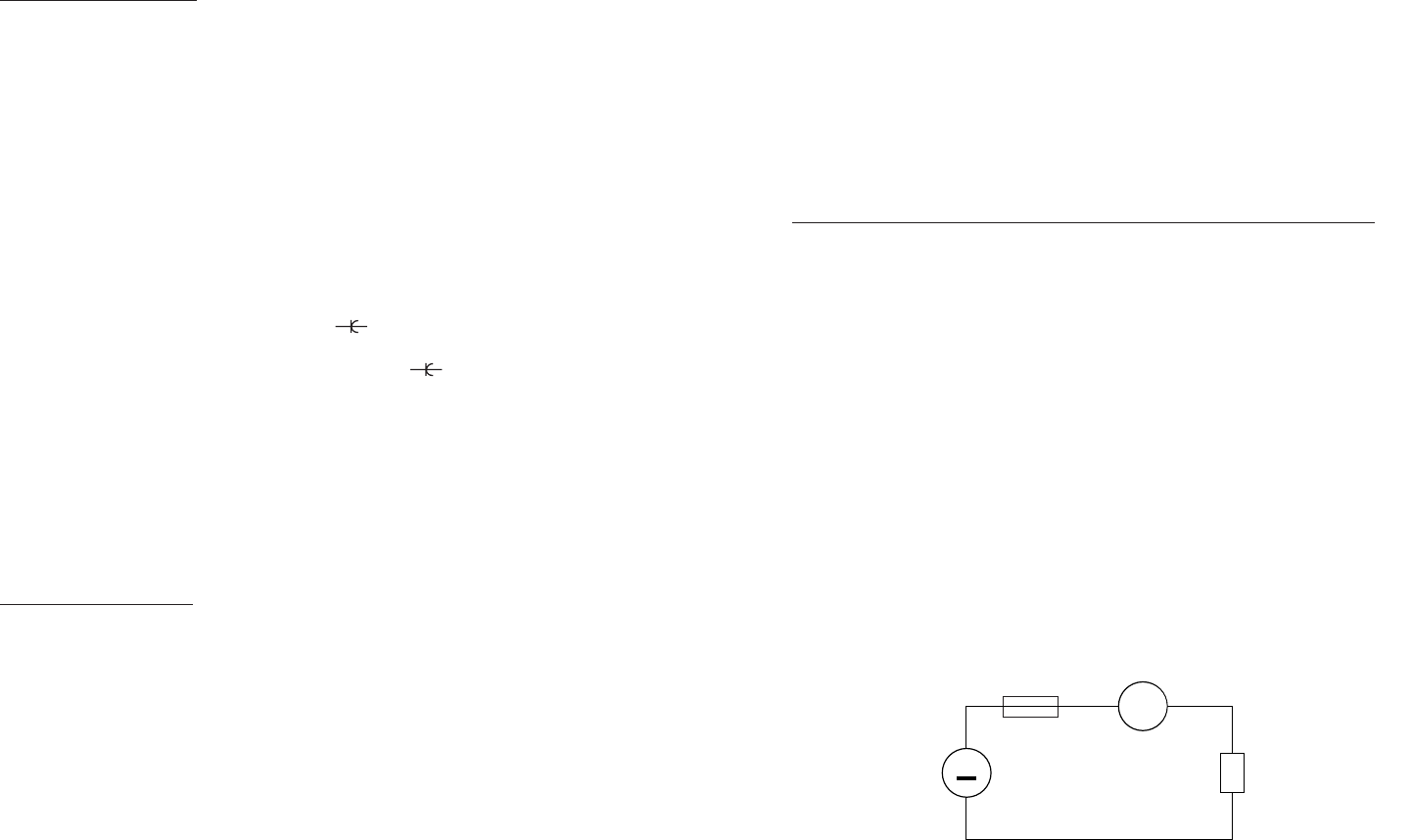
c) Relier les conduites de mesure en série avec l’objet à mesurer (voir l’illustration
suivante).
Attention !
Dès qu’un signe négatif „-“ précède la valeur de mesure de courant continu, le
courant mesuré est négatif (ou les conduites de mesure sont inversées).
Ne jamais dépasser les grandeurs d’entrée maximum valables pour chaque
entrée car cela entraîne la destruction du fusible.