a) Multimeter einschalten ...................................................................................................................................11
b) Spannungsmessung „V“ ...............................................................................................................................12
c) Strommessung „A“ ........................................................................................................................................12
a) HOLD-Funktion .............................................................................................................................................16
b) Displaybeleuchtung ......................................................................................................................................16
c) LED-Lampe .................................................................................................................................................. 16
10. Reinigung und Wartung ...................................................................................................................................... 17
a) Allgemein ......................................................................................................................................................17
b) Reinigung ..................................................................................................................................................... 17
c) Einsetzen und Wechseln der Batterie ..........................................................................................................18
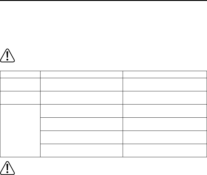
12. Behebung von Störungen ...................................................................................................................................21
Überschreiten Sie auf keinen Fall die max. zulässigen Eingangsgrößen. Berühren Sie keine
Schaltungen oder Schaltungsteile, wenn darin höhere Spannungen als 33 V/ACrms oder 70 V/DC
anliegen können! Lebensgefahr!
26
TABLE OF CONTENTS
G
Page
1. Operating elements ............................................................................................................................................ 27
3. Intended use .......................................................................................................................................................28
4. Scope of delivery ................................................................................................................................................29
5. Safety information ...............................................................................................................................................29
a) Switching on the multimeter ......................................................................................................................... 34
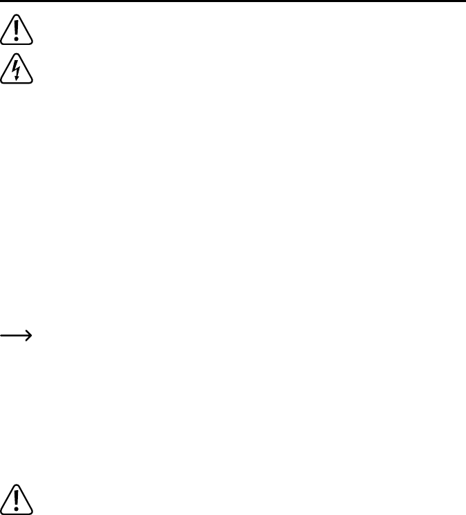
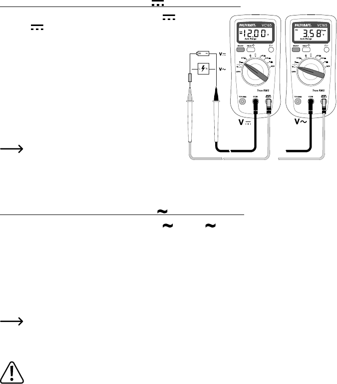
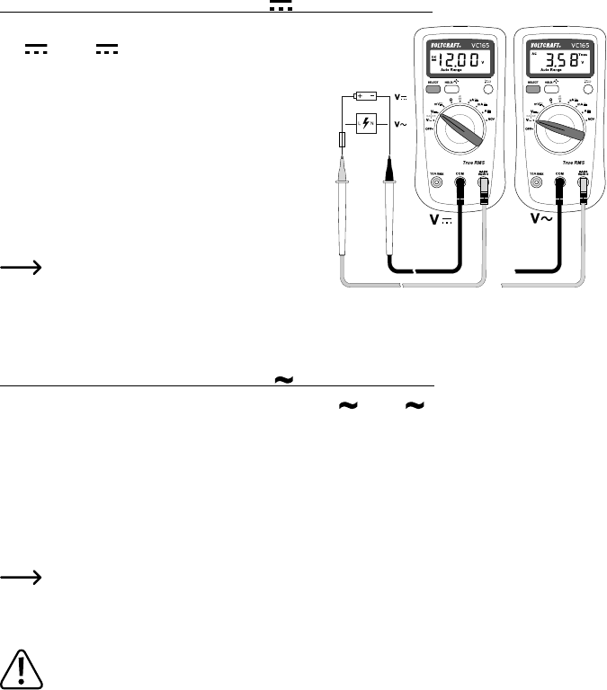
b) Voltage measuring “V” ..................................................................................................................................35
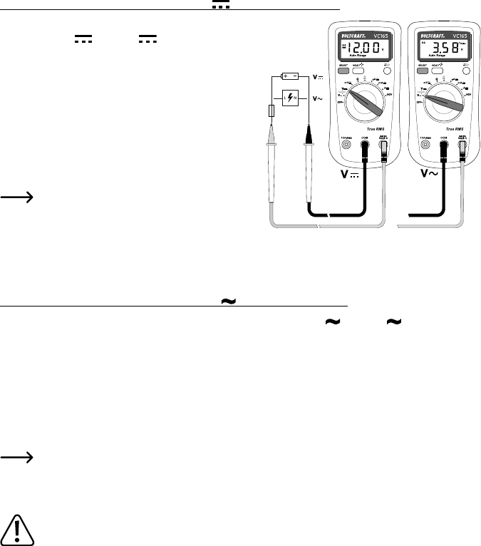
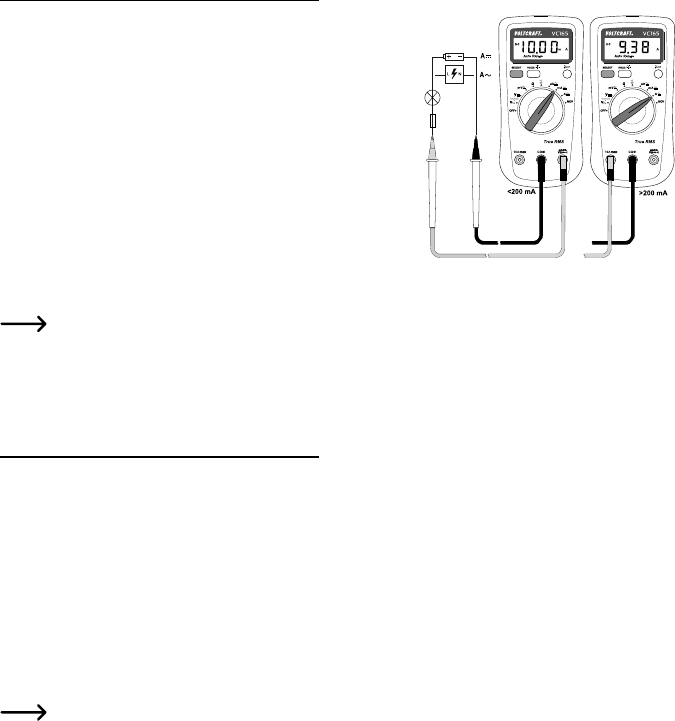
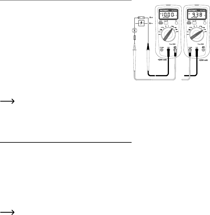
c) Current measuring “A“ ..................................................................................................................................35
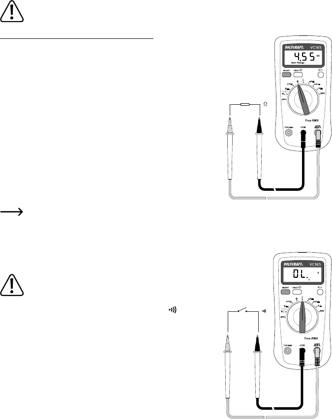
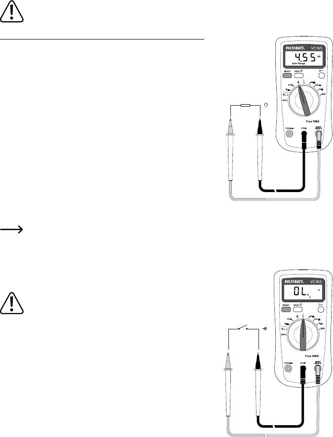
e) Acoustic continuity test ................................................................................................................................37
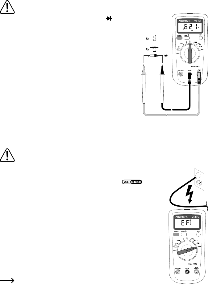
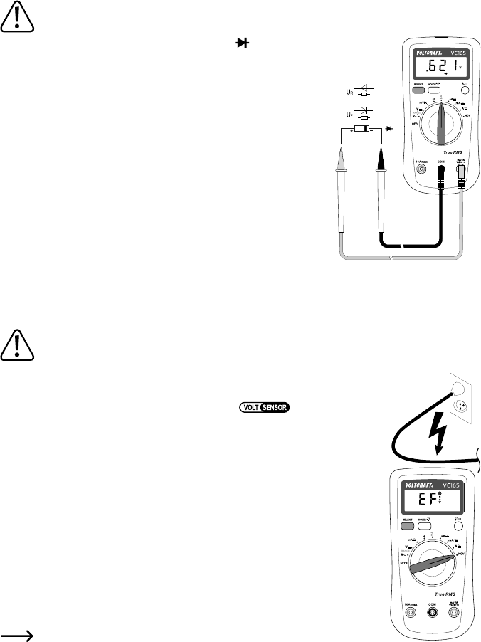
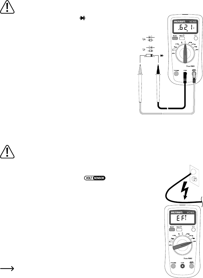
f) Diode test ..................................................................................................................................................... 38
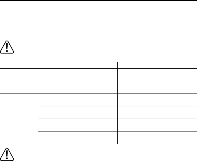
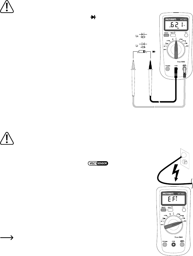
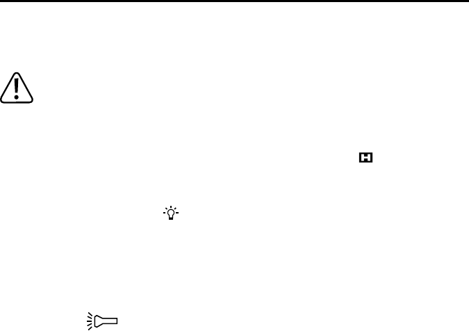
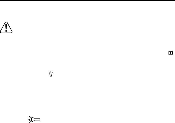
g) Contact-free AC voltage recognition (NCV) ..................................................................................................38
a) HOLD function ..............................................................................................................................................39
b) Display lighting ............................................................................................................................................. 39
c) LED lamp ......................................................................................................................................................39
10. Cleaning and maintenance .................................................................................................................................40
a) General information ......................................................................................................................................40
b) Cleaning ....................................................................................................................................................... 40
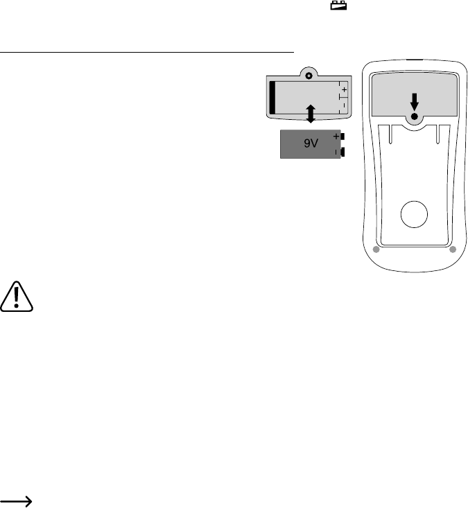
c) Inserting and changing the batteries ............................................................................................................ 41
13. Technical data .....................................................................................................................................................45
27
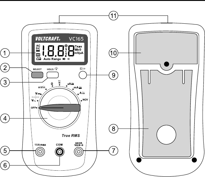
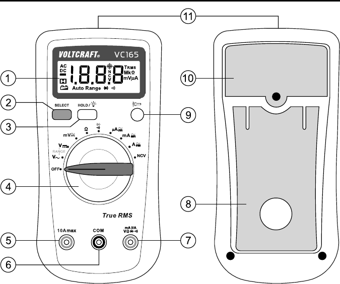
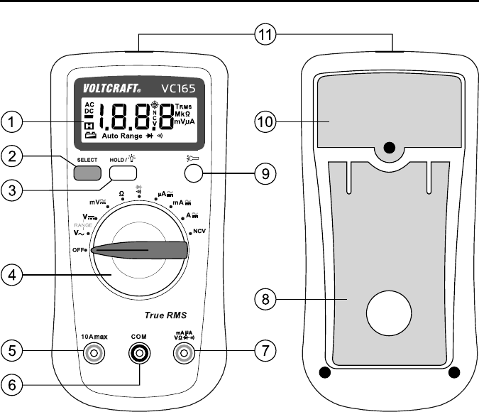
1. OPERATING ELEMENTS
1 Display
2 SELECT key to switch the functions marked in red at the dial switch
3 HOLD/display lighting key
Push briey to hold the measuring display
Push > 2 seconds to switch the display lighting on and off.
4 Dial switch for selecting the measuring function
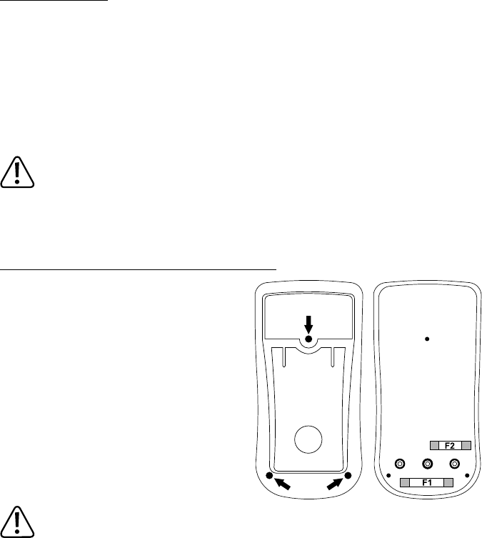
5 10 A-current measuring socket
6 COM measuring socket (reference potential, “minus potential”)
7 VΩmA measuring socket (“plus potential”)
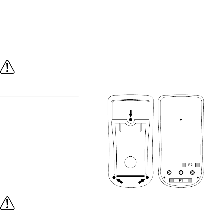
8 Setup bracket, unfolding
9 Pressure switch with latching function for LED lamp function
10 Battery compartment
11 Integrated LED lamp and NCV sensor
28
2. INTRODUCTION
Dear customer,
Thank you for making the excellent decision to purchase this Voltcraft
®
product.
You have acquired a quality product from a brand family which has distinguished itself in the elds of measuring,
charging and grid technology thanks to its particular expertise and its continuous innovation.
With Voltcraft
®
, you will be able to handle difcult tasks, either as an ambitious hobbyist or as a professional user.
Voltcraft
®
offers reliable technology and a great price-performance-ratio.
We are positive: Starting to work with Voltcraft
®
will also be the beginning of a long, successful relationship.
Enjoy your new Voltcraft
®
product!
If there are any technical questions, please contact:
www.conrad.com/contact
3. INTENDED USE
- Measuring and displaying electric parameters in the range of measurement category CAT III up to 600 V against
earth potential, pursuant to EN 61010-1 and all lower measuring categories. The meter must not be used in the
measuring category CAT IV.
- Measurement of direct and alternating voltage up to 600 V
- Measurement of direct and alternating current up to 10 A
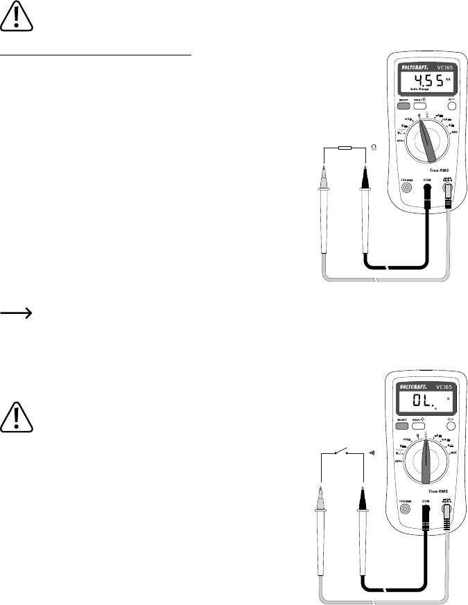
- Measurement of resistances up to 20 MΩ
- Acoustic continuity test (<50 Ω)
- Diode test
- Contact-free recognition of alternating voltage 220 V/AC, 50 - 60 Hz.
The measurement functions are selected using the dial switch. The measuring range is selected automatically for all
measuring functions (except for diode test, continuity test and NCV). Manual measuring range selection is possible
in the two V-measuring ranges (marked “RANGE”).
The VC165 shows actual effective measured values (True RMS) in the AC voltage and current measuring ranges.
Polarity is automatically indicated with the minus prex (-) if the measured values are negative.
Use of personal protection equipment is recommended for measurements in CAT III environments. The meter must
not be used in the measuring category CAT IV.
An integrated LED lamp can be used as a ashlight for dark areas.
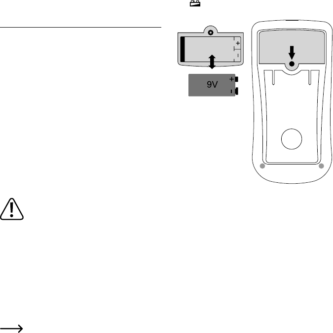
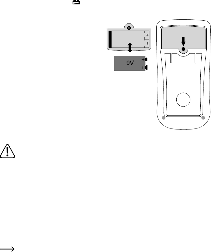
The multimeter is operated with a conventional 9 V block battery (type 6F22, NEDA1604 or same build). The device
must only be operated with the specied battery type. Rechargeable batteries should not be used because of the
lower capacity and the resulting shorter operating time.
The multimeter must not be operated when it is open, i.e. with an open battery compartment or when the battery
compartment cover is missing.
29
Measuring in potentially explosive areas (Ex) or damp rooms or under unfavourable ambient conditions is not
permitted. Unfavourable ambient conditions are: Moisture or high humidity, dust and ammable gases, fumes or
solvents, thunderstorms or thunderstorm conditions like strong electrostatic elds, etc.
For safety reasons, only use measuring lines or accessories which are adjusted to the specications of the multim-
eter when measuring.
The meter must only be operated by persons who are familiar with the required provisions for the measurement and
the possible dangers. Use of personal protection equipment is recommended.
Any use other than that described above will lead to damage to the product and involves additional risks such as, for
example, short circuit, re, electric shock, etc. No part of this product must be modied or converted!
Read the operating instructions carefully and keep them for later reference.
Always observe the safety information!
4. SCOPE OF DELIVERY
• Digital-Multimeter VC165
• 9 V block battery
• 2 safety measuring lines with removable CAT III cover caps
• Operating instructions
1Up-to-date Operating Instructions
Download the latest operating instructions at www.conrad.com/downloads or scan the QR code
shown. Follow the instructions on the website.
5. SAFETY INFORMATION
Please read the operating instructions completely before taking the device into operation. They
contain important information for correct operation.
The guarantee/warranty will expire if damage is incurred resulting from non-compliance with the
operating instructions! We do not assume any liability for consequential damage!
We do not assume any liability for damage to property or personal injury caused by improper use
or the failure to observe the safety instructions! In such cases the warranty/guarantee is voided.
This device left the manufacturer’s factory in safe and perfect condition.
To maintain this condition and to ensure safe operation, the user must observe the safety information and warning
notes in these operating instructions.
30
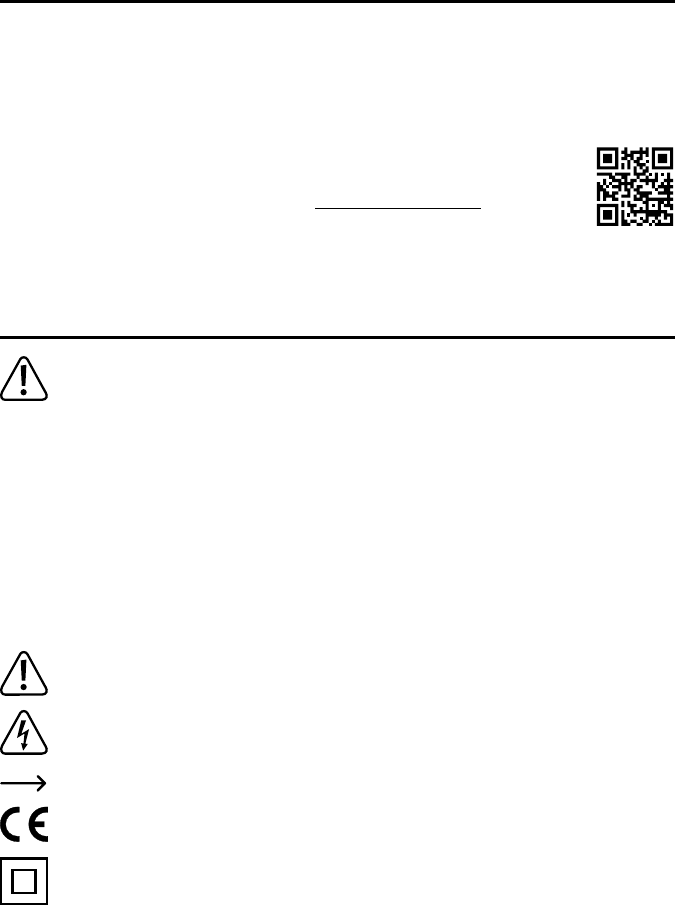
Observe the following symbols:
An exclamation mark in a triangle shows important notes in these operating instructions that must be
strictly observed.
The triangle containing a lightning symbol warns of danger of electrical shock or impairment of the electri-
cal safety of the device.
The arrow symbol indicates that special advice and notes on operation are provided.
This device is CE-compliant and meets the applicable European directives.
Protection class 2 (double or reinforced insulation, protective insulation)
CAT I Measuring category I for measurements at electrical and electronic devices that are not directly supplied
with mains voltage (e.g. battery-powered devices, protective low voltages, signal and control voltages,
etc.)
CAT II Measuring category II for measurements at electrical and electronic devices connected to the mains
supply directly with a mains plug. This category also covers all lower categories (e.g. CAT I for measuring
signal and control voltages).
CAT III Measuring category III for measuring in building installation (e.g. outlets or sub-distribution). This category
also covers all lower categories (e.g. CAT II for measuring electronic devices). Measuring operation in
CAT III is only permitted with measuring prods with a maximum free contact length of 4 mm or with cover
caps above the measuring prods.
CAT IV Measuring category IV for measurements at the source of the low-voltage installation (e.g. main distribu-
tion, building handover points of the energy suppliers, etc.), and outdoors (e.g. work at earthing cable,
outdoor line, etc.). This category also contains all lower categories. Measuring operation in CAT IV is only
permitted with measuring prods with a maximum free contact length of 4 mm or with cover caps above
the measuring prods.
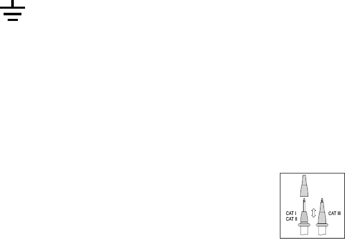
Earth potential
For safety and approval reasons, unauthorised conversion and/or modication of the device are not permitted.
Consult an expert when in doubt as to the operation, safety or the connection of the device.
Meters and accessories are not toys and have no place in the hands of children!
In commercial institutions, the accident prevention regulations of the Employer’s Liability Insurance Association for
Electrical Systems and Operating Materials are to be observed.
In schools, training centres, computer and self-help workshops, handling of meters must be supervised by trained
personnel in a responsible manner.
Ensure before every measurement that the meter is not set to another measuring range. Also observe that the
HOLD button has not been pushed at the beginning of the measurement (display with the HOLD button pushed:
“H”). If the HOLD function is activated before commencement of the measurement, no measured value is displayed!
31
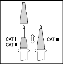
When using the measuring lines without cover caps, measurements between the meter and
the earth potential must not be performed above the measuring category CAT II.
When measuring in the measuring category CAT III, the cover caps must be pushed onto the
measuring prods to avoid accidental short circuits during measurement.
Push the cover caps onto the measuring prods until they latch. To remove, pull the caps from
the prods with a little force.
The measuring prods have to be removed from the measured object every time the measuring range is changed.
The voltage between the connection points of the meter and earth potential must not exceed 600 V DC/AC in
CAT III.
Be especially careful when dealing with voltages higher than 33 V alternating (AC) or 70 V direct voltage (DC)! Even
at these voltages it is possible to receive a potentially fatal electric shock if you touch electrical conductors.
To avoid electric shock, make sure not to touch the connections/measuring points to be measured directly or
indirectly during measurement. Never reach beyond the noticeable grip area marks at the measuring prods during
measurements.
Check the meter and its measuring lines for damage before each measurement. Never carry out any measurements
if the protecting insulation is defective (torn, ripped off etc.). The enclosed measuring cables have a wear indicator.
When they are damaged, a second insulation layer in a different colour becomes visible. The measuring accessories
must no longer be used and must be replaced.
Do not use the multimeter just before, during or just after a thunderstorm (lightning! / high-energy overvoltage!).
Make sure that your hands, shoes, clothing, the oor, circuits and circuit components are dry.
Never operate the product in direct proximity of:
- strong magnetic or electromagnetic elds
- Transmitter aerials or HF generators.
This could affect the measurement.
If you have reason to believe that the device can no longer be operated safely, disconnect it immediately and make
sure it is not operated unintentionally. It can be assumed that safe operation is no longer possible if:
- the device shows visible damage
- the device no longer functions
- the device was stored under unfavourable conditions over an extended period of time or
- following considerable stress during transportation.
Do not switch the meter on immediately after it was taken from a cold to a warm environment. The condensation
that forms might destroy your device. Allow the device to reach room temperature before switching it on.
Do not leave the packaging material lying around carelessly since such materials can become dangerous toys in the
hands of children.
Also observe the safety information in each chapter of these instructions.
32
6. PRODUCT DESCRIPTION
The multimeter (referred to as DMM in the following) indicates measured values on a digital display that can be
illuminated. The measured value display of the DMM comprises 2000 counts (count = smallest display value).
The meter can be used for do-it-yourself or for professional applications up to CAT III.
There are transport protection caps in the angled plugs of the enclosed measuring lines. Remove them before push-
ing the plugs into the meter sockets.
At the rear, there is an unfolding setup bracket (8) with which the DMM can be set up inclined. This makes it easier
to read the display.
An automatic deactivation function switches off the multimeter independently if it is not used for an extended period.
This protects the battery and extends its service life.
Every time the dial switch is pushed and the function is switched, there will be a beep for conrmation.
Dial switch (4)
The individual measuring functions and ranges are selected via a dial switch.
If the multimeter switch is set to “OFF”, the meter is switched off. Always turn the meter off when it is not in use.
33
7. DISPLAY INDICATIONS AND SYMBOLS
The following symbols and information are present at the device or in the display.
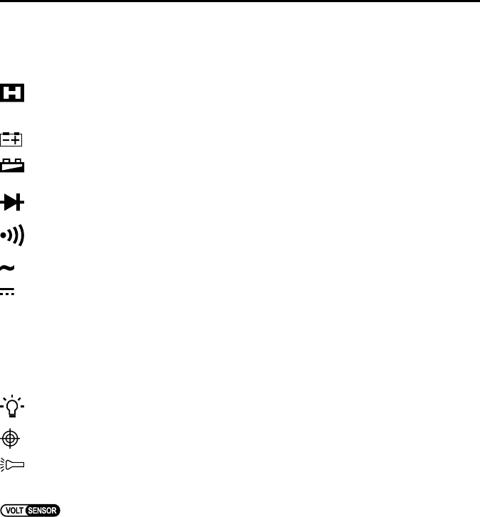
OFF Switch position “off”
HOLD Call/deactivate data hold function
Data-Hold function is active
OL. Overow display, the measuring area was exceeded
Symbol for the battery data used
Battery change symbol. When this symbol appears in the display, the battery must be replaced at
once to avoid measuring errors!
Symbol for the diode test
Symbol for the acoustic continuity tester
AC Symbol for alternating current
DC Symbol for direct current
V, mV Volt (unit of electric voltage), Milli-Volt (exp.-3)
Do not exceed the maximum permitted input values. Do not touch any circuits or parts of circuits
if they may be subject to voltages higher than 33 V/ACrms or 70 V/DC! Danger to life!
49
TABLE DES MATIÈRES
F
Page
1. Éléments de commande .....................................................................................................................................50
4. Étendue de la livraison ....................................................................................................................................... 53
5. Consignes de sécurité ........................................................................................................................................ 53
6. Description du produit .........................................................................................................................................56
7. Indications et symboles sur l’écran .....................................................................................................................57
8. Mode de mesure .................................................................................................................................................58
a) Mise en marche du multimètre ..................................................................................................................... 58
b) Mesure de tension « V » ...............................................................................................................................59
c) Mesure du courant « A » ...............................................................................................................................59
d) Mesure des résistances ...............................................................................................................................61
e) Essai de continuité acoustique ....................................................................................................................61
f) Test des diodes .............................................................................................................................................62
g) Détection sans contact de la tension CA « NCV » ....................................................................................... 62
a) Fonction HOLD .............................................................................................................................................63
b) Éclairage de l’indicateur ............................................................................................................................... 63
c) Lampe DEL ...................................................................................................................................................63
10. Entretien et nettoyage .........................................................................................................................................64
a) Généralités ...................................................................................................................................................64
b) Nettoyage .....................................................................................................................................................64
c) Mise en place et remplacement des piles .................................................................................................... 65
d) Remplacement des fusibles ......................................................................................................................... 66
3. Voorgeschreven gebruik .....................................................................................................................................76
a) Multimeter inschakelen .................................................................................................................................82
b) Spanningsmeting “V” ....................................................................................................................................83
c) Stroommeting “A” ......................................................................................................................................... 83
a) HOLD-functie ................................................................................................................................................87
b) Schermverlichting .........................................................................................................................................87
c) LED-lamp ......................................................................................................................................................87
10. Reiniging en onderhoud ......................................................................................................................................88
a) Algemeen ..................................................................................................................................................... 88
b) Reiniging .......................................................................................................................................................88
c) Plaatsen en vervangen van de batterij .........................................................................................................89
d) Vervangen van zekeringen ...........................................................................................................................90
12. Verhelpen van storingen .....................................................................................................................................92
Gebruikershandleiding.com neemt misbruik van zijn services uitermate serieus. U kunt hieronder aangeven waarom deze vraag ongepast is. Wij controleren de vraag en zonodig wordt deze verwijderd.
Product:
Spelregels forum
Om tot zinvolle vragen te komen hanteren wij de volgende spelregels:
lees eerst de handleiding door;
controleer of uw vraag al eerder door iemand anders is gesteld;
probeer uw vraag zo duidelijk mogelijk te stellen;
heeft u een probleem en al geprobeerd om dit op te lossen, vermeld dit erbij aub;
heeft u een oplossing gekregen van een bezoeker dan horen wij dat graag in dit forum;
wilt u een reactie geven op een vraag of antwoord, gebruik dan niet dit formulier maar klik op de knop 'reageer op deze vraag';
uw vraag wordt direct op de website gezet; vermijd daarom persoonlijke gegevens in te vullen;
Belangrijk! Als er een antwoord wordt gegeven op uw vraag, dan is het voor de gever van het antwoord nuttig om te weten als u er wel (of niet) mee geholpen bent! Wij vragen u dus ook te reageren op een antwoord.
Belangrijk! Antwoorden worden ook per e-mail naar abonnees gestuurd. Laat uw emailadres achter op deze site, zodat u op de hoogte blijft. U krijgt dan ook andere vragen en antwoorden te zien.
Abonneren
Abonneer u voor het ontvangen van emails voor uw Voltcraft VC165 bij:
nieuwe vragen en antwoorden
nieuwe handleidingen
U ontvangt een email met instructies om u voor één of beide opties in te schrijven.
Ontvang uw handleiding per email
Vul uw emailadres in en ontvang de handleiding van Voltcraft VC165 in de taal/talen: Nederlands, Duits, Engels, Frans als bijlage per email.
De handleiding is 1,82 mb groot.
U ontvangt de handleiding per email binnen enkele minuten. Als u geen email heeft ontvangen, dan heeft u waarschijnlijk een verkeerd emailadres ingevuld of is uw mailbox te vol. Daarnaast kan het zijn dat uw internetprovider een maximum heeft aan de grootte per email. Omdat hier een handleiding wordt meegestuurd, kan het voorkomen dat de email groter is dan toegestaan bij uw provider.
Stel vragen via chat aan uw handleiding
Stel uw vraag over deze PDF
Uw handleiding is per email verstuurd. Controleer uw email
Als u niet binnen een kwartier uw email met handleiding ontvangen heeft, kan het zijn dat u een verkeerd emailadres heeft ingevuld of dat uw emailprovider een maximum grootte per email heeft ingesteld die kleiner is dan de grootte van de handleiding.
Er is een email naar u verstuurd om uw inschrijving definitief te maken.
Controleer uw email en volg de aanwijzingen op om uw inschrijving definitief te maken
U heeft geen emailadres opgegeven
Als u de handleiding per email wilt ontvangen, vul dan een geldig emailadres in.
Uw vraag is op deze pagina toegevoegd
Wilt u een email ontvangen bij een antwoord en/of nieuwe vragen? Vul dan hier uw emailadres in.