579970
13
Verklein
Vergroot
Pagina terug
1/90
Pagina verder

D
BEDIENUNGSANLEITUNG SEITE 1 - 23

G
OPERATING INSTRUCTIONS PAGE 24 - 44

F
NOTICE DEMPLOI PAGE 45 - 65

O
GEBRUIKSAANWIJZING PAGINA 66 - 89
Best.-Nr. / Item no. /
N° de commande / Bestelnr.:
1214405
VERSION 05/15

D

1. EINFÜHRUNG ..................................................................................................................................................... 4
2. BESTIMMUNGSGEMÄSSE VERWENDUNG ..................................................................................................... 5
3. BEDIENELEMENTE ............................................................................................................................................ 6
4. LIEFERUMFANG ................................................................................................................................................. 6
5. SICHERHEITSHINWEISE ................................................................................................................................... 6
6. PRODUKTBESCHREIBUNG .............................................................................................................................. 9
7. DISPLAY-ANGABEN UND SYMBOLE .............................................................................................................. 10
8. MESSBETRIEB ..................................................................................................................................................11
a) Multimeter einschalten ..................................................................................................................................11
b) Spannungsmessung „V“ .............................................................................................................................. 12
c) Gleichstrommessung „A DC“ ....................................................................................................................... 13
d) Gleichstrommessung „mA/µA DC“ .............................................................................................................. 14
e) Widerstandsmessung .................................................................................................................................. 15
f) Akustische Durchgangsprüfung ................................................................................................................... 15
g) Diodentest ................................................................................................................................................... 16
h) Batterietest .................................................................................................................................................. 16
9. ZUSATZFUNKTIONEN ...................................................................................................................................... 17
a) HOLD-Funktion ............................................................................................................................................ 17
b) Displaybeleuchtung ..................................................................................................................................... 17
10. REINIGUNG UND WARTUNG .......................................................................................................................... 17
a) Allgemein .....................................................................................................................................................17
b) Reinigung .................................................................................................................................................... 18
c) Einsetzen und Wechseln der Batterie ......................................................................................................... 18
d) Sicherungswechsel ...................................................................................................................................... 19
11. ENTSORGUNG ................................................................................................................................................. 20
12. BEHEBUNG VON STÖRUNGEN ...................................................................................................................... 20
13. TECHNISCHE DATEN ...................................................................................................................................... 21

Sehr geehrter Kunde,
mit diesem Voltcraft
®
-Produkt haben Sie eine sehr gute Entscheidung getroffen, für die wir Ihnen danken möchten.
Sie haben ein überdurchschnittliches Qualitätsprodukt aus einer Marken-Familie erworben, die sich auf dem Gebiet
der Mess-, Lade- und Netztechnik durch besondere Kompetenz und permanente Innovation auszeichnet.
Mit Voltcraft
®
werden Sie als anspruchsvoller Bastler ebenso wie als professioneller Anwender auch schwierigen
Aufgaben gerecht. Voltcraft
®
bietet Ihnen zuverlässige Technologie zu einem außergewöhnlich günstigen Preis-
Leistungs-Verhältnis.
Wir sind uns sicher: Ihr Start mit Voltcraft ist zugleich der Beginn einer langen und guten Zusammenarbeit.
Viel Spaß mit Ihrem neuen Voltcraft
®
-Produkt!

Deutschland: www.conrad.de/kontakt
Österreich: www.conrad.at
www.business.conrad.at
Schweiz: www.conrad.ch
www.biz-conrad.ch

- Messen und Anzeigen der elektrischen Größen im Bereich der Messkategorie CAT III bis max. 600 V gegen
Erdpotential, gemäß EN 61010-1 sowie alle niedrigeren Messkategorien. Das Messgerät darf nicht in der Messka-
tegorie CAT IV eingesetzt werden.
- Messen von Gleich- und Wechselspannung bis max. 600 V
- Messen von Gleichstrom bis max. 10 A
- Messen von Widerständen bis 2000 kΩ
- Akustische Durchgangsprüfung (<30 Ω)
- Diodentest
- Batterietest für 9 V-Block- und 1,5 V Rundzellen-Batterien
Die Messfunktionen werden über den Drehschalter angewählt. Die Messbereichswahl erfolgt in allen Messfunktio-
nen manuell.
Beim VC-125 werden im AC-Spannungsmessbereich Mittelwerte angezeigt. Die Polarität wird bei negativem Mess-
wert automatisch mit Minus-Vorzeichen (-) dargestellt.
Die Anwendung einer persönlichen Schutzausrüstung ist für Messungen in CAT III Umgebung empfehlenswert. Das
Messgerät darf nicht in der Messkategorie CAT IV eingesetzt werden.
Betrieben wird das Multimeter mit einer handelsüblichen 9V Block-Batterien (Typ 6F22, NEDA1604 oder baugleich).
Der Betrieb ist nur mit dem angegebenen Batterietyp zulässig. Akkus sollten aufgrund der geringeren Kapazität und
der daraus resultierenden kürzeren Betriebszeit nicht verwendet werden.
Das Multimeter darf im geöffneten Zustand, mit geöffnetem Batteriefach oder fehlendem Batteriefachdeckel nicht
betrieben werden.
Messungen in explosionsgefährdeten Bereichen (Ex) oder Feuchträumen bzw. unter widrigen Umgebungsbedin-
gungen sind nicht zulässig. Widrige Umgebungsbedingungen sind: Nässe oder hohe Luftfeuchtigkeit, Staub und
brennbare Gase, Dämpfe oder Lösungsmittel sowie Gewitter bzw. Gewitterbedingungen wie starke elektrostatische
Felder usw.
Verwenden Sie zum Messen nur Messleitungen bzw. Messzubehör, welche auf die Spezikationen des Multimeters
abgestimmt sind.
Das Messgerät darf nur von Personen bedient werden, welche mit den erforderlichen Vorschriften für die Messung
und den möglichen Gefahren vertraut sind. Die Verwendung der persönlichen Schutzausrüstung wird empfohlen.
Eine andere Verwendung als zuvor beschrieben, führt zur Beschädigung dieses Produktes, außerdem ist dies
mit Gefahren wie z.B. Kurzschluss, Brand, elektrischer Schlag etc. verbunden. Das gesamte Produkt darf nicht
geändert bzw. umgebaut werden!
Lesen Sie die Bedienungsanleitung sorgfältig durch, und bewahren Sie diese für späteres Nachschlagen auf.
Die Sicherheitshinweise sind unbedingt zu beachten!

1 Display
2 HOLD-Taste mit Rastfunktion zum Festhalten der Messanzeige
3 Drehschalter zur Messfunktionswahl
4 10 A-Strommessbuchse
5 COM-Messbuchse (Bezugspotenzial, „Minuspotenzial“)
6 VΩmA-Messbuchse („Pluspotenzial“)
7 Aufstellbügel ausklappbar
8 Batteriefach
9 Taste für Displaybeleuchtung

Digital-Multimeter VC-125
9V Block-Batterie
2 Sicherheitsmessleitungen mit abnehmbaren CAT III Abdeckkappen
Bedienungsanleitung








Dieses Gerät hat das Werk in sicherheitstechnisch einwandfreien Zustand verlassen.
Um diesen Zustand zu erhalten und einen gefahrlosen Betrieb sicherzustellen, muss der Anwender die Sicherheits-
hinweise und Warnvermerke beachten, die in dieser Gebrauchsanweisung enthalten sind.

Ein in einem Dreieck bendliches Ausrufezeichen weist auf wichtige Hinweise in dieser Bedienungsanlei-
tung hin, die unbedingt zu beachten sind.
Ein Blitzsymbol im Dreieck warnt vor einem elektrischen Schlag oder der Beeinträchtigung der elektri-
schen Sicherheit des Geräts.
Das „Pfeil“-Symbol ist zu nden, wenn Ihnen besondere Tipps und Hinweise zur Bedienung gegeben werden
sollen.
Dieses Gerät ist CE-konform und erfüllt die erforderlichen nationalen und europäischen Richtlinien
Schutzklasse 2 (doppelte oder verstärkte Isolierung, schutzisoliert).
Achtung Anleitung lesen.
 Messkategorie I für Messungen an elektrischen und elektronischen Geräten, welche nicht direkt mit
Netzspannung versorgt werden (z.B. batteriebetriebene Geräte, Schutzkleinspannung, Signal- und
Steuerspannungen etc.)
 Messkategorie II für Messungen an elektrischen und elektronischen Geräten, welche über einen Netzste-
cker direkt mit Netzspannung versorgt werden. Diese Kategorie umfasst auch alle kleineren Kategorien
(z.B. CAT I zur Messung von Signal- und Steuerspannungen).
 Messkategorie III für Messungen in der Gebäudeinstallation (z.B. Steckdosen oder Unterverteilungen).
Diese Kategorie umfasst auch alle kleineren Kategorien (z.B. CAT II zur Messung an Elektrogeräten). Der
Messbetrieb in CAT III ist nur mit Messspitzen mit einer maximalen freien Kontaktlänge von 4 mm bzw.
mit Abdeckkappen über den Messspitzen zulässig.
 Messkategorie IV für Messungen an der Quelle der Niederspannungsinstallation (z.B. Hauptverteilung,
Haus-Übergabepunkte der Energieversorger etc.) und im Freien (z.B. Arbeiten an Erdkabel, Freileitung
etc.). Diese Kategorie umfasst auch alle kleineren Kategorien. Der Messbetrieb in CAT IV ist nur mit
Messspitzen mit einer maximalen freien Kontaktlänge von 4 mm bzw. mit Abdeckkappen über den Mess-
spitzen zulässig.
Erdpotential
Aus Sicherheits- und Zulassungsgründen (CE) ist das eigenmächtige Umbauen und/oder Verändern des Gerätes
nicht gestattet.
Wenden Sie sich an eine Fachkraft, wenn Sie Zweifel über die Arbeitsweise, die Sicherheit oder den Anschluss des
Gerätes haben.
Messgeräte und Zubehör sind kein Spielzeug und gehören nicht in Kinderhände!
In gewerblichen Einrichtungen sind die Unfallverhütungsvorschriften des Verbandes der gewerblichen Berufsgenos-
senschaften für elektrische Anlagen und Betriebsmittel zu beachten.
In Schulen und Ausbildungseinrichtungen, Hobby- und Selbsthilfewerkstätten ist der Umgang mit Messgeräten
durch geschultes Personal verantwortlich zu überwachen.
Stellen Sie vor jeder Messung sicher, dass sich das Messgerät nicht in einem anderen Messbereich bendet. Ach-
ten Sie ebenso darauf, dass die HOLD-Taste zu Messbeginn nicht gedrückt wurde (Displayanzeige bei gedrückter
HOLD-Taste „HOLD“). Bei gedrückter HOLD-Taste zu Messbeginn, wird kein Messwert angezeigt!
Bei Verwendung der Messleitungen ohne Abdeckkappen dürfen Messungen zwischen
Messgerät und Erdpotential nicht oberhalb der Messkategorie CAT II durchgeführt
werden.
Bei Messungen in der Messkategorie CAT III müssen die Abdeckkappen auf die
Messspitzen gesteckt werden, um versehentliche Kurzschlüsse während der Messung
zu vermeiden.
Stecken Sie die Abdeckkappen auf die Messspitzen, bis diese Einrasten. Zum Entfernen
ziehen Sie die Kappen mit etwas Kraft von den Spitzen.
Vor jedem Wechsel des Messbereiches sind die Messspitzen vom Messobjekt zu entfernen.
Die Spannung zwischen den Anschlusspunkten des Messgeräts und Erdpotential darf 600 V DC/AC in CAT III nicht
überschreiten.
Seien Sie besonders Vorsichtig beim Umgang mit Spannungen >33 V Wechsel- (AC) bzw. >70 V Gleichspannung
(DC)! Bereits bei diesen Spannungen können Sie bei Berührung elektrischer Leiter einen lebensgefährlichen
elektrischen Schlag erhalten.
Um einen elektrischen Schlag zu vermeiden, achten Sie darauf, dass Sie die zu messenden Anschlüsse/Messpunk-
te während der Messung nicht, auch nicht indirekt, berühren. Über die fühlbaren Griffbereichsmarkierungen an den
Messspitzen darf während des Messens nicht gegriffen werden.
Überprüfen Sie vor jeder Messung Ihr Messgerät und deren Messleitungen auf Beschädigung(en). Führen Sie auf
keinen Fall Messungen durch, wenn die schützende Isolierung beschädigt (eingerissen, abgerissen usw.) ist. Die
beiliegenden Messkabel haben einen Verschleißindikator. Bei einer Beschädigung wird eine zweite, andersfarbige
Isolierschicht sichtbar. Das Messzubehör darf nicht mehr verwendet werden und muss ausgetauscht werden.
Verwenden Sie das Multimeter nicht kurz vor, während oder kurz nach einem Gewitter (Blitzschlag! / energiereiche
Überspannungen!). Achten Sie darauf, dass ihre Hände, Schuhe, Kleidung, der Boden, Schaltungen und Schal-
tungsteile usw. unbedingt trocken sind.
Vermeiden Sie den Betrieb in unmittelbarer Nähe von:
- starken magnetischen oder elektromagnetischen Feldern
- Sendeantennen oder HF-Generatoren.
Dadurch kann der Messwert verfälscht werden.
Wenn anzunehmen ist, dass ein gefahrloser Betrieb nicht mehr möglich ist, so ist das Gerät außer Betrieb zu
setzen und gegen unbeabsichtigten Betrieb zu sichern. Es ist anzunehmen, dass ein gefahrloser Betrieb nicht mehr
möglich ist, wenn:
- das Gerät sichtbare Beschädigungen aufweist,
- das Gerät nicht mehr arbeitet und
- nach längerer Lagerung unter ungünstigen Verhältnissen oder
- nach schweren Transportbeanspruchungen.
Schalten Sie das Messgerät niemals gleich dann ein, wenn dieses von einem kalten in einen warmen Raum
gebracht wird. Das dabei entstandene Kondenswasser kann unter Umständen Ihr Gerät zerstören. Lassen Sie das
Gerät uneingeschaltet auf Zimmertemperatur kommen.
Lassen Sie das Verpackungsmaterial nicht achtlos liegen; dieses könnte für Kinder zu einem gefährlichen Spielzeug
werden.
Beachten Sie auch die Sicherheitshinweise in den einzelnen Kapiteln.

Die Messwerte werden am Multimeter (im folgendem DMM genannt) in einer beleuchtbaren Digitalanzeige darge-
stellt. Die Messwertanzeige des DMM umfasst 2000 Counts (Count = kleinster Anzeigewert).
Das Messgerät ist sowohl im Hobby- als auch im professionellen Bereich bis CAT III einsetzbar.
In den abgewinkelten Steckern der beiliegenden Messleitungen benden sich Transportschutzkappen. Entfernen
Sie diese, bevor Sie die Stecker in die Messgeräte-Buchsen stecken.
An der Rückseite ist ein ausklappbarer Aufstellbügel (7) vorhanden, mit dem das DMM in eine schräge Position
gestellt werden kann. Dies erleichtert die Ablesung des Displays.

Die einzelnen Messfunktionen und Messbereiche werden über einen Drehschalter angewählt.
Das Multimeter ist in der Schalterposition „OFF“ ausgeschaltet. Schalten Sie das Messgerät bei Nichtgebrauch
immer aus.


Folgende Symbole und Angaben sind am Gerät oder im Display vorhanden.
OFF Schalterstellung „Aus“
HOLD Data-Hold-Funktion aufrufen/abschalten. Data-Hold-Funktion ist aktiv
OL Überlauf-Anzeige; der Messbereich wurde überschritten
Batteriewechselsymbol. Erscheint dieses Symbol im Display, muss umgehendst die Batterie gewech-
selt werden, um Messfehler zu vermeiden!
Symbol für die verwendeten Batteriedaten
Symbol für den Diodentest
Symbol für den akustischen Durchgangsprüfer
AC Symbol für Wechselstrom
DC Symbol für Gleichstrom
V, mV Volt (Einheit der elektrischen Spannung), Milli-Volt (exp.–3)
A, mA, µA Ampére (Einheit der elektrischen Stromstärke),
Milli-Ampére (exp.–3), Micro-Ampére (exp.–6)
Ω, kΩ Ohm (Einheit des elektrischen Widerstandes), Kilo-Ohm (exp.3)
Taste zur Ein- und Ausschaltung der Displaybeleuchtung
Symbol für die verwendeten Sicherungen
BATT. Messfunktion für Batterietest





















Beginnen Sie die Messungen immer mit dem größten Messbereich. Schalten Sie danach bei Bedarf in den
nächst kleineren Messbereich. Vor einem Messbereichswechsel immer die Messspitzen vom Messobjekt
entfernen. Sobald „OL“ (= Überlauf) erscheint, haben Sie den Messbereich überschritten.

Das Multimeter wird über den Drehschalter ein- und ausgeschaltet. Drehen Sie den Drehschalter (3) in die
entsprechende Messfunktion. Zum Ausschalten bringen Sie den Drehschalter in Position „OFF“. Schalten Sie das
Messgerät bei Nichtgebrauch immer aus.





 
- Schalten Sie das DMM ein und wählen den entsprechenden
Messbereich „V DC“.
- Stecken Sie die rote Messleitung in die V-Messbuchse (6), die
schwarze Messleitung in die COM-Messbuchse (5).
- Verbinden Sie die beiden Messspitzen mit dem Messobjekt (Batte-
rie, Schaltung usw.). Die rote Messspitze entspricht dem Pluspol,
die schwarze Messspitze dem Minuspol.
- Der aktuelle Messwert wird im Display angezeigt.
- Entfernen Sie nach Messende die Messleitungen vom Messobjekt
und schalten Sie das DMM aus.
Sobald bei der Gleichspannung ein Minus „-“ vor dem Messwert erscheint, ist die gemessene Spannung
negativ (oder die Messleitungen sind vertauscht).
Der Spannungsbereich „V DC“ weist einen Eingangswiderstand von >1 MOhm auf.


- Schalten Sie das DMM ein und wählen den entsprechenden Messbereich „V AC“.
-
Stecken Sie die rote Messleitung in die V-Messbuchse (6), die schwarze Messleitung in die COM-Messbuchse (5).
- Verbinden Sie die beiden Messspitzen mit dem Messobjekt (Generator, Netzspannung usw.).
- Der aktuelle Messwert wird im Display angezeigt.
- Entfernen Sie nach Messende die Messleitungen vom Messobjekt und schalten Sie das DMM aus.
Der Spannungsbereich „V AC“ weist einen Eingangswiderstand von >1 MΩ auf.




Die Strommessung erfolgt immer in Reihe zum Verbraucher. Vor dem Anschluss des Messgerätes muss der
Stromkreis stromlos geschaltet werden. Nach Messende immer erst den Messkreis stromlos schalten, bevor die
Messleitungen entfernt werden. Dies verhindert die Entstehung von Lichtbögen.
Strommessungen >5 A dürfen max. für 30 Sekunden und mit einer Messpause von mind. 15 Minuten durchgeführt
werden.


- Schalten Sie das DMM am Drehschalter (3) ein und wählen den
Messbereich „10 A“.
-
Stecken Sie die rote Messleitung in die 10A-Messbuchse (4), die
schwarze Messleitung in die COM-Messbuchse (5).
- Verbinden Sie die beiden Messspitzen in Reihe zum Verbraucher.
Die rote Messspitze entspricht dem Pluspol, die schwarze Messspit-
ze dem Minuspol. Schalten Sie den Mess-Stromkreis ein.
- Der Messwert wird im Display angezeigt.
Sobald bei Gleichstrommessung ein Minus „-„ vor dem Mess-
wert erscheint, verläuft der Strom entgegengesetzt (oder die
Messleitungen sind vertauscht).
- Schalten Sie nach Messende den Messkreis stromlos und entfernen Sie die Messspitzen vom Messobjekt. Schal-
ten Sie das Gerät aus. Drehen Sie den Drehschalter in Position „OFF“.




Die Strommessung erfolgt immer in Reihe zum Verbraucher. Vor dem Anschluss des Messgerätes muss der
Stromkreis stromlos geschaltet werden. Nach Messende immer erst den Messkreis stromlos schalten, bevor die
Messleitungen entfernt werden. Dies verhindert die Entstehung von Lichtbögen.
Der Innenwiderstand des Messgerätes verursacht durch die integrierte Sicherung im mA-Messbereich einen gerin-
gen Spannungsabfall im Messkreis (max. 200 mV), der jedoch meist zu vernachlässigen ist.


- Schalten Sie das DMM am Drehschalter (3) ein und wählen den entsprechenden Messbereich „mA/µA“.
-
Stecken Sie die rote Messleitung in die mA-Messbuchse (6), die schwarze Messleitung in die COM-Messbuchse (5).
- Verbinden Sie die beiden Messspitzen in Reihe zum Verbraucher. Die rote Messspitze entspricht dem Pluspol, die
schwarze Messspitze dem Minuspol. Schalten Sie den Mess-Stromkreis ein.
- Der Messwert wird im Display angezeigt.
Sobald bei Gleichstrommessung ein Minus „-„ vor dem Messwert erscheint, verläuft der Strom entgegenge-
setzt (oder die Messleitungen sind vertauscht).
- Schalten Sie nach Messende den Messkreis stromlos und entfernen Sie die Messspitzen vom Messobjekt. Schal-
ten Sie das Gerät aus. Drehen Sie den Drehschalter in Position „OFF“.





- Schalten Sie das DMM ein und wählen den entsprechenden
Messbereich „Ω/kΩ“.
- Stecken Sie die rote Messleitung in die Ω-Messbuchse (6), die
schwarze Messleitung in die COM-Messbuchse (5).
- Überprüfen Sie die Messleitungen auf Durchgang, indem Sie die
beiden Messspitzen verbinden. Daraufhin muss sich ein Wider-
standswert von ca. 0 - 1,5 Ohm einstellen (Eigenwiderstand der
Messleitungen).
- Verbinden Sie nun die beiden Messspitzen mit dem Messobjekt.
Der Messwert wird, sofern das Messobjekt nicht hochohmig oder
unterbrochen ist, im Display angezeigt. Warten Sie, bis sich die An-
zeige stabilisiert hat. Bei Widerständen >1 MOhm kann dies einige
Sekunden dauern.
- Sobald „OL“ (= Überlauf) im Display erscheint, haben Sie den
Messbereich überschritten bzw. der Messkreis ist unterbrochen.
- Entfernen Sie nach Messende die Messleitungen vom Messobjekt
und schalten Sie das DMM aus.
Wenn Sie eine Widerstandsmessung durchführen, achten Sie darauf, dass die Messpunkte, welche Sie mit
den Messspitzen zum Messen berühren, frei von Schmutz, Öl, Lötlack oder ähnlichem sind. Solche Umstän-
de können das Messergebnis verfälschen.



- Schalten Sie das DMM ein und wählen die Messfunktion
.
- Stecken Sie die rote Messleitung in die V-Messbuchse (6), die schwarze Messleitung in die COM-Messbuchse
(5).
- Als Durchgang wird ein Messwert von ca. <30 Ohm erkannt und es ertönt ein Piepton. Die Displayanzeige ist bei
dieser Prüfung nicht relevant.
- Sobald „OL“ (= Überlauf) im Display erscheint, haben Sie den Messbereich überschritten bzw. der Messkreis ist
unterbrochen.
- Entfernen Sie nach Messende die Messleitungen vom Messobjekt und schalten Sie das DMM aus.


Vergewissern Sie sich, dass alle zu messenden Schaltungsteile, Schaltungen und Bauelemente sowie
andere Messobjekte unbedingt spannungslos und entladen sind.
- Schalten Sie das DMM ein und wählen den Messbereich
.
- Stecken Sie die rote Messleitung in die V-Messbuchse (6), die
schwarze Messleitung in die COM-Messbuchse (5).
- Überprüfen Sie die Messleitungen auf Durchgang, indem Sie die
beiden Messspitzen verbinden. Daraufhin muss sich ein Wert von
ca. 000 einstellen. Das DMM gibt einen Piepston ab, der aber für
den Diodentest nicht relevant ist.
- Verbinden Sie die beiden Messspitzen mit dem Messobjekt (Diode).
- Im Display wird die Durchlassspannung „UF“ in Milli-Volt (mV)
angezeigt. Ist „OL“ ersichtlich, so wird die Diode in Sperrrichtung
(UR) gemessen oder die Diode ist defekt (Unterbrechung). Führen
Sie zur Kontrolle eine gegenpolige Messung durch. Bei einer Durch-
lassspannung von ca. <30 mV ertönt ein Piepton, der jedoch nicht
relevant ist.
- Entfernen Sie nach Messende die Messleitungen vom Messobjekt
und schalten Sie das DMM aus.

Der Batterietest ermöglicht die Überprüfung der Klemmenspannung
von 9 V Blockbatterien und 1,5 V Rundzellen-Batterien. Beim Test
wird die Batterie mit einem geringen Laststrom belastet, welcher zu
einem aussagekräftigen Testergebnis führt.
- Schalten Sie das DMM ein und wählen den entsprechenden Mess-
bereich „BATT.“.
- Stecken Sie die rote Messleitung in die V-Messbuchse (6), die
schwarze Messleitung in die COM-Messbuchse (5).
- Verbinden Sie die beiden Messspitzen mit dem Messobjekt (Batte-
rie).
- Im Display wird die Klemmenspannung der Batterie unter Lastbedin-
gung in Volt angezeigt.
- Entfernen Sie nach Messende die Messleitungen vom Messobjekt
und schalten Sie das DMM aus.



Die HOLD-Funktion hält den momentan dargestellten Messwert in der Anzeige fest, um diesen in Ruhe ablesen
oder protokollieren zu können.





Zum Einschalten der Hold-Funktion drücken Sie die Taste „HOLD“ (2). Die Taste rastet ein und im Display wird
„HOLD“ angezeigt.
Um die HOLD-Funktion abzuschalten, drücken Sie die Taste „HOLD“ erneut. Die Anzeige „HOLD“ erlischt.

Bei eingeschaltetem DMM kann über die Beleuchtungs-Taste mit Rastfunktion (9) die Displaybeleuchtung ein und
ausgeschaltet werden. Jedes drücken schaltet die Beleuchtung ein bzw. aus. Die Beleuchtung bleibt solange einge-
schaltet, bis die Funktion über die Beleuchtungs-Taste (9) oder den Drehschalter (Position „OFF) deaktiviert wird.


Um die Genauigkeit des Multimeters über einen längeren Zeitraum zu gewährleisten, sollte es jährlich einmal
kalibriert werden.
Das Messgerät ist bis auf eine gelegentliche Reinigung sowie dem Batterie- und Sicherungswechsel absolut
wartungsfrei.
Den Batterie- und Sicherungswechsel nden Sie im Anschluss.

.


Bevor Sie das Gerät reinigen beachten Sie unbedingt folgende Sicherheitshinweise:




Verwenden Sie zur Reinigung keine scheuernden Reinigungsmittel, Benzine, Alkohole oder ähnliches. Dadurch
wird die Oberäche des Messgerätes angegriffen. Außerdem sind die Dämpfe gesundheitsschädlich und explosiv.
Verwenden Sie zur Reinigung auch keine scharfkantigen Werkzeuge, Schraubendreher oder Metallbürsten o.ä.
Zur Reinigung des Gerätes bzw. des Displays und der Messleitungen nehmen Sie ein sauberes, fusselfreies,
antistatisches und leicht feuchtes Reinigungstuch. Lassen Sie das Gerät komplett abtrocknen, bevor Sie es für den
nächsten Messeinsatz verwenden.

Zum Betrieb des Messgerätes wird eine 9 V Blockbatterie (z.B. 6F22 oder baugleich) benötigt. Bei Erstinbetriebnah-
me oder wenn das Batterie-Wechselsymbol im Display erscheint, muss eine neue, volle Batterie eingesetzt werden.

- Trennen Sie die angeschlossenen Messleitungen vom Messkreis
und von Ihrem Messgerät. Schalten Sie das DMM aus.
- Klappen Sie den rückseitigen Aufstellbügel hoch und lösen Sie die
beiden rückseitigen Schrauben am Batteriefachdeckel (8) mit einem
passenden Kreuzschlitz-Schraubendreher. Entnehmen Sie den
Batteriefachdeckel vom Gerät.
- Ersetzen Sie die verbrauchte Batterie gegen eine neue des selben
Typs. Verbinden Sie die neue Batterie polungsrichtig mit dem
Batterieclip und setzen die Batterie in das Fach. Achten Sie auf die
polaritätsangaben im Batteriefach.
- Verschließen Sie das Gehäuse wieder sorgfältig.













Eine passende Alkaline Batterie erhalten Sie unter folgender Bestellnummer:
Best.-Nr. 65 25 09 (bitte 1x bestellen).
Verwenden Sie nur Alkaline Batterien, da diese leistungsstark und langlebig sind.

Die Strommessbereiche sind mit Hochleistungsicherungen gegen Überlastung abgesichert. Sind keine Messungen
im Strommessbereich mehr möglich, so sind vermutlich die Sicherungen defekt und müssen ersetzt werden.





- Trennen Sie die angeschlossenen Messleitungen vom Messkreis und von Ihrem Messgerät. Schalten Sie das
DMM aus.
- Lösen Sie die vier rückseitigen Gehäuseschrauben
mit einem passenden Kreuzschlitz-Schraubendre-
her. Lösen Sie die beiden Gehäusehälften
vorsichtig voneinander und drehen das Rückteil wie
abgebildet seitlich weg. Achten Sie auf das
Batteriekabel.
- Ersetzen Sie die defekte Sicherung gegen eine
neue des selben Typs und Nennstromstärke.
FUSE1: FF200 mA 600 V 5 mm x 20 mm
FUSE2: F10A 600 V 6,3 mm x 25,4 mm
Beachten Sie jedoch immer die Angaben am Gerät bzw. die eingesetzten Sicherungswerte.
- Verschließen Sie das Gehäuse wieder sorgfältig.



Elektronische Altgeräte sind Wertstoffe und gehören nicht in den Hausmüll. Ist das Gerät am Ende seiner
Lebensdauer, so entsorgen Sie es nach den geltenden gesetzlichen Bestimmungen bei den kommunalen
Sammelstellen. Eine Entsorgung über den Hausmüll ist untersagt.

Sie als Endverbraucher sind gesetzlich (Batterieverordnung) zur Rückgabe aller gebrauchten Batterien und Akkus
verpichtet; eine Entsorgung über den Hausmüll ist untersagt!
Schadstoffhaltige Batterien/Akkus sind mit nebenstehenden Symbolen gekennzeichnet, die auf das
Verbot der Entsorgung über den Hausmüll hinweisen. Die Bezeichnungen für das ausschlaggebende
Schwermetall sind: Cd = Cadmium, Hg = Quecksilber, Pb = Blei. Ihre verbrauchten Batterien/Akkus kön-
nen Sie unentgeltlich bei den Sammelstellen Ihrer Gemeinde, unseren Filialen oder überall dort abgeben,
wo Batterien/Akkus verkauft werden!
Sie erfüllen damit die gesetzlichen Verpichtungen und leisten Ihren Beitrag zum Umweltschutz!






  
Das Multimeter funktio-
niert nicht
Sind die Batterien verbraucht? Kontrollieren Sie den Zustand. Batterie-
wechsel.
Keine Messwertänderung
Ist eine falsche Messfunktion aktiv (AC/
DC)?
Kontrollieren Sie den Messbereich (AC/
DC) und schalten die Funktion ggf. um.
Stecken die Messleitungen zuverlässig
in den Messbuchsen?
Kontrollieren Sie den Sitz der Messlei-
tungen.
Ist die Hold-Funktion aktiviert (Anzeige
„HOLD“)
Drücken Sie die Taste „HOLD“ um diese
Funktion zu deaktivieren.
Sicherung im Strommessbereich defekt Kontrollieren Sie die entsprechende
Sicherung.





Anzeige .................................................2000 Counts (Zeichen)
Messrate ...............................................ca. 2 Messungen/Sekunde
Messverfahren V/AC ............................Arithmetischer Mittelwert
Messleitungslänge ................................je ca. 90 cm
Messimpedanz .....................................>1 MΩ (V-Bereich)
Messbuchsen-Abstand .........................19 mm
Spannungsversorgung .........................9 V Block-Batterien (NEDA 1604, 6F22 oder baugleich)
Betriebsbedingungen ............................0 bis 50 °C (<70%rF)
Betriebshöhe ........................................max. 2000 m
Lagerbedingungen ................................-20 °C bis +60 °C (<80%rF)
Gewicht .................................................ca. 210 g
Abmessungen (LxBxH) .........................138 x 68 x 37 (mm)
Messkategorie ......................................CAT III 600 V
Verschmutzungsgrad ...........................2

Angabe der Genauigkeit in ± (% der Ablesung + Anzeigefehler in Counts (= Anzahl der kleinsten Stellen)). Die
Genauigkeit gilt ein Jahr lang bei einer Temperatur von +23°C (± 5°C), bei einer rel. Luftfeuchtigkeit von kleiner als
75%, nicht kondensierend.

  
200,0 mV
±(0,7% + 3)
0,1 mV
2000 mV 1 mV
20,00 V 0,01 V
200,0 V
±(1,0% + 3)
0,1 V
600 V 1 V
Überlastschutz 600 V; Impedanz: >1 MΩ


  
200 V
±(1,5% + 12)
0,1 V
600 V 1 V
Frequenzbereich 45 - 450 Hz; Überlastschutz 600 V; Impedanz: >1 MΩ

  
2000 µA
±(1,5% + 3)
1 µA
20 mA 0,01 mA
200 mA 0,1 mA
10 A ±(2,5% + 2) 0,01 A
Überlastschutz 600 V Hochleistungs-Keramiksicherungen

  
200,0 Ω
±(1,2% + 4)
0,1 Ω
2000 Ω 1 Ω
20,00 kΩ 0,01 kΩ
200,0 kΩ 0,1 kΩ
2000 kΩ ±(1,5% + 2) 1 kΩ
Überlastschutz 250 V, max. 15 s

  
1,5 V
±(1,5% + 3)
0,001 V
9 V 0,01 V
Laststrom:
1,5 V-Bereich: 100 mA
9 V-Bereich: 6 mA


 
ca. 2,8 V 1 mV
Überlastschutz: 250 V max. 15 s; Prüfstrom max. 1 mA

Überlastschutz: 250 V max. 15 s; <30 Ω Dauerton





G

1. INTRODUCTION ................................................................................................................................................ 25
2. INTENDED USE ................................................................................................................................................. 26
3. CONTROL ELEMENTS ...................................................................................................................................... 27
4. SCOPE OF DELIVERY.......................................................................................................................................27
5. SAFETY NOTES ................................................................................................................................................27
6. PRODUCT DESCRIPTION................................................................................................................................. 30
7. DISPLAY INDICATIONS AND SYMBOLS .......................................................................................................... 31
8. MEASURING OPERATION ................................................................................................................................ 32
a) Switching on the Multimeter ......................................................................................................................... 32
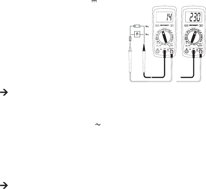
b) Voltage Measuring “V” .................................................................................................................................. 33
c) Direct Current Measuring “A DC” ................................................................................................................. 34
c) Direct Current Measuring “mA/µA DC” ........................................................................................................35
e) Resistance Measuring .................................................................................................................................. 36
f) Acoustic Continuity Test ............................................................................................................................... 36
g) Diode Test ....................................................................................................................................................37
h) Battery Test ...................................................................................................................................................37
9. ADDITIONAL FUNCTIONS ................................................................................................................................ 38
a) HOLD Function .............................................................................................................................................38
b) Display Lighting ............................................................................................................................................ 38
10. CLEANING AND MAINTENANCE ...................................................................................................................... 38
a) General .........................................................................................................................................................38
b) Cleaning ....................................................................................................................................................... 39
c) Inserting and Changing the Batteries ........................................................................................................... 39
d) Fuse Change ................................................................................................................................................ 40
11. DISPOSAL .......................................................................................................................................................... 41
12. TROUBLESHOOTING ........................................................................................................................................ 41
13. TECHNICAL DATA .............................................................................................................................................. 42


Dear customer,
Thank you for making the excellent decision to purchase this Voltcraft
®
product.
You have acquired a quality product from a brand family which has distinguished itself in the elds of measuring,
charging and grid technology thanks to its particular expertise and its continuous innovation.
With Voltcraft
®
, you will be able to handle difcult tasks, either as an ambitious hobbyist or as a professional user.
Voltcraft
®
offers reliable technology and a great price-performance-ratio.
We are positive: Starting to work with Voltcraft will also be the beginning of a long, successful relationship.
Enjoy your new Voltcraft
®
product!

International: www.conrad.com/contact
United Kingdom: www.conrad-electronic.co.uk/contact


Measuring and displaying electric parameters in the range of measurement category CAT III up to 600 V against
earth potential, pursuant to EN 61010-1 and all lower measuring categories. The meter must not be used in the
measuring category CAT IV.
- Measurement of direct and alternating voltage up to 600 V
- Measurement of direct currents up to 10 A
- Measurement of resistances up to 2000 kΩ
- Acoustic continuity test (<30 Ω)
- Diode test
- Battery test for 9 V-block and 1.5 V round cell batteries
The measurement functions are selected using the dial switch. The measuring range is selected manually for all
measuring functions.
The VC-125 shows averages in the AC voltage measuring range. Polarity is automatically indicated with the minus
prex (-) if the measured values are negative.
Use of personal protection equipment is recommended for measurements in CAT III environments. The meter must
not be used in the measuring category CAT IV.
The multimeter is operated with a conventional 9V block battery (type 6F22, NEDA1604 or same build). The device
must only be operated with the specied battery type. Rechargeable batteries should not be used because of the
lower capacity and the resulting shorter operating time.
The multimeter must not be operated when it is open, i.e. with an open battery compartment or when the battery
compartment cover is missing.
Measuring in potentially explosive areas (Ex) or damp rooms or under unfavourable ambient conditions is not
permitted. Unfavourable ambient conditions are: Moisture or high humidity, dust and ammable gases, fumes or
solvents, thunderstorms or thunderstorm conditions like strong electrostatic elds, etc.
For safety reasons, only use measuring lines or accessories which are adjusted to the specications of the multim-
eter when measuring.
The meter must only be operated by persons who are familiar with the required provisions for the measurement and
the possible dangers. Use of personal protection equipment is recommended.
Any use other than that described above will lead to damage to the product and involves additional risks such as, for
example, short circuit, re, electric shock, etc. No part of this product must be modied or converted!
Read the operating instructions carefully and keep them for later reference.
Always observe the safety information!


1 Display
2 HOLD button with latching function for holding the measuring display
3 Dial switch for selecting the measuring function
4 10 A-current measuring socket
5 COM measuring socket (reference potential, “minus potential”)
6 VΩmA measuring socket (“plus potential”)
7 Setup bracket, unfolding
8 Battery compartment
9 Button for display lighting

Digital multimeter VC-125
9V block battery
2 safety measuring lines with removable CAT III cover caps
Operating instructions







This device left the manufacturers factory in safe and perfect condition.
To maintain this condition and to ensure safe operation, the user must observe the safety information and warning
notes in these operating instructions.


An exclamation mark in a triangle shows important notes in these operating instructions that must be
strictly observed.
The triangle containing a lightning symbol warns against danger of electrical shock or impairment of the
electrical safety of the device.
The “arrow” symbol indicates that special advice and notes on operation are provided.
This device is CE-compliance and meets the applicable European directives.
Protection class 2 (double or reinforced insulation)
Attention, read instructions.
 Measuring category I for measurements at electrical and electronic devices that are not directly supplied
with mains voltage (e.g. battery-powered devices, protective low voltages, signal and control voltages,
etc.)
 Measuring category II for measurements at electrical and electronic devices connected to the mains
supply directly with a mains plug. This category also covers all lower categories (e.g. CAT I for measuring
signal and control voltages).
 Measuring category III for measuring in building installation (e.g. outlets or sub-distribution). This category
also covers all lower categories (e.g. CAT II for measuring electronic devices). Measuring operation in
CAT III is only permitted with measuring prods with a maximum free contact length of 4 mm or with cover
caps above the measuring prods.
 Measuring category IV for measurements at the source of the low-voltage installation (e.g. main distribu-
tion, building handover points of the energy suppliers, etc.), and outdoors (e.g. work at earthing cable,
outdoor line, etc.). This category also contains all lower categories. Measuring operation in CAT IV is only
permitted with measuring prods with a maximum free contact length of 4 mm or with cover caps above
the measuring prods.
Earth potential

For safety and approval reasons (CE), unauthorised conversion and/or modication of the device are not permitted.
Consult an expert when in doubt as to the operation, safety or the connection of the device.
Meters and accessories are not toys and have no place in the hands of children!
In commercial institutions, the accident prevention regulations of the Employers Liability Insurance Association for
Electrical Systems and Operating Materials are to be observed.
In schools, training centres, computer and self-help workshops, handling of meters must be supervised by trained
personnel in a responsible manner.
Ensure before every measurement that the meter is not set to another measuring range. Also observe that the
HOLD button was not pushed at the beginning of the measurement (display with the HOLD button pushed: “HOLD”).
If the HOLD button is pushed at commencement of measuring, no measured value is displayed!
When using the measuring lines without cover caps, measurements between the meter
and the earth potential must not be performed above the measuring category CAT II.
When measuring in the measuring category CAT III, the cover caps must be pushed
onto the measuring prods to avoid accidental short circuits during measurement.
Push the cover caps onto the measuring prods until they latch. To remove, pull the caps
fro the prods with a little force.
The measuring prods have to be removed from the measured object every time the
measuring range is changed.
The voltage between the connection points of the meter and earth potential must not exceed 600 V DC/AC in CAT
III.
Be especially careful when dealing with voltages higher than 33 V alternating (AC) or 70 V direct voltage (DC)! Even
at these voltages it is possible to receive a potentially fatal electric shock if you touch electrical conductors.
To avoid electric shock, make sure not to touch the connections/measuring points to be measured directly or
indirectly during measurement. Never reach beyond the noticeable grip area marks at the measuring prods during
measurements.
Check the meter and its measuring lines for damage before each measurement. Never carry out any measurements
if the protecting insulation is defective (torn, ripped off etc.). The enclosed measuring cables have a wear indicator.
When they are damaged, a second insulation layer in a different colour becomes visible. The measuring accessories
must no longer be used and must be replaced.
Do not use the multimeter just before, during or just after a thunderstorm (lightning! / high-energy overvoltage!).
Make sure that your hands, shoes, clothing, the oor, circuits and circuit components are dry.

Never operate the product in direct proximity of:
- strong magnetic or electromagnetic elds
- Transmitter aerials or HF generators.
This could affect the measurement.
If you have reason to believe that the device can no longer be operated safely, disconnect it immediately and make
sure it is not operated unintentionally. It can be assumed that safe operation is no longer possible if:
- the device shows visible damage
- the device no longer functions
- the device was stored under unfavourable conditions over an extended period of time or
- following considerable stress during transportation.
Do not switch the meter on immediately after it was taken from a cold to a warm environment. The condensation
that forms might destroy your device. Allow the device to reach room temperature before switching it on.
Do not leave the packaging material lying around carelessly since such materials can become dangerous toys in the
hands of children.
Also observe the safety information in each chapter of these instructions.

The multimeter (referred to as DMM in the following) indicates measured values on a digital display that can be
illuminated. The measured value display of the DMM comprises 2000 counts (count = smallest display value).
The meter can be used for do-it-yourself or for professional applications up to CAT III.
There are transport protection caps in the angled plugs of the enclosed measuring lines. Remove them before push-
ing the plugs into the meter sockets.
At the rear, there is an unfolding setup bracket (7) with which the DMM can be set up inclined. This makes it easier
to read the display.

The individual measuring functions and ranges are selected via a dial switch.
If the multimeter switch is set to “OFF”, the meter is switched off. Always turn the meter off when it is not in use.


The following symbols and information are present at the device or in the display.
OFF Switch position “off”
HOLD Call/deactivate data hold function Data-Hold function is active
OL Overow display, the measuring area was exceeded
Battery change symbol. When this symbol appears in the display, the battery must be replaced at
once to avoid measuring errors!
Symbol for the battery data used
Symbol for the diode test
Symbol for the acoustic continuity tester
AC Symbol for alternating current
DC Symbol for direct current
V, mV Volt (unit of electric voltage), Milli-Volt (exp.–3)
A, mA, µA Ampére (unit of electric current),
Milli-Ampére (exp.–3), Micro-Ampére (exp.–6)
Ω, kΩ Ohm (unit of electrical resistance), Kilo-Ohm (exp.3)
Button to switch the display lighting on and off
Symbol for the fuses used
BATT. Measuring function for battery test



















Always start your measurements with the largest measuring range. Then switch to the next-lower measuring
range on demand. Before a measuring range change, always remove the measuring prods from the measur-
ing object. Once shows “OL” (= overow), you have exceeded the measuring range.

The multimeter can be turned on and off using the dial switch. Turn the dial switch (3) to the corresponding meas-
urement function. To switch off, turn the dial switch to “OFF”. Always turn the meter off when it is not in use.




 
- Switch on the DMM and select the respective measuring range
“V DC”.
- Plug the red measuring line into the V measuring jack (6) and the
black measuring line into the COM measuring jack (5).
- Connect the two measuring prods to the object to be measured
(battery, circuit, etc.). The red measuring prod indicates the positive
pole, the black measuring prod the negative pole.
- The current measured value is indicated on the display.
- Remove the measuring lines from the object to be measured after
completion of the measurement and switch off the DMM.
If a minus “-” appears in front of the measured value for direct voltage, the measured voltage is negative (or
the measuring lines are swapped).
The voltage range “V DC” has an input resistance of >1 MOhm.


- Switch on the DMM and select the respective measuring range “V AC”.
-
Plug the red measuring line into the V measuring jack (6) and the black measuring line into the COM measuring
jack (5).
- Connect the two measuring prods to the object to be measured (battery, mains voltage, etc.).
- The current measured value is indicated on the display.
- Remove the measuring lines from the object to be measured after completion of the measurement and switch off
the DMM.
The voltage range V AC” has an input resistance of >1 MΩ.




Current measurement always takes place in series with the consumer. Before connecting the meter, the circuit must
be powered down. After the end of measuring, power down the circuit before removing the measuring lines. This
prevents the occurrence of light arcs.
Current measurements >5 A must only be performed for max. 30 seconds and with measuring breaks of 15 minutes.


- Switch on the DMM by the dial switch (3) and select the measuring
range ”10 A”.
-
Plug the red measuring line into the 10A measuring jack (4) and the
black measuring line into the COM measuring jack (5).
- Connect the two measuring prods in series with the
consumer. The red measuring prod indicates the pos- i-
tive pole, the black measuring prod the negative pole. Switch on
the measuring circuit.
- The measured value is indicated on the display.
When a minus “-” appears in front of the measured value when measuring direct current, the current has the
opposite direction (or the measuring lines have been swapped).
- Power down the measuring circuit after the end of measuring and remove the measuring prods from the measured
object. Switch off the device. Turn the dial switch to “OFF”.




Current measurement always takes place in series with the consumer. Before connecting the meter, the circuit must
be powered down. After the end of measuring, power down the circuit before removing the measuring lines. This
prevents the occurrence of light arcs.
The internal resistance of the meter causes a low voltage drop in the measuring circuit (max. 200 mV) because of
the integrated fuse in the mA measuring range. However, this is usually negligible.


- Switch on the DMM by the dial switch (3) and select the corresponding measuring range “mA/µA”.
-
Plug the red measuring line into the mA measuring jack (6) and the black measuring line into the COM measuring
jack (5).
- Connect the two measuring prods in series with the consumer. The red measuring prod indicates the positive pole,
the black measuring prod the negative pole. Switch on the measuring circuit.
- The measured value is indicated on the display.
When a minus “-” appears in front of the measured value when measuring direct current, the current has the
opposite direction (or the measuring lines have been swapped).
- Power down the measuring circuit after the end of measuring and remove the measuring prods from the measured
object. Switch off the device. Turn the dial switch to “OFF”.





- Switch on the DMM and select the respective measuring range
“Ω/kΩ”.
- Plug the red measuring line into the Ω measuring jack (6) and the
black measuring line into the COM measuring jack (5).
- Check the measuring lines for continuity by connecting the two
measuring prods. The impedance value must be approximately 0 -
1.5 Ohm (inherent impedance of the measuring lines).
- Now connect the two measuring prods to the object to be measured.
As long as the object to be measured is not high-impedance or
interrupted, the measured value will be indicated on the display.
Wait until the displayed value has stabilised. With impedances of
>1 MOhm, this may take a few seconds.
- Once “OL” (= overow) appears on the display, you have exceeded
the measuring range or the measuring circuit is interrupted.
- Remove the measuring lines from the object to be measured after
completion of the measurement and switch off the DMM.
If you carry out a resistance measurement, make sure that the measuring points you touch with the measur-
ing prods are free from dirt, oil, solderable lacquer or similar. Such circumstances can falsify the measured
result.



- Turn the DMM on and select measuring function
.
- Plug the red measuring line into the V measuring jack (6) and the black measuring line into the COM measuring
jack (5).
- A continuity value of less than approx. 30 Ohm is identied as continuity; in this case a beep sounds. The display
is not relevant in this test.
- Once “OL” (= overow) appears on the display, you have exceeded the measuring range or the measuring circuit
is interrupted.
- Remove the measuring lines from the object to be measured after completion of the measurement and switch off
the DMM.


Make sure that all circuit parts, circuits and components and other objects of measurement are discon-
nected from the voltage and discharged.
- Turn the DMM on and select measuring function
.
- Plug the red measuring line into the V measuring jack (6) and the
black measuring line into the COM measuring jack (5).
- Check the measuring lines for continuity by connecting the two
measuring prods. The value must be approximately 000. The DMM
emits a beet that is not relevant for the diode test.
- Connect the two measuring prods with the object to be measured
(diode).
- The display shows the continuity voltage “UF” in milli volt (mV).
When “OL” appears, the diode is measured in reverse direction
(UR) or the diode is faulty (interruption). Perform a counter-pole
measurement to check. At a continuity voltage of approx. <30 mV, a
beep sounds. However, this is not relevant.
- Remove the measuring lines from the object to be measured after
completion of the measurement and switch off the DMM.

The battery test permits review of the terminal voltage of 9 V block
batteries and 1.5 V round cell batteries. When testing, the battery is
charged with a low load current that leads to an indicative test result.
- Switch on the DMM and select the respective measuring range
“BATT.”.
- Plug the red measuring line into the V measuring jack (6) and the
black measuring line into the COM measuring jack (5).
- Connect the two measuring prods with the object to be measured
(battery).
- The display shows the terminal voltage of the battery under load
conditions in volt.
- Remove the measuring lines from the object to be measured after
completion of the measurement and switch off the DMM.



The HOLD function keeps the currently indicated measured value in the displays to allow you to read or record it
easily.





Push the button “HOLD” (2) to activate the hold function. The button latches and the display shows “HOLD”.
Push the button “HOLD” to deactivate the HOLD function. The display “HOLD” goes out.

With the DMM on, the lighting button with latching function (9) switches the display lighting on and off. Every push
will switch the lighting on or off. The lighting only remains on until the function is deactivated via the lighting button
(9) or the dial switch (position “OFF”).


To ensure accuracy of the multimeter over an extended period of time, it should be calibrated once a year.
Apart from occasional cleaning and battery and fuse replacements, the meter requires no servicing.
Notes on replacing the fuses and battery are provided below.




Always observe the following safety information before cleaning the device:




Do not use any abrasive cleaning agents or petrol, alcohol or the like to clean the product. They will damage the
surface of the meter. Furthermore, the fumes are hazardous to your health and explosive. Also do not use any
sharp-edged tools, screwdrivers, metal brushes, etc. for cleaning.
Use a clean, lint-free, antistatic, slightly damp cloth for cleaning the device or the display and the measuring lines.
Allow the product to dry completely before you use it again to conduct measurements.

Operation of the meter requires a 9 V block battery (e.g. 6F22 or same build). You need to insert a new, charged
battery before initial operation or when the battery change symbol appears on the display.

- Disconnect the connected measuring lines from the measuring
circuit and the meter. Switch off the DMM.
- Fold up the rear setup bracket and loosen the two rear screws at
the battery compartment lid (8) with a suitable Phillips screwdriver.
Remove the battery compartment lid from the device.
- Replace the at battery with a new one of the same type. Connect
the new battery with the battery clip in the correct polarity and insert
the battery into the compartment. Observe the polarity as indicated
in the battery compartment.
- Close the casing carefully again.











You can order suitable alkaline batteries stating the following item no.:
item no. 65 25 09 (please order one).
Only use alkaline batteries, as they are powerful and have a long service life.

The current measuring ranges are protected against overload with high-performance fuses. If no measurements in
the current measuring range are possible anymore, the fuses are probably defective and need to be replaced.




- Disconnect the connected measuring lines from the measuring circuit and the meter. Switch off the DMM.
- Loosen the four rear housing screws with a
matching Phillips screwdriver. Carefully loosen the
two housing halves from each other and turn away
the rear as shown. Observe the battery cable
- Replace the defective fuse with a new fuse of the
same type and rated current.
FUSE1: FF200 mA 600 V 5 mm x 20 mm
FUSE2: F10A 600 V 6,3 mm x 25.4 mm
However, always observe the information at the
device or the values of the fuse used.
- Close the casing carefully again.



Old electronic devices are recyclable and should not be disposed of in household waste. At the end of its
service life, dispose of the product at the community collection point according to the relevant statutory
regulations. It is prohibited to dispose of the device in household waste.

You as the end user are required by law (Battery Ordinance) to return all used batteries/rechargeable batteries.
Disposing of them in household waste is prohibited!
Batteries/rechargeable batteries containing harmful substances are marked with the following symbols,
which point out that they are not allowed to be disposed of in the domestic refuse. The descriptions for
the respective heavy metals are: Cd = cadmium, Hg = mercury, Pub = lead. You may return used batter-
ies/rechargeable batteries free of charge at the ofcial collection points of your community, in our stores,
or wherever batteries/rechargeable batteries are sold!
You thus full the legal requirements and make your contribution to protecting the environment!






  
The multimeter does not work. Are the batteries dead? Check the status. Replace the battery.
No measured value change
Is the wrong measuring function
activated (AC/DC)?
Check the measuring range (AC/DC)
and switch the function if required.
Are the measuring lines reliably
inserted in the measuring jacks?
Check the proper t of the measuring
lines
Is the Hold function activated
(display "HOLD")?
Push the button "HOLD" to deactivate
this function.
Fuse in the current measuring range
defective
Check the corresponding fuse.




Display ..................................................2000 counts (characters)
Measuring rate ......................................approx. 2 measuring operations/second
Measuring method V/AC ......................arithmetic average
Measuring line length ...........................each approx. 90 cm
Measuring impedance .........................>1 MΩ (V-range)
Measuring socket distance ..................19 mm
Voltage supply .....................................9 V block batteries (NEDA 1604, 6F22 or same build)
Operating conditions ............................0 to 50 °C (<70%rF)
Operating height ..................................max. 2000 m
Storage conditions ...............................-20 °C to +60 °C (<80%rF)
Weight .................................................approx. 210 g
Dimensions (LxWxH) ............................138 x 68 x 37 (mm)
Measuring category ..............................CAT III 600 V
Degree of contamination ......................2

Statement of accuracy in ± (% of reading + display error in counts (= number of smallest points)). The accuracy is
valid for one year at a temperature of +23°C ± 5°C, and at a relative humidity of less than 75%, non-condensing.

  
200.0 mV
±(0.7% + 3)
0.1 mV
2000 mV 1 mV
20.00 V 0.01 V
200.0 V
±(1.0% + 3)
0.1 V
600 V 1 V
Overload protection 600 V; Impedance: >1 MΩ


  
200 V
±(1.5% + 12)
0.1 V
600 V 1 V
Frequency range 45 – 450 Hz; Overload protection 600 V; Impedance: >1 MΩ

  
2000 µA
±(1.5% + 3)
1 µA
20 mA 0.01 mA
200 mA 0.1 mA
10 A ±(2.5% + 2) 0.01 A
Overload protection 600 V; high-performance ceramic fuses:

  
200.0 Ω
±(1.2% + 4)
0.1 Ω
2000 Ω 1 Ω
20.00 kΩ 0.01 kΩ
200.0 kΩ 0.1 kΩ
2000 kΩ ±(1.5% + 2) 1 kΩ
Overload protection 250 V; max. 15 s.

  
1.5 V
±(1.5% + 3)
0.001 V
9 V 0.01 V
Load current:
1.5 V-range: 100 mA
9 V-range: 6 mA


 
approx. 2.8 V 1 mV
Overload protection: 250 V max. 15 s; test current max. 1 mA

Overload protection: 250 V max. 15 s; <30 Ω permanent sound




F

1. INTRODUCTION ............................................................................................................................................... 46
2. UTILISATION CONFORME ............................................................................................................................... 47
3. ÉLÉMENTS DE COMMANDE ........................................................................................................................... 48
4. ÉTENDUE DE LA LIVRAISON .......................................................................................................................... 48
5. CONSIGNES DE SÉCURITÉ ............................................................................................................................ 48
6. DESCRIPTION DU PRODUIT ........................................................................................................................... 51
7. INFORMATIONS ET SYMBOLES SUR L’ÉCRAN ............................................................................................ 52
8. MODE DE MESURE .......................................................................................................................................... 53
a) Mise en marche du multimètre .................................................................................................................... 53
b) Mesure de la tension « V » ..........................................................................................................................54
c) Mesure du courant continu « A DC » ........................................................................................................... 55
d) Mesure du courant continu « mA/µA DC » ..................................................................................................56
e) Mesure de la résistance .............................................................................................................................. 57
f) Test de continuité acoustique ...................................................................................................................... 57
g) Test des diodes ............................................................................................................................................ 58
h) Test des piles ............................................................................................................................................... 58
9. FONCTIONS SUPPLÉMENTAIRES .................................................................................................................. 59
a) Fonction HOLD ............................................................................................................................................59
b) Éclairage de l’écran ..................................................................................................................................... 59
10. NETTOYAGE ET ENTRETIEN .......................................................................................................................... 59
a) Généralités .................................................................................................................................................. 59
b) Nettoyage .................................................................................................................................................... 60
c) Mise en place et remplacement de la batterie .............................................................................................60
d) Remplacement des fusibles ........................................................................................................................ 61
11. ÉLIMINATION ....................................................................................................................................................62
12. DÉPANNAGE .................................................................................................................................................... 62
13. CARACTÉRISTIQUES TECHNIQUES .............................................................................................................. 63


Cher client,
Vous avez pris une très bonne décision en achetant ce produit Voltcraft
®
et nous désirons vous en remercier.
Vous avez acquis un produit de qualité d’une gamme de marques qui se distingue par une grande compétence et
des innovations permanentes dans le domaine des techniques de mesure, de charge et de réseau.
Voltcraft
®
vous permet de réaliser les tâches les plus exigeantes, que vous soyez bricoleur ambitieux ou utilisateur
professionnel. Voltcraft
®
vous propose une technologie able avec un rapport qualité-prix avantageux.
Nous en sommes convaincus : votre premier contact avec Voltcraft marque le début d’une coopération efcace et
durable.
Nous vous souhaitons beaucoup de plaisir avec votre nouveau produit Voltcraft
®
!

France (email): technique@conrad-france.fr
Suisse: www.conrad.ch
www.biz-conrad.ch


- Mesure et afchage des grandeurs électriques dans la plage de la catégorie de surtension CAT III jusqu’à max.
600 V par rapport au potentiel terrestre conformément à la norme EN 61010-1 ainsi que de toutes les catégories
de mesure inférieures. Il est interdit d’employer l’instrument de mesure dans la catégorie de mesure CAT IV.
- Mesure des tensions continues et alternatives jusqu’à max. 600 V
- Mesure des courants continus jusqu’à max. 10 A
- Mesure des résistances jusqu’à 2 000 kΩ
- Test de continuité acoustique (<30 Ω)
- Test des diodes
- Test des piles 9 V et des piles rondes 1,5 V
Les fonctions de mesure se sélectionnent à l’aide du bouton rotatif. Avec toutes les fonctions de mesure, la sélec-
tion de la plage de mesure est automatique.
Avec le multimètre VC-125, des valeurs moyennes sont afchées dans la plage de mesure de tension CA. Avec les
mesures négatives, la polarité est automatiquement indiquée par un signe moins (-).
Pour les mesures dans les environnements de CAT III, il est recommandé d’utiliser un équipement de protection
individuelle. Il est interdit d’employer l’instrument de mesure dans la catégorie de mesure CAT IV.
Le multimètre fonctionne avec une pile carrée 9 V disponible dans le commerce (type 6F22, NEDA1604 ou simi-
laire). L’appareil doit uniquement être utilisé avec le type de piles stipulé. Compte tenu de leur capacité inférieure et
de l’autonomie inférieure qui en résulte, il est déconseillé d’employer des batteries.
Il est interdit d’utiliser le multimètre lorsque son boîtier est ouvert, lorsque le logement de la pile est ouvert ou que le
couvercle du logement de la pile a été retiré.
Il est interdit d’effectuer des mesures dans les atmosphères explosives (Ex) et locaux humides ainsi qu’en présence
de conditions ambiantes défavorables. Des conditions d’environnement défavorables sont : présence d’eau ou d’hu-
midité atmosphérique élevée, poussière et gaz inammables, vapeurs ou solvants, orages ou conditions orageuses
telles que les champs électrostatiques de forte intensité, etc.
Pour effectuer les mesures, utilisez uniquement des lignes de mesure ou des accessoires de mesure conformes
aux spécications du multimètre.
L’utilisation de l’instrument de mesure est strictement réservée aux personnes familiarisées avec les consignes
inhérentes à la mesure et les dangers potentiels. L’utilisation de l’équipement de protection individuelle est recom-
mandée.
Toute utilisation autre que celle décrite précédemment peut endommager le produit. De plus, cela s’accompagne de
dangers tels que courts-circuits, incendies, électrocutions, etc. Il est interdit de transformer ou modier le produit !
Lisez attentivement le mode d’emploi et conservez-le an de pouvoir le consulter ultérieurement.
Observez impérativement les consignes de sécurité !


1 Écran
2 Touche HOLD avec fonction d’enclenchement pour l’immobilisation de l’afchage de la valeur mesurée
3 Bouton rotatif pour la sélection des fonctions de mesure
4 Prise de mesure du courant 10 A
5 Prise de mesure COM (potentiel de référence, « potentiel négatif »)
6 Prise de mesure VΩmA (« potentiel positif »)
7 Pied support escamotable
8 Logement de la pile
9 Touche pour l’éclairage de l’écran

Multimètre numérique VC-125
Pile carrée 9 V
2 lignes de mesure de sécurité avec capuchons CAT III amovibles
Mode d’emploi









Du point de vue de la sécurité technique, cet appareil a quitté l’usine dans un état irréprochable.
An de maintenir le produit dans cet état et de garantir un fonctionnement en toute sécurité, l’utilisateur est tenu
d’observer les consignes de sécurité et avertissements dans le présent mode d’emploi.


Dans le présent mode d’emploi, un point d’exclamation placé dans un triangle signale les informations
importantes à impérativement respecter.
Le symbole de l’éclair dans le triangle met en garde contre un danger d’électrocution ou une atteinte à la
sécurité électrique de l’appareil.
La « èche » précède les recommandations et consignes d’utilisation particulières.
Cet appareil satisfait aux exigences CE et aux directives nationales et européennes applicables
Classe de protection 2 (double isolation ou isolation renforcée).
Attention, lire le mode d’emploi.
 Catégorie de mesure I pour les mesures sur les appareils électriques et électroniques qui ne sont pas di-
rectement alimentés par la tension du secteur (par ex. appareils à fonctionnement sur pile, basse tension
de protection, tensions des signaux et tensions pilotes, etc.)
 Catégorie de mesure II pour les mesures sur les appareils électriques et électroniques directement
alimentés en tension du secteur par le biais d’une che de secteur. Cette catégorie comprend également
toutes les catégories inférieures (par ex. CAT I pour la mesure des tensions des signaux et tensions
pilotes).
 Catégorie de mesure III pour les mesures réalisées à l’intérieur des bâtiments (par ex. prises de courant
ou distributions secondaires). Cette catégorie comprend également toutes les catégories inférieures
(par ex. CAT II pour les mesures réalisées sur les appareils électriques). Dans la CAT III, le mode de
mesure est uniquement autorisé avec des pointes de mesure dont la longueur libre des contacts est
inférieure ou égale à 4 mm ou avec des capuchons sur les pointes de mesure.
 Catégorie de mesure IV pour les mesures réalisées à la source de l’installation basse tension (par ex.
distribution principale, points de jonction domestique des fournisseurs d’énergie, etc.) et en plein air
(par ex. travaux sur les câbles souterrains, lignes électriques aériennes, etc.). Cette catégorie comprend
également toutes les catégories inférieures. Dans la CAT IV, le mode de mesure est uniquement autorisé
avec des pointes de mesure dont la longueur libre des contacts est inférieure ou égale à 4 mm ou avec
des capuchons sur les pointes de mesure.
Potentiel terrestre

Pour des raisons de sécurité et d’homologation (CE), toute transformation ou modication arbitraire de l’appareil est
interdite.
Si vous avez des doutes à propos du principe de fonctionnement, de la sécurité ou du raccordement de l’appareil,
adressez-vous à un technicien spécialisé.
Les instruments de mesure de mesure et les accessoires ne sont pas des jouets, conservez-les donc hors de
portée des enfants !
Dans les installations industrielles, il convient d’observer les consignes de prévention des accidents relatives aux
installations et moyens d’exploitation électriques, édictées par les associations professionnelles.
Dans les écoles, les centres de formation, les ateliers de loisirs et de réinsertion, la manipulation d’instruments de
mesure doit être surveillée par des personnes spécialement formées à cet effet.
Avant chaque mesure, assurez-vous que l’instrument de mesure ne se trouve pas dans une autre plage de mesure.
Assurez-vous également que la touche HOLD n’est pas enfoncée au début de la mesure (indication « HOLD »
sur l’écran lorsque la touche HOLD est enfoncée). Lorsque la touche HOLD est enfoncée au début de la mesure,
aucune valeur mesurée ne s’afche !
En cas d’utilisation de lignes de mesure sans capuchons, il est interdit de réaliser des
mesures entre l’instrument de mesure et le potentiel terrestre au-delà de la catégorie de
mesure CAT II.
Pour les mesures dans la catégorie de mesure CAT III, les capuchons doivent être
emboîtés sur les pointes de mesure an d’éviter les courts-circuits accidentels durant la
mesure.
Emboîtez les capuchons sur les pointes de mesure jusqu’à ce qu’ils s’enclenchent. Tirer
vigoureusement pour retirer les capuchons des pointes.
Avant chaque changement de plage de mesure, éloignez les pointes de mesure du composant à mesurer.
Dans la catégorie CAT III, la tension entre les points de raccordement de l’instrument de mesure et le potentiel
terrestre ne doit pas être supérieure à 600 V CC/CA.
Une prudence toute particulière s’impose durant la manipulation de tensions alternatives supérieures à 33 V (CA)
ou de tensions continues supérieures à 70 V (CC) ! Ces tensions sont déjà sufsantes pour provoquer un danger
d’électrocution mortelle en cas de contact avec les conducteurs électriques.
An d’éviter une électrocution, veillez à ne pas toucher directement ou indirectement les raccords et points de
mesure durant la mesure. Pendant la mesure, il est interdit de tenir les pointes de mesure en dehors des zones de
préhension prévues à cet effet.
Avant chaque mesure, assurez-vous que votre instrument de mesure et les lignes de mesure ne sont pas endom-
magés. Ne réalisez jamais des mesures lorsque l’isolation est endommagée (ssurée, déchirée, etc.). Les câbles
de mesure fournis comportent un indicateur d’usure. En cas de détérioration, une deuxième couche isolante d’une
autre couleur devient visible. Les accessoires de mesure ne doivent alors plus être employés et doivent être rempla-
cés.
N’employez pas le multimètre juste avant, pendant ou juste après un orage (coup de foudre ! / surtensions à haute
énergie !). Veillez impérativement à ce que vos mains, vos chaussures, vos vêtements, le sol, les circuits et les
éléments du circuit, etc. soient parfaitement secs.

Évitez toute exploitation à proximité immédiate de :
- champs électromagnétiques ou magnétiques à forte intensité
- antennes de transmission ou générateurs H.F.
La valeur mesurée risquerait alors d’être faussée.
Lorsqu’un fonctionnement sans danger de l’appareil n’est plus garanti, il convient de mettre celui-ci hors service et
d’empêcher toute remise en marche accidentelle. Une utilisation sans danger n’est plus garantie lorsque :
- l’appareil est visiblement endommagé,
- l’appareil ne fonctionne plus et
- en cas de stockage prolongé dans des conditions défavorables ou
- suite à de sévères contraintes liées au transport.
N’allumez jamais l’instrument de mesure immédiatement après l’avoir transporté d’un local froid dans un local
chaud. L’eau de condensation qui se forme alors risquerait de détruire l’appareil. Attendez que l’appareil ait atteint la
température ambiante avant de le brancher.
Ne laissez pas le matériel d’emballage sans surveillance ; il pourrait constituer un jouet dangereux pour les enfants.
Observez également les consignes de sécurité gurant dans les différents chapitres.

Les valeurs mesurées s’afchent sur le multimètre (appelé DMM par la suite) sur un écran numérique à éclai-
rage. L’afchage des valeurs mesurées du DMM comprend 2 000 counts (count = plus petite valeur pouvant être
afchée).
L’instrument de mesure a aussi bien été conçu pour une utilisation dans le cadre des loisirs que pour une utilisation
professionnelle jusqu’à la CAT III.
Les connecteurs coudés des lignes de mesure fournies contiennent des capuchons de transport. Retirez-les avant
d’insérer les connecteurs dans les prises de l’instrument de mesure.
Un pied support escamotable (7) qui permet d’incliner le DMM est disponible au dos. Cela facilite la lecture sur
l’écran.

Un bouton rotatif permet de sélectionner les différentes fonctions et plages de mesure.
Lorsque le bouton se trouve en position « OFF », le multimètre est éteint. Éteignez toujours l’instrument de mesure
lorsque vous ne l’utilisez pas.


Les symboles et informations ci-dessous sont apposés sur l’appareil ou s’afchent sur l’écran.
OFF Position « OFF » de l’interrupteur
HOLD Activer / désactiver la fonction Data Hold. La fonction Data Hold est activée
OL Indication d’un dépassement ; la plage de mesure a été dépassée
Symbole de remplacement des piles. Lorsque ce symbole s’afche sur l’écran, la batterie doit être
remplacée dans les plus brefs délais an d’éviter toute erreur de mesure !
Symbole pour les caractéristiques des piles employées
Symbole pour le test des diodes
Symbole pour le contrôleur acoustique de continuité
AC Symbole pour courant alternatif
DC Symbole pour courant continu
V, mV Volt (unité de la tension électrique), millivolt (exp.-3)
A, mA, µA Ampère (unité de l’intensité électrique du courant),
milliampère (exp.-3), microampère (exp.-6)
Ω, kΩ Ohm (unité de la résistance électrique), kiloohm (exp.3)
Touche permettant d’allumer et éteindre l’éclairage de l’écran
Symbole pour les fusibles employés
BATT. Fonction de mesure pour le test des piles






















Commencez toujours les mesures avec la plus grande plage de mesure. Le cas échéant, passez ensuite à
la plage de mesure inférieure suivante. Avant chaque changement de la plage de mesure, toujours retirer
les pointes de mesure du composant à mesurer. Dès que « OL » (= débordement) s’afche, cela signie que
vous avez dépassez la plage de mesure.

Le multimètre s’allume et s’éteint à l’aide du bouton rotatif. Tournez le bouton rotatif (3) dans la position de la
mesure correspondante. Pour l’éteindre, tournez le bouton rotatif en position « OFF ». Éteignez toujours l’instrument
de mesure lorsque vous ne l’utilisez pas.




 
- Allumez le DMM puis sélectionnez la plage de mesure
correspondante « V DC ».
- Enchez la ligne de mesure rouge dans la prise de mesure V (6) et
la ligne noire dans la prise de mesure COM (5).
- Reliez les deux pointes de mesure au composant à mesurer (pile,
circuit, etc.). La pointe de mesure rouge correspond à la borne plus,
la pointe de mesure noire à la borne négative.
- La valeur mesurée actuelle s’afche sur l’écran.
- Après la mesure, retirez les pointes de mesure du composant à
mesurer puis éteignez le DMM.
Dès qu’un signe moins « - » précède la tension continue mesurée, cela signie que la tension mesurée est
négative (ou que les lignes de mesure ont été permutées).
La plage de tension « V DC » présente une résistance d’entrée > 1 MΩ.


- Allumez le DMM puis sélectionnez la plage de mesure correspondante « V AC ».
-
Enchez la ligne de mesure rouge dans la prise de mesure V (6) et la ligne noire dans la prise de mesure COM (5).
- Reliez les deux pointes de mesure au composant à mesurer (générateur, tension du secteur, etc.).
- La valeur mesurée actuelle s’afche sur l’écran.
- Après la mesure, retirez les pointes de mesure du composant à mesurer puis éteignez le DMM.
La plage de tension « V AC » comporte une résistance d’entrée > 1 MΩ.
13

Hulp nodig? Stel uw vraag in het forum

Spelregels

Misbruik melden

Gebruikershandleiding.com neemt misbruik van zijn services uitermate serieus. U kunt hieronder aangeven waarom deze vraag ongepast is. Wij controleren de vraag en zonodig wordt deze verwijderd.

Product:

Bijvoorbeeld antisemitische inhoud, racistische inhoud, of materiaal dat gewelddadige fysieke handelingen tot gevolg kan hebben.

Bijvoorbeeld een creditcardnummer, een persoonlijk identificatienummer, of een geheim adres. E-mailadressen en volledige namen worden niet als privégegevens beschouwd.

Spelregels forum

Om tot zinvolle vragen te komen hanteren wij de volgende spelregels:

Belangrijk! Als er een antwoord wordt gegeven op uw vraag, dan is het voor de gever van het antwoord nuttig om te weten als u er wel (of niet) mee geholpen bent! Wij vragen u dus ook te reageren op een antwoord.

Belangrijk! Antwoorden worden ook per e-mail naar abonnees gestuurd. Laat uw emailadres achter op deze site, zodat u op de hoogte blijft. U krijgt dan ook andere vragen en antwoorden te zien.

Abonneren

Abonneer u voor het ontvangen van emails voor uw Voltcraft VC-125 bij:


U ontvangt een email met instructies om u voor één of beide opties in te schrijven.


Ontvang uw handleiding per email

Vul uw emailadres in en ontvang de handleiding van Voltcraft VC-125 in de taal/talen: Nederlands, Duits, Engels, Frans als bijlage per email.

De handleiding is 1,72 mb groot.


U ontvangt de handleiding per email binnen enkele minuten. Als u geen email heeft ontvangen, dan heeft u waarschijnlijk een verkeerd emailadres ingevuld of is uw mailbox te vol. Daarnaast kan het zijn dat uw internetprovider een maximum heeft aan de grootte per email. Omdat hier een handleiding wordt meegestuurd, kan het voorkomen dat de email groter is dan toegestaan bij uw provider.

Stel vragen via chat aan uw handleiding

Stel uw vraag over deze PDF

Uw handleiding is per email verstuurd. Controleer uw email

Als u niet binnen een kwartier uw email met handleiding ontvangen heeft, kan het zijn dat u een verkeerd emailadres heeft ingevuld of dat uw emailprovider een maximum grootte per email heeft ingesteld die kleiner is dan de grootte van de handleiding.

Er is een email naar u verstuurd om uw inschrijving definitief te maken.

Controleer uw email en volg de aanwijzingen op om uw inschrijving definitief te maken

U heeft geen emailadres opgegeven

Als u de handleiding per email wilt ontvangen, vul dan een geldig emailadres in.

Uw vraag is op deze pagina toegevoegd

Wilt u een email ontvangen bij een antwoord en/of nieuwe vragen? Vul dan hier uw emailadres in.


Info