Power outlets......................................58
9 Warning
Never adjust seats while driving, as they
could move uncontrollably.
Important: Do not sit nearer than
10inches (25 cm) from the steering
wheel, to permit safe airbag deployment.
Seats, interior31
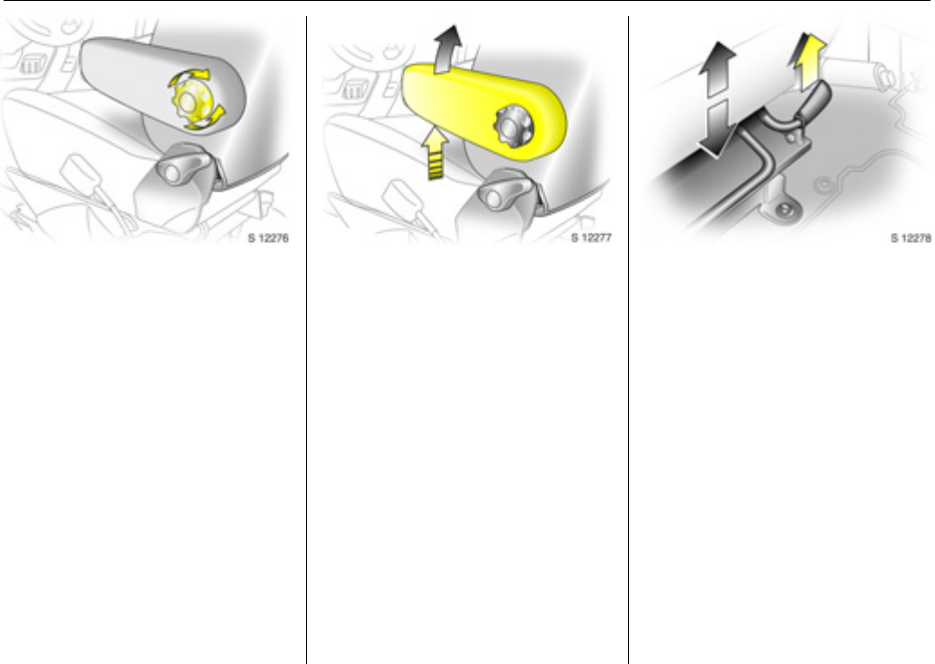
Adjusting the lumbar support 3
To adjust, turn the handwheel whilst
relieving the load on the backrest.
Adjust lumbar support to suit personal
requirements.
Adjusting armrest support 3:
Adjust armrest support to suit personal
re qu ir eme n ts.
zRaise armrest in increments to desired
height.
zTo reposition, fully raise armrest before
lowering.
Adjusting seat height 3
To adjust, pull lever at side of seat.
Pull lever and remove body weight from
seat to raise it or press down on seat with
body weight to lower it.
Seats, interior32
Seat position
Adjust driver’s seat such that with the
driver sitting upright the steering wheel is
held in the area of its upper spokes with the
driver’s arms slightly bent.
The seat backrests must not be tilted too
far back (recommended maximum tilting
angle approx. 25°).
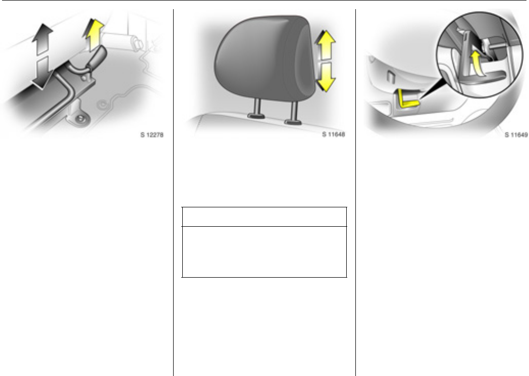
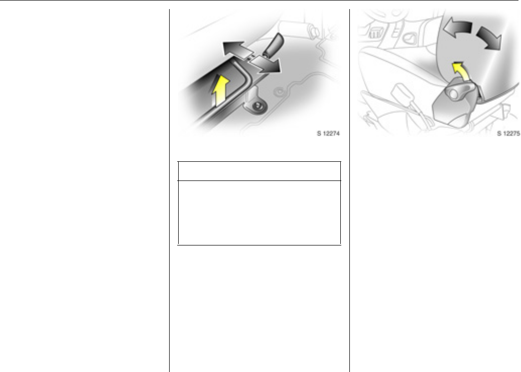
Head restraints
Adjusting head restraint height, hold firmly
and adjust height, then release.
Do not attach objects or components that
are not approved for the Vivaro, to the
head restraints. These affect the protective
effect of the head restraints and can be
propelled through the vehicle in an
uncontrolled manner if the driver brakes
hard or an accident occurs.
Head restraint position
The centre of the head restraint should be
at eye level.
Adjust to highest position if this is not
possible for extremely tall people, and
adjust to lowest position for extremely
small people.
9 Warning
Disreg ard can lead to injurie s which could
be fatal. Vehicle passengers must be
informed accordingly.
9 Warning
Disregard ca n lead to injuries which c ould
be fatal. Vehicle passengers must be
informed accordingly.
Seats, interior33
Head restraint removal
To remove the head restraints, pull lock tab
and pull the restraint upwards.
Stow head restraints securely in load
compartment. Do not drive with head
restraints removed if the seat is occupied.
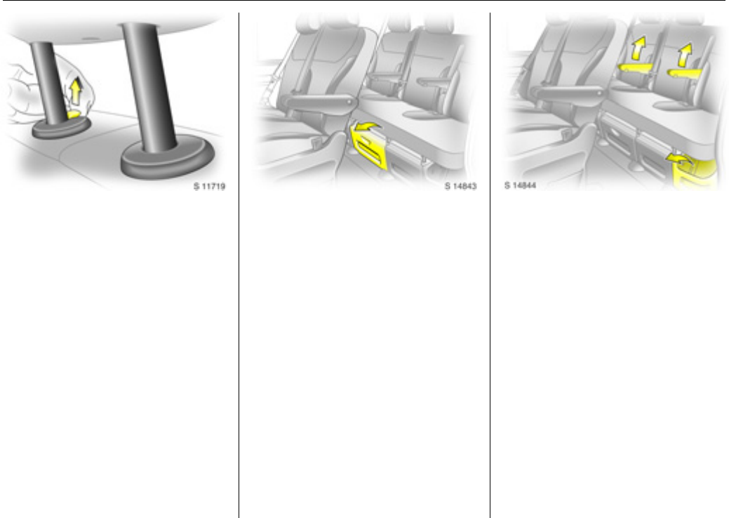
Rear seats 3
On some model variants, the rear
passenger compartment offers storage in
the seat trims.
To enable long items to be stored under
the seats, the centre rear seat trim cover 3
can be unclipped.
The load cap acity can be increased furthe r
by folding or removing the rear seats 3.
When folding or removing the rear seat
ensure the armrests 3 are folded away in
their most upright position. Also remove
the lower seat trim side pockets 3
disconnecting them from the locating clips.
Seats, interior34
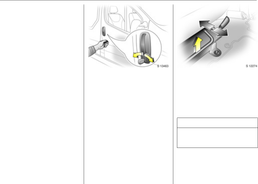
Rear seat access 3
To facilitate access to the rear seats, fold
the seat backrest forwards. If necessary
release the two-latch seat belt from its
buckles.
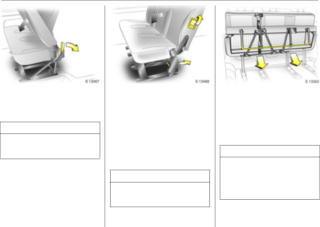
Folding seats 3
On some model variants, the load area can
be increased by folding up the rear seats.
Remove the head restraints. Pull the side
handle to release the backrest and fold
forwards onto the seat cushion, if
necessary releasing the two-latch seat
belts from their buckles.
Release both locking bars at the rear base
of the seat by pulling backwards.
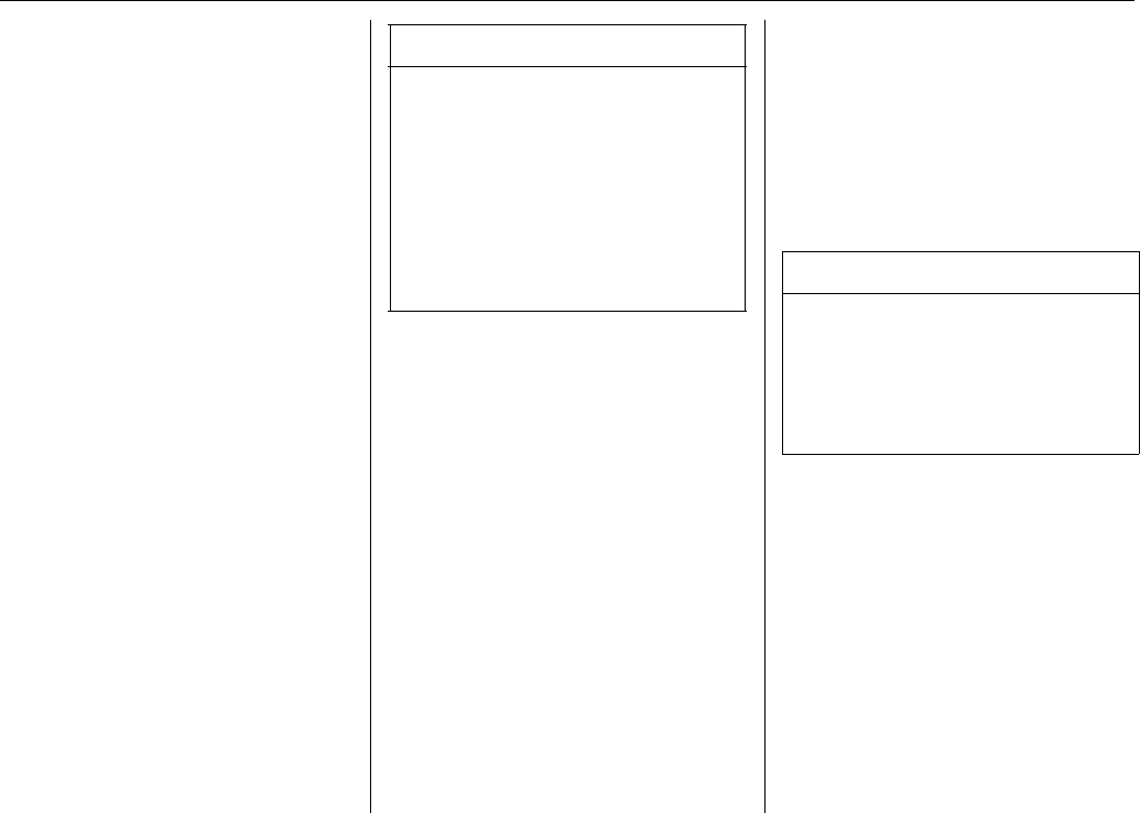
Lift and fold the seat assembly, until the
seat frame rests in place.
To return the folding seat to the upright
position, support the seat assembly and
release the bar by pulling the bar directly
towards you. Gradually lower the seat
assembly, allowing the rear support legs to
fold down. Lower the seat completely,
ensuring the rear support legs are located,
and latched. Raise the backrest, reinstall
head restraints and connect the seat belts.
9 Warning
Ensure that the backrest returns to its
correct position and the seat belt buckles
engage securely - see page 39, 40.
9 Warning
When folding the seat use caution -
beware of moving parts. Ensure the seat
is secure when completely folded.
9 Warning
When installing the seat, ensure that the
seat is properly located on the anchor
points and that the locking catches are
fully engaged, the backrest is returned to
the correct position and the seat belts are
engaged securely.
Seats, interior35
Removable rear seats 3
On some model variants, the load area can
be increased by removing the rear seats.
Release the seats by pressing down and
sliding forward the locking catch located
on the left and right-hand seat mountings.
With both catches raised, push the seat
unit towards the rear and release them
from the floor anchor points. The seat can
then be lifted out.
The seats must be removed through the
sliding door only.
9 Warning
Removable seats are heavy! Do not
attempt to remove without assistance.
When installing the seats, ensure that the
seats are properly located on the anchor
points and that the locking catches are
fully engaged.
9 Warning
When re-installing seats always ensure
that the row with the folding access
seatB is positioned correctly in front of
the fixed seat rowA.
If the seats are incorrectly positioned,
access for passengers is seriously
impeded. Disregard of these instructions
may endanger life.
Seats, interior36
Three-stage restraint system
The system comprises
zThree-point seat belts.
zBelt tensioners on the front seats.
zAirbag systems for driver, front
passenger 3 and outboard rear seat
occ upants 3.
The three stages are activated in sequence
depending on the seriousness of the
accident:
zThe automatic seat belt locking devices
prevent the belt strap from being pulled
out and thus ensure that the vehicle
occupants are retained in their seats.
zThe front seat belt buckles are pulled
downwards. As a result, the seat belts
are instantaneously tightened and the
occupants are made aware of the
deceleration of the vehicle at a very early
stage. This reduces stress placed on the
body.
zThe airbag system is additionally
triggered in the event of a serious
accident involving a frontal impact and
forms a sa fety cushion for the driver and
front passenger 3. The side airbag
system3 protects the occupants in the
front of the vehicle in the event of side-on
collisions.
Three-point seat belts
The vehicle is equipped with three-point
seat belts with automatic retractors and
locking devices, allowing freedom of body
movement although the spring tensioned
belts are always a snug fit.
The belt has a “vehicle sensitive retractor”
which is designed to lock during heavy
acceleration or deceleration in any
direction.
In the event of an accident, people not
wearing seat belts endanger their fellow
occupants and themselves.
Seat belts are designed to be used by only
one person at a time. They are only
suitable for children aged up to 12 or
smaller than 150cm if used in conjunction
with a child restraint.
9 Warning
The airbag system serves to supplement
the three-point seat belts and belt
tensioners. The seat b elts must therefore
always be worn. Disregard of these notes
can lead to injuries which may be fatal.
Vehicle passengers must be informed
accordingly.
Be sure to read the detailed descriptions
of all the restraint systems on the
following pages!
9 Warning
Always wear your seat belt - and that
means also in urban traffic and when you
are a rear seat passenger. It can save
your life!
Pregnant women too must always wear a
seat belt.
Seats, interior37
Inspection of belts
Check all parts of the belt system
periodically for damage and function.
Replace damaged components. After an
accident, have the belts and triggered belt
tensioners replaced by a workshop.
Do not perform any alterations on the
belts, their anchorages, the automatic
retractors or the belt buckles.
Make sure that belts are not damaged or
trapped by sharp-edged objects.
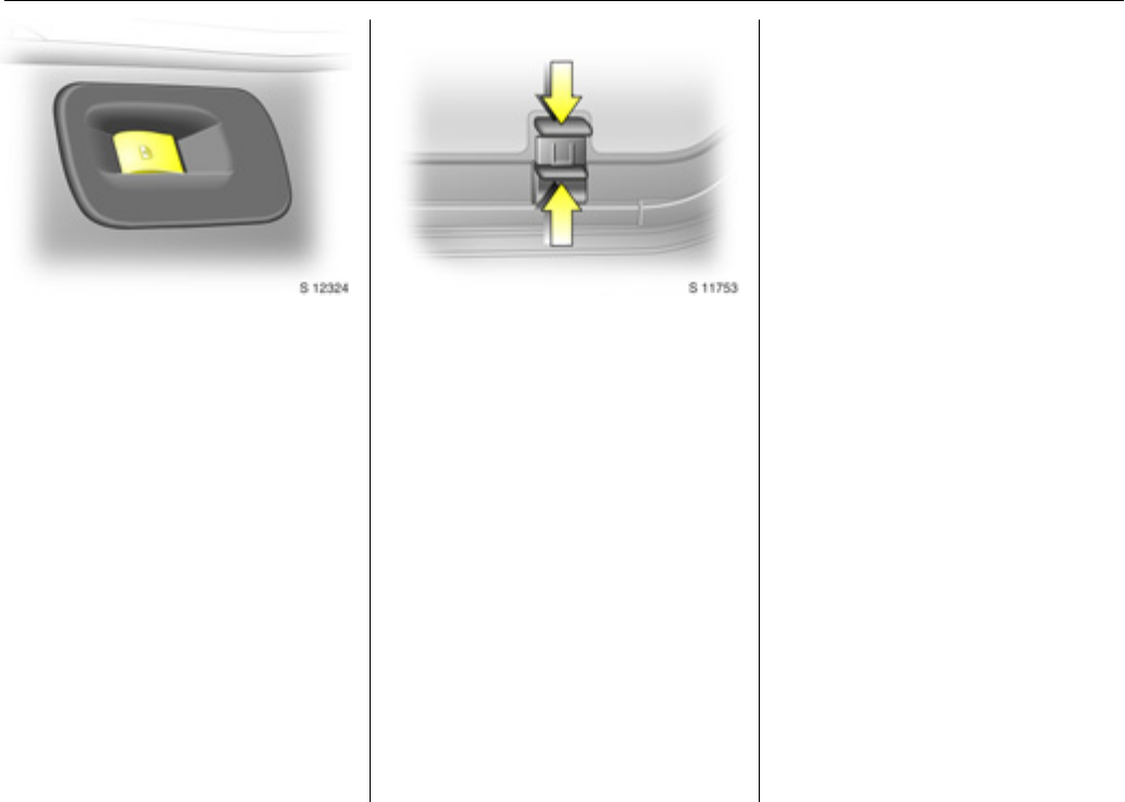
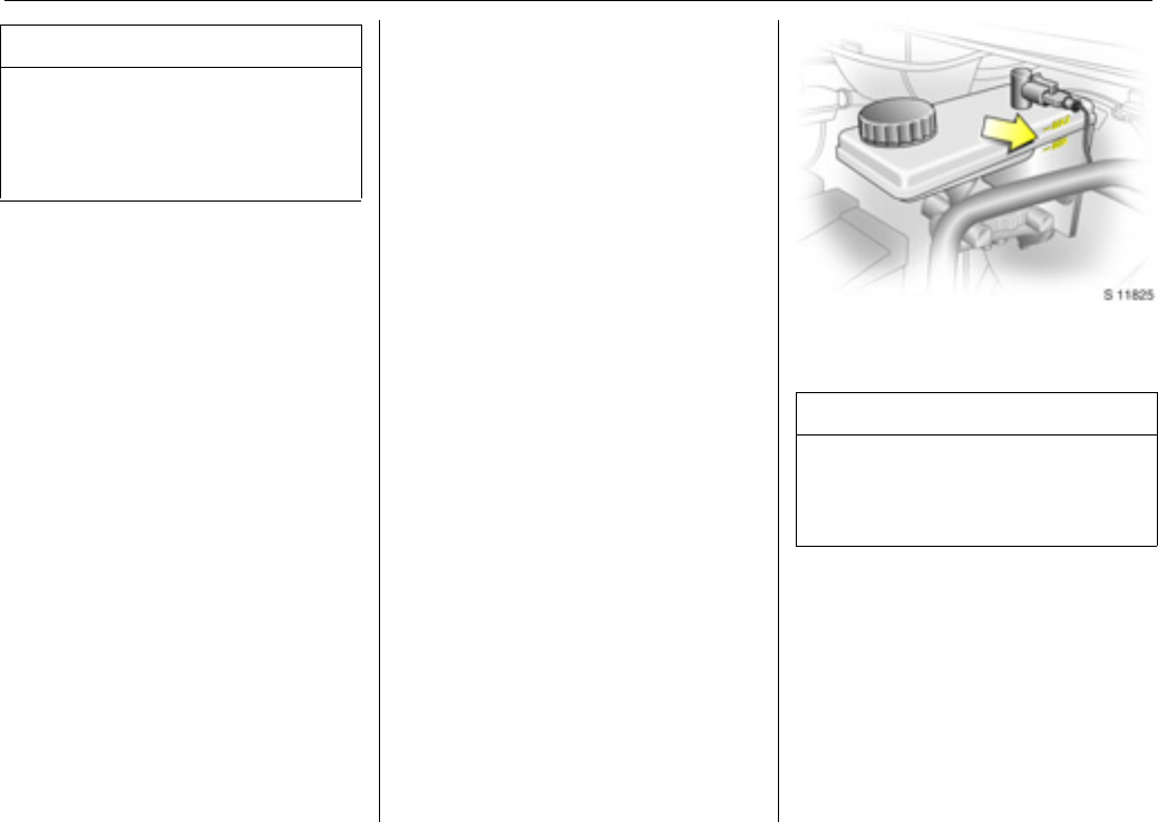
Belt tensioners
The seat belt systems incorporate belt
tensioners. In the event of a front or rear
impact the belt buckles are pulled
downwards; the diagonal and la p belts are
instantaneously tightened.
Actuation of belt tensioners
The belt tensioners must be replaced after
activation by a workshop.
The seat belts remain fully operational
even when the belt tensioners have been
actuated.
9 Warning
The belt tensioners are operational only
when the control indicator is unlit.
Seats, interior38
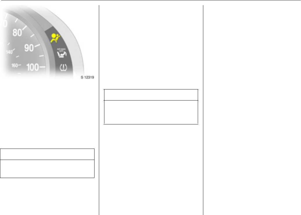
Belt tensioners control indicator v
The seat belt tensioners are monitored
ele ctronic ally together with the airbag, and
their operational readiness shown by the
control indicator in the instrument cluster.
When the ignition is switched on, the
control indicator v illuminates, then
extinguishes. If it does not illuminate or if it
illuminates while driving, there is a fault in
the airbag system or the belt tensioners
(also see page 50).
The system’s integrated self-diagnostics
allows faults to be quickly remedied.
Important
zAccessories not released for your vehicle
type and other objects must not be fixed
or placed within the action zone of the
belt tensioners as they may result in
injury if the belt tensioners are triggered.
zDo not make any modifications to the
components of the belt tensioners, as
this may result in unintended actuation
of the belt tensioners, rendering the
vehicle unroadworthy and causing
serious personal injury.
zThe belt tensioner and airbag system
control electronics can be found in the
centre console area. In order to avoid
malfunctions, do not store magnetic
objects in this area.
zWe recommend that you have the front
seats removed by a workshop in the
event of actuation of the belt tensioners.
zWhen using the rear seats, ensure that
the front seat belt components are not
damaged by shoes or other objects.
Avoid dirt getting in the retractors.
zThe belt tensioners only actuate once,
indicated by continuous illumination of
control indicator v in the instrument
cluster. Deployed belt tensioners must be
replaced by a workshop.
zWhen disposing of the vehicle, please
observe the applicable safety
regulations. Please have the vehicle
disposed of by a company which reuses
vehicle parts.
9 Warning
Have the cause of the fault remedied by
a workshop.
9 Warning
Improper handling (e.g. removal or
installation) can activate the belt
tensioners – risk of injury.
Seats, interior39
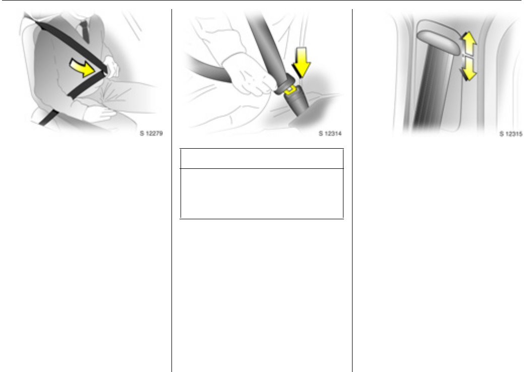
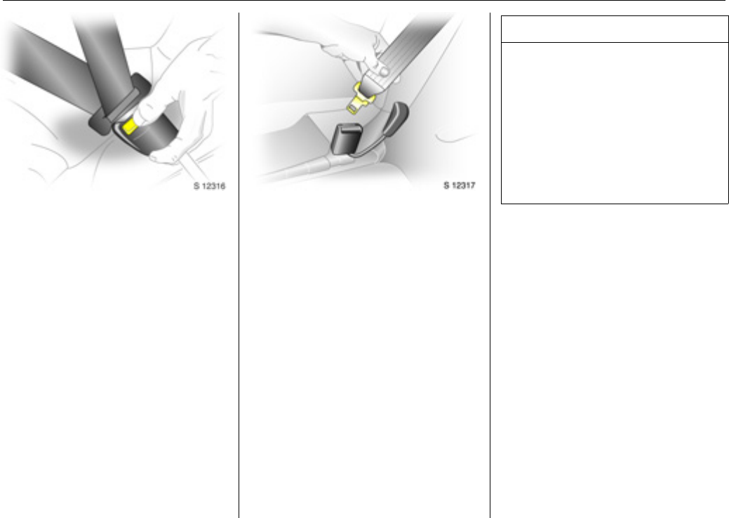
Using the belts
Fitting the belt
Pull the belt out evenly from the retractor
and guide it across the body, making
certain that it is not twisted.
Insert the latch plate into the buckle. The
seat backrest must not be tilted back too
far; the recommended angle of inclination
is approx. 25°. The lap belt must not be
twisted and must fit snugly across the
body. Tension the belt frequently while
driving by tugging the diagonal part of the
belt.
Bulky clothing prevents the belt from fitting
properly. The belt must not rest against
hard or fragile objects in the pockets of
your clothing (e.g. ballpoint pens, keys,
spectacles) because these could cause
injury. Do not place any objects (e.g.
handbags) between the belt and your
body.
Upper anchorage point
heightadjustment3
zDo not adjust height while driving,
zslide adjuster up or down to desired
position.
Adjust height such that the belt passes
over the wearer’s shoulder and rests
against the shoulder. It must not pass over
the neck or upper arm.
9 Warning
On pregnant women in particular the lap
belt must be positioned as low as
possible across the pelvis in order to
prevent pressure on the abdomen.
Seats, interior40
Removing the belt
To remove the belt, depress the red button
on the buckle; the belt will retract
automatically.
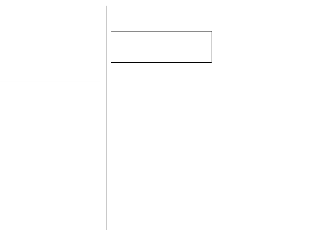
Two-latch belt 3
Before fitting the belt, first insert lower
latch plate into the buckle on the outside of
the seat.
The belt can now be used in the same way
as a standard seat belt.
9 Warning
The seat belt will not be effective in the
event of an accident if the lower latch is
not correctly fitted.
When releasing the seat belt, ensure that
the central buckle is always released
before the buckle on the side of the seat.
Always remove the lower latch plate from
the outside buckle before removing seats
from the vehicle or to facilitate access to
the rear seats 3 - see page 33.
Seats, interior41
Child restraint systems 3
Vauxhall child restraint systems are
designed specifically for your vehicle and
thus provide optimum safety for your child
in the event of impact. The use of a
Vauxhall child restraint system is therefore
recommended.
Selecting the right system
Your child should be transported facing
rearwards in the vehicle as long as
possible. It is appropriate to change the
system when the child’s head can no longer
be properly supported at eye height. The
child’s neck area is still very weak and in an
accident they suffer less stress in the semi-
prone rearward position than when sitting
up right.
Note
zChildren under 12 years or under 150 cm
tall should only travel in an appropriate
child restraint.
zWhen transporting children, use the child
restraint systems suitable for the child's
weight.
zEnsure that the child restraint system to
be installed is compatible with the
vehicle type.
zThe fabric cover of the Vauxhall child
restraint system can be wiped clean with
a damp cloth.
zDo not stick anything on the child
restraint systems and do not cover them
with any other materials.
zA child restraint system which has been
subjected to stress in an accident must
be replaced.
zEnsure that the mounting location of the
child restraint system within the vehic le is
correct.
zYou should also observe the instructions
on installation and use supplied with the
child restraint system.
9 Warning
While using a child restraint system on
the front passenger’s seat, the airbag
systems for the front passenger’s seat
must be deactivated (see page 51);
if not, the triggering of the front or side
airbag poses the risk of fatal injury to the
child.
This is especially the case if rearward-
facing child restraint systems are used on
the front passenger’s seat.
Seats, interior42
The following Vauxhall child restraint
systems have been approved for
installation in your Vivaro:
If child restraint systems of other
manufacture are to be installed, ensure
that they conform to the appropriate
safety regulations.
The country in which you are travelling
may prohibit child restraint installation in
certain locations. Always observe local or
national regulations.
Group, weight and age
class
1)
1)
We recommend the use of each system
until the child reaches the upper weight
limit .
Vauxhall
system
0
0+
From birth - 10 kg,
0 - 10 months
From birth - 13 kg,
0 - 2 years
Baby Safe
IFrom 9 - 18 kg,
8 months - 4 years
Duo ISOFIX
II
III
from 15 - 25 kg,
3 years - 7 years
from 22 - 36 kg,
6 years - 12 years
Kid
9 Warning
Disregard of these instructions may lead
to injuries or endanger life.
Seats, interior43
Front seats - all model variants
Group, weight and age class
Fa cing
direction
Single seat - front passenger
1)
1)
If adjusta ble, ens ure seat is in its r earmo st po sition. Make sure vehicle s eat b elt is as straight a s pos sib le b etw een sh oulder and upper anchorage point.
Bench seat - front passenger
without
airbag
with airbag
- no side
airbag
with side
airbag
without airbag with airbag
centreoutercentreouter
0:
0+:
up to 10 kg or approx. 10 months
up to 13 kg or approx. 2 years
RearwardUU
2)
2)
Ensure the front passenger’s airbag system is deactivated when installing a child restraint in this position. See page 51.
U
2)
X
U
XU
2)
I:9 to 18 kg or approx. 8 months - 4 yearsForwardUU
2)
U
2)
UFUUFU
2)
II:
III:
15 to 25 kg or approx. 3 - 7 years
22 to 36 kg or approx. 6 - 12 years
ForwardUU
2)
U
2)
UFUUFU
2)
U =Suitable for universal category child restraint systems for use in this mass group, in conjunction with three-point seat belt.
UF =Suitable for universal category forward-facing child restraint systems for use in this mass group, in conjunction with three-point seat belt.
X=Seat position not suitable for children of this mass group.
9 Warning
While using a child restraint system on the front passenger’s seat, the airbag systems for the front passenger’s seat must be deactivated
(see page 51); if not, the triggering of the front or side airbag poses the risk of fatal injury to the child.
This is especially the case if rearward-facing child restraint systems are used on the front passenger’s seat.
44Seats, interior
Combi - rear seats
Group, weight and age class
Facing
direction
2nd row bench seat 3rd row bench seat
Outer Centre Outer Centre
0:
0+:
up to 10 kg or approx. 10 months
up to 13 kg or approx. 2 years
Rearward
U
U,+XX
I:9 to 18 kg or approx. 8 months - 4 yearsForward
UU,+
X
X
II:
III:
15 to 25 kg or approx. 3 - 7 years
22 to 36 kg or approx. 6 - 12 years
ForwardU
U
X
X
U =Suitable for universal category restraint systems for use in this mass group, in conjunction with three-point seat belt.
L =Suitable only for specifically approved child restraints. Vauxhall has approved child restraint systems from the ’Baby-safe’, ’Duo-ISOFIX’ and ’Kid’
ranges.
+=Seat w ith ISOFIX mou nting a vailable. Wh en m ountin g ISOFIX, only ISOFIX ch ild restraint systems that h ave been appro ved for the vehicle may be used.
X=Seat position not suitable for children of this mass group.
Seats, interior45
Tour - rear seats
Group, weight and age class
Facing
direction
2nd row bench seat 3rd row bench seat
Outer Centre Outer Centre
0:
0+:
up to 10 kg or approx. 10 months
up to 13 kg or approx. 2 years
Rearward
U
U,+XX
I:9 to 18 kgor approx. 8 months - 4 yearsForward
U
U,+X
X
II:
III:
15 to 25 kg or approx. 3 - 7 years
22 to 36 kg or approx. 6 - 12 years
ForwardUUX
X
U =Suitable for universal category child restraint systems for use in this mass group, in conjunction with three-point seat belt.
L =Suitable only for specifically approved child restraints. Vauxhall has approved child restraint systems from the ’Baby-safe’, ’Duo-ISOFIX’ and ’Kid’
ranges.
+=Seat with ISOFIX mounting available. When mounting ISOFIX, only ISOFIX child restraint systems that have been approved for the vehicle may be used.
X=Seat position not suitable for children of this mass group.
46Seats, interior
Double Cab - rear seats
Group, weight and age class
Facing
direction
Rear bench seat
Outer Centre
0:
0+:
up to 10 kg or approx. 10 months
up to 13 kg or approx. 2 years
Rearward
XX
I:9 to 18 kg or approx. 8 months - 4 yearsForward
XX
II:
III:
15 to 25 kg or approx. 3 - 7 years
22 to 36 kg or approx. 6 - 12 years
ForwardX
X
X=Seat position not suitable for children of this mass group.
Seats, interior47
Airbag systems
Front airbags
The front airbag system is identified by the
word “Airbag” on the steering wheel and
above the glove compartment 3.
The front airbag system comprises:
zAn airbag with an inflator in the steering
wheel, and a second one behind the trim
panel above the glove compartment 3.
zThe control electronics with impact
sensor.
zThe airbag system control indicator v in
the instrument cluster.
zFront passenger airbag deactivation 3.
The front airbag system is triggered:
zDepending on the severity of the
accident.
zDepending on the type of impact.
zWithin the range shown in illustration
S11741.
zIndependently of the side airbag 3 and
curtain airbag systems 3.
Examples:
zImpact against a non-yielding obstacle:
the front airbag is triggered at low
vehicle speed.
zImpact against a yielding obstacle (such
as another vehicle): the front airbag is
only triggered at a higher vehicle speed.
When triggered, the driver’s airbag and
front passenger’s airbag 3 inflate in
milliseconds and form safety cushions for
the driver and front passenger. The
forward movement of the driver and front
passenger is checked and the risk of
injuries to the upper body and head are
thereby substantially reduced.
zNo impairment of view will occur,
because the airbags inflate and deflate
so quickly.
9 Warning
The front airbag system provides
optimum protection when the seat,
backrest and head restraint are correctly
adjusted. Adjust the driver's seat
according to the occupant's height such
that with the driver sitting upright, the
steering wheel is held in the area of its
upper spokes with the driver's arms
slightly bent. The front passenger’s seat
should be as far back as possible, with
the backrest upright. Do not place the
head, body, ha nds or feet on the cover of
the airbag system.
Do not place any objects in the area in
which the airbags inflate.
The three-point seat belt must be
correctly fitted (see page 39).
Seats, interior48
The front airbag system will not be
triggered in the event of:
zThe ignition being switched off.
zMinor frontal collisions.
zAccidents in which the vehicle overturns.
zCollisions involving a side or rear-impact
where it would not be of benefit to the
occ upants.
Side airbags 3
The side airbags are mounted on the
outboard sides of the front seat backrests
to protect the occupants in the event of a
severe side-impact.
The side airbag system comprises:
zAn airbag with inflator in the back of the
driver's and front passenger's seat
respectively.
zThe control electronics.
zSide-impact sensors.
zThe airbag systems control indicator v in
the instrument cluster.
The side airbag system will be triggered:
zDepending on the severity of the
accident,
zDepending on the type of impact.
zWithin the range shown in illustration
S11743.
zIndependently of the front airbag
system.
9 Warning
Seat belts must therefore always be worn.
The front airbag system serves to
supplement the three-point seat belts. If
you do not wear your seat belt you risk
being seriously injured, or even thrown
from the vehicle, in the event of an
accident.
The belt helps to keep you in the correct
seating position, in which the front airbag
system will provide you with effective
protection in the event of an accident.
Seats, interior49
When triggered the side airbag inflates in
milliseconds and forms a safety cushion for
driver and/or front passenger in the
respective door area. The risk of injury to
the upper body in the event of a side-
impact is thereby substantially reduced.
The side airbags will not be triggered in the
event of:
zThe ignition being switched off,
zFrontal collisions.
zAccidents in which the vehicle overturns.
zCollisions involving a rear-impact.
zCollisions involving a side-impact outside
the passenger cell.
Curtain airbags 3
The curtain airbag system is identified by
the badge AIRBAG on the headlining trim.
The curtain airbag system comprises:
zAn airbag with inflator in the roof frame
on the driver’s and passenger’s side
respectively.
zThe control electronics.
zThe side-impact sensors.
zThe airbag systems control indicator v in
the instrument cluster.
The curtain airbag system will be triggered:
zDepending on the severity of the
accident.
zDepending on the type of impact.
zWithin the range shown in illustration
S11743.
zTogether with the side airbag system.
zIndependently of the front airbag
system.
9 Warning
There must be no objects in the area in
which the airbag inflates or in the area
between the seat backrests and the
vehicle body. Do not place the hands or
arms on the covers of the airbag systems.
Important information - see page 52.
The three-point seat belt must be
correctly fitted - see page 39.
Seats, interior50
When triggered the curtain airbag inflates
within milliseconds and provides a safety
barrier in the head area on the respective
side of the vehicle. This reduces the risk of
injury to the head considerably in the event
of a side-impact.
The curtain airbags will not be triggered in
the event of:
zThe ignition being switched off.
zFrontal collisions.
zAccidents in which the vehicle overturns.
zCollisions involving a rear-impact.
zCollisions involving a side-impact outside
the passenger cell.
Airbag control indicator v
The front airbag system, side airbag
system 3 and curtain airbag system 3 are
monitored electronically together with the
belt tensioners, and their operational
readiness shown by the control indicator v
in the instrument cluster. When the ignition
is switched on, the control indicator
illuminates then extinguishes. If it does not
illuminate, or if it illuminates while driving,
there is a fault in the airbag systems or the
belt tensioners.
The systems might not be triggered in the
event of an accident.
The system's integral self-diagnosis facility
allows faults to be quickly remedied.
9 Warning
There must be no objects in the area in
which the airbag inflates. Do not place
the hands or arms on the covers of the
airbag systems. Important information –
see page 52.
The three-point seat belt must always be
correctly fitted – see page 39.
9 Warning
Have the cause of the fault remedied by
a workshop.
Seats, interior51
Front passenger airbag
deactivation3
Front and side airbag systems must be
deactivated if a child restraint system is to
be mounted on the front passenger’s seat.
The belt tensioners as well as all airbag
systems for the driver’s seat remain active
when the front passenger seat’s airbag
systems are disengaged.
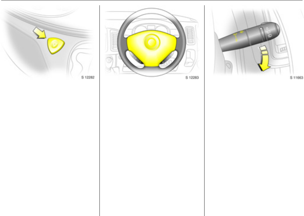
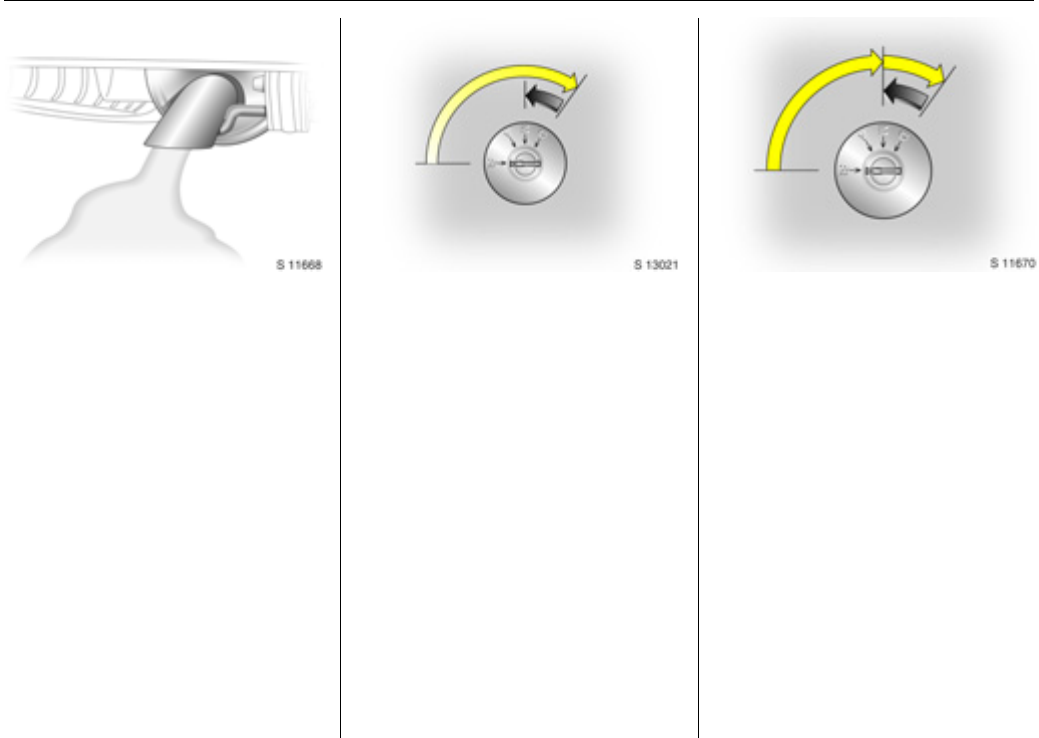
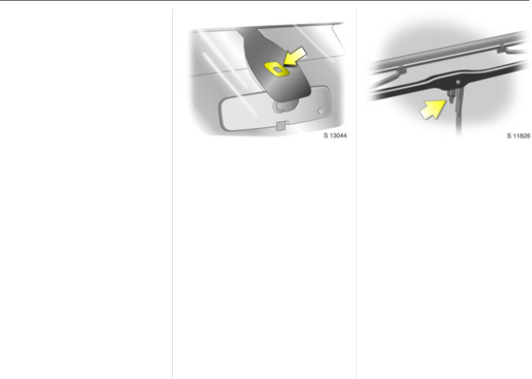
The switch for deactivating or activating
the airbag system is located on the front
passenger’s door.
The chosen setting remains active after the
ignition has been switched off. Control
indicator H for front passenger airbag
deactivation is located in the instrument
cluster.
To deactivate:
With the front passenger’s door open,
press switch in and rotate anticlockwise to
the "OFF" position.
The airbag systems for the front
passenger’s seat are now deactivated.
With the ignition switched on, the control
indicator H will remain illuminated to
indicate deactivation. It is now safe to
place a child restraint on the front
passenger’s seat.
Seats, interior52
To activate:
Ensure the airbag systems for the front
passenger’s seat are activated when a
passenger of adult size occupies the front
passenger’s seat.
With the front passenger’s door open,
press switch in and rotate clockwise to the
"ON" position. Front passenger’s airbag
systems are now activated and will be
triggered in the event of an accident.
Upon switching the ignition on, control
indicatorH will illuminate briefly and then
extinguish, indicating that the front
passenger’s airbag is active.
If control indicator H remains illuminated
in conjunction with control indicator v, this
indicates a fault within the system.
Important
zAccessories not released for your vehicle
type and other objects must not be
affixed or placed in the area in which the
airbags inflate, as they could cause
injury when the airbags are triggered.
zDo not place any objects between the
airbag systems and the vehicle
occupants; risk of injury.
zDo not stick or place anything on the
steering wheel, instrument panel, front
seat backrests in the vicinity of the
airbags and seat areas or cover them
with other materials.
zThe airbag systems and belt tensioner
control electronics can be found in the
centre console area. In order to avoid
malfunctions, do not store magnetic
objects in this area.
zUse only a dry cloth or Interior /
Upholstery Cleaner to clean the steering
wheel, instrument panel, front seat
backrests, roof frame and seat area of
the front passenger’s seat. Do not use
any aggressive cleaning agents.
zOnly protective covers which are
approved for your Vivaro with side
airbag 3 may be fitted on the front
seats. When fitting the protective covers,
make sure that the airbag units on the
outboard sides of the front seat
backrests are not covered.
zThe airbag systems are triggered
independently of each other depending
on the severity of the accident and the
type of im pact. The side airbag system 3
and the curtain airbag system 3 are
triggered together.
zEach airbag can be triggered only once.
Once triggered, an airbag must be
replaced without delay by a workshop.
zThe speeds, directions of movement and
deformation properties of the vehicles,
and the properties of the obstacle
concerned, determine the severity of the
accident and triggering of the airbags.
The degree of damage to your vehicle
and the resulting repair costs alone are
not indicative that the criteria for
triggering of the side airbag 3 were met.
9 Warning
Have the cause of the fault remedied by
a workshop.
Seats, interior53
zDo not perform any modifications to the
components of the airbag systems, as
this will render the vehicle unroadworthy.
zWe recommend having the steering
wheel, the instrument p ane l, all panelling
parts, the door seals, the handles and
the front seats removed by a workshop
in the event of triggering of the airbags.
zWhen disposing of the vehicle, please
observe the applicable safety
regulations. Please have the vehicle
disposed of by company which reuses
vehicle parts.
The system for deactivating the front
passenger seat’s airbag systems is
indicated a sticker on the side of the
instrument panel, visible when passenger’s
door is open.
9 Warning
The systems can be triggered abruptly
and cause injury if they are handled
imp ro p er ly.
9 Warning
Child restraint systems as well as other
heavy objects must never be carried on
the lap of passengers; risk of fatal injury.
9 Warning
While using a child restraint system on
the front passenger’s seat, the airbag
systems for the front passenger’s seat
must be deactivated; if not, the
triggering of the front or side airbag
poses the risk of fatal injury to the child.
This is especially the case if rearward-
facing child restraint systems are used on
the front passenger’s seat.
Seats, interior54
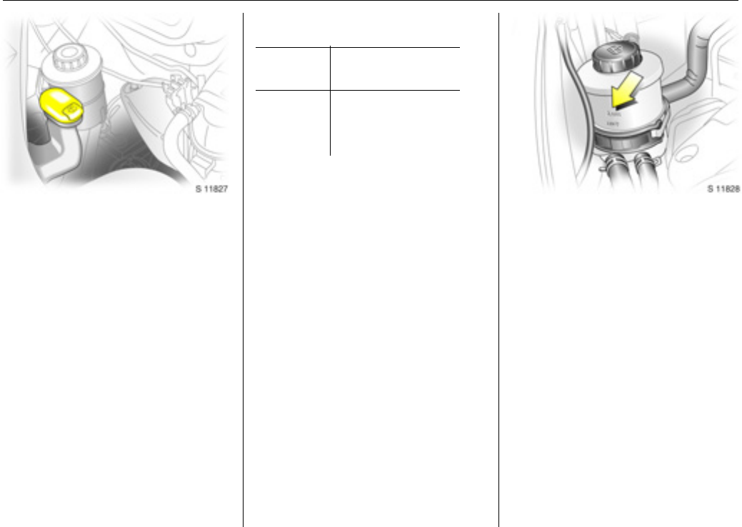
Load compartment net 3
The load compartment net can be fitted
behind the front or rear seats to separate
compartments when transporting luggage
or animals.
Installing (front or rear position)
Lift the covers to access the mountings,
insert the load compartment net rod into
the mounts and secure. Attach the straps
to the lashing eyes behind the front seats;
or to the rings on the rear seat frame, then
tension the straps.
Removing
Tilt strap length adjuster upwards and
unhook strap.
Load compartment cover 3
To remove:
Lift cover and disconnect from the side
guides.
Notes on loading
See page 56.
9 Warning
Loose objects in the load compartment
should be secured safely.
9 Warning
Do not place any heavy or sharp objects
on the cover.
Loose objects in the load compartment
should be secured safely.
Seats, interior55
Lashing eyes
Lashing eyes are mounted in the load
compartment to enable loads to be
secured in position using lashing straps 3
or a luggage floor net 3.
The maximum force applied to the lashing
eyes should not exceed 5000 N at 30°.
Load anchorage rails 3
Load anchorage rails mounted in the load
compartment, provide adjustable
anchorage points for securing loads.
zRelease centre pin of the anchorage
point, by pulling out against spring
tension,
zslide the anchorage point to the required
location,
zposition the anchorage point directly
over the nearest suitable "locking hole",
zrelease the centre pin of the anchorage
point, ensuring the pin is located
correctly and the anchorage point is
securely locked,
zloads can then be secured in position
using lashing straps 3 attached to the
anchorage point.
The maximum load of each anchorage
point is 75 kg. To prevent the possibility of
exceeding this maximum, the use of
ratchet type lashing straps is to be
avoided.
9 Warning
Loose objects in the load compartment
should be secured safely.
Seats, interior56
Notes on loading the vehicle
zHeavy objects in the load compartment
should be placed as far forwards as
possible. If objects are to be stacked, the
heavier objects should be placed at the
bottom. Unsecured objects in the load
compartment would be thrown forwards
with great force in the event of heavy
braking, for example.
zSecure heavy objects with lashing
straps 3attached to the lashing eyes.
If heavy loads slip when the vehicle is
braked heavily or driven around a bend,
the handling of the vehicle may change.
zSecure loose items in load compartment
using luggage floor net 3, to prevent
sliding.
zWhen transporting objects in the load
compartment, fit load compartment
net3 - see page 54.
zClose the load compartment cover 3, to
prevent the objects from being reflected
in the rear wind ow .
zIf the rear seats are not folded down 3 or
re move d 3 when transporting objects in
the load compartment, they must be
engaged in their upright position -
seepage 34.
zThe warning triangle 3 and first-aid kit 3
should always be freely accessible.
zNo objects should be placed on the load
compartment cover 3 or the instrument
panel. They are reflected in the glass,
obstruct the driver’s view and will be
thrown through the vehicle in the event
of heavy braking, for example.
zNo objects should be stored in any of the
airbag 3 inflation zones, as injuries may
be caused when the airbag is triggered.
zT he lo ad mus t not obs tru ct th e operatio n
of the pedals, handbrake and gearshift
lever, or hinder the freedom of
movement of the driver. Do not place
any unsecured objects in the interior.
zBulky objects should not be transported
with the rear doors open or ajar,
otherwise poisonous exhaust fumes may
enter the vehicle. In addition, the number
plate is only distinguishable and
illuminated correctly if the doors are
closed.
zWeights, payload and roof load -
seepage166.
zDriving with a roof load (also see
page97) increases the sensitivity of the
vehicle to crosswinds and has a
detrimental effect on vehicle handling
owing to the higher centre of gravity of
the vehicle.
9 Warning
Disregard of these instructions may lead
to injuries or endanger life. Vehicle
passengers must be informed
accordingly.
Seats, interior57
Over-cab storage area 3
The total weight in this compartment must
not exceed 30 kg.
Ashtray
Removable to enable universal use for
driver or passengers.
To be used only for ash and not for
combustible rubbish.
To open: lift up the cover.
To empty: remove the ashtray from the
drink holder recess and empty.
Drink holders
To use drink holders, remove the ashtray
unit.
9 Warning
Disregard of these instructions may lead
to injuries or endanger life. Vehicle
passengers must be informed
accordingly.
Seats, interior58
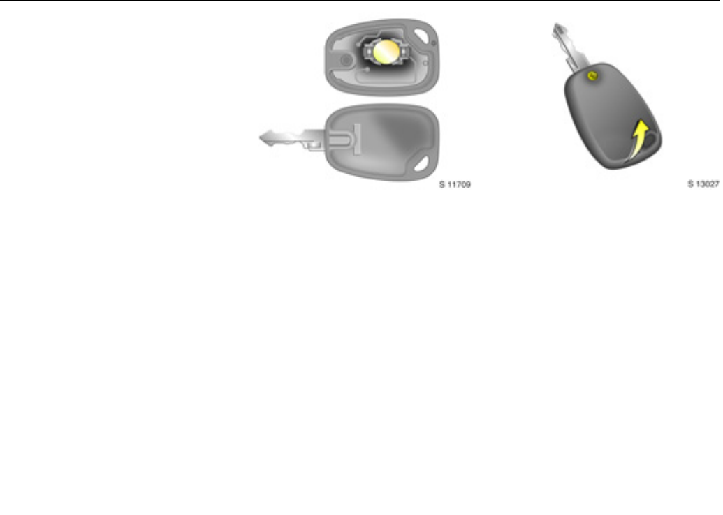
Warning triangle ¨3,
First-aidkit+3
Your first-aid kit and warning triangle can
be accommodated in the space under the
front seats.
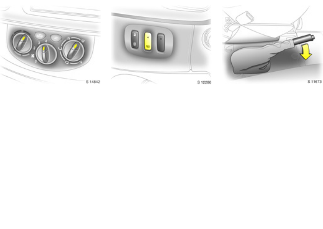
Power outlets
Cigarette lighter )
With ignition switched on, press in the
cigarette lighter. Heating up ceases once
element is glowing. Withdraw lighter.
Accessory socket
The socket for the cigarette lighter can be
used to connect electrical acc essories when
the ignition is switched on.
An ad ditional acce ssory socket 3 is located
in the rear of the vehicle.
When the engine is not running, using these
accessory sockets will cause the battery to
be discharged.
The maximum power requirement of
electrical accessories must not exceed
120watts.
Do not connect any current-delivering
accessories, e.g. electrical charging
devices or batteries.
Connected electrical accessories must
comply with the EC standard in terms of
electromagnetic compatibility
requirements laid down in DIN VDE 40 839,
otherwise vehicle malfunctions may occur.
The use of non-authorised accessories may
cause damage to the socket.
9 Warning
Ensure items stowed under the seats are
securely restrained.
Instruments, controls59
Instruments, controls
Control indicators...............................59
Gebruikershandleiding.com neemt misbruik van zijn services uitermate serieus. U kunt hieronder aangeven waarom deze vraag ongepast is. Wij controleren de vraag en zonodig wordt deze verwijderd.
Product:
Spelregels forum
Om tot zinvolle vragen te komen hanteren wij de volgende spelregels:
lees eerst de handleiding door;
controleer of uw vraag al eerder door iemand anders is gesteld;
probeer uw vraag zo duidelijk mogelijk te stellen;
heeft u een probleem en al geprobeerd om dit op te lossen, vermeld dit erbij aub;
heeft u een oplossing gekregen van een bezoeker dan horen wij dat graag in dit forum;
wilt u een reactie geven op een vraag of antwoord, gebruik dan niet dit formulier maar klik op de knop 'reageer op deze vraag';
uw vraag wordt direct op de website gezet; vermijd daarom persoonlijke gegevens in te vullen;
Belangrijk! Als er een antwoord wordt gegeven op uw vraag, dan is het voor de gever van het antwoord nuttig om te weten als u er wel (of niet) mee geholpen bent! Wij vragen u dus ook te reageren op een antwoord.
Belangrijk! Antwoorden worden ook per e-mail naar abonnees gestuurd. Laat uw emailadres achter op deze site, zodat u op de hoogte blijft. U krijgt dan ook andere vragen en antwoorden te zien.
Abonneren
Abonneer u voor het ontvangen van emails voor uw Vauxhall Vivaro 2008 bij:
nieuwe vragen en antwoorden
nieuwe handleidingen
U ontvangt een email met instructies om u voor één of beide opties in te schrijven.
Ontvang uw handleiding per email
Vul uw emailadres in en ontvang de handleiding van Vauxhall Vivaro 2008 in de taal/talen: Engels als bijlage per email.
De handleiding is 3,02 mb groot.
U ontvangt de handleiding per email binnen enkele minuten. Als u geen email heeft ontvangen, dan heeft u waarschijnlijk een verkeerd emailadres ingevuld of is uw mailbox te vol. Daarnaast kan het zijn dat uw internetprovider een maximum heeft aan de grootte per email. Omdat hier een handleiding wordt meegestuurd, kan het voorkomen dat de email groter is dan toegestaan bij uw provider.
Stel vragen via chat aan uw handleiding
Stel uw vraag over deze PDF
Uw handleiding is per email verstuurd. Controleer uw email
Als u niet binnen een kwartier uw email met handleiding ontvangen heeft, kan het zijn dat u een verkeerd emailadres heeft ingevuld of dat uw emailprovider een maximum grootte per email heeft ingesteld die kleiner is dan de grootte van de handleiding.
Er is een email naar u verstuurd om uw inschrijving definitief te maken.
Controleer uw email en volg de aanwijzingen op om uw inschrijving definitief te maken
U heeft geen emailadres opgegeven
Als u de handleiding per email wilt ontvangen, vul dan een geldig emailadres in.
Uw vraag is op deze pagina toegevoegd
Wilt u een email ontvangen bij een antwoord en/of nieuwe vragen? Vul dan hier uw emailadres in.