FULL LCD .................................................................................................................................................................... 8
CONTROL BUTTONS.................................................................................................................................................9
POWER SUPPLY......................................................................................................................................................13
PC INTERFACE .........................................................................................................................................................14
FEATURES AND DISPLAYS.......................................................................................................................................... 15
BAR GRAPHS........................................................................................................................................................... 16
OPERATING MODES AND SURFACE MODE.........................................................................................................22
NORM SURF MAIN ..............................................................................................................................................23
NORM/GAUGE SET MODES....................................................................................................................................24
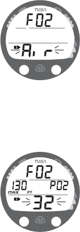
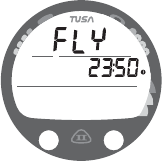
Setting FO2 for Nitrox Dives.................................................................................................................................25
SET F GROUP (FO2)................................................................................................................................................ 26
Set FO2 GAS 1..................................................................................................................................................... 27
Set FO2 GAS 2..................................................................................................................................................... 28
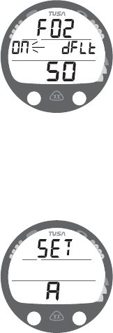
Set FO2 50% Default........................................................................................................................................... 29
4
CONTENTS (continued)
SET A GROUP (NORM/GAUG ALARMS)................................................................................................................ 29
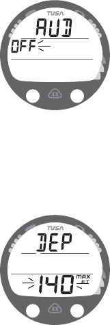
Set Audible Alarm................................................................................................................................................. 29
Set Depth Alarm...................................................................................................................................................30
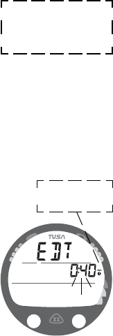
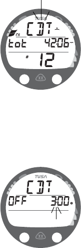
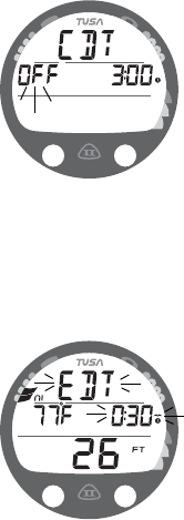
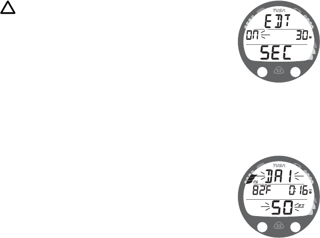
Set EDT (Elapsed Dive Time) Alarm...................................................................................................................31
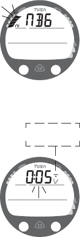
Set NiBG (Tissue Loading Bar Graph) Alarm.......................................................................................................32
Set DTR (Dive Time Remaining) Alarm................................................................................................................32
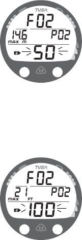
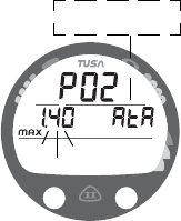
Set PO2 Alarm...................................................................................................................................................... 33
SET U GROUP (UTILITIES) ...................................................................................................................................... 34
Set Wet Activation ................................................................................................................................................ 34
Set Units of Measure ............................................................................................................................................ 35
Set Deep Stop...................................................................................................................................................... 35
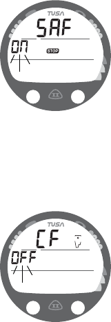
Set Safety Stop..................................................................................................................................................... 36
Set Conservative Factor ....................................................................................................................................... 36
Set Backlight Duration .......................................................................................................................................... 37
Set Sampling Rate................................................................................................................................................ 38
SET T GROUP (TIME/DATE).................................................................................................................................... 38
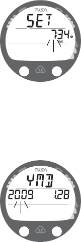
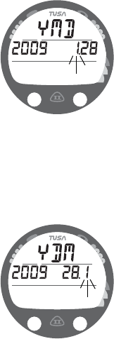
Set Date Format ................................................................................................................................................... 39
Set Time Format................................................................................................................................................... 39
Set Time................................................................................................................................................................40
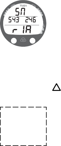
Set Date................................................................................................................................................................ 40
SERIAL NUMBER.....................................................................................................................................................42
NORM PLAN MODE..................................................................................................................................................43
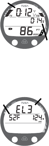
HISTORY MODE........................................................................................................................................................50
NORM NO DECO DIVE MODE .................................................................................................................................56
No Deco Deep Stop .............................................................................................................................................. 58
No Deco Safety Stop ............................................................................................................................................ 60
HIGH PO2 ..................................................................................................................................................................70
HIGH O2.................................................................................................................................................................... 71
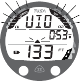
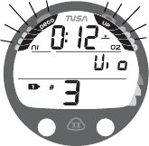
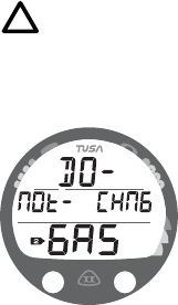
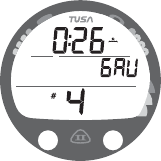
SWITCHING GAS MIXES ............................................................................................................................................... 73
NORM POST DIVE MODES ........................................................................................................................................... 77
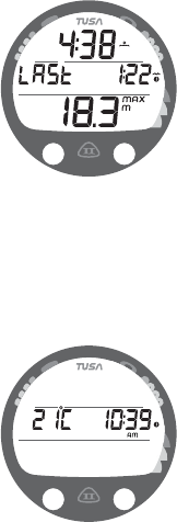
FIRST 10 MINUTES ON SURFACE .......................................................................................................................... 78
AFTER 10 MINUTES ON SURFACE........................................................................................................................ 79
UPLOADING SETTINGS AND DOWNLOADING DATA .......................................................................................... 80
DIGITAL GAUGE MODE........................................................................................................................................... 82
FREE DIVE MAIN AND ALTs .................................................................................................................................... 93
CARE AND CLEANING ........................................................................................................................................... 100
INSPECTIONS AND SERVICE...............................................................................................................................100
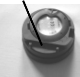
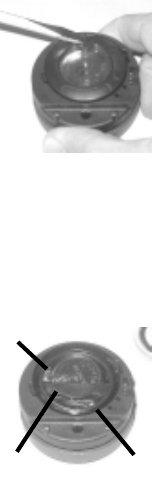
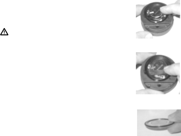
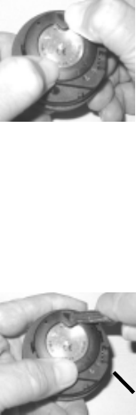
MODULE REMOVAL FROM BOOT........................................................................................................................101
INSPECTION/ SERVICE RECORD......................................................................................................................... 115
7
OVERVIEW
8
M
A
S
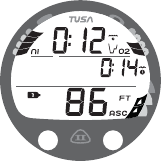
FULL LCD
Components:
a.Icon - Log Mode
b.NiBG (Nitrogen Bar Graph)
c.Icon - operating mode
Surface Interval
Plan NDC Time
No Deco Time Remaining
Deco Total Ascent Time
d.O2BG (O2 Bar Graph)
e.Icon - Stop Time Required
Elapsed Dive Time
f.Select (S) Button
g.Icon - Time of Day
h.Icon - Depth/Max Depth
i.ASC (Ascent Rate Indicator)
j.Advance (A) Button
k.Icon - Descend Arrow
Icon - Stop Bar
Icon - Ascend Arrow
l.Icon - Dive #
m. Mode (M) Button
n.Icon - Gas # (mix)
o.Icon - Low Battery
p.Icon - Max/Depth
q.Icon - Degrees
f
j
q
c
l
b
g
n
m
i
d
k
a
h
e
o
p
9
M
A
S
INTRODUCTION
Welcome to TUSA and thank you for choosing the Element II !
It is extremely important that you read this Owner's Manual in sequence and understand it
completely before attempting to use the Element II as a dive computer.
Remember that technology is no substitute for common sense, and a dive computer only
provides the person using it with data, not the knowledge to use it.
CONTROL BUTTONS
The Element II features three Control Buttons that allow you to select mode options and
access specific information. They are also used to enter Settings, activate the Backlight,
and acknowledge the Audible Alarm.
Throughout this manual they will be referred to as the M, A, and S buttons.
• Front/Left - Mode (M) button
• Front/Right - Advance (A) button
• Right/Side - Select (S) button
MA
S
10
S
S
S
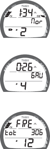
Fig. 2 - FREE MODE
Fig. 1B - GAUG MODE
Fig. 1A - NORM MODE
OPERATING MODES
The Element II features 3 Operating Modes, NORM (Fig. 1A)
which is used for Air and Nitrox SCUBA dives, GAUG (Fig. 1B)
used for SCUBA dives in which Nitrogen-Oxygen calculations
are not performed, and FREE (Fig. 2) used for activities that do
not use SCUBA.
> NORM Mode allows access to Fly, Desat, Log, and History
Modes, as well as entering settings.
> GAUG Mode is similar without access to Desat Mode.
> FREE Mode only allows access to specific Free Modes.
AUDIBLE ALARM
Most warning situations that activate the Audible Alarm while
operating in NORM or GAUG Mode cause the Element II to emit
1 beep per second for 10 seconds, or until the situation is
corrected, or it is acknowledged by momentarily pressing and
releasing the S button (less than 2 seconds).
After being acknowledged and the situation corrected, the Alarm
will sound again upon reentry into the warning situation, or entry
into another type of warning situation.
FREE Dive Mode has its own set of Alarms which emit 3 short
beeps either 1 or 3 times which cannot be acknowledged or set
Off.
11
Situations that will activate the NORM/GAUG 10 second Alarm include -
• Descent deeper than the Max Depth Set Point selected.
• Dive Time Remaining at the Set Point selected.
• Elapsed Dive Time at the Set Point selected.
• High PO2 of 1.60 ATA or the Set Point selected.
• High O2 of 300 OTU (single or daily exposure).
• Nitrogen Bar Graph at the segment Set Point selected.
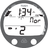
• NORM/GAUG Ascent Rate exceeds 60 FPM (18 MPM) when deeper than 60 FT (18
M), or 30 FPM (9 MPM) at 60 FT (18 M) and shallower.
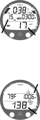
• Entry into Decompression Mode (Deco).
• Conditional Violation (above a required Deco Stop Depth for less than 5 minutes).
• Delayed Violation (above a required Deco Stop Depth for more than 5 minutes).
• Delayed Violation (a Deco Stop Depth greater than 60 FT/18 M is required).
• Delayed Violation (the Maximum Operating Depth of 330 FT/100 M in NORM, or
399 FT/120 M in GAUG, is exceeded).
• A Gas Switch would expose the diver to PO2 greater than 1.60 ATA.
A single short beep (which cannot be disabled) is emitted for the following -
• Upon completion of a battery change.
• Change from Delayed to Full Violation 5 minutes after the dive.
3 short beeps (which cannot be disabled) are emitted for the following -
• NORM/GAUG Ascent Rate is 51 to 60 FPM (15.1 to 18 MPM) when deeper than
60 FT (18 M), or 26 to 30 FPM (7.5 to 9 MPM) at 60 FT (18 M) and shallower.
• FREE Dive Elapsed Dive Time Alarm (3 beeps every 30 seconds if set On).
Gebruikershandleiding.com neemt misbruik van zijn services uitermate serieus. U kunt hieronder aangeven waarom deze vraag ongepast is. Wij controleren de vraag en zonodig wordt deze verwijderd.
Product:
Spelregels forum
Om tot zinvolle vragen te komen hanteren wij de volgende spelregels:
lees eerst de handleiding door;
controleer of uw vraag al eerder door iemand anders is gesteld;
probeer uw vraag zo duidelijk mogelijk te stellen;
heeft u een probleem en al geprobeerd om dit op te lossen, vermeld dit erbij aub;
heeft u een oplossing gekregen van een bezoeker dan horen wij dat graag in dit forum;
wilt u een reactie geven op een vraag of antwoord, gebruik dan niet dit formulier maar klik op de knop 'reageer op deze vraag';
uw vraag wordt direct op de website gezet; vermijd daarom persoonlijke gegevens in te vullen;
Belangrijk! Als er een antwoord wordt gegeven op uw vraag, dan is het voor de gever van het antwoord nuttig om te weten als u er wel (of niet) mee geholpen bent! Wij vragen u dus ook te reageren op een antwoord.
Belangrijk! Antwoorden worden ook per e-mail naar abonnees gestuurd. Laat uw emailadres achter op deze site, zodat u op de hoogte blijft. U krijgt dan ook andere vragen en antwoorden te zien.
Abonneren
Abonneer u voor het ontvangen van emails voor uw Tusa Element II SCA362 bij:
nieuwe vragen en antwoorden
nieuwe handleidingen
U ontvangt een email met instructies om u voor één of beide opties in te schrijven.
Ontvang uw handleiding per email
Vul uw emailadres in en ontvang de handleiding van Tusa Element II SCA362 in de taal/talen: Engels als bijlage per email.
De handleiding is 4,9 mb groot.
U ontvangt de handleiding per email binnen enkele minuten. Als u geen email heeft ontvangen, dan heeft u waarschijnlijk een verkeerd emailadres ingevuld of is uw mailbox te vol. Daarnaast kan het zijn dat uw internetprovider een maximum heeft aan de grootte per email. Omdat hier een handleiding wordt meegestuurd, kan het voorkomen dat de email groter is dan toegestaan bij uw provider.
Stel vragen via chat aan uw handleiding
Stel uw vraag over deze PDF
Uw handleiding is per email verstuurd. Controleer uw email
Als u niet binnen een kwartier uw email met handleiding ontvangen heeft, kan het zijn dat u een verkeerd emailadres heeft ingevuld of dat uw emailprovider een maximum grootte per email heeft ingesteld die kleiner is dan de grootte van de handleiding.
Er is een email naar u verstuurd om uw inschrijving definitief te maken.
Controleer uw email en volg de aanwijzingen op om uw inschrijving definitief te maken
U heeft geen emailadres opgegeven
Als u de handleiding per email wilt ontvangen, vul dan een geldig emailadres in.
Uw vraag is op deze pagina toegevoegd
Wilt u een email ontvangen bij een antwoord en/of nieuwe vragen? Vul dan hier uw emailadres in.