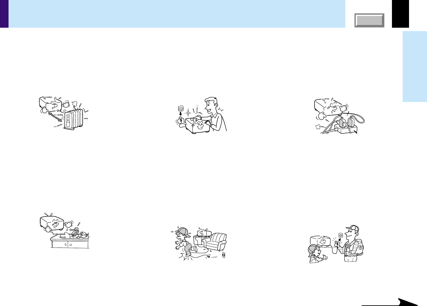
Openings in the cabinet are provided for ventilation and to
ensure reliable operation of the product and to protect it from
overheating, and these openings must not be blocked or
covered.
The explanation here is only for the model without the document
imaging camera. For the model with the document imaging camera,
refer to
53
.
Note
The air exhaust discharges high temperature air. Do not put anything around the air exhaust, otherwise it may deform due to the high temperature air.
12
Before use
CONTENTS
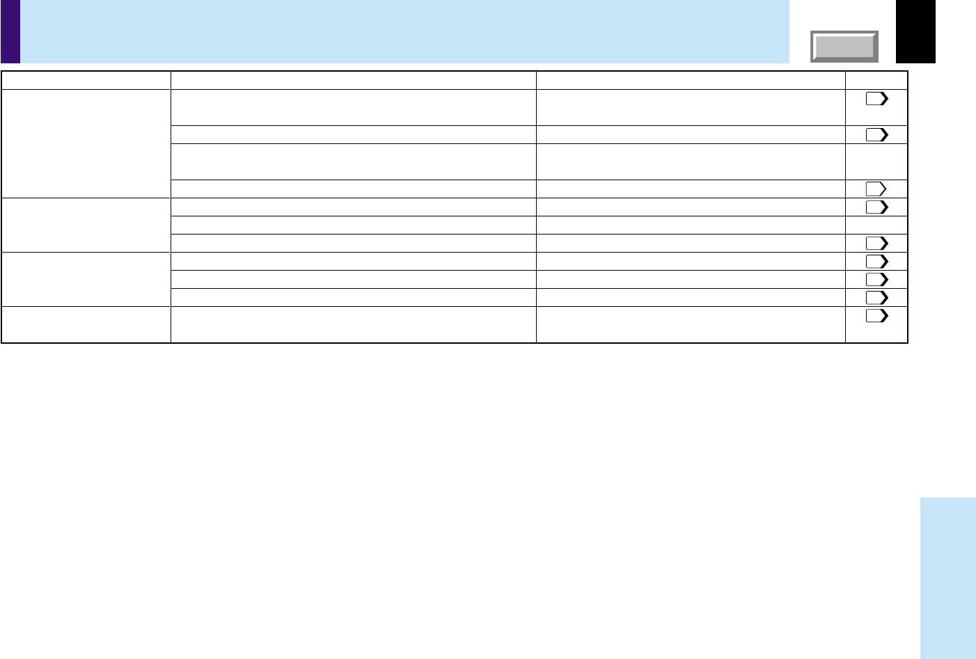
Names of each part on the main unit (continued)
34
33
4231
273260
60
273260
273260
3227
43
37
42
29
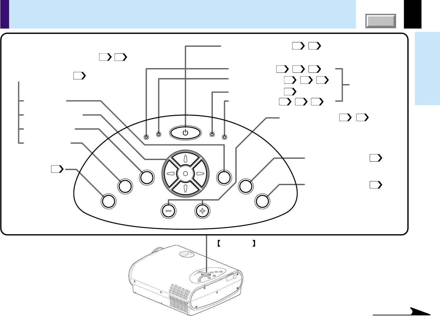
TEMP indicator
KEYSTONE button
To correct the keystone distortion of
the picture.
FAN indicator
LAMP indicator
ON indicator
INPUT button
ENTER button
Selection buttons
EXIT button
VOL/ADJ buttons
AUTO SET button
MENU button
ON/STANDBY button
Top side
Control panel
To set and/or adjust values on the menu.
To adjust the volume when the menu is not
displayed.
To indicate the
status of the
projector.
To turn the projector on or off (standby).
To display the menu screen and/or select
operations on the menu screen.
Use the selection buttons and the EXIT button
to enlarge the image.
To adjust the computer input image
automatically.
To select the input source.
K
E
Y
S
T
O
N
E
A
U
T
O
S
E
T
E
X
I
T
ON / STANDBY
VOL / ADJ
E
N
T
E
R
M
E
N
U
I
N
P
U
T
F
A
N
T
E
M
P
L
A
M
P
O
N
Continued
13
Before use
CONTENTS
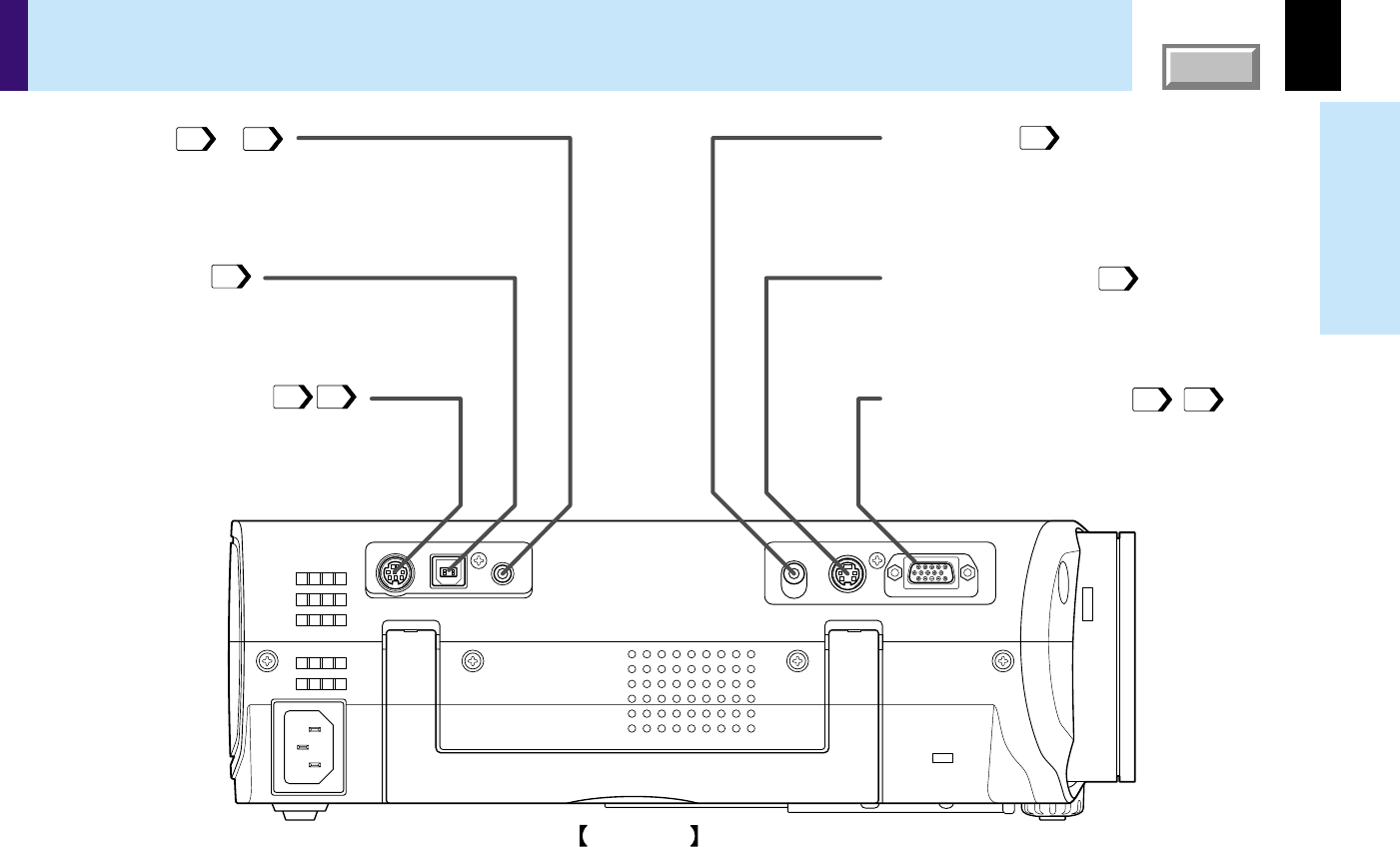
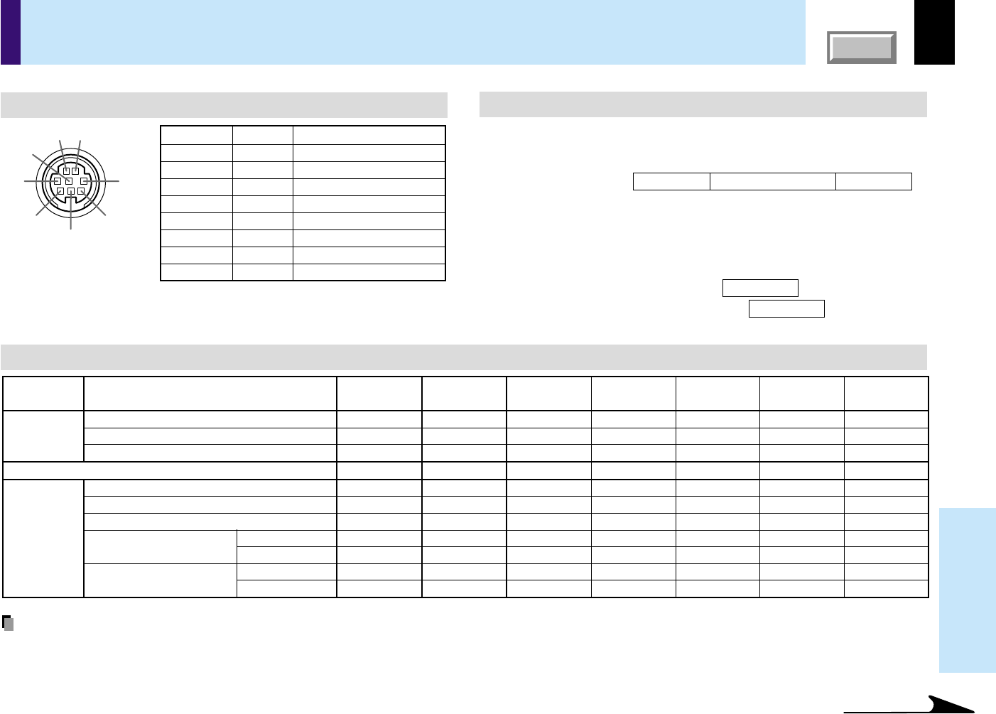
USBS-VIDEOVIDEOAUDIO
COMPUTER
(
Y/P
B
/P
R
)
CONTROL
AUDIO jack -
(ø 3.5mm stereo mini-jack)
To enter audio signal from a computer
or a video equipment.
USB connector
To connect to a USB connector of a
computer when using the presentation
mode.
CONTROL connector
(RS-232C connector)
To connect a computer to control the
projector.
VIDEO jack
To enter video signal from a video
equipment, etc.
S-VIDEO connector
To enter S-Video signal from video
equipment, etc.
COMPUTER connector
To enter RGB signal from a computer,
etc or component video signal (Y/P
B/PR
Signal) from a video equipment.
2325
24
24
2325
40
2671
Left side
Names of each part on the main unit (continued)
14
Before use
CONTENTS
Names of each part on the remote control
MENU
ON /
INPUT
ENTER
CT-90106
KEYSTONEAUTO SET
EXIT /
P.MODE
PIP
FREEZE
MUTE
CALL
RESIZE
VOL
/
ADJ
STANDBY
29
34
36
38
35
43
31
2732
33
37
39
37
4243
40
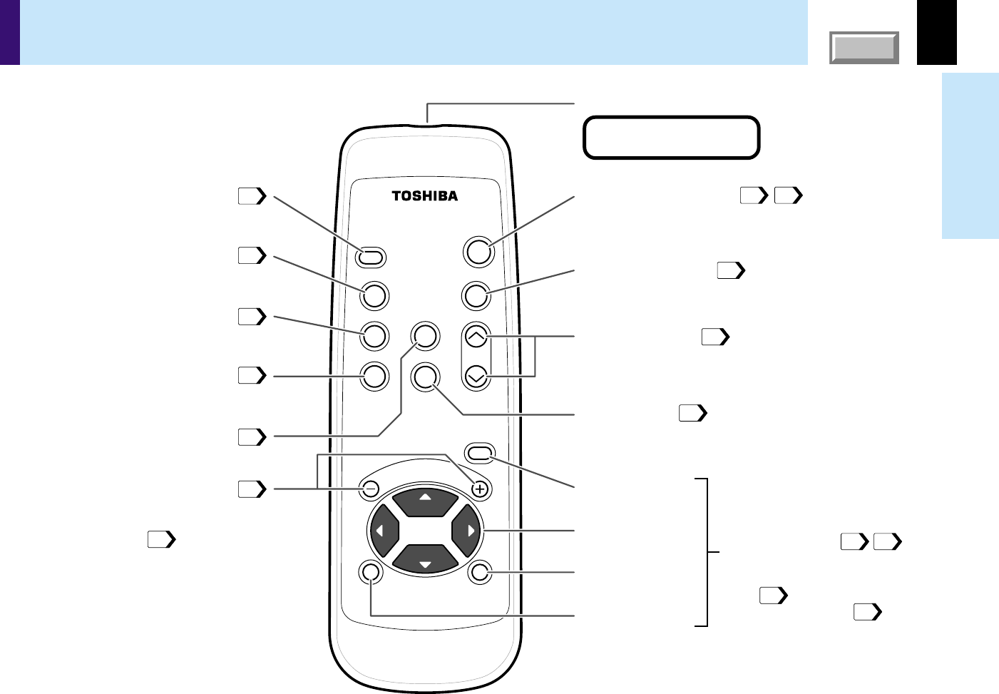
To display the menu screen
and/or select the operation
on the menu screen.
Use the selection buttons and
EXIT button to enlarge the
image and to operate
the presentation mode.
INPUT button
To select the input source.
KEYSTONE button
To correct the keystone distortion
of the picture.
FREEZE button
To freeze the picture.
PIP button
To display the video input image
as a small size picture in the
computer image display window.
VOL/ADJ buttons
To set and/or adjust values on the menu.
To adjust volume when the menu is not
displayed.
MUTE button
To cut off the picture and sound
temporarily.
AUTO SET button
ON/STANDBY button
Remote control transmission part
To turn the projector on or off (Standby).
To adjust the computer input image
automatically.
RESIZE buttons
To enlarge the picture size.
ENTER button
Selection button
EXIT button
MENU button
CALL button
To display the information.
CLASS 1 LED PRODUCT
15
Before use
CONTENTS
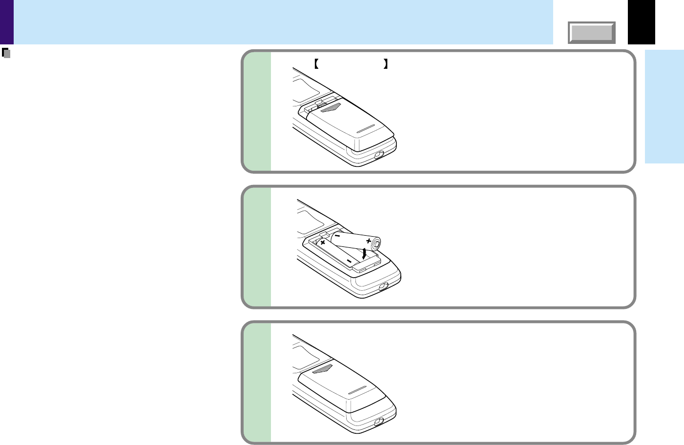
Loading batteries
Notes
Using batteries incorrectly can cause them to leak
or burst. Strictly observe the following.
•Install the batteries with their + and – ends facing
correctly.
•Do not charge, heat, disassemble, or short the
batteries or throw them into a fire.
•Do not leave any exhausted batteries in the
remote control.
•Do not mix different types of batteries or new and
old batteries.
•When you will not be using the remote control for
a prolonged period, take the batteries out of the
remote control.
•When the remote control stops working or only
works at very close range, replace all the batteries
with new ones.
•When replacing the batteries, use longer life
alkaline batteries.
•If a battery has leaked, carefully wipe off any
residue inside the battery case before loading new
batteries.
1
2
3
Open the cover.
Install the batteries.
Make sure that the +/– polarities match the
illustration in the compartment.
Attach the cover.
Bottom side
16
Before use
CONTENTS
Remote control operation
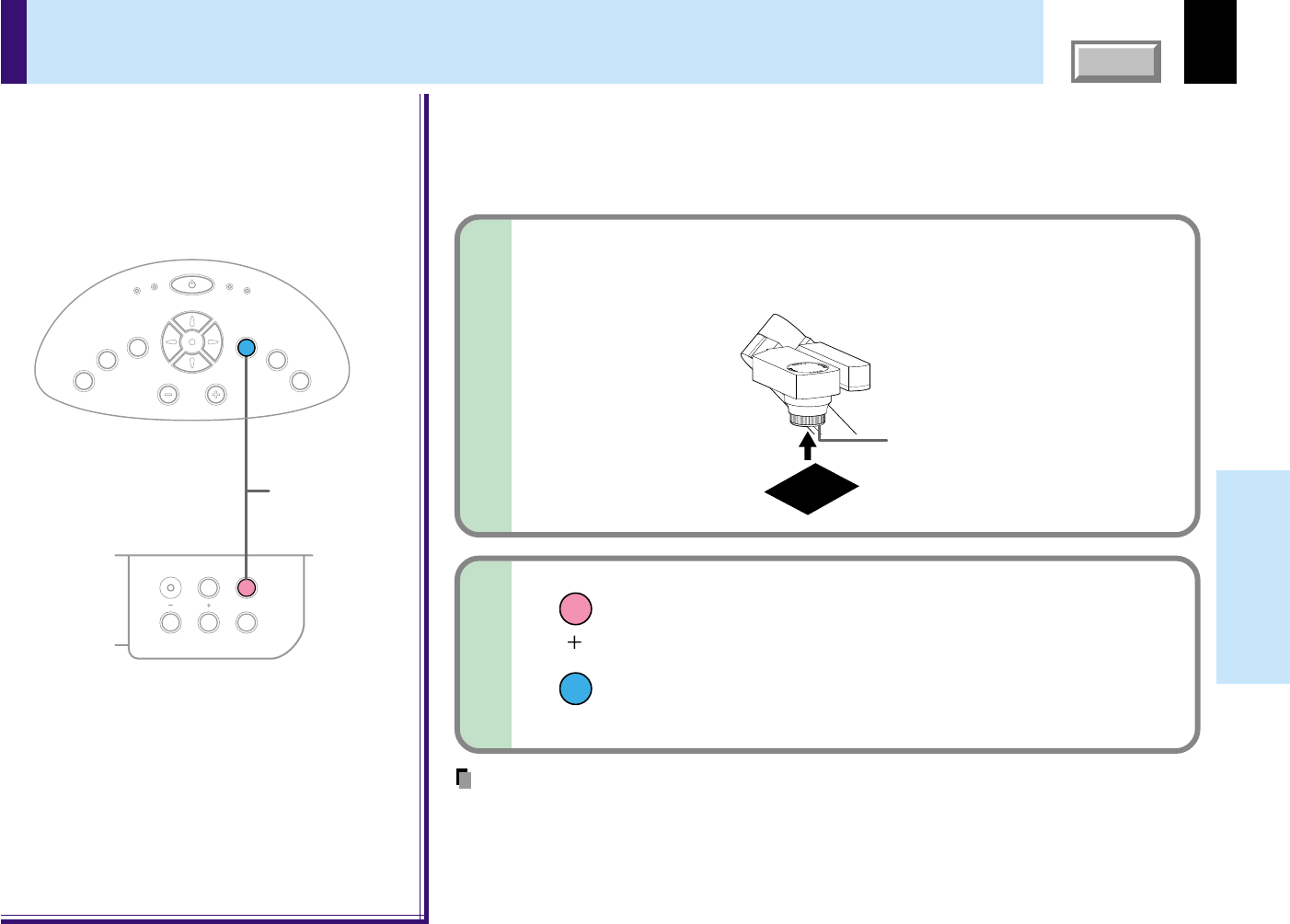
Point the remote control at the infrared remote sensor and press a button.
Notes
•The remote control may not operate when there is sunlight or other strong light such as a fluorescent lamp shining on the projector’s remote sensor.
•Operate the remote control from a position where the remote sensor is visible.
•Do not drop the remote control or otherwise jolt it.
•Keep the remote control out of locations with excessively high temperature or humidity.
•Do not get water on the remote control or place wet objects on it.
•Do not disassemble the remote control.
•Under unusual circumstances the remote control may not operate well due to the location being used or the surroundings.
At such times, change the direction of the remote control to the projector and retry the operation.
Front side
Rear side
About
15
°
About
15
°
About
15
°
About
15
°
About
5m
About
15
°
About
15
°
About
15
°
About
15
°
About
5m
INPUT
ENTER
CT-90072
SET
EXIT
PIP
MUTE
CALL
RESIZE
MENU
INPUT
ENTER
CT-90072
SET
EXIT
PIP
MUTE
CALL
RESIZE
MENU
17
Installation and
connections
CONTENTS
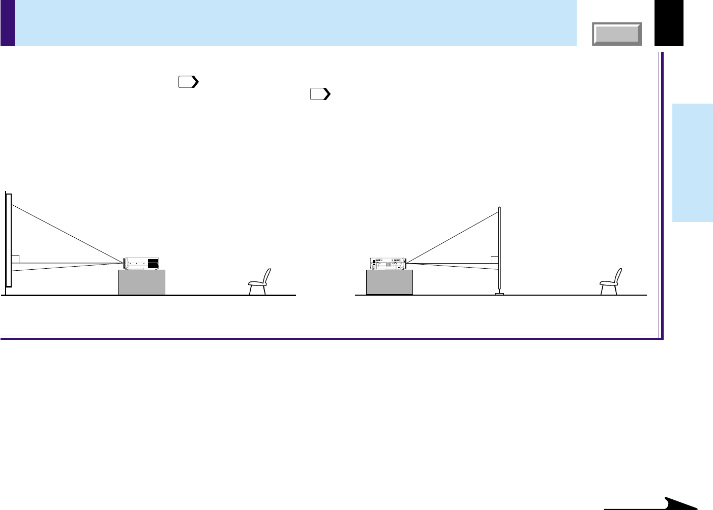
Floor-mounted projector placement
Floor-mounted front projection
Viewing a picture projected on the front of the
screen from a floor installation.
Floor-mounted rear projection
Viewing a picture projected through the back of the
screen from a floor installation.
Viewer
Translucent screen
Viewer
There are two ways to place the floor-mounted projector.
When the projector is mounted in the rear projection mode, the picture is reversed. Set the “Projection mode” (on the menu screen)
according to the projection method.
50
At shipping from factory, it is set for the Floor-mounted front projection.
For the ceiling-mounted projector placement, refer to the page
22
.
USB
S-VIDEOVIDEO
AUDIO
COMPUTER
(
Y/P
B
/P
R
)
CONTROL
Continued
18
Installation and
connections
CONTENTS
Place the projector on a steady, level surface such as a table.
To obtain proper screen projection, place the projector so that the light beam hits the screen squarely.
Floor-mounted projector placement (continued)
Top view
Screen
Screen
a
90°
Side view
90°
Screen
Projection size
(inches)
30
36
50
80
100
120
150
180
Minimum
(At maximum zoom)
–
0.70
0.98
1.59
2.00
2.41
3.02
3.63
Maximum
(At minimum zoom)
0.70
0.85
1.19
1.92
2.41
2.89
3.63
–
a (m)
• The values are approximations.
1
2
90°
K
E
Y
S
T
O
N
E
A
U
T
O
S
E
T
E
X
I
T
ON / STANDBY
VOL / ADJ
E
N
T
E
R
M
E
N
U
I
N
P
U
T
F
A
N
T
E
M
P
L
A
M
P
O
N
Point the lens straight at the center of the screen as above.
Determine the screen size projected on the screen.
The projection size depends on the distance between the lens and the screen.
Adjust the projection size by changing the distances as shown below.
Place the projector horizontally so that the projecting light hits the
screen squarely.
Continued
a: Distance between the lens and the screen (m)
Limit: 0.70m < a < 3.63m
a (min.) =
Projection size x 20.32 - 31
1000
a (max.) =
Projection size x 24.38 - 32
1000
Note
You can adjust the vertical projection position with the lens shift dial.
20
19
Installation and
connections
CONTENTS
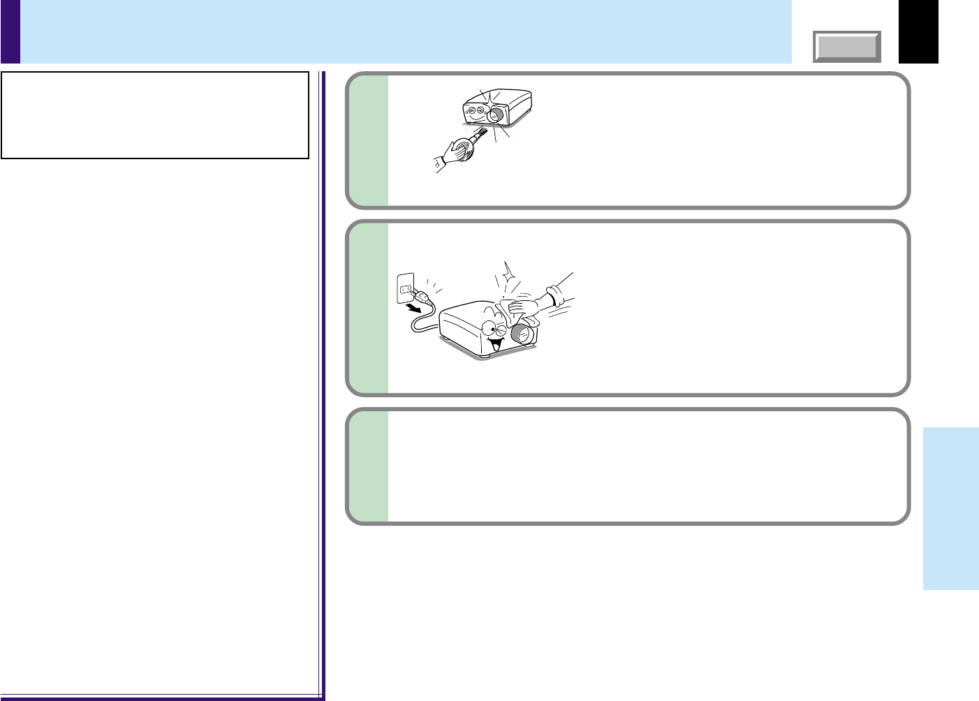
Connect the power cord.
• Insert one end into the AC IN socket on the projector.
• Insert the other end into a wall outlet.
Notes
•When the projector is moved from a cold location to a warm location, or when the ambient temperature in the projection room has risen suddenly,
moisture may condense on the lens or the internal optical section to blur the projected pictures. In such a case, leave the projector for an adequate time
(1 to 2 hours, depending on the room’s condition) before using it, so it adjusts to the ambient temperature.
•If the screen is exposed to direct sunlight or other strong light, the projected picture will become too faint to see. Shut out the light with curtains or by
other means.
•If the screen and the projector are not installed properly, the projected picture may be distorted.
3
4
Floor-mounted projector placement (continued)
Light (Orange)
ON / STANDBY
F
A
N
T
E
M
P
L
A
M
P
O
N
Take off the lens cover.
Power cord (Supplied)
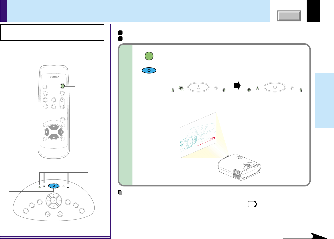
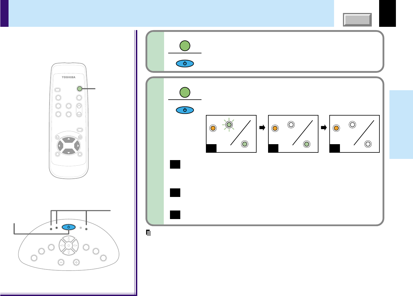
The three indicators, TEMP, LAMP, and ON, light in green
for several seconds and then the ON indicator lights in
orange and the projector turns to the standby mode.
Do not perform any operations while the three indicators
are lit green.
20
Installation and
connections
CONTENTS
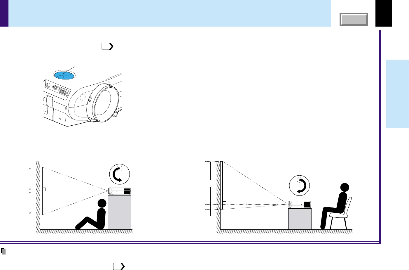
Lens shift function
When turning the lens shift dial, the lens moves to upward or downward and the projection position on the screen is to be adjusted.
At shipping from factory, it is set to the state turned clockwise fully (the highest projection position).
Refer to “Projection on the screen”
27
, and adjust it after projecting a picture.
90°
50%
50%
90°
10%
90%
When the lens shift dial is turned counterclockwise
fully, the projection position becomes the lowest.
When the lens shift dial is turned clockwise fully, the
projection position becomes the highest.
At shipping from factory, the lens shift dial is set to
this state.
Lens shift dial
Notes
•Never give strong force to the lens shift dial as this may cause malfunction.
•At the ceiling-mounted projector placement
22
, the relation between the moving direction of the projection position and the turning direction of the lens
shift dial becomes contrary from the case of the floor-mounted projector placement.
The tilt of the projector can be adjusted using the foot adjuster. Adjust this when the highest position by the lens shift dial
20
is
insufficient. Refer to “Projection on the screen”
27
, and adjust the foot adjuster after projecting a picture.
Lift the front of the projector until the desired tilt
angle is obtained and hold down the foot adjuster
release button.
The foot adjuster will extend.
Release the button to lock in position.
1
Turn the foot adjuster to make fine adjustment to
the height.
Turn clockwise to lift up.
Turn counterclockwise to lower.
2
Notes
•To put the foot adjuster back, hold down the foot adjuster release button and lower the front slowly.
•Be sure to hold the projector when putting the foot adjuster back so as not to let the front fall on your fingers.
•Do not tilt the projector at an angle exceeding the range adjustable by the foot adjusters, since the life duration of the lamp may be shortened.
Lift up
Lower
22
Installation and
connections
CONTENTS
Ceiling-mounted front projection
Viewing a picture projected on the front of the screen from a
ceiling installation.
Ceiling-mounted rear projection
Viewing a picture projected through the back of the screen from a
ceiling installation.
Perform the “Projection mode” setting on the menu screen for the projection method.
50
Note
The relation between the projection size and the distance to the screen is the same as that of the floor-mounted projection mode
18
.
Translucent screen
Viewer
Ceiling-mounted projector placement
CAUTION
When a ceiling mount is required, please consult with the dealer.
Viewer
USB
S-VIDEOVIDEO
AUDIO
COMPUTER
(
Y/P
B
/P
R
)
CONTROL
23
Installation and
connections
CONTENTS
Notes
•The projector cannot be connected to a computer without an analog RGB connector. For details, refer to the computer manual.
•You may not be able to connect some computers to the projector. For details, consult the dealer.
•When connecting to a Macintosh computer, some models may need a Mac adapter for connection.
•Some computers may have output modes which are not compatible with this projector. Check the compatibility of the connectors, signal levels, timing,
resolutions, etc.
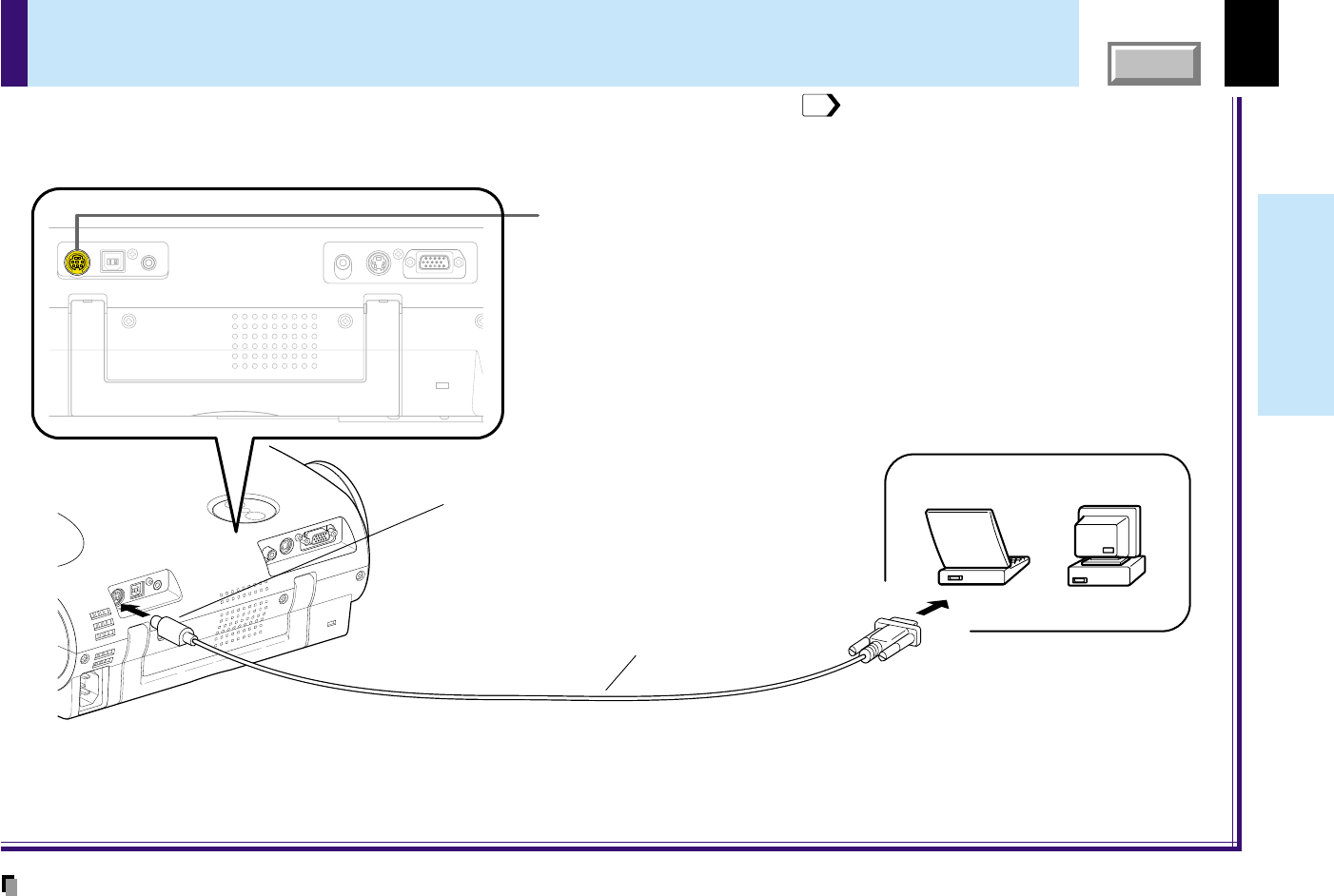
Connecting a computer
You can project the picture from the computer.
Check that the power supplies for the projector and for the computer are off before connecting the cables.
COMPUTER connector
For use as both analog RGB and Y/P
B/PR input. At shipping from factory, it is
set for use as analog RGB input.
AUDIO jack
For use as audio signal of all input sources.
RGB cable (supplied)
To AUDIO jack
Computer
To COMPUTER connector
Be sure to connect in the proper
direction.
To monitor port
Audio cable (supplied)
ø3.5mm stereo mini-jack
To audio output port
USBS-VIDEOVIDEOAUDIO
COMPUTER
(
Y/P
B
/P
R
)
CONTROL
24
Installation and
connections
CONTENTS
Connecting video equipment
Note
The S-VIDEO connector and VIDEO jack can be used independently, but the audio input jack is used for all input sources.
You can project the picture from video equipment.
Check that the power supplies for the projector and for the video equipment are off before connecting the cables.
Pin plug (red)
To audio output (R)
(Yellow) To VIDEO jack
To S-VIDEO connector
Be sure to connect in the proper
direction.
To S-video output
Audio cable
(supplied)
Pin plug (white)
To audio output (L)
Pin plug (yellow)
To video output
To AUDIO jack
S-video cable
(not supplied)
Video cable
(supplied)
Video equipment
AUDIO jack
For use as audio signal of all input sources.
S-VIDEO connector
VIDEO jack
USBS-VIDEOVIDEOAUDIO
COMPUTER
(
Y/P
B
/P
R
)
CONTROL
Continued
25
Installation and
connections
CONTENTS
Connecting video equipment (continued)
You can project the picture from video equipment with component video output jack.
Check that the power supplies for the projector and for the video equipment are off before connecting the cables.
COMPUTER connector
For use as both analog RGB and Y/P
B
/P
R
input. At shipping from factory, it is
set for use as analog RGB input.
Change the setting on the menu screen when using as Y/P
B
/P
R
input.
AUDIO jack
For use as audio signal of all input sources.
To COMPUTER connector
Be sure to connect in the proper
direction.
Pin plug (red)
To audio output (R)
Monitor cable
Mini D-sub 15P-BNC
(Not supplied)
Pin plug (white)
To audio output (L)
(Blue) To P
B
video output
(Green) To Y video output
(Red) To P
R
video output
Adapter
BNC-pin
(Not supplied)
To AUDIO jack
Audio cable (supplied)
Video equipment
(DVD player, etc.)
USBS-VIDEOVIDEOAUDIO
COMPUTER
(
Y/P
B
/P
R
)
CONTROL
44
26
Installation and
connections
CONTENTS
Projector operation control by a computer
CONTROL connector
Computer
To RS-232C port
Control cable (supplied)
To CONTROL connector
Be sure to connect in the proper
direction.
USBS-VIDEOVIDEOAUDIO
COMPUTER
(
Y/P
B
/P
R
)
CONTROL
You can control the projector by a computer connected with the control cable supplied.
71
Check that the power supplies for the projector and for the computer are off before connecting the cables.
Note
Do not connect any cable other than the exclusive one supplied.
27
Operations
CONTENTS
Preparation
1
Install and connect the projector properly.
2
Take off the lens cover.
Press ON/STANDBY.
The projector turns on and the ON, LAMP and FAN indicators
light in green.
(The LAMP indicator blinks while the lamp is warming up.)
The lamp lights and the start up display appears.
CAUTION – Do not look into the projection
lens while operating the projector.
Projection on the screen
ON / STANDBY
F
A
N
T
E
M
P
L
A
M
P
O
N
ON / STANDBY
F
A
N
T
E
M
P
L
A
M
P
O
N
(Green)(Green)(Green)(Green)(Green)(Green
Flashing)
1
Continued
MENU
ON /
INPUT
ENTER
CT-90106
KEYSTONEAUTO SET
EXIT /
P.MODE
PIP
FREEZE
MUTE
CALL
RESIZE
VOL
/
ADJ
STANDBY
1
1
1
K
E
Y
S
T
O
N
E
A
U
T
O
S
E
T
E
X
I
T
ON / STANDBY
VOL / ADJ
E
N
T
E
R
M
E
N
U
I
N
P
U
T
F
A
N
T
E
M
P
L
A
M
P
O
N
Indicators
Remote control
Control panel
(Main unit side)
ON/STANDBY
ON/STANDBY
Notes
•The startup screen disappears when you push the EXIT button or wait for a while. You can also
set the startup screen not to be displayed on the menu screen.
50
•When a projector is used for the first time, the language selection menu is displayed after the
startup screen disappears. Set it up with procedures 2 and 3 on the next page.
28
Operations
CONTENTS
Projection on the screen (continued)
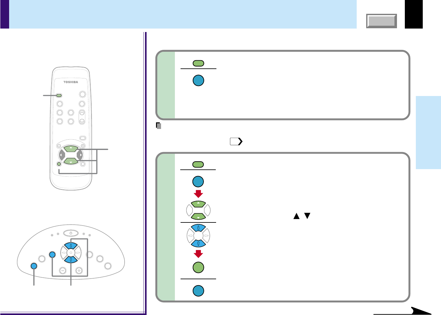
Press ENTER to confirm.
Press EXIT to return to step 2 if you want to re-select a
language.
3
Continued
MENU
ON /
INPUT
ENTER
CT-90106
KEYSTONEAUTO SET
EXIT /
P.MODE
PIP
FREEZE
MUTE
CALL
RESIZE
VOL
/
ADJ
STANDBY
K
E
Y
S
T
O
N
E
A
U
T
O
S
E
T
E
X
I
T
ON / STANDBY
VOL / ADJ
E
N
T
E
R
M
E
N
U
I
N
P
U
T
F
A
N
T
E
M
P
L
A
M
P
O
N
2
2,3
22,3
ENTER
ENTER
Remote control
Control panel
(Main unit side)
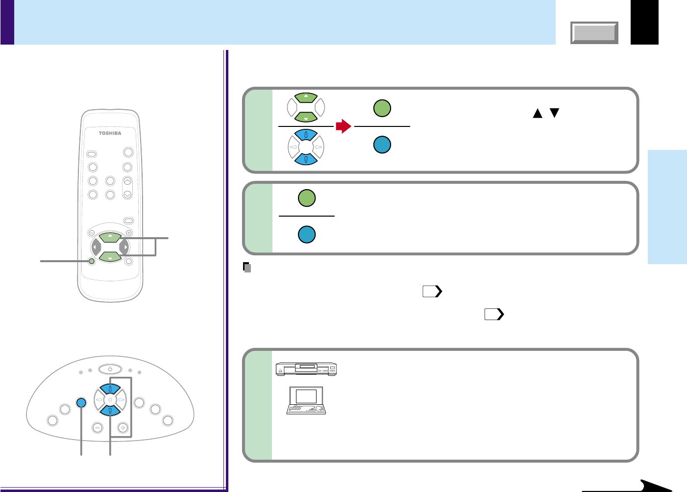
Select a desired language with the
selection buttons (
/
), and
press ENTER.
A menu confirming the selection result is
displayed in the selected language.
2
ENTER
ENTER
When a projector is used for the first time, the language selection menu, which is to select a
language for displaying menus or messages, is displayed. Select a desired language. (At
shipping from factory, it is set to English.)
Notes
•The language selection menu will not be displayed on the second and subsequent times you
turn on the power. However, if “Reset all”
51
is executed, the language selection menu will
be displayed when the power is turned on next.
•The language can also be selected on the menu screen.
49
•This Owner’s manual is described on the supposition that English was selected.
4
Turn on the connected equipment and put it in
playback mode.
Select “Cancel” or install driver contained in the supplied
CD-ROM, when the dialog box of the Add New Hardware
Wizard screen appears on the computer when connecting a
computer. (The supplied CD-ROM contains a driver information
file named TOSHIBA_TLP.inf. Click the Browse button of the
dialog box to find and designate this file.)
29
Operations
CONTENTS
Select the input source by pressing INPUT
repeatedly.
At shipping from factory, “Analog RGB” connected to
COMPUTER connector or “Video” connected to VIDEO Jack
can be selected. (You can select “Camera” when using the
model with a document imaging camera.)
The icon and the name of the selected input source appear on
the screen.
Projection on the screen (continued)
5-a
5-b
MENU
ON /
INPUT
ENTER
CT-90106
KEYSTONEAUTO SET
EXIT /
P.MODE
PIP
FREEZE
MUTE
CALL
RESIZE
VOL
/
ADJ
STANDBY
5-a,5-b
5-b
5-a,5-b5-b
K
E
Y
S
T
O
N
E
A
U
T
O
S
E
T
E
X
I
T
ON / STANDBY
VOL / ADJ
E
N
T
E
R
M
E
N
U
I
N
P
U
T
F
A
N
T
E
M
P
L
A
M
P
O
N
INPUT
INPUT
INPUT
INPUT
ENTER
ENTER
Remote control
Control panel
(Main unit side)
Select the input source to project.
There are two kinds of methods as follows (5-a and 5-b.)
Note
The types of input sources selected when the INPUT button is pressed repeatedly can be
set from the menu screen.
44
Continued
Press INPUT and hold for two seconds.
The input source selection menu appears.
Select the input source to project with the
selection buttons (
/
).
Regardless of the contents of input source settings on the
menu screen, all the input sources are displayed here for
selection.
Press ENTER.
A picture of the selected input source is projected.
When a sound signal source is also connected, sound is
emitted from the speaker.
30
Operations
CONTENTS
Projection on the screen (continued)
76
Notes
(Signal sent from the computer)
•If you project an image from a computer with an LCD screen while monitoring the image on
the computer, the image may not be projected properly, depending on the computer model.
In this case, turn off the computer display. For details on controlling the computer display, etc.,
refer to the computer’s manual and description on the software for the computer used.
•The TLP550/TLP551 projects an image by XGA signal (1024 x 768) in full screen. The image
quality from a computer signal other than XGA may be inferior. It is recommended to set the
external monitor connected to the computer to XGA mode (1024 x 768).
•The TLP250/TLP251 projects an image by SVGA signal (800 x 600) in full screen. The image
quality of a computer signal except SVGA may deteriorate. It is recommended to set the
external monitor connected to the computer to SVGA mode (800 x 600).
•The projector can be also applied to DDC2B (Display Data Channel 2B). If your computer is
applied to the DDC, start up your computer after turning on the projector. If the order is
reversed, the computer may not output any signal.
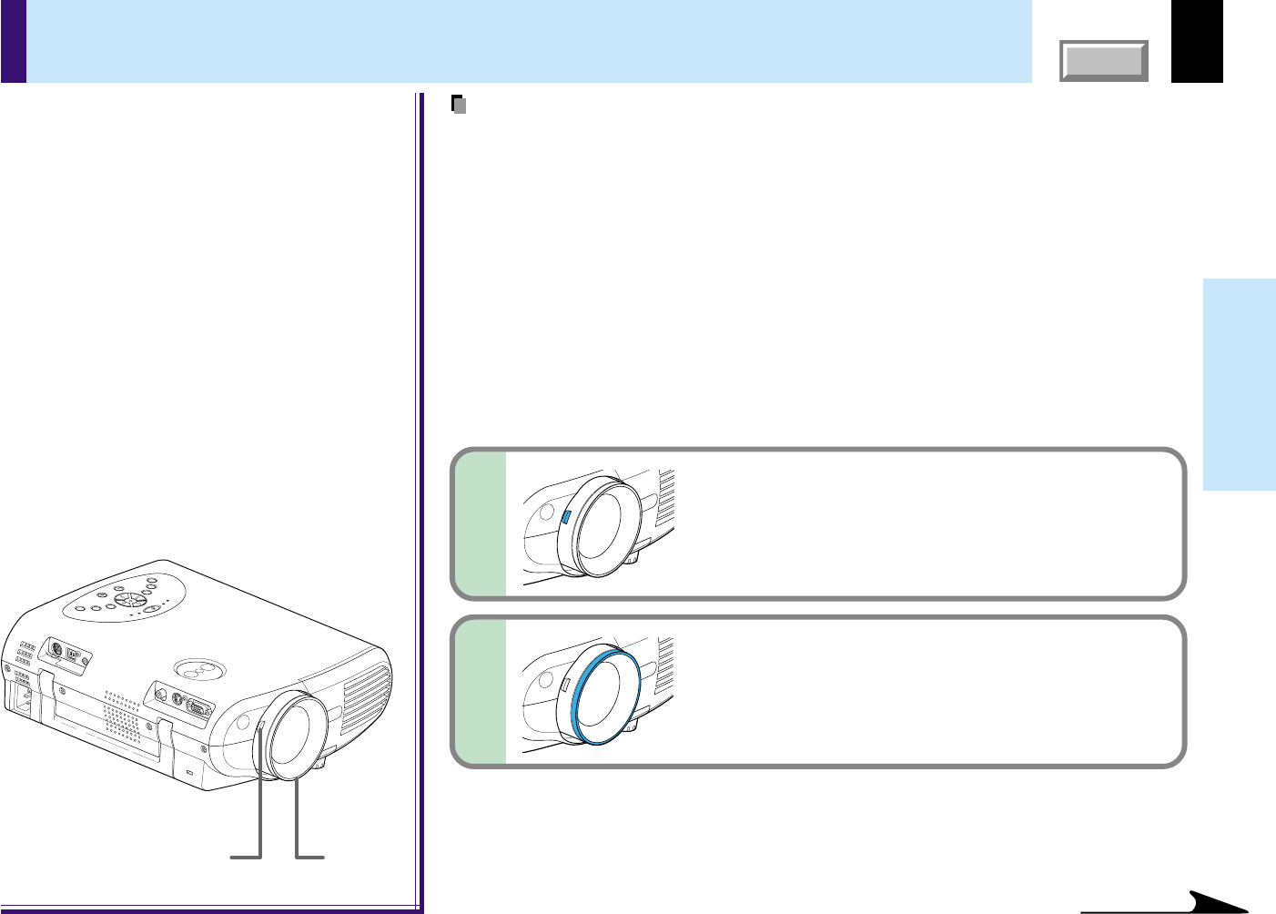
Adjust the picture size by turning the
zooming lever.
Turn to the right to enlarge the picture.
Turn to the left to reduce the picture.
Focus on the picture by turning the
focusing ring.
A still picture is recommended for focusing.
6
7
Continued
31
Operations
CONTENTS
Notes
•To change the projecting angle, adjust the foot adjuster.
21
•If the screen image suffers keystone distortion, press the KEYSTONE button to adjust the
distortion.
34
•Due to lamp characteristics, flickers may occasionally occur in a picture. This is not
malfunction of the unit.
•The lamp may rarely burst with a loud sound.
•The projector’s liquid crystal panel is made using extremely advanced technology, but there
may be black spots (pixels that do not light) or bright spots (pixels that are constantly lit) on the
panel. Please note that these are not malfunctions.
•When trying to press a button whose operation is not available, the
icon appears.
•When supplying the signal not compatible with the projector, the
icon appears.
•When signals are not input from the input source, the
icon appears.
•The projector may stop operating if the surrounding temperature is too high or if the air filter is
clogged with dust.
60
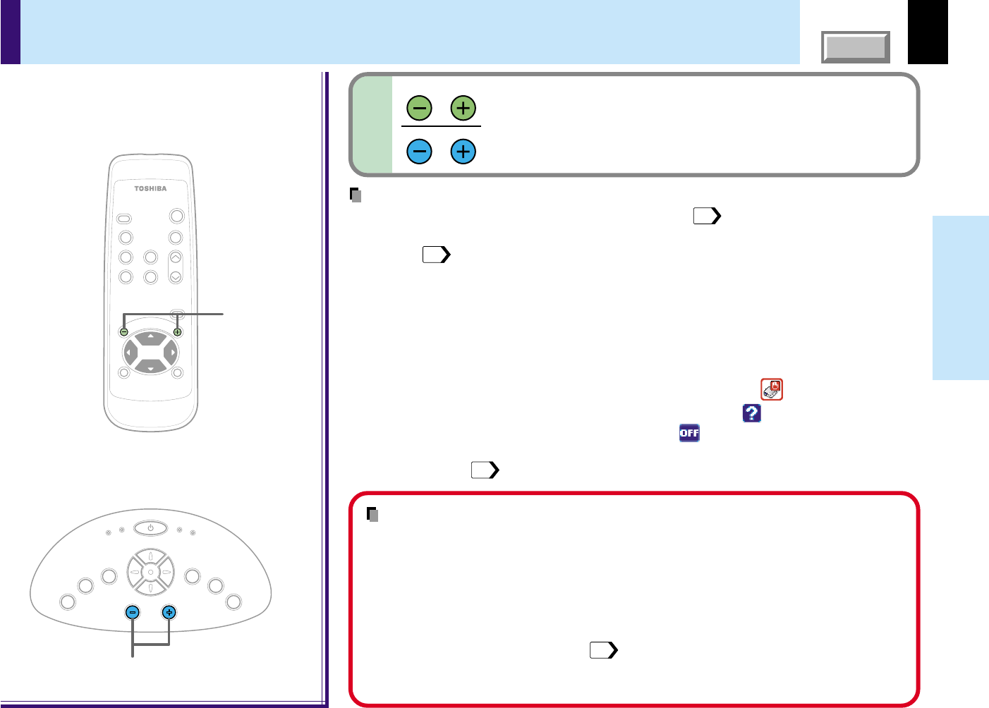
Press VOL/ADJ (+/
-
) to adjust volume.
Press the (+) button to increase volume.
Press the (
-
) button to decrease volume.
8
VOL/ADJ
VOL/ADJ
Projection on the screen (continued)
MENU
ON /
INPUT
ENTER
CT-90106
KEYSTONEAUTO SET
EXIT /
P.MODE
PIP
FREEZE
MUTE
CALL
RESIZE
VOL / ADJ
STANDBY
K
E
Y
S
T
O
N
E
A
U
T
O
S
E
T
E
X
I
T
ON / STANDBY
VOL / ADJ
E
N
T
E
R
M
E
N
U
I
N
P
U
T
F
A
N
T
E
M
P
L
A
M
P
O
N
8
8
Remote control
Control panel
(Main unit side)
About the LCD Panel
The life of the LCD panel is limited.
Take care over the points below so as to use the panel for years.
•To prolong the life of this panel, never fail to turn the power off when the panel is not in use
and make sure that the lamp has gone out. The state of the lamp being extinguished helps
enhance the effect of energy saving.
•If the air filter is stained and is clogged up, the main unit inner temperature rises. As a
result, the life of the LCD is shortened and a malfunction may also occur.
Clean the air filter from time to time
61
and replace it regularly. It is recommended that
this replacement be done at the time of replacing a lamp. (Ask a dealer where the unit was
purchased or your nearby service station about an air filter for replacement.)
32
Operations
CONTENTS
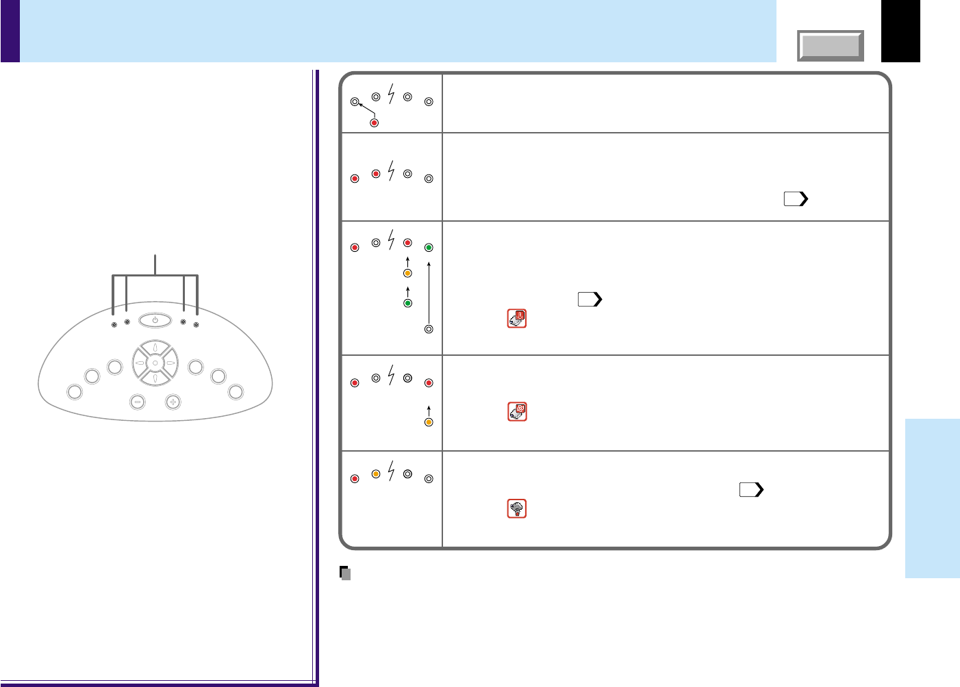
Turning the power off
Press ON/STANDBY after using the projector.
An instruction message for turning the power off appears on
the screen and disappears after a while. When the message
disappears, operation becomes invalid.
Press ON/STANDBY again.
Cooling starts. Once cooling is completed, the LAMP and FAN
indicators turn off and the standby mode is set. (The ON
indicator turns in orange.)
To protect the light source lamp, the LAMP indicator blinks as long as
a minimum of cooling is necessary. The power cannot be turned back
on during this time. Unplugging the power cord at this time will shorten
the lamp’s duration life.
The cooling fan continues to run for a while to expel the heat remaining
inside. If you are in a hurry, however, you may unplug the power cord
at this time.
The standby mode is set.
1
2
MENU
ON /
INPUT
ENTER
CT-90106
KEYSTONEAUTO SET
EXIT /
P.MODE
PIP
FREEZE
MUTE
CALL
RESIZE
VOL
/
ADJ
STANDBY
2
1,2
1,2
K
E
Y
S
T
O
N
E
A
U
T
O
S
E
T
E
X
I
T
ON / STANDBY
VOL / ADJ
E
N
T
E
R
M
E
N
U
I
N
P
U
T
F
A
N
T
E
M
P
L
A
M
P
O
N
(Green)
(Green)(Green)
(Off)
(Off)(Off)
Flashing
(Orange)(Orange)
ABC
ON
LAMP
FAN
ON
LAMP
FAN
ON
LAMP
FAN
(Orange)
ON/STANDBY
ON/STANDBY
ON/STANDBY
ON/STANDBY
B
C
A
Notes
•The projector consumes about 15W of power in the standby mode. We recommend you
unplug the power cord when not using the projector for long periods of time.
•Be sure that the LAMP indicator has turned off before unplugging the power cord. Cutting the
power by unplugging the power cord while the projector is operating or the light source lamp is
being cooled will shorten the lamp’s duration life. Should a fault or some other irregularity
arise with this unit, unplug the power cord.
•When reinserting the power plug before the lamp has cooled, please wait until the lamp has
cooled sufficiently before use. When the lamp is at a high temperature, it may not light and it’s
life duration will be shortened.
Remote control
Control panel
(Main unit side)
Indicators
33
Operations
CONTENTS
Notes
•Automatic adjustment may not be performed properly for signals other than those computers’
signals with which the projector is compatible.
•The horizontal position, vertical position, sampling phase and sampling frequency can also be
adjusted from the menu screen
46
.
*Sampling frequency
Analog RGB signals input from the computer are converted into digital signals inside the
projector. The sampling frequency is the number of times per second the analog signals are
converted into digital signals. In order to capture (sample) each individual dot of the
computer’s signals, the sampling frequency must be adjusted to match the computer’s dot
clock frequency. If this adjustment is off, details of the image details may be blurred, a striped
pattern may appear if images with many vertical lines are displayed, or the image’s width may
change. For computer signals with which are projector-compatible, the sampling frequency is
adjusted automatically even when the AUTO SET button is not pressed.
*Sampling phase
The sampling phase is the timing at which the computer’s analog RGB signals are sampled. If
the sampling phase is off, the individual dots cannot be sampled at the proper timing, resulting
in blurred or flickering images.
Adjusting the picture automatically
1
2
MENU
ON /
INPUT
ENTER
CT-90106
KEYSTONE
AUTO SET
EXIT /
P.MODE
PIP
FREEZE
MUTE
CALL
RESIZE
VOL
/
ADJ
STANDBY
K
E
Y
S
T
O
N
E
A
U
T
O
S
E
T
E
X
I
T
ON / STANDBY
VOL / ADJ
E
N
T
E
R
M
E
N
U
I
N
P
U
T
F
A
N
T
E
M
P
L
A
M
P
O
N
2
2
You can adjust the optimum horizontal position, vertical position, sampling phase and
sampling frequency for projecting analog RGB signals at the touch of a button.
AUTO SET
AUTO SET
Input full screen video signals from the input
source (computer) and project the image.
Adjustments may not be performed properly for images that are
not displayed on the entire screen or for extremely dark
images.
Press AUTO SET.
The horizontal position, vertical position, sampling phase and
sampling frequency are adjusted automatically.
The icon
appears during signal processing.
Remote control
Control panel
(Main unit side)
34
Operations
CONTENTS
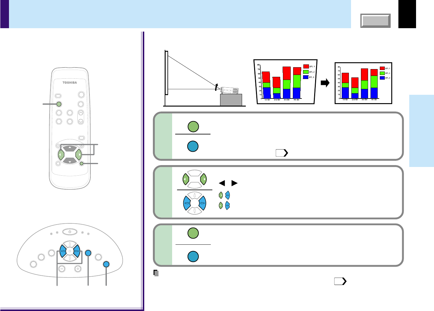
Correcting the keystone distortion
A picture may be expanded on the upper side if projected upward from the projector lifted
up by the foot adjuster. The projector can correct this keystone distortion.
MENU
ON /
INPUT
ENTER
CT-90106
KEYSTONEAUTO SET
EXIT /
P.MODE
PIP
FREEZE
MUTE
CALL
RESIZE
VOL / ADJ
STANDBY
K
E
Y
S
T
O
N
E
A
U
T
O
S
E
T
E
X
I
T
ON / STANDBY
VOL / ADJ
E
N
T
E
R
M
E
N
U
I
N
P
U
T
F
A
N
T
E
M
P
L
A
M
P
O
N
12
1
3
2
3
Remote control
Control panel
(Main unit side)
1
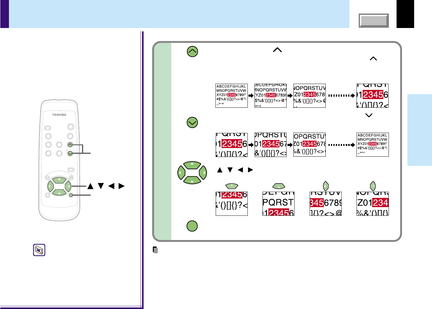
Press KEYSTONE.
The keystone adjustment menu appears.
(This menu is the same as the sub-menu which is displayed
when “Correct the keystone distortion of the screen” is selected
from GUIDE MENU.
44
)
Adjust the distortion with the selection buttons
(
/
).
: The upper part of the screen shrinks.
: The upper part of the screen expands.
KEYSTONE
KEYSTONE
2
3
To finish the adjustment, press EXIT repeatedly
until the menu disappears.
EXIT
EXIT
Before correction
After correction
Notes
•Turn the lens shift dial clockwise fully before using the foot adjuster.
20
•Due to digital correction processing, some of the information may dropped or the picture
quality may be degraded depending on the keystone correction setting or the contents of the
signal source.
35
Operations
CONTENTS
Cutting off the picture and sound temporarily
The image and sound of this projector can be turned off if you wish to temporarily project
the image from another projector or an OHP, etc., onto the screen.
Note
The mute mode is cancelled if another operation is performed during the mute mode.
MENU
ON /
INPUT
ENTER
CT-90106
KEYSTONEAUTO SET
EXIT /
P.MODE
PIP
FREEZEMUTE
CALL
RESIZE
VOL
/
ADJ
STANDBY
MUTE
MUTE
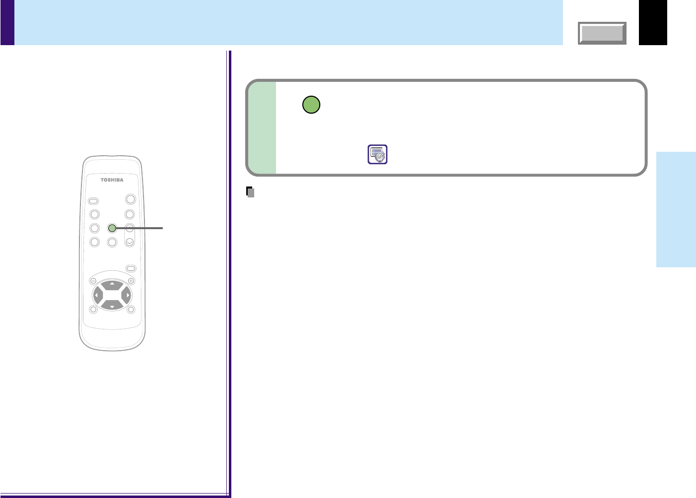
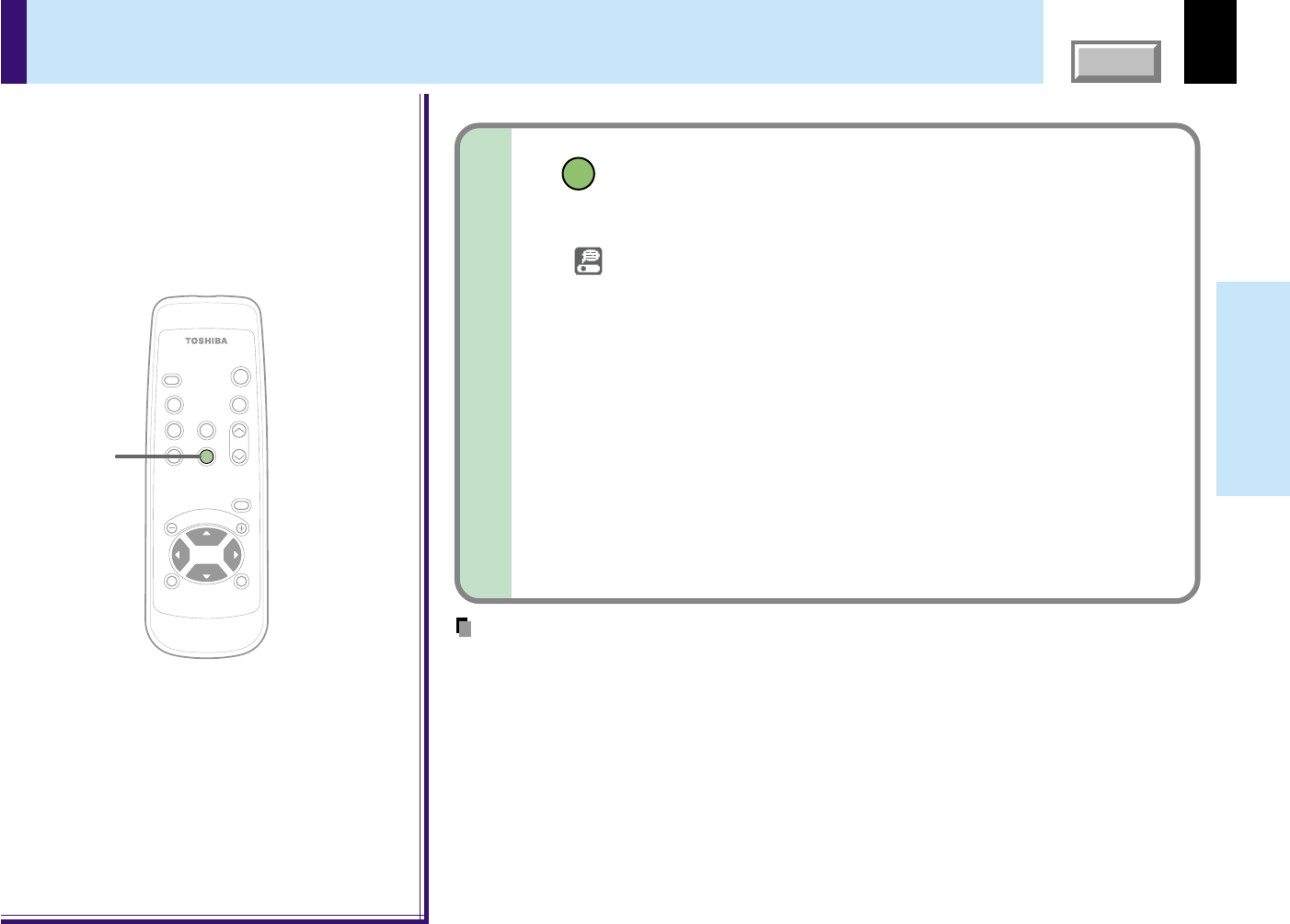
Press MUTE.
The sound and picture are cut off temporarily.
To cancel the mute mode, press MUTE again. The image and
sound will be output.
The
icon appears in the mute mode.
Remote control
36
Operations
CONTENTS
Freezing the picture
You can freeze the image being projected.
Use this function to stop moving images from a video recorder during presentations.
Notes
•The frozen image can be enlarged with the RESIZE buttons. The freeze mode is cancelled if
any operation other than RESIZE is performed.
•The freeze mode cannot be set when there is no input (when no signals are being supplied
from a signal source).
•The input source’s moving image continues to run even when the projector is set in freeze
mode.
MENU
ON /
INPUT
ENTER
CT-90106
KEYSTONEAUTO SET
EXIT /
P.MODE
PIP
FREEZEMUTE
CALL
RESIZE
VOL
/
ADJ
STANDBY
FREEZE
FREEZE
Press FREEZE.
The picture freezes.
To release the picture, press FREEZE again.
The
icon appears in the freeze mode.
Remote control
37
Operations
CONTENTS
You can enlarge (resize) the picture size projected.
Enlarging the picture size
Press RESIZE ().
The enlargement ratio increases each time the RESIZE ()
button is pressed.
The enlargement ratio can be increased continuously by keeping the
button pressed in.
To reduce the enlargement ratio, press the RESIZE () button.
The enlargement ratio can be reduced continuously by keeping the button
pressed in.
The enlarged section is moved when the selection buttons
( / / / ) are pressed.
The section can be moved continuously by keeping the button pressed in.
Press the EXIT button to cancel the resize mode and return to the
original size.
MENU
ON /
INPUT
ENTER
CT-90106
KEYSTONEAUTO SET
EXIT
/
P.MODE
PIP
FREEZE
MUTE
CALL
RESIZE
VOL
/
ADJ
STANDBY
EXIT
RESIZE
///
RESIZE
RESIZE
EXIT
Notes
•Enlarged images can be frozen by pressing the FREEZE button. The frozen image can also be
enlarged or reduced.
•The resize mode is cancelled if any operation other than setting the freeze mode is performed.
•This projector uses electrical digital resizing, so the picture quality degrades when images are
enlarged.
•In rare cases, the picture may be disturbed while the magnification section is being moved.
•This function does not work in no input status (no signal is supplied from the signal source).
Remote control
The icon
appears in the resize mode.
38
Operations
CONTENTS
Press PIP.
A sub-picture is displayed.
Press the PIP button again to turn off the sub-picture.
Video or S-video images can be displayed as small images within the computer’s image.
(Referred to as “sub-pictures” in this manual.)
Notes
•The PIP function cannot be used when a source other than an RGB input source is selected.
•The PIP function cannot be used without signals supplied from an RGB signal source.
•The sub-picture turns off if any other operation is performed.
•The signal source, size and display position to display sub-pictures can be changed from the
menu screen.
52
PIP
Displaying PIP Sub-pictures
MENU
ON /
INPUT
ENTER
CT-90106
KEYSTONEAUTO SET
EXIT /
P.MODE
PIP
FREEZE
MUTE
CALL
RESIZE
VOL
/
ADJ
STANDBY
PIP
Remote control
39
Operations
CONTENTS
CALL
Notes
•The information displayed is not refreshed even if it changes. To refresh the information, turn
off the information display, then turn it back on.
•The information display turns off if any other operation is performed.
•The “Lamp time” shows an approximate time for lamp replacement. (It should not be used as a
lamp warranty time counter.) If the time indicated here nears 1500, contact your store of
purchase about obtaining a replacement lamp (TLPL55, sold separately).
•The “Lamp time” can be reset when the lamp is replaced.
•The “Version” is the version of the control program used in the projector and is used for
servicing, etc.
MENU
ON /
INPUT
ENTER
CT-90106
KEYSTONEAUTO SET
EXIT /
P.MODE
PIP
FREEZE
MUTE
CALL
RESIZE
VOL
/
ADJ
STANDBY
CALL
Displaying Information
Information on the input signal source, etc., can be displayed.
Remote control
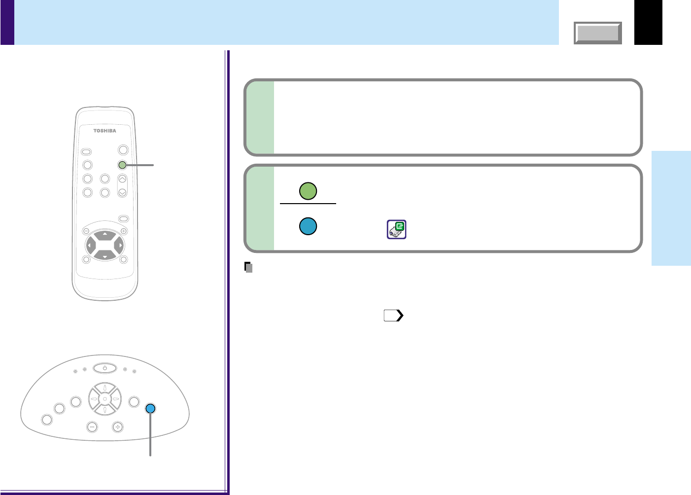
Press CALL.
The information described below is displayed.
The information display turns off when the CALL button is
pressed again.
Status display
Input- current input source
H-resolution- the horizontal resolution of the input signal (at RGB input)
V-resolution- the vertical resolution of the input signal (at RGB input)
H-frequency- the horizontal frequency of the input signal (at RGB input)
V-frequency- the vertical frequency of the input signal (at RGB input)
Sync- the polarity of the sync signal (at RGB input)
Video mode- the color mode of the video signal (at Video, S-Video input)
Signal format- the formatting of the Y/P
B/PR signal (at Y/PB/PR input)
Lamp time- the elapsed usage time of the lamp
Version- the version of the firmware
Shutter- the shutter speed of the document imaging camera (at
document imaging camera input)
40
Operations
CONTENTS
Operating the presentation mode
Notes
•This function is available with O.S (operating system) of Windows 98/98SE, Windows Me, Windows 2000 or Mac OS9 with a USB port as standard.
•When connecting to the computer’s USB port for the first time, a message asking you to insert the Windows98 or Windows 98SE CD-ROM may appear
on the computer’s monitor screen, depending on whether or not the device driver is installed. If so, do as the message says.
•When using a USB cable other than the supplied one, be sure to use a shielded type.
You can change the slide, for the presentation on the computer, by using the remote control when connecting the projector to the computer with
the supplied USB cable.
To USB connector
Be sure to connect in the proper direction.
USB cable (supplied)
Computer for presentation
To USB port
USB connector
USBAUDIO
CONTROL
1
Connect a computer to the projector with the supplied USB cable.
Also connect the RGB cable and the audio cable if necessary.
23
2
Start a presentation on the computer.
•In case of Microsoft
®
PowerPoint
®
, start the slide show to make a state of displaying the first slide.
•In case of Adobe
®
Acrobat
®
or AcrobatReader
®
, make state that [Full Screen] is selected from [View] menu.
•This function is also available in other application software that can change a slide by pressing
, of a
computer.
Continued
41
Operations
CONTENTS
Operating the presentation mode (continued)
Adjust the projector before presentation if
necessary.
In the presentation mode after step 5, the projector cannot be
adjusted.
4
MENU
ON /
INPUT
ENTER
CT-90106
KEYSTONEAUTO SET
EXIT /
P.MODE
PIP
FREEZE
MUTE
CALL
RESIZE
VOL
/
ADJ
STANDBY
3
6
5,7
3
P.MODE
K
E
Y
S
T
O
N
E
A
U
T
O
S
E
T
E
X
I
T
ON / STANDBY
VOL / ADJ
E
N
T
E
R
M
E
N
U
I
N
P
U
T
F
A
N
T
E
M
P
L
A
M
P
O
N
Remote control
Control panel
(Main unit side)
3
5
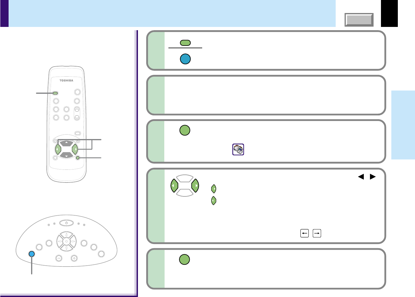
Press P.MODE and hold for two seconds.
The projector enters into the presentation mode.
The icon
appears in the presentation mode.
Select the computer input with INPUT.
You can change the order of procedure 1 to 3.
INPUT
INPUT
P.MODE
Change a slide with the selection buttons ( / ).
: Advancing to the next slide.
: Returning to the previous slide.
•The selection buttons of the main unit can not be used.
•The slide can not be switched even if you press and hold the
selection buttons continuously.
(The function is different from the , keys of the computer.)
6
7
When the presentation is finished;
To exit the presentation mode, press P.MODE.
The projector returns to the normal mode.
P.MODE
42
CONTENTS
Adjustments &
Settings
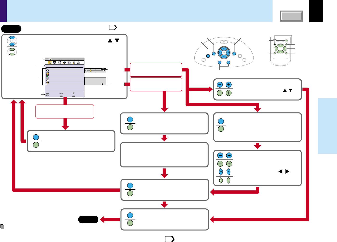
Operating the menu screen
Continued
FULL
Item
Next
Quit
Adjust the image brightness.
Select the image with its brightness priority or quality
(
color
)
priority.
Correct the keystone distortion of the screen.
Select the input source when changing the input.
Adjust the image flicker.
EXIT
ENTER
MENU
GUIDE MENU
Analog RGB
Items
Button operation guide
The current input source
MENU
ENTER
CT-90106
EXIT /
P.MODE
VOL
/
ADJ
End
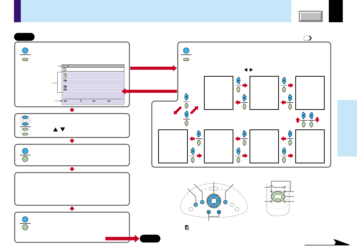
Press MENU.
Then GUIDE MENU appears.
(Then FULL MENU
appears if the latest operation had been finished with the
FULL MENU and afterwards power is not turned off.)
When you make more
detailed adjustments
and settings, call the
FULL MENU.
Return to the GUIDE MENU when
the MENU button is pressed.
Press MENU button once again.
The FULL MENU of [Picture] appears.
FULL MENU has seven pages of [Picture], [Position], [Color], [Audio],
[Display], [Default setting] and [Reset].
Use the selection button ( ) to change the page of FULL MENU.
/
[Picture][Position][Color]
[Default setting]
[Reset][Display][Audio]
Select the item with the selection
button ( ).
/
Press ENTER to confirm.
The item selected can be adjusted or set.
Press EXIT and return.
When you select other items, press EXIT repeatedly
until GUIDE MENU appears.
When you want to quit, press EXIT repeatedly until
GUIDE MENU disappears.
Start
FULL MENU: For the operating instruction, refer to the next page. GUIDE MENU:
You can adjust or set the functions used frequently.
Adjust and set it with the button indicated
on the button operation guide.
According to the selected item, the kind ([adjustment],[setting]
or [execution]) and the button to be used are indicated on the
button operation guide.
Control panel (Main unit side)
Remote control
K
E
Y
S
T
O
N
E
A
U
T
O
S
E
T
E
X
I
T
ON / STANDBY
VOL / ADJ
E
N
T
E
R
M
E
N
U
I
N
P
U
T
F
A
N
T
E
M
P
L
A
M
P
O
N
Selection
VOL/ADJ
Selection
MENU
ENTER
EXIT
VOL/ADJ
MENU
ENTER
EXIT
MENU
MENU
MENU
MENU
ENTER
ENTER
EXIT
EXIT
43
Various adjustments and settings can be made on the menu screen. The basic operations on the menu screen are shown here.
Note
The item displayed on the menu with gray is not available.
43
CONTENTS
Adjustments &
Settings
Operating the menu screen
(continued)
Analog RGB
GUIDE
Item
Execute
Quit
Picture
Contrast
-12-
-12-
Bright
Full
Full
Thru
Brightness
Picture mode
Screen size
Reset
EXIT
ENTER
MENU
Page
Adjust
Kind (page) of
FULL MENU
Items
Button operation guide
The current input source
Adjustment
display bar
Choices
End
Select the item with selection buttons ( ).
State of a figure below is a sample for explanation.
This state does not in fact.
/
Press ENTER.
The Item selected is executed. FULL
MENU is displayed after execution.
Press ENTER.
An object can be selected from the
sub menu list.
Start
Select it with the button indicated
on the button operation guide.
For the selection method of FULL MENU, refer to
the previous page.
Press ENTER.
Only the (small list of the) selected
adjusting items is displayed.
This is useful as you can see a main
picture not hidden under FULL MENU.
Adjust with VOL/ADJ (+/-) or
selection buttons ( ).
/
Press EXIT.
FULL MENU is displayed and you can
select other items.
Press EXIT.
FULL MENU disappears, and
adjustment or setting is finished.
Method -1
Method -2
Adjust with VOL/ADJ (+/-)
Press the selection button ( )
when selecting other items continuously.
/
MENU
ENTER
CT-90106
EXIT /
P.MODE
VOL
/
ADJ
Control panel (Main unit side)
Remote control
K
E
Y
S
T
O
N
E
A
U
T
O
S
E
T
E
X
I
T
ON / STANDBY
VOL / ADJ
E
N
T
E
R
M
E
N
U
I
N
P
U
T
F
A
N
T
E
M
P
L
A
M
P
O
N
Selection
VOL/ADJ
Selection
MENU
ENTER
EXIT
VOL/ADJ
MENU
ENTER
EXIT
ENTER
ENTER
ENTER
ENTER
ENTER
ENTER
EXIT
EXIT
EXIT
EXIT
At the items whose [Execute] is
displayed on the operation guide;
At the items whose the
adjustment bar is displayed;
At the items whose the
choices are displayed;
42
Notes
•The item displayed on the menu with gray is not available.
•An exclusive menu is displayed when making PIP function sub-picture settings.
52
44
CONTENTS
Adjustments &
Settings
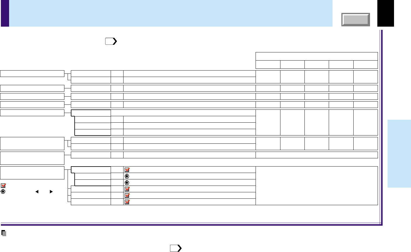
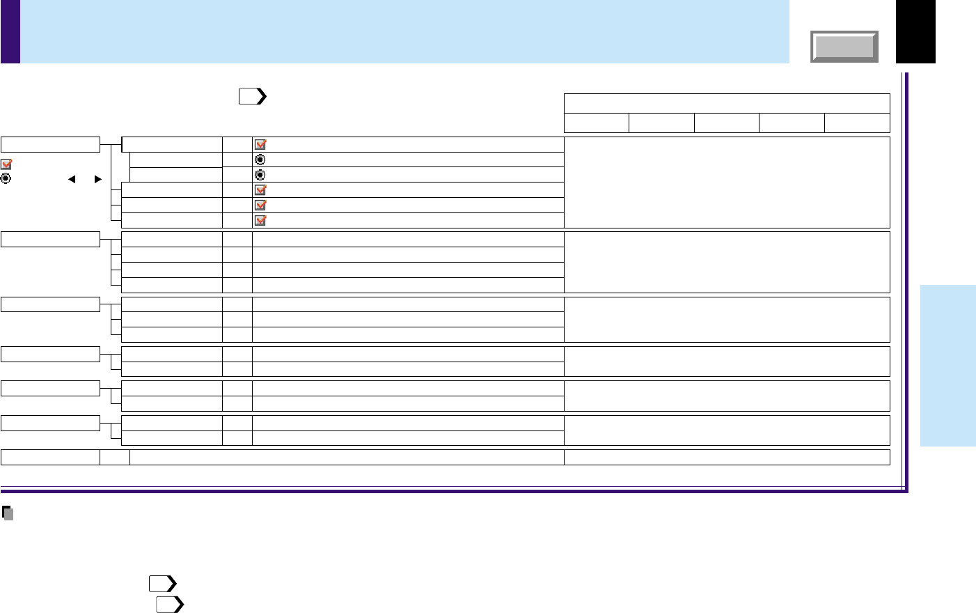
GUIDE MENU adjustments and settings
Adjust the contrast of the picture.
Adjust the brightness of the picture.
Adjust
the
flicker of the picture. (Sampling clock phase adjustment)
The picture is set with its brightness priority.
The picture is set with its color quality priority.
Adjust the keystone distortion.
Adjust the color depth of the picture.
Adjust the document imaging camera's gain.
Select a shutter speed below to decrease the flickering of the document imaging camera's picture.
The shutter speed is set automatically.
The shutter speed is fixed to 50 Hz.
The shutter speed is fixed to 60 Hz.
:
COMPUTER connector is selectable with the INPUT button.
: Video input is selectable with the INPUT button.
: Use COMPUTER
connector
as Analog RGB input.
: Use COMPUTER
connector
as Y/P
B
/P
R
input.
: S-Video input is selectable with the INPUT button.
: Camera input is selectable with the INPUT button.
Ye s
(common for all of the inputs)
Ye s
(common for all of the inputs)
-
-
-
Ye s
Ye s
-
-
-
-
Ye s
Ye s
-
-
-
-
Ye s
Ye s
-
Ye s
Ye s
-
Ye s
-
-
Ye s
-
-
Ye s
-
Ye s
Y/P
B
/P
R
Video
The relationship between input source and item Yes: Adjustable -: Not displayed
S-VideoCamera
Analog RGB
Adjust the image brightness.
Contrast
Brightness
ADJ.
ADJ.
Adjust the image flicker.
PhaseADJ.
Select the image with its brightness
priority or quality (color) priority.
BrightSET
True colorSET
Correct the keystone distortion
of the screen.
KeystoneADJ.
VIDEOSET
Select the input source when
changing the input.
SET
COMPUTER
SETAnalog RGB
SETY/P
B
/P
R
S-VIDEOSET
CAMERASET
Adjust the image color.
ColorADJ.
Camera gainADJ.
Shutter
SETAuto
SET50Hz
SET60Hz
: On/Off with ENTER
: On/Off with ( ) or ( )
Adjust the gain of the document imaging camera.
Reduce the flicker.
On GUIDE MENU, you can set or adjust the functions frequently used.
To operate GUIDE MENU, refer to page
42
.
Notes
•The items related to the camera (the document imaging camera) are displayed only with models having a camera.
•“Sampling phase” is adjusted and memorized for each RGB signal
69
.
•“Keystone” and “Input source setting” can be adjusted (set) at all input sources, but the adjustments (settings) made at one input source are applied to all
input sources.
•It is impossible to exit from the menu if no input source is selected.
•If the check in the check box for the currently selected source is removed, the setting becomes effective the next time the input is changed.
•The adjustments or settings made are memorized automatically when the power is turned off by pressing the ON/STANDBY button. If the power cord is
unplugged or if a power failure occurs while the projector is on, the adjustments or settings are not memorized.
45
CONTENTS
Adjustments &
Settings
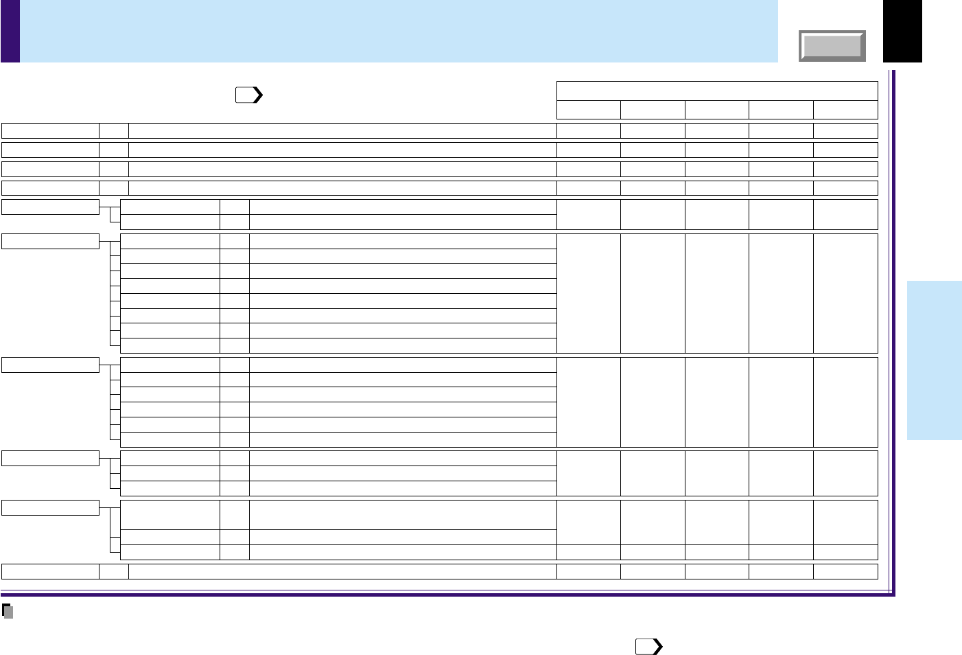
FULL MENU adjustments and settings - Picture
Adjust the contrast of the picture.
Adjust the brightness of the picture.
Adjust the sharpness of the picture.
(In Y/PB/PR input mode, sharpness is a setting item.)
The picture is set with its brightness priority.
The picture is set with its color quality priority.
Adjust the document imaging camera's gain.
The video mode (color system) is set automatically.
The video mode is fixed to NTSC system.
The video mode is fixed to
PAL system.
The video mode is fixed to
SECAM system.
The video mode is fixed to
PAL-N system.
The video mode is fixed to
PAL-M system.
The video mode is fixed to
PAL60 system.
The video mode is fixed to
NTSC4.43 system.
The Y/P
B/PR signal format is set automatically.
The Y/P
B/PR signal format is fixed to 480i (525i) mode.
The Y/P
B/PR signal format is fixed to 480p (525p) mode.
The Y/P
B/PR signal format is fixed to 575i (625i) mode.
The Y/P
B/PR signal format is fixed to 720p (750p) mode.
The Y/P
B/PR signal format is fixed to 1080i (1125i) mode.
The
shutter speed
is set automatically.
The
shutter speed
is fixed
at 50 Hz.
The
shutter speed
is fixed
at 60 Hz.
The picture is displayed with the input source resolution.
The picture is converted to wide screen format.
Return the adjustments and settings of FULL MENU [Picture] to the factory default values.
-
-
Ye s
Ye s
Ye s
Ye s
Ye s
-
Ye s
-
-
-
Ye s
Ye s
-
Ye s
Ye s
-
Ye s
Ye s
-
-
Ye s
Ye s
-
Ye s
Ye s
-
Ye s
Ye s
-
-
Ye s
Ye s
Ye s
-
Ye s
Ye s
-
Ye s
-
-
Ye s
Ye s
-
Ye s
Ye sYe sYe s
TLP251: Yes
TLP551: -
Ye s
-
-
-
Ye s
Y/PB/PR
Video
The relationship between input source and item Yes: Adjustable -: Not displayed
S-VideoCamera
Analog RGB
Contrast
Brightness
ADJ.
ADJ.
SharpnessADJ.
Picture modeBrightSET
True colorSET
Camera gainADJ.
Reset
EXEC.
Video modeAuto.SET
NTSCSET
PALSET
SECAMSET
PAL-NSET
PAL-MSET
PAL60SET
NTSC4.43SET
Signal formatAuto.SET
480i (525i)SET
480p (525p)SET
575i (625i)SET
720p (750p)SET
1080i (1125i)SET
ShutterAuto.SET
50HzSET
60HzSET
Screen size
Full
TLP550/551: The picture is converted to XGA (1024 x 768 dot) resolution.
TLP250/251: The picture is converted to SVGA (800 x 600 dot) resolution.
SET
ThruSET
WideSET
You can make various adjustments or settings of the picture from FULL MENU [Picture].
To operate FULL MENU, refer to page
43
.
Notes
•The items related to the camera (the document imaging camera) are displayed only with models having a camera.
•A part of function is restricted if you set the “Video mode” or “Signal format” to the modes other than [Auto.] .
50
•The adjustments or settings made are memorized automatically when the power is turned off by pressing the ON/STANDBY button. If the power cord is
unplugged or if a power failure occurs while the projector is on, the adjustments or settings are not memorized.
46
CONTENTS
Adjustments &
Settings
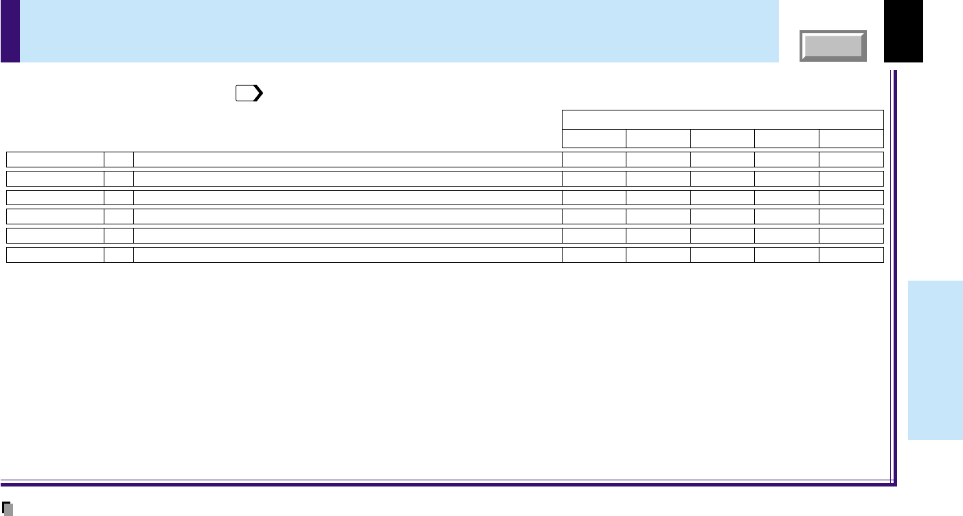
FULL MENU adjustments - Position
Adjust the horizontal display position of the picture.
Adjust the vertical display position of the picture.
Adjust the flicker of the picture. (Sampling clock phase adjustment)
Adjust the sampling frequency of the input signal if vertical stripes appear in the detailed image.
Return the adjustments of FULL MENU [Position] to the factory default values.
-
-
-
-
-
-
-
-
-
-
-
-
-
-
-
-
-
-
-
-
Ye s
Ye s
Ye s
Ye s
Ye s
Y/PB/PR
Video
The relationship between input source and item Yes: Adjustable -: Not displayed
S-VideoCamera
Analog RGB
H-position
V-position
ADJ.
ADJ.
PhaseADJ.
Frequency
ADJ.
Reset
EXEC.
You can adjust the picture position etc. of the analog RGB input from FULL MENU [Position].
To operate FULL MENU, refer to page
43
.
Notes
•This menu is not displayed except with analog RGB input.
•The adjustment of each item in this menu is memorized for each RGB signal input
69
.
•The adjustments made are memorized automatically when the power is turned off by pressing the ON/STANDBY button. If the power cord is unplugged
or if a power failure occurs while the projector is on, the adjustments are not memorized.
47
CONTENTS
Adjustments &
Settings
FULL MENU adjustments - Color
Adjust the color depth of the picture.
Adjust the tint of the picture. (Not adjustable at PAL, SECAM, PAL-N,PAL-M and PAL60)
Adjust the red level of the picture.
Adjust the green level of the picture.
Adjust the blue level of the picture.
Return the adjustments of FULL MENU [Color] to the factory default value.
Ye s
Ye s
Ye s
Ye s
-
-
Ye s
Ye s
Ye s
Ye s
-
Ye s
Ye s
Ye s
Ye s
Ye s
Ye s
Ye s
Ye s
Ye s
Ye s
Ye s
Ye s
Ye s
Ye s
Ye s
Ye s
Ye s
-
-
Y/P
B
/P
R
Video
The relationship between input source and item Yes: Adjustable -: Not displayed
S-VideoCamera
Analog RGB
Color
Tint
ADJ.
ADJ.
R-levelADJ.
G-levelADJ.
B-levelADJ.
Reset
EXEC.
You can adjust the color condition of the picture from FULL MENU [Color].
To operate FULL MENU, refer to page
43
.
Note
The adjustments made are memorized automatically when the power is turned off by pressing the ON/STANDBY button. If the power cord is
unplugged or if a power failure occurs while the projector is on, the adjustments are not memorized.
48
CONTENTS
Adjustments &
Settings
FULL MENU adjustments and settings - Audio
Adjust the sound volume emitted from the speaker.
The sound is emitted from the speaker.
No sound is emitted from the speaker.
Return the adjustments and settings of FULL MENU [Audio] to the factory default values.
The loudness effect is added to the speaker sound.
The loudness effect is not added to the speaker sound.
The sound of the left and right channels is mixed and emitted from the speaker.
Only the sound of the left input channel is emitted from the speaker.
Only the sound of the right channel is emitted from the speaker.
Ye s
(common)
Ye s
(common)
Ye s
(common)
Ye s
(common)
Ye sYe sYe sYe s
-
-
-
-
-
Y/P
B
/P
R
Video
The relationship between input source and item Yes: Adjustable -: Not displayed
S-VideoCamera
Analog RGB
VolumeADJ.
Speaker outputOnSET
OffSET
Reset
EXEC.
LoudnessOnSET
OffSET
Channel selectL+RSET
LSET
RSET
You can set the sound emitted from the speaker from FULL MENU [Audio].
To operate FULL MENU, refer to page
43
.
Notes
•When the camera input is selected, sound is not emitted.
•Each item can be set at every input source except the camera input, but the settings made at one input source are applied to all input sources as shown
in the table. The sound volume can be adjusted for each input source except the camera input.
•The adjustments or settings made are memorized automatically when the power is turned off by pressing the ON/STANDBY button. If the power cord is
unplugged or if a power failure occurs while the projector is on, the adjustments or settings are not memorized.
49
CONTENTS
Adjustments &
Settings
FULL MENU adjustments and settings - Display
Adjust the keystone distortion caused by changing the installation angle.
Menus and messages are displayed in English.
Menus and messages are displayed in French.
Menus and messages are displayed in
Portuguese.
Menus and messages are displayed in
Japanese.
Menus and messages are displayed in German.
Menus and messages are displayed in Italian.
Menus and messages are displayed in
Spanish.
Menus and messages are displayed in Chinese (Simplified).
Menus and messages are displayed in Chinese (Traditional).
Menus and messages are displayed in Korean.
The icon is displayed.
The icon is not displayed.
The menu background becomes translucent.
The menu background is normal.
The menu is displayed at the upper left of the screen.
The menu is displayed at the upper right of the screen.
The menu is displayed at the lower left of the screen.
The menu is displayed at the lower right of the screen.
Return the adjustments and settings of FULL MENU [Display] to the factory default values.
Ye s
(common for all of the inputs)
Ye s
(common for all of the inputs)
Ye s
(common for all of the inputs)
Ye s
(common for all of the inputs)
Ye s
(common for all of the inputs)
Ye s
(common for all of the inputs)
Y/P
B
/P
R
Video
The relationship between input source and item Yes: Adjustable -: Not displayed
S-VideoCamera
Analog RGB
KeystoneADJ.
Language
English
SET
Français
SET
IconOn
Off
Reset
EXEC.
Português
SET
SET
Deutsch
SET
Italiano
SET
Español
SET
SET
SET
SET
SET
SET
Menu translucent
On
Off
SET
SET
Menu positionUpper left
Upper right
SET
SET
Lower left
SET
Lower right
SET
You can set the language, menu display, etc. from FULL MENU [Display].
To operate FULL MENU, refer to page
43
.
Notes
•Each item can be set at all input sources, but the settings made at one input source are applied to all input sources.
•The adjustments or settings made are memorized automatically when the power is turned off by pressing the ON/STANDBY button. If the power cord is
unplugged or if a power failure occurs while the projector is on, the adjustments or settings are not memorized.
•The setting of “Menu translucent” is not available if no signal is input. Also, the background of the menu will not be translucent, regardless of the settings.
50
CONTENTS
Adjustments &
Settings
FULL MENU settings - Default setting
Return the settings of FULL MENU [Default setting] to the factory default values.
The projector is set to the floor-mounted front projection mode.
The projector is set to the floor-mounted rear projection mode.
The projector is set to the ceiling-mounted front projection mode.
The projector is set to the ceiling-mounted rear projection mode.
The TOSHIBA logo is displayed when no signal is input.
The entire screen is set to blue when no signal is input.
Nothing is displayed when no signal is input.
The power does not turn off automatically even if no signal status continues.
The power turns off automatically when no signal status continues for approx. 5 min.
: COMPUTER connector is selectable with the INPUT button.
: Video input is selectable with the INPUT button.
: Use COMPUTER connector as Analog RGB input.
: Use COMPUTER connector as Y/PB/PR input.
: S-Video input is selectable with the INPUT button.
: Camera input is selectable with the INPUT button.
The power turns on by pressing the ON/STANDBY button.
When the power plug is inserted, the power is on.
The start-up display appears when the power is turned on.
The start-up display does not appear when the power is turned on.
VIDEOSET
Input source setting
SETCOMPUTER
SETAnalog RGB
SETY/PB/PR
S-VIDEOSET
CAMERASET
Ye s
(common for all of the inputs)
Ye s
(common for all of the inputs)
Ye s
(common for all of the inputs)
Ye s
(common for all of the inputs)
Ye s
(common for all of the inputs)
Ye s
(common for all of the inputs)
Ye s
(common for all of the inputs)
Y/PB/PR
Video
The relationship between input source and item Yes: Adjustable -: Not displayed
S-VideoCamera
Analog RGB
Reset
EXEC.
Projection modeStandardSET
RearSET
CeilingSET
Rear ceilingSET
Background
LogoSET
BlueSET
NoneSET
No signal power off
OffSET
5 min.SET
Power onManualSET
Auto.SET
Start-up screenOnSET
OffSET
: On/Off with ENTER
: On/Off with ( ) or ()
You can set the Input source, projection mode, etc. from FULL MENU [Default setting].
To operate FULL MENU, refer to page
43
.
Notes
•It is impossible to exit from the menu if no input source is selected.
•If the check in the check box for the currently selected source is removed, the setting becomes effective the next time the input is changed.
•In the following conditions, the function to detect no signal (“No signal background”, “No signal power off”) does not activate:
1) When “Video mode”
45
is set to the modes other than [Auto] and Video input or S-Video input is selected.
2) When “Signal format”
45
is set to the modes other than [Auto] and Y/PB/PR input is selected.
•Note that the projector automatically powers up at the restoration of power after a failure, if “Power on” is set to [Auto] with the power plug inserted.
•Even if “Power on” is set to [Auto], the setting of [5 min.] of “No signal power off” is effective.
•Each item can be set at all input sources, but the settings made at one input source are applied in common to all input sources.
•The settings made are memorized automatically when the power is turned off by pressing the ON/STANDBY button. If the power cord is un-plugged or if
a power failure occurs while the projector is on, the settings are not memorized.
51
CONTENTS
Adjustments &
Settings
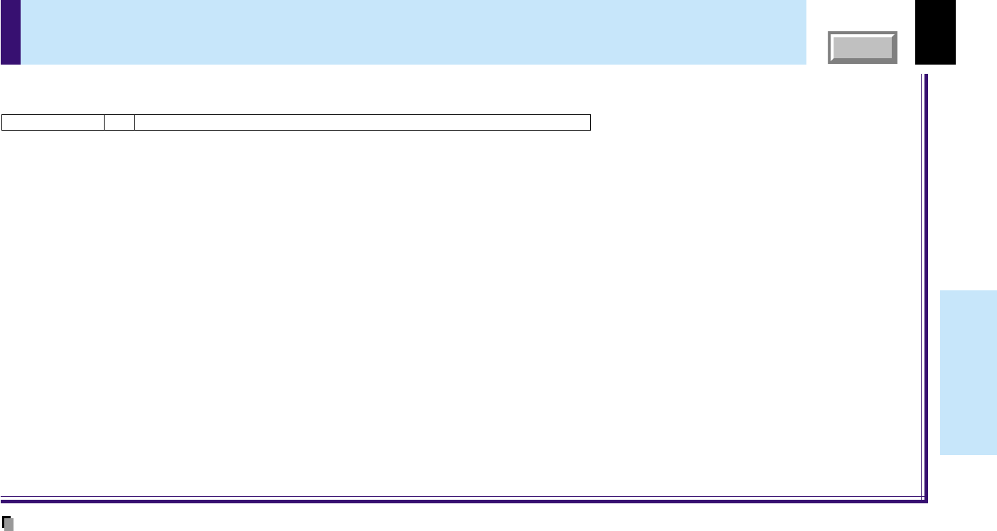
FULL MENU settings - Reset
Return the adjustments and settings of all menus to the factory default setting.Reset all
EXEC.
You can return the adjusting and setting values of all menus to the factory default setting.
Note
The resettings made are memorized automatically when the power is turned off by pressing the ON/STANDBY button. If the power cord is
unplugged or if a power failure occurs while the projector is on, the resettings are not memorized.
52
CONTENTS
Adjustments &
Settings
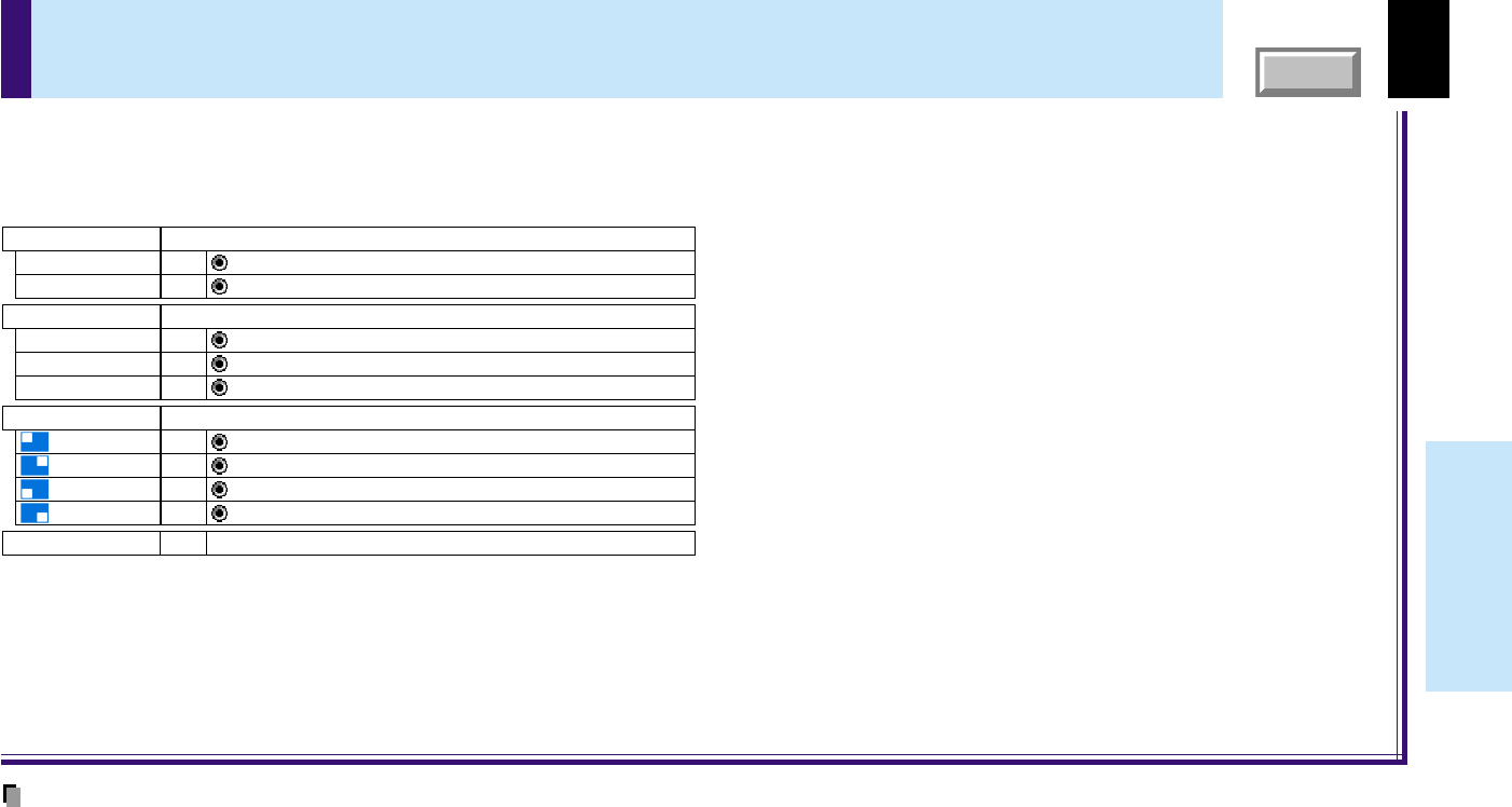
PIP menu setting
Return the settings of PIP MENU to the factory default setting.
Select the signal source for PIP sub-picture.
Set the PIP sub-picture size.
: Video input is selected as signal source.
: S-Video input is selected as signal source.
: The PIP sub-picture size is set to small.
: The PIP sub-picture size is set to medium.
: The PIP sub-picture size is set to large.
Set the PIP sub-picture display position.
:
The sub-picture is displayed at the upper left of the screen.
:
The sub-picture is displayed at the upper right of the screen.
:
The sub-picture is displayed at the lower left of the screen.
:
The sub-picture is displayed at the lower right of the screen.
Reset
EXEC.
Source
SETVideo
SETS-Video
Size
SETSmall
SETMedium
SETLarge
Position
SET
SET
SET
SET
When a PIP sub-picture is displayed, the PIP menu screen will appear if you press the MENU button.
You can make the PIP sub-picture settings when a PIP subpicture is displayed.
To cancel the menu, press the EXIT button.
Notes
•The size of the PIP sub-picture differs according to the signal type (resolution) of the main picture.
•The settings made are memorized automatically when the power is turned off by pressing the ON/STANDBY button. If the power cord is unplugged or if a
power failure occurs while the projector is on, the settings are not memorized.
53
CONTENTS
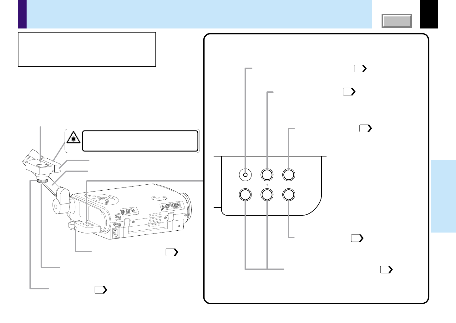
Document
imaging camera
Camera head
Camera lens
Arm
Infrared remote sensor
LED light
Camera control panel
Focusing ring
LOCK (W.BALANCE) indicator
Lights when the white balance is locked.
W.BALANCE button
To switch white balance settings between
automatic adjustment and lock.
ARM LIGHT button
To turn on or off the light.
CAMERA GAIN (+/
-
) buttons
To adjust the camera gain.
CAMERA button
To select the camera source. Press again
to return to the previous input source.
57
56
55
58
58
16
56
CAMERA
ARM LIGHT
LOCK
W.BALANCE
CAMERA
GAIN
IEC 60825-1,
Am.1 1997
LED RADIATION
DO NOT STARE INTO BEAM
CLASS 2 LED PRODUCT
WAVE LENGTH : 425-750nm
MAX OUTPUT :
LESS THAN 1mW
RAYONNEMENT LED
NE PAS REGARDER DANS LE FAISCEAU
APPAREIL A LED DE CLASSE 2
LONGUEUR D'ONDE : 425-750nm
PUISSANCE MAXIMA :
AU-DESSOUS DE 1mW
LED-STRAHLUNG
NICHT IN DEN STRAHLBLICKEN
LED KLASSE 2 PRODUKT
WELLENLÄNGE : 425-750nm
MAX AUSGANGSLEISTUNG :
UNTER 1mW
Part names (of the document imaging camera model)
CAUTION
When using the camera, be careful not to
pinch your hand or fingers into the arm.
On the document imaging camera model, you can
project pictures using the document imaging camera.
The document imaging camera can directly project any
materials (documents, illustrations, etc.) without using an
OHP film.
54
CONTENTS
Document
imaging camera
Note
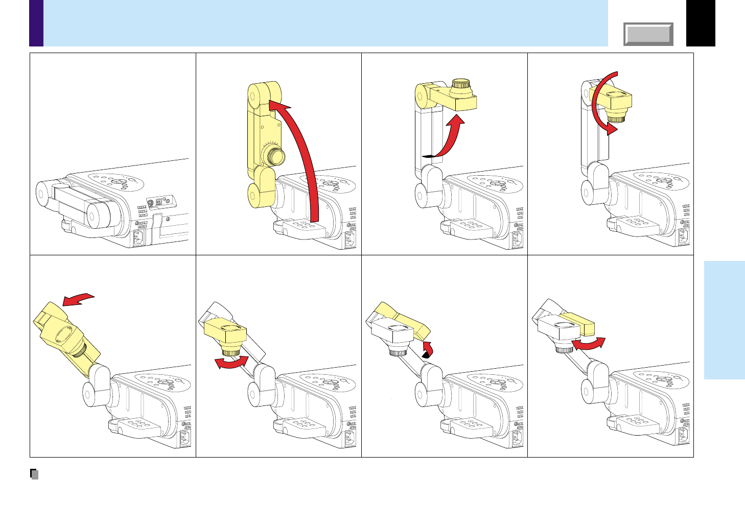
Never give shocks or impacts to the camera or arm as this may cause malfunction.
Preparation of the document imaging camera
1) Raise up the arm.
Before preparations
(stowed away)
2) Pull up the camera head.3) Turn the camera head.
4) Incline the arm backward.6) Pull up the light.7) Turn the light.
5) Move the camera head
toward the object.
55
CONTENTS
Document
imaging camera
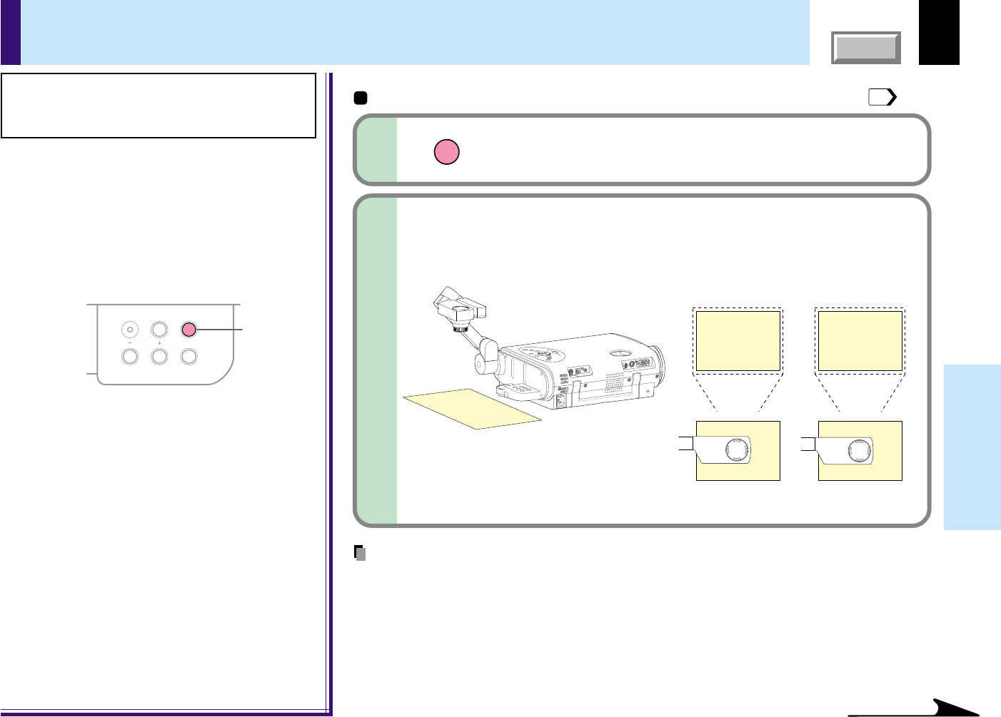
Picture projection with the document imaging camera
CAMERA
ARM LIGHT
LOCK
W.BALANCE
CAMERA
GAIN
1
CAUTION
Do not look into the arm light while it is lit.
Preparation
1
Project a picture on the screen as explained in the step “Projection on the screen”.
27
Press ARM LIGHT.
The light turns on.
1
ARM LIGHT
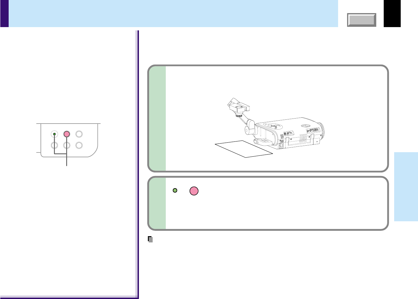
Set a document to be projected.
Place the document (illustrations, etc.) onto or around the
projector, and turn the camera head to the direction of the
document.
2
123
123
123123
123
Continued
Images on the screen
Setting direction
Camera control panel
Notes
•Do not leave documents on the unit or near of the air exhaust for long periods of time. The
heat could erase or discolor the letters on a thermal paper.
•Use the arm light when necessary according to the brightness of the room.
56
CONTENTS
Document
imaging camera
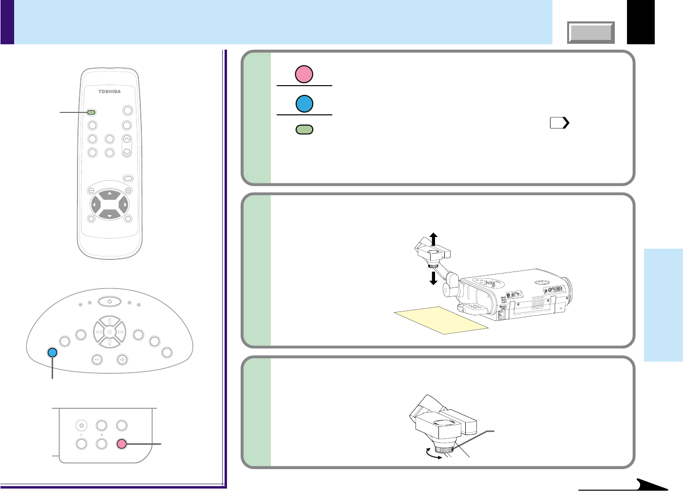
Press CAMERA to select the camera input mode.
•Pressing CAMERA again will return the input selection to the
previous mode.
•You can also select it by pressing INPUT on the remote
control or on the main unit. Set the input source on the menu
screen when selecting by the INPUT button.
29
•The CAMERA button can be used regardless of the input
setting.
•“Camera” is displayed when the picture switches to the
document imaging camera’s picture.
3
Continued
MENU
ON /
INPUT
ENTER
CT-90106
KEYSTONEAUTO SET
EXIT /
P.MODE
PIP
FREEZE
MUTE
CALL
RESIZE
VOL
/
ADJ
STANDBY
K
E
Y
S
T
O
N
E
A
U
T
O
S
E
T
E
X
I
T
ON / STANDBY
VOL / ADJ
E
N
T
E
R
M
E
N
U
I
N
P
U
T
F
A
N
T
E
M
P
L
A
M
P
O
N
3
3
CAMERA
ARM LIGHT
LOCK
W.BALANCE
CAMERA
GAIN
3
Picture projection with the document imaging camera (continued)
Move the camera head to adjust the size of the picture.
4
Focus on the picture by turning the focusing
ring on the camera head.
5
123
Up: To reduce.
Down: To enlarge.
Focusing ring
Remote control
Control panel
(Main unit side)
Camera control panel
INPUT
INPUT
CAMERA
57
CONTENTS
Document
imaging camera
Press CAMERA GAIN (+/-) to improve view of a
camera subject which is too dark or vivid.
6
Notes
•You can adjust the “Sharpness” of the camera image on the menu screen.
45
•If the image flickers due to a fluorescent light in the room, either turn off the fluorescent light or
set the “Shutter” on the menu screen.
45
Note that the image may still flicker due to the lighting, the document status, the image
adjustment, etc., even if the “Shutter” setting is changed.
CAMERA
GAIN
CAMERA
ARM LIGHT
LOCK
W.BALANCE
CAMERA
GAIN
6
Picture projection with the document imaging camera (continued)
When finished, turn off the light and close it,
and put back the arm.
Follow the steps of “Preparation of the document imaging
camera” in reverse.
7
Notes
•The light turns off automatically when the arm is inclined.
•When the arm is not raised up, the camera source cannot be projected.
•In the camera input selected, the sound is not emitted.
Camera control panel
58
CONTENTS
Document
imaging camera
This projector ’s camera is always being adjusted automatically for projected color balance;
however, the balance can shift away from optimum due to the color scheme of the
document. Should this occur, the white balance can be set to a fixed condition by using the
following procedure.
1
Project a white paper and enlarge it to fill the
screen.
Notes
•If you raise up the arm while the camera input is being selected, the color of the picture may
vary for an instant due to the automatic white balance adjustment. This is not a malfunction.
•If you put the arm back and raise it again while the white balance is locked (the LOCK
indicator is lit), the projector will release the white balance.
•Should this be the case, or if you would like to adjust it to a desired tint, adjust
“R-level”, “G-level” or “B-level” on the FULL MENU [Color] screen.
Locking the white balance
LOCK
W.BALANCE
CAMERA
ARM LIGHT
LOCK
W.BALANCE
CAMERA
GAIN
2
2
Press W.BALANCE to turn the LOCK indicator
on.
The white balance is locked.
To release the white balance, press W.BALANCE again to turn
the LOCK indicator off.
Camera control panel
59
CONTENTS
Document
imaging camera
With the document camera operating, fully
cover the camera lens with a piece of black
paper or cloth.
1
Correcting illuminated defects
Note
Do not press ARM LIGHT and EXIT buttons simultaneously if the camera lens is not
covered. Doing so will not only erase the white spot correction data already set but also
result in parts ot the image that are properly displayed being corrected. Also be careful if
the camera input mode is not selected.
ARM LIGHT
EXIT
CAMERA
ARM LIGHT
LOCK
W.BALANCE
CAMERA
GAIN
2
K
E
Y
S
T
O
N
E
A
U
T
O
S
E
T
E
X
I
T
ON / STANDBY
VOL / ADJ
E
N
T
E
R
M
E
N
U
I
N
P
U
T
F
A
N
T
E
M
P
L
A
M
P
O
N
Press ARM LIGHT on the camera control panel
and EXIT on the projector’s control panel
simultaneously.
You can not use the remote control buttons.
2
Camera control panel
Control panel
(Main unit side)
Press both sides
Camera lens
For the CCD image sensor used in the camera unit, in rare cases some of the pixels may
be disturbed due to the influence of cosmic rays, etc. This disturbance may cause white
spots to appear on the picture.
If white spots appear on the document camera image, use the procedure described below
to correct the problem.
60
Maintenance
CONTENTS
If there is some problem inside the projector,
the indicators light up or blink.
Trouble indications
Indicators
Or
(Lit in red)
(Off)
ON
LAMP
TEMP
FAN
(Lit in red)
(Lit in red)
ON
LAMP
TEMP
FAN
(Flashing
in orange)
ON
LAMP
TEMP
FAN
(Lit in red)
ON
LAMP
TEMP
FAN
(Lit in red)
Or
(Lit or flashing
in red)
(Lit or flashing
in orange)
Or
Or
Or
(Lit in red)
(Lit in red)
(Lit in green)
(Lit in green)
(Lit in orange)
O
N
LAMP
TEMP
FAN
(off)
The power does not come on.
→ Malfunction of the unit.
•Unplug the power cord and call the dealer.
The lamp turns off or does not light up.
→ The projector will return to the standby mode in about 2 minutes.
If the projector does not operate normally when the power is switched on again,
the lamp is at the end of its life duration or the unit has a fault.
•Lamp's life duration is over, replace the lamp with a new one.
•Unplug the power cord and call the dealer.
The power turns off or does not come on.
→ The inside is too hot, or the projector has been working in an area of high
temperature.
•Place the projector correctly so the intake and exhaust fan's holes are notcovered.
•Turn the projector off, and leave it for a while, and turn it on again.
•Clean the air filter.
* The icon appears before the power turned off.
* The projector returns to the standby mode after the fault display has been shown
for about 2 minutes.
The power turns off or does not come on.
→ Trouble with the cooling fan.
•Unplug the power cord and call the dealer.
* The icon appears before the power turned off.
* The projector returns to the standby mode after the fault display has been shown
for about 2 minutes.
The power turns off or does not come on.
→ The lamp cover is not properly attached.
•Unplug the power cord and reattach the lamp cover.
* The icon appears before the power turned off.
* The projector returns to the standby mode after the fault display has been shown
for about 2 minutes.
64
61
65
K
E
Y
S
T
O
N
E
A
U
T
O
S
E
T
E
X
I
T
ON / STANDBY
VOL / ADJ
E
N
T
E
R
M
E
N
U
I
N
P
U
T
F
A
N
T
E
M
P
L
A
M
P
O
N
Control panel
(Main unit side)
Notes
•If abnormality occurs while operating, unplug the power cord.
•When reinserting the power cord before the lamp has cooled, please wait until the lamp has
cooled sufficiently before use. When the lamp is at a high temperature, it may not light and the
life duration will be shortened.
61
Maintenance
CONTENTS
Air filter cleaning
CAUTION
If you use the projector mounted on the ceiling,
ask the dealer to carry out the maintenance
such as cleaning.
The filter inside the air filter cover is the part
to shut out dusts or dregs.
Do not use the projector with the filter taken
off.
We recommend you clean the air filter
frequently. (The cleaning period is once per
50 hours approximately).
2
1
Unplug the power cord.
Take off the front cover.
Slide the front cover rightward side for
about 3 mm, then the front cover can be
taken off toward you.
Detach the air filter.
Take off the filter frame by pulling the
middle part of it toward you, then detach
the air filter.
Clean the air filter.
Use a vacuum cleaner to carefully remove any dust and dirt from the front
cover, air filter and filter frame.
Be careful that the air filter is not sucked into the vacuum cleaner.
3
4
1
2
Continued
Air filter
Filter frame
Front cover
62
Maintenance
CONTENTS
Air filter cleaning (continued)
Mount the air filter and the filter frame.
Place the air filter in the projector, then insert the four tabs on the filter frame
into the holes in the projector.
Mount the front cover.
Insert the hooks of the front cover into the projector first, then slide it to the
lens side to fix it.
5
6
2
1
Air filter
Filter frame
Notes
•When the air filter is dusty, the ventilation is
impaired. This causes the temperature inside the
projector to rise, and may damage the unit.
•Attach the air filter and the filter frame firmly after
the cleaning. If it is not set correctly, the dusts will
enter and they will be projected and overlapped on
the picture.
•If you wash the air filter with water, be sure to let it
dry fully before reinstalling it. Using it damp will
result in malfunction.
•If the air filter is damaged, contact your store of
purchase and replace it with a new one. Using a
damaged air filter will cause dust or dirt to get
inside the projector and onto the images.
Front cover
1
2
63
Maintenance
CONTENTS
Cleaning the lens
Use a blower or a lens cleaner to clean the lens.
Never rub or tap the lens with a hard object as
the lens surface is fragile.
Lens and main unit cleaning
Cleaning the main unit
•Pull out the power cord before cleaning.
•Use a soft cloth to wipe off stains from the
surface.
•To remove difficult stains, use a soft cloth
slightly moistened with a weak solution of
synthetic detergent and water, and finish with
a soft, dry cloth.
Replacing the intake, exhaust fans and air filter
To maintain the efficiency of the projector, replace the intake and exhaust
fans about every two to three years.
Ask the dealer for the replacement.
CAUTION
If you use the projector mounted on the ceiling,
ask the dealer to carry out the maintenance
such as cleaning.
64
Maintenance
CONTENTS
Lamp replacement
The lamp will eventually begin to project dark
or dull pictures and finally will not light up.
(Lamp’s life depends on operating
conditions.) In such a case, replace the lamp
with new one.
CAUTION
•If you use the projector mounted on the ceiling,
ask the dealer to carry out the maintenance
such as cleaning or replacement of the lamp.
•When replacing, always use lamp “TLPL55”
(sold separately). For details, refer to the lamp
instruction.
•If you have been using the projector, the lamp
will be very hot, and may cause burn injuries.
Wait for the lamp to cool (for longer than 1
hour) before replacing it.
•If the lamp should break, please handle with
care to avoid injury due to broken pieces and
contact your dealer for repair service.
Unplug the power cord.
1
Wait until the lamp gets cool enough.
2
3
Take off the lamp cover on the
bottom panel.
Loosen the two screws, and pull off the
lamp cover.
Pull out the lamp.
Loosen the two fixing screws, and lift up the
handle to pull out the lamp.
4
2
3
1
Continued
Lamp cover
2
3
1
65
Maintenance
CONTENTS
Notes
•When the CALL button is pressed, the “Lamp
time” (the approximate amount of time the lamp
has been used) will be displayed.
39
•The lamp should be replaced if the total working
time exceeds about 1,500 hours.
When the “Lamp time” is displayed as 1500 hours,
the icon and a message appear. They will
disappear when you do some operation.
•Attach the lamp cover firmly after replacing the
lamp. If it is not set correctly, the power will not
turn on.
•Use a new lamp when replacing it.
•The lamp is made of glass and is very fragile. Do
not touch the lamp with your bare hands and do
not jolt or damage it. Do not try to use an
exhausted lamp.
A small amount of inorganic mercury harmful to
environment is used for the lamp. Dispose of the
exhausted lamp according to the rules of your
area.
Lamp replacement (continued)
5
Load a new lamp.
Slide until it hits the bottom and tighten the two fixing screws.
6
Attach the lamp cover.
Slide the cover into place and tighten the two
screws.
Reset the lamp timer.
Refer to the lamp instructions for resetting.
7
2
1
3
66
Others
CONTENTS
Before calling service personal
Symptom
The power does not come on.
The power turns off while
using the projector.
No image appears.
No sound is heard.
Desired input source cannot
be selected by the INPUT
button.
Analog RGB input or Y/P
B/PR
input colors are not right.
The image is blurred.
Focusing is uneven.
The picture is dim.
The color is faint.
The tint is not good.
Cause
•The power cord is disconnected.
•The lamp cover is not attached correctly.
•The ambient temperature of the projection room is too high.
•The lens cover is on.
•The wrong input is selected.
•The muting mode is on.
•The “Brightness” adjustment is at its darkest.
•The source is not correctly connected to the projector.
•The wrong input is selected.
•The muting mode is on.
•The sound volume is at it’s minimum.
•The source is not correctly connected to the projector.
•
Input is not set so that it can be selected with the INPUT button. By
default, only the Analog RGB and Video input modes can be selected.
•The COMPUTER connector's input setting is wrong.
•The lens is dirty.
•The picture is out of focus.
•The projection distance is not appropriate.
•The projecting light is not hitting the screen squarely.
•The “Brightness”, “Contrast”, “Sharpness” or “Phase” adjustments
are not correct.
•The “Brightness” or “Contrast” adjustments are not correct.
•The lamp life is ending.
•The “Color”, “Tint”, “R-Level”, “G-Level” or “B-Level” adjustments
are not correct.
•The lamp life is ending.
Correction
Firmly plug in the power cord.
Attach the cover correctly.
Lower the ambient temperature of the projection room,
and turn the power on.
Take off the lens cover.
Select the input source correctly.
Press MUTE to restore the picture.
Make the “Brightness” adjustment.
Connect the source correctly to the projector.
Select the input source correctly.
Press MUTE to restore the sound.
Adjust the sound volume.
Connect the source correctly to the projector.
Set from the menu screen so that the source can be
selected with the INPUT button.
On the menu screen, set for the proper input signal type.
Clean the lens with a blower or lens cleaner, etc.
Focus the picture.
Adjust the distance properly.
Adjust the projecting direction so that the light hits the
screen squarely.
Make the “Picture” adjustments.
Make the “Picture” adjustments.
Replace the lamp.
Make the “Color” adjustments.
Replace the lamp.
Page
19
65
60
19
29
35
44
23
-
25
29
35
31
23
-
25
44
29
44
63
30
18
18
45
45
64
47
64
Check the following points before asking for support service. Refer also to “Trouble indications”.
60
Continued
67
Others
CONTENTS
Symptom
The remote control does not
work.
The presentation made cannot
be used from the remote
control unit.
Document camera image is
blurry.
Document camera image
flickers.
Cause
•The remote control is not facing the remote sensor.
•The remote control is too far away.
•There is an obstruction between the remote control and the
remote sensor.
•The batteries are exhausted.
•The USB cable is not properly connected.
•The computer or OS is not compatible.
•The batteries are exhausted.
•The lens is dirty.
•The picture is out of focus.
•The light is not on.
•Image is being affected by fluorescent light in the room.
Correction
Face the remote control transmitter toward the remote
sensor on the projector.
Operate within about 5 meters.
Remove the obstacle.
Replace the batteries.
Connect the USB cable properly.
The remote control mouse function is not available.
Replace the batteries.
Clean the lens with a blower or lens cleaner, etc.
Focus the picture by turning the focus ring.
Turn on the light.
Set the shutter speed on the menu screen.
Page
16
16
–
15
40
–
15
63
56
55
44
Before calling service personal (continued)
68
Others
CONTENTS
Mini D-sub 15pin
connector
Pin assignment of COMPUTER connector
COMPUTER
Input signal
Analog R, G, B signal: 0.7V(p-p) 75Ω
Horizontal sync signal:
TTL level (positive/negative polarity)
Vertical sync signal:
TTL level (positive/negative polarity)
Y signal: 1.0V(p-p) 75Ω
PB, PR signal: 0.7V(p-p) 75Ω
Pin No.
1
2
3
4
5
6
7
8
9
10
11
12
13
14
15
RGB input
Video signal (Red)
Video signal (Green)
Video signal (Blue)
GND
GND
GND (Red)
GND (Green)
GND (Blue)
N.C
GND
GND
DDC data
Horizontal sync signal
Vertical sync signal
DDC clock
Y/PB/PR input
Color difference signal (P
R
)
Luminance signal (Y)
Color difference signal (P
B
)
*
*
GND (PR)
GND (Y)
GND (PB)
*
*
*
*
*
*
*
Description
*
: Do not connect anything.
51
10
1511
6
69
Others
CONTENTS
TEXT70640 x 35050640149680031.46970.08625.17559350382449
TEXT70640 x 40050640149680031.46970.08625.17534400132449
TEXT85640 x 35096640326483237.86185.08031.50060350323445
TEXT85640 x 40096640326483237.86185.08031.5004140013445
NEC PC98 24k640 x 40085640596484824.82055.90021.04725400118444
VGA60640 x 48048640169680031.46959.94025.17533480102525
VGA72640 x 480128640244083237.86172.80931.5002848093520
VGA75640 x 480120640166484037.50075.00031.5001648013500
VGA85640 x 48080640565683243.26985.00836.0002548013509
MAC13"640 x 48096640646486435.00066.66730.2403948033525
SVGA56800 x 6001288002472102435.15656.25036.0002260012625
SVGA60800 x 6008880040128105637.87960.31740.0002360014628
SVGA72800 x 6006480056120104048.07772.18850.00023600376666
SVGA75800 x 6001608001680105646.87575.00049.5002160013625
SVGA85800 x 6001528003264104853.67485.06156.2502760013631
*MAC16"832 x 6242168324064115249.72574.55057.2833963213667
*XGA43i1024 x 7685610248176126435.52243.47944.9002076804817
*XGA601024 x 768160102424136134448.36360.00465.0002976836806
*XGA701024 x 768144102424136132856.47670.06975.0002976836806
*XGA751024 x 76817610241696131260.02375.02978.7502876813800
*XGA851024 x 76820810244896137668.67784.99794.5003676813808
*MAC19"1024 x 76818010242096132060.19774.87273.2003076833804
V. Sync
Applicable computer signal
The unit is applicable to the following signals.
However, some computers may have
different timings than those in the chart.
Make the necessary adjustments if the
picture has flickers or is blurred.
Signal Timing (Horizontal)
Video
H. Sync
Signal Timing (Vertical)
Video
Applicable signal
Timing chart
Mode
Resolution
A
(Pixels)
B
(Pixels)
C
(Pixels)
D
(Pixels)
E
(Pixels)
fh
(kHz)
fv
(Hz)
Clock
(MHz)
G
(Lines)
H
(Lines)
I
(Lines)
J
(Lines)
K
(Lines)
D
AC
E
B
J
G
K
H
I
Continued
70
Others
CONTENTS
Applicable signal (continued)
Timing chart (Continued)
**SXGA1152x864 75Hz1152 x 864256115264128160067.50075.000108.0003286413900
**SXGA1280x960 60Hz1280 x 960312128096112180060.00060.000108.00036960131000
**SXGA1280x960 85Hz1280 x 960224128064160172885.93885.002148.50047960131011
**SXGA1280x1024 60Hz1280 x 1024248128048112168863.98160.020108.000381024131066
**SXGA1280x1024 75Hz1280 x 1024248128016144168879.97675.025135.000381024131066
**SXGA1280x1024 85Hz1280 x 1024224128064160172891.14685.024157.500441024131072
**UXGA601600 x 1200304160064192216075.00060.000162.000461200131250
**UXGA651600 x 1200304160064192216081.25065.000175.500461200131250
**UXGA701600 x 1200304160064192216087.50070.000189.000461200131250
**UXGA751600 x 1200304160064192216093.75075.000202.500461200131250
Mode
Resolution
A
(Pixels)
B
(Pixels)
C
(Pixels)
D
(Pixels)
E
(Pixels)
fh
(kHz)
fv
(Hz)
Clock
(MHz)
G
(Lines)
H
(Lines)
I
(Lines)
J
(Lines)
K
(Lines)
Notes
•Signal sources marked “
*
” and “
**
” are displayed in compressed format (“
*
”: TLP250/TLP251, “
**
”: TLP250/TLP251/TLP550/TLP551), so some of their
data may be missing or their picture quality may be degraded.
•With analog RGB inputs, if the signal source’s dot clock frequency exceeds 165 MHz, some pixel signals cannot be sampled.
The compatible Video and S-Video signal
The compatible components video signal (Y/PB/PR)
Mode
NTSC
PAL
SECAM
PAL-M
PAL-N
PAL-60
NTSC4.43
fh (kHz)
15.73
15.63
15.63
15.73
15.63
15.73
15.73
fv (Hz)
60
50
50
60
50
60
60
fsc (MHz)
3.58
4.43
4.25 or 4.41
3.58
3.58
4.43
4.43
Mode
480i (525i)
480p (525p)
575i (625i)
720p (750p)
1080i (1125i)
fh (kHz)
15.73
31.47
15.63
45.00
33.75
fv (Hz)
59.94
59.94
50.00
60.00
60.00
71
Others
CONTENTS
Controlling the projector by using RS-232C
You can also control the projector by entering the command from a computer via RS-232C.
CONTROL RS-232C
Command list
RS-232C
9600 bps, No parity, Data length: 8 bits,
Stop bit: 1 bit
STX (02h) Command (3Byte) ETX (03h)
One command only can be used per
communication.
Commands shall be composed of
alphanumeric characters of ASCII description.
Use only capital letters.
Acknowledge ACK (06h)
Not Acknowledge NAK (15h)
Communication
method
Communication
format
Data format
Return value
1
2
3
4
Signal assignment of RS-232C
Interface format
Description
Receiving data
Consent to send
Data set ready
Signal ground
Request to send
No connection
Sending data
No connection
Signal
RXD
CTS
DSR
GND
RTS
N.C
TXD
N.C
Pin No.
1
2
3
4
5
6
7
8
Notes
•When commands are transmitted serially, wait for the reply of the projector (acknowledge or not acknowledge) before sending the next command.
•Adjustment commands include “ARG” (increase adjustment value) and “ALF” (decrease adjustment value). For usable items (marked "Yes"), send after the
selection command.
•The "Yes" marks in the input source columns indicate that that command can be used.
7
8
6
3
4
5
12
Continued
Classification
Items/Status
SelectionAdjustment
Analog RGB
VideoS-VideoY/P
B
/P
R
Camera
CommandCommand
PowerOnPON-YesYesYesYesYes
Off (with confirmation message)POF-YesYesYesYesYes
Shut Down (without confirmation message)
PSD-YesYesYesYesYes
Normal (RS-232C Condition Display Off)DOF-YesYesYesYesYes
PictureContrastVCNYesYesYesYesYesYes
BrightnessVBRYesYesYesYesYesYes
SharpnessVSHYes-YesYesYesYes
Camera gainIncreaseCGU-----Yes
DecreaseCGD-----Yes
Picture modeBrightMVB-Yes----
True colorMVP-Yes----
72
Others
CONTENTS
Continued
Controlling the projector by using RS-232C (continued)
Classification
Items/Status
SelectionAdjustment
Analog RGB
VideoS-VideoY/P
B
/P
R
Camera
CommandCommand
PictureVideo modeAuto.KV0--YesYes--
(Continued)
NTSCKV1--YesYes--
PALKV2--YesYes--
SECAMKV3--YesYes--
PAL-NKV4--YesYes--
PAL-MKV5--YesYes--
PAL60KV6--YesYes--
NTSC4.43KV7--YesYes--
Signal formatAuto.SG0----Yes-
480i (525i)SG1----Yes-
480p (525p)SG2----Yes-
575i (625i)SG3----Yes-
720p (750p)SG4----Yes-
1080i (1125i)SG5----Yes-
ShutterAuto.CSA-----Yes
50HzCS0-----Yes
60HzCS1-----Yes
Screen sizeFullMSF-YesYesYesYesYes
ThruMST-YesYesYesYesYes
WideMSW--YesYesYes-
Picture resetDRV-YesYesYesYesYes
PositionH-positionPHPYesYes----
V-positionPVPYesYes----
PhasePPHYesYes----
FrequencyPCKYesYes----
Position resetDRP-Yes----
ColorColorVCLYes-YesYesYes-
TintVTNYes-YesYes--
R-levelVLRYesYesYesYesYesYes
G-levelVLGYesYesYesYesYesYes
B-levelVLBYesYesYesYesYesYes
Color resetDRC-YesYesYesYesYes
*2*2
*1
*1
*1 Not possible for TLP551.*2 Not possible for PAL/SECAM.
73
Others
CONTENTS
Controlling the projector by using RS-232C (continued)
Continued
Classification
Items/Status
SelectionAdjustment
Analog RGB
VideoS-VideoY/P
B
/P
R
Camera
CommandCommand
AudioVolumeIncreaseVLU-YesYesYesYes-
DecreaseVLD-YesYesYesYes-
Speaker outputOnAS1-YesYesYesYes-
OffAS0-YesYesYesYes-
Channel selectL+RAMA-YesYesYesYes-
LAML-YesYesYesYes-
RAMR-YesYesYesYes-
LoudnessOffLM0-YesYesYesYes-
OnLM1-YesYesYesYes-
Audio resetDRA-YesYesYesYes-
DisplayKeystonePKVYesYesYesYesYesYes
Keystone resetDRK-YesYesYesYesYes
LanguageEnglishLEN-YesYesYesYesYes
FrenchLFR-YesYesYesYesYes
GermanLGR-YesYesYesYesYes
ItalianLIT-YesYesYesYesYes
SpanishLSP-YesYesYesYesYes
PortugueseLPO-YesYesYesYesYes
JapaneseLJP-YesYesYesYesYes
Chinese(Simplified)
LPK-YesYesYesYesYes
Chinese(Traditional)
LKT-YesYesYesYesYes
KoreanLKK-YesYesYesYesYes
IconOnMO0-YesYesYesYesYes
OffMO1-YesYesYesYesYes
Menu positionUpper leftMP1-YesYesYesYesYes
Bottom leftMP2-YesYesYesYesYes
Upper rightMP3-YesYesYesYesYes
Bottom rightMP4-YesYesYesYesYes
Menu translucentOnMB1-YesYesYesYesYes
OffMB0-YesYesYesYesYes
Display reset (except keystone)DRD-Ye sYe sYe sYe sYe s
74
Others
CONTENTS
Continued
Controlling the projector by using RS-232C (continued)
Classification
Items/Status
SelectionAdjustment
Analog RGB
VideoS-VideoY/P
B
/P
R
Camera
CommandCommand
Default setting
COMPUTEROnI10-YesYesYesYesYes
OffI11-YesYesYesYesYes
Analog RGB
IS0-YesYesYesYesYes
Y/P
B
/P
R
IS1-YesYesYesYesYes
VIDEOOnI30-YesYesYesYesYes
OffI31-YesYesYesYesYes
S-VIDEOOnI40-YesYesYesYesYes
OffI41-YesYesYesYesYes
CAMERAOnI60-YesYesYesYesYes
OffI61-YesYesYesYesYes
Projection modeStandardPJ0-YesYesYesYesYes
RearPJ1-YesYesYesYesYes
CeilingPJ2-YesYesYesYesYes
Rear ceilingPJ3-YesYesYesYesYes
No signal backgroundLogoBG0-YesYesYesYesYes
Blue background
BG1-YesYesYesYesYes
NonBG2-YesYesYesYesYes
No signal power offOffPN0-YesYesYesYesYes
5 min.PN1-YesYesYesYesYes
Power onManualAP0-YesYesYesYesYes
Auto.AP1-YesYesYesYesYes
Startup screenOnMS0-YesYesYesYesYes
OffMS1-YesYesYesYesYes
Default setting initializeDRI-YesYesYesYesYes
Reset
Reset allDRS-YesYe sYe sYesYe s
Status display (CALL)DON-YesYesYesYesYes
InputToggleIN0-YesYesYesYesYes
selectionCOMPUTERIN1-YesYesYesYesYes
VIDEOIN3-YesYesYesYesYes
S-VIDEOIN4-YesYesYesYesYes
CAMERAIN6-YesYesYesYesYes
Input source setting
75
Others
CONTENTS
Continued
Controlling the projector by using RS-232C (continued)
Classification
Items/Status
SelectionAdjustment
Analog RGB
VideoS-VideoY/P
B
/P
R
Camera
CommandCommand
RESIZEIncrease the enlargement ratioRUP-YesYesYesYesYes
Decrease the enlargement ratio (Minimum: reset status)
RDW-YesYesYesYesYes
Move the enlargement section
UpPO1-YesYesYesYesYes
DownPO2-YesYesYesYesYes
LeftPO3-YesYesYesYesYes
RightPO4-YesYesYesYesYes
Enlargement resetRS0-YesYesYesYesYes
FREEZEOnFON-YesYesYesYesYes
OffFOF-YesYesYesYesYes
MUTEOnMON-YesYesYesYesYes
OffMOF-YesYesYesYesYes
PIPOnPIN-Yes----
OffPIF-Yes----
PIP input sourceVideoPI0-Yes----
S-VideoPI1-Yes----
PIP sizeSmallPS0-Yes----
MiddlePS1-Yes----
LargePS2-Yes----
PIP positionUpper leftPP0-Yes----
Upper rightPP1-Yes----
Lower leftPP2-Yes----
Lower rightPP3-Yes----
PIP resetDRW-Yes----
AUTO SETPAT-Yes----
CameraShortcutCDR-YesYesYesYesYes
Auto. W/BOnCW1-----Yes
OffCW0-----Yes
LightingOnCL1-----Yes
OffCL0-----Yes
76
Others
CONTENTS
Specifications
Main unit
Power consumptionTLP550/TLP250: 240W (Standby: 15W)
TLP551/TLP251: 250W (Standby: 15W)
MassTLP550/TLP250: 3.7kg
TLP551/TLP251: 4.3kg
DimensionsTLP550/TLP250: 260 x 95.5 x 295 (mm)
(Except the protrusion parts)
(W/H/D)
TLP551/TLP251: 260 x 95.5 x 352 (mm)
(W/H/D)
Cabinet MaterialPC+ABS resin and ABS resin
Ambient environmentTemperature : 0 deg. to 35 deg.
Humidity : 30% to 70% RH
LampHigh pressure mercury lamp
Projection screen size30 to 180 inches
Projection distance0.70 to 3.63m
Speaker1W (monaural)
Connectors
• COMPUTERMini D-sub 15-pin
Analog RGB/Y/PB/PR (combination)
• S-VIDEOMini DIN 4-pin
• VIDEO1V(p-p), 75Ω, RCA pin jack
• AUDIO1.3V(rms), more than 22kΩ,
ø3.5mm stereo mini jack
• CONTROLMini DIN 8-pin (RS-232C)
• USBType B
Continued
Liquid crystal display
Projection system3-panel transmission
Panel size0.7 inches
Driving systemTFT active matrix
Picture elements
TLP550/TLP551:786,432 pixels (1024 x 768 dots) (H./V.) x 3
TLP250/TLP251:480,000 pixels (800 x 600 dots) (H./V.) x 3
Projection lens
LensZooming lens
F=2.0 to 2.4 f=14.5 to 17.4mm
FocusingManual operation
ZoomingManual operation
Document imaging camera (with camera model)
LensF = 2.8, f = 3.4mm
FocusingManual operation
ZoomNone (adjusted by distance to subject)
IrisAuto./Manual
Image element1/3 inch CCD
Effective pixels for pickup section
805,486 pixels (1034 x 779 dots) (H./V.)
LightingLED light (class 2)
77
Others
CONTENTS
Sold separately
Replacement lampTLPL55
•The design and specifications are subject to change without
notice.
Trademarks
NEC, PC-98 series are trademarks of NEC Corporation.
VGA, SVGA, XGA, SXGA, UXGA are trademarks or registered trademarks of International Business Machines Corporation.
Macintosh is a registered trademark of Apple Computer, Inc.
Windows is a registered trademark of Microsoft Corporation in the U.S. and other countries.
Display Data Channel is a trademark of Video Electronics Standard Association.
Gebruikershandleiding.com neemt misbruik van zijn services uitermate serieus. U kunt hieronder aangeven waarom deze vraag ongepast is. Wij controleren de vraag en zonodig wordt deze verwijderd.
Product:
Spelregels forum
Om tot zinvolle vragen te komen hanteren wij de volgende spelregels:
lees eerst de handleiding door;
controleer of uw vraag al eerder door iemand anders is gesteld;
probeer uw vraag zo duidelijk mogelijk te stellen;
heeft u een probleem en al geprobeerd om dit op te lossen, vermeld dit erbij aub;
heeft u een oplossing gekregen van een bezoeker dan horen wij dat graag in dit forum;
wilt u een reactie geven op een vraag of antwoord, gebruik dan niet dit formulier maar klik op de knop 'reageer op deze vraag';
uw vraag wordt direct op de website gezet; vermijd daarom persoonlijke gegevens in te vullen;
Belangrijk! Als er een antwoord wordt gegeven op uw vraag, dan is het voor de gever van het antwoord nuttig om te weten als u er wel (of niet) mee geholpen bent! Wij vragen u dus ook te reageren op een antwoord.
Belangrijk! Antwoorden worden ook per e-mail naar abonnees gestuurd. Laat uw emailadres achter op deze site, zodat u op de hoogte blijft. U krijgt dan ook andere vragen en antwoorden te zien.
Abonneren
Abonneer u voor het ontvangen van emails voor uw Toshiba tlp 550 lcd projector bij:
nieuwe vragen en antwoorden
nieuwe handleidingen
U ontvangt een email met instructies om u voor één of beide opties in te schrijven.
Ontvang uw handleiding per email
Vul uw emailadres in en ontvang de handleiding van Toshiba tlp 550 lcd projector in de taal/talen: Engels als bijlage per email.
De handleiding is 2,13 mb groot.
U ontvangt de handleiding per email binnen enkele minuten. Als u geen email heeft ontvangen, dan heeft u waarschijnlijk een verkeerd emailadres ingevuld of is uw mailbox te vol. Daarnaast kan het zijn dat uw internetprovider een maximum heeft aan de grootte per email. Omdat hier een handleiding wordt meegestuurd, kan het voorkomen dat de email groter is dan toegestaan bij uw provider.
Stel vragen via chat aan uw handleiding
Stel uw vraag over deze PDF
Uw handleiding is per email verstuurd. Controleer uw email
Als u niet binnen een kwartier uw email met handleiding ontvangen heeft, kan het zijn dat u een verkeerd emailadres heeft ingevuld of dat uw emailprovider een maximum grootte per email heeft ingesteld die kleiner is dan de grootte van de handleiding.
Er is een email naar u verstuurd om uw inschrijving definitief te maken.
Controleer uw email en volg de aanwijzingen op om uw inschrijving definitief te maken
U heeft geen emailadres opgegeven
Als u de handleiding per email wilt ontvangen, vul dan een geldig emailadres in.
Uw vraag is op deze pagina toegevoegd
Wilt u een email ontvangen bij een antwoord en/of nieuwe vragen? Vul dan hier uw emailadres in.