459837
27
Verklein
Vergroot
Pagina terug
1/75
Pagina verder
Operating instructions for RAMSES 813 top2 HF and
RAMSES 833 top2 HF
Dear client,
if you have the newer device, please use page 1 to 38
and if you have the older one, please use page 39 to 75 of this pdf.
Montage- und
Bedienungsanleitung
Raumthermostat
RAMSES
RAMSES 813 top2 HF
8139500
RAMSES 833 top2 HF
8339500
309373 05
D
D
GB
F
NL
E I
RAMSES 833 top2 HF
Montage- und
Bedienungsanleitung
Raumthermostat
RAMSES
RAMSES 813 top2 HF
813 9 500
RAMSES 833 top2 HF
833 9 500
309373 04
D
D
GB
F
NL
E I
RAMSES 833 top2 HF
Installation and
operating instructions
Room thermostat
RAMSES
RAMSES 813 top2 HF
8139500
RAMSES 833 top2 HF
8339500
309373 05
D
GB
F
NL
E I
RAMSES 833 top2 HF
2
Contents
Basic safety instructions 3
Screen and keys 4
Operating instructions 4
Connection/installation/uninstallation 5
Fit/change batteries/Reset 7
Receivers/HF Test/Coding 8
Initial start-up 13
User operating level 14
INFO key 14
T°/H key – Setting the "Timer
function 15
6° C key – Set fixed temperature 15
Change target temperature 16
Temperature programs 17
MENU – Overview 18
PROGRAMMING
Reset switching time 20
Change or clear switching time 21
View switching time 22
Delete program 22
TIME/DATE
Set date, time and summer/winter time 23
HOLIDAY
Set holiday program etc. 24
USER SETTINGS
Set language 26
Set display 27
Set LCD backlight 28
Set contrast 28
Set keypad lock 29
Set factory settings 29
Operating level for specialist
personnel 30
PROFESSIONAL SETTINGS
Set wall compensation 30
Set optimisation 31
Set pump protection 32
Set external input 32
Set controller 35
HF setting 36
Set maintenance period 36
Technical data 37
GB
3
Basic safety instructions
The devices are designed for different types of installation as described below
Designated use
The room thermostat regulates the room temperature in houses, offices etc. via radio control
It is used in dry rooms with normal levels of domestic cleanliness
Disposal
Dispose of devices and batteries in an environmentally sound manner
Danger of death through electric shock or fire!
Installation should only be carried out by a qualified electrician!
WARNING
4
Screen and keys
Temperature display
Text line
EXIT
Leave menu
OK
– Store selection
– Confirm selection
Days of the week
from 1–7
Function keys:
– MENU
– T°/H
– INFO
– 6°C
Display programmed
switching times
Time display
Operating instructions
YES
Confirmation
Press
OK
NO
Amend/
change
press
bbbb
1. Read text line
Flashing text/symbol
represents query
bbbb
2. Make a decision
GB
/+
Scroll through menu
or change values
5
Connection/installation
Warning, danger of death through electric shock!
Must be installed by qualified electrician!
Disconnect power source.
Cover or shield any adjacent live components.
Ensure device cannot be switched on!
Check power supply is disconnected.
Earth and bypass.
WARNING
Wall installation
Attach device to wall using the optionally available back wall set (907 0 605). This enables the use
of the external input with the RAMSES 833 top 2 sets
(see pages 33 ff.).
Ensure installation height of approx. 1.5 m and check reception quality.
Free-standing installation
The device can be used in free-standing position with the enclosed base.
Avoid locations such as window sills, televisions, PCs or devices emitting heat/cold.
Dismantling
Insert screwdriver from
below, push detent hooks up
and open device.
GB
6
7
Replace batteries
1.Battery symbol flashes on display, control-
ler remains active. The batteries should be
replaced.
2.The display flashes, the controller cannot be
used; the relay remains switched on. The bat-
teries must be removed quickly and replaced
within 10 minutes to ensure that the current
settings are not lost.
Insert batteries
Only be carried out by a qualified
electrician.
Only use alkaline 1.5 V AA
batteries.
Ensure correct polarity when
fitting batteries.
Dispose of batteries in an environmentally
sound manner.
Reset
Press a pointed object into the opening on
the left hand side of the device.
8
REC 1/REC 2/REC 11/REC 21 receivers
A
E
B
5
4
3
2
1
A
B
E
5
4
3
2
1
ASwitching pre-selection channel 1
BSwitching status display channel 1
CLevel display for reception strength
DAntenna connection
ESwitching status display channel 2
FSwitching pre-selection channel 2
ESignal strength display
Range approx. 20–30 m
REC 1/REC 2 for wall installation
REC 11/REC 21 for mains operation
GB
9
Installation and connection of
receivers
REC 1 (1 channel)
Connect device to terminals 1, 2, 3.
REC 2 (2 channels)
Connection 1:
Connect device to terminals 1, 2, 3.
Connection 2:
Connect device to terminals 4, 5, 6.
REC 11
Connect device to terminals.
REC 21
Plug device into socket.
Connect device to REC 21 using plug.
1 2
PE L N
3 4 5
REC 1/REC 2/REC 11/REC 21 receivers
Align antenna
Connect REC 1/REC 2
to operating voltage.
Align antenna vertically.
In the event of errors (several LEDs light up),
align antenna so that as few LEDs as pos-
sible light up.
Do not place antenna next to water pipes or
electricity cables.
Optimise reception quality
The channels on the receiver must be off,
i.e. the relevant display status
(LED) must be off.
At least one green LED must light up for opti-
mum reception.
Switching pre-selection of REC 1/REC 2/
REC 11/REC 21
Switch channel C1 on/off
Briefly press key C1.
The channel is on (C1/C2 LED
lights up).
The channel is off (C1/C2 LED
goes off).
Switch channel C2 on/off (REC 2 only)
Briefly press key C2.
GB
10
11
Coding
Transmitters and receivers are pre-configured
with each other ex works.
Delete old coding before entering new one.
Test of channel 1/channel 2 (e.g. room 1/2)
Select CODING on the thermostat and press
OK to confirm (the LED from channel 1/2
and the level display light up briefly).
Coding channel C1 (e. g. room 1)
Press key C1 on REC 1/REC 2 (REC 11/
REC 21) for approx. 5 seconds.
The LED on C1 flashes for approx. 10 sec-
onds. The coding on the thermostat must be
completed in this time period. The level dis-
play on the receiver lights up briefly.
Coding channel C2 (e. g. room 2)
Press key C2 on REC 2 (e.g. room 2) for
approx. 5 seconds.
The LED on C2 flashes for approx. 10 seconds.
The coding on the thermostat must be com-
pleted in this time period.
Delete coding
Press key C1 on REC 1/REC 2 (REC 11/
REC 21) for approx. 10 seconds.
The LEDs on C1 light up and
go off after 3 seconds.
Repeat process for C2.
General information on radio transmission
Since radio signals are electromagnetic waves,
the signal from the sender to the receiver is
dampened (referred to as transmission range
limitation). There are also further interference
factors such as metal parts in walls, metal foils
used in insulation etc. These create what is
known as radio shadow (see table).
Other sources of interference
Devices that also operate using high-frequency
signals, e.g. computers, electric transformers etc.,
are considered further sources of interference.
The minimum clearance from these devices
should be 0.5 m.
Dry material Material
strength
Transmission
Wood, plaster, gypsum
plaster board
< 30 cm 90–100 %
Brick, compressed
particle board
< 30 cm 65–95 %
Reinforced concrete < 30 cm 10–70 %
Metal, metal grating,
aluminium
< 1 mm 0–10 %
Metal, laminated
aluminium
< 1 mm 0 %
Transmission
Please note: Moisture in the material hinders
transmission!
GB
12
13
Initial start-up
After inserting batteries, press the right key
for more than 3 seconds and follow on-
screen display (see fig.).
Date, time and summer/winter rule can be set
via MENU menu under TIME/DATE.
Date and time have to be set on the RAMSES
813 top2 HF; they are preset with the
RAMSES 833 top2 HF.
The RAMSES 813 top2 HF devices are basic
devices and the RAMSES 833 top2 HF devic-
es are comfort devices.
ENGLISH
YEAR
MONTH
DAY
HOUR
MINUTE
ROOM
TEMP
21.6
°C
14
Note:
The whole screen, except for temperature and time, is faded out after 5 seconds. Press the INFO
key to restore screen.
This setting can be changed under USER SETTINGS/DISPLAY.
INFO key – View settings
The INFO key allows you to access current
room temperature, temperature program,
target temperature, date/time or
battery status.
Press INFO key repeatedly.
& User information
ROOM TEMP
21.6
°C
P1 ACTIVE
TARGET TEMP
22.4
°C
02-02-2009
BATTERY
END
or P2 ACTIVE, P3 ACTIVE
or
T°/H 6°C
GB
15
6°C key – Set fixed
temperature
Press 6°C key. REQUIRED TEMPERATURE
(6 °C–30 °C) appears.
Use the + or buttons on the rotary
control to set the value.
Confirm with OK. QUIT PROGRAM
appears.
Provided the whole screen is shown, the 6°C
button flashes to display the current function.
The set temperature is maintained until the
function is switched off manually
Press EXIT key. RETURN TO PROGRAM
appears.
/H key – Setting the timer
function
Press T°/H key. REQUIRED TEMPERATURE
(6 °C–30 °C) appears.
Use the + or keys on the rotary control
to set the value.
Confirm with OK. DURATION appears.
Use the + or buttons on the rotary con-
trol to set duration (from 0:30 24:00).
Confirm with OK. COUNTDOWN appears.
Provided the whole screen is shown, the T°/H
button flashes to display the set countdown.
The set temperature is maintained for the
selected period.
Delete T°/H function
Press EXIT key.
RETURN TO PROGRAM appears.
16
GB
Change target temperature
Use rotary control to make changes
In standard operation mode, you can temporar-
ily change current target temperature via the
rotary control. It is not stored in the program
and is replaced by the set value at the next
programmed switching time.
Turn rotary control up or down to change
temperature setting (in 0.2 °C increments).
The following applies to all programs:
The broken bar in the top left of the display
shows the number of menu points in the
relevant menu. The flashing cursor indicates
the point in the menu that you are currently in.
. . . .
P1 CHECK
6:20
1 2 3 4 5 6 7
EXIT NEXT
17
Temperature programs
RAMSES top2 devices have several
preset programs.
P1
P2
P3
Use the MENU/PROGRAMMING key to access
selection of active temperature program.
Change temperature programs (P1, P2, P3)
The programs are adjusted using the MENU,
key in the PROGRAMMING menu (see page
20ff.)
12:00 (21 °C)
20:00 (17 °C)
07:00 (21 °C)
22:00 (21 °C)
Mo Tu We Thu Fr Sa Su
18
GB
MENU Overview
MENU
TIME/
DATE
YEAR
MONTH
DAY
HOUR
MINUTE
SU-WI RULE
EUROPA
HOLIDAY USER SETTINGS
PROFESSIONAL
SETTINGS
PROGRAMM
ING
PROG P1
PROG P2
PROG P3
CLEAR PROG
START
HOLIDAY
YEAR
MONTH
DAY
LANGUAGE
DISPLAY
+/– +/–
+/– +/–
+/–
HOUR
END HOLIDAY
TARGET TEMP
LCD
BACKLIGHT
CONTRAST
KEY
LOCK
FACTORY
SET
WALL COMP
...
OPTIMISE
PUMP
PROTECTION
EXT
INPUT
CONTROLLER
RF SETTINGS
SERVICE
INFO
*only with RAMSES 833 top2 HF
*
*
*
19
PROGRAMMING
Programs P1–P3 are preset but they can be
amended or deleted.
A maximum of 24 switching times can be set
per program, up to a total of 42.
PROGRAMMIE-
RUNG
PROG P1
PROG P2
PROG P3
CLEAR PROG
MENU
Program P1 (preset)
Mon–Fri 21 °C 6.00–22.00
otherwise 17 °C
Sat–Sun 21 °C 7.00–23.00
Program P2 (preset)
Mon–Fri 21 °C 6.00–8.00
16.00–22.00
otherwise 17 °C
Sat–Sun 21 °C 7.00–23.00
Program P3 (preset)
Mon–Fri 21 °C 12.00–20.00
otherwise 17 °C
Sat–Sun 21 °C 7.00–22.00
20
GB
Reset switching time
Press MENU key. The display shows
PROGRAMMING.
Confirm by pressing OK.
The display shows, for example, PROG P1.
Confirm by pressing OK.
Selected P1 NEW using the + orkeys
or the rotary control.
Confirm by pressing OK.
Selected desired days using the + orkeys
or the rotary control (e. g. MonFri, Sat–Sun,
individual days or daily).
Confirm by pressing OK.
Enter switching time in hours, minutes and target
temperature using the + or keys or the rotary
control.
Confirm by pressing OK.
PRO-
GRAMMING
TARGET TEMP
20.0
°C
P1 MON-FRI
--:--
1 2 3 4 5–
P1 SAT-SUN
--:--
6 7
DAILY
--:--
1 2 3 4 5 6 7
P1 MONDAY
--:--
1
P1 HOUR
2:00
1 2 3 4 5 6 7
P1 MINUTE
2:20
1 2 3 4 5 6 7
MENU
PROG P2PROG P1
P1 NEW
21
Change or clear switching time
Press MENU key. The display shows
PROGRAMMING.
Confirm by pressing OK.
The display shows, for example, PROG P1.
Confirm by pressing OK.
Selected P1 CHANGE or P1 CLEAR using
the + or or the rotary control.
Confirm P1 CHANGE by pressing OK.
Select switching time for desired days using the
+ or keys or the rotary control (e. g. MonFri,
Sat–Sun, individual days or daily).
Confirm by pressing OK.
Enter switching time in hours and minutes using
the + or keys or rotary control and
confirm by pressing OK.
PRO-
GRAMMING
TARGET TEMP
20.0
°C
P1 MON-FRI
--:--
1 2 3 4 5–
P1 SAT-SUN
--:--
6 7
DAILY
--:--
1 2 3 4 5 6 7
P1 MONDAY
--:--
1
P1 HOUR
2:00
1 2 3 4 5 6 7
P1 MINUTE
2:20
1 2 3 4 5 6 7
MENU
PROG P2PROG P1
P1 CHANGE P1 CLEAR
22
GB
Check switching time
Press MENU key. The display shows
PROGRAMMING.
Confirm by pressing OK.
The display shows, for example, PROG P1.
Confirm by pressing OK. The display shows
P1 CHECK.
Confirm by pressing OK.
Press NEXT key. All programmed switching
times can be viewed in succession.
Delete program
Confirm PROGRAMMING by pressing OK.
Select CLEAR PROG using the + or keys.
Confirm by pressing OK. The display shows
CLEAR P1.
Confirm by pressing OK. The display shows
CONFIRM.
Confirm by pressing OK.
END
EXIT NEXT OK
P1 CHECK
2:00
EXIT NEXT
P1 CHECK
23:20
EXIT NEXT
P1 CHECK
PRO-
GRAMMING
CONFIRM
MENU
CLEAR PROGPROG P1
CLEAR P1
23
TIME/DATE
Set date, time and summer/winter
rule
Press MENU key. The display shows
PROGRAMMING.
Selected TIME/DATE using the + or keys or
the rotary control.
Confirm by pressing OK. The display shows YEAR.
Change hours, minutes etc. in succession using the
+ or keys or the rotary control.
The display shows SU-WI RULE.
Confirm by pressing OK. The display shows
EUROPA, EUROPA WEST, EUROPA EAST or
NO SU-WI.
Select summer winter rule by pressing OK.
EUROPA
WEST
EUROPA EUROPA
EAST
NO
SU-WI
TIME/DATE
YEAR
MONTH
DAY
HOUR
MINUTE
SU-WI RULE
EUROPA
MENU
24
GB
HOLIDAY
Set Holiday program
Press MENU key. The display shows
PROGRAMMING.
Selected TIME/DATE using the + or keys or
the rotary control.
Confirm by pressing OK. The display shows
START HOLIDAY.
Select year, month, day etc. in succession.
Use + or keys or rotary control to change value.
Confirm each setting by pressing OK.
Finally, enter END HOLIDAY in same way as START
HOLIDAY entry.
Set desired temperature for the holiday period using
the + or keys and confirm with OK.
A maximum of one holiday period
can be entered.
HOLIDAY
START
HOLIDAY
YEAR
MONAT
MONTH
HOUR
END HOLIDAY
TARGET
TEMPERATURE
...
MENU
25
Switch off holiday program
HOLIDAY is displayed on screen during the
programmed holiday period. The controller can
only be operated once the holiday mode has
been switched off.
Confirm HOLIDAY on display with
OFF.
The display shows
HOLIDAY OFF.
HOLIDAY
21.6
°C
HOLIDAY OFF
OFF
Check/clear holiday program
(only possible with a programmed holiday
period)
HOLIDAY
CHECK
CLEAR
HOLIDAY
YEAR
DAY/MONTH
...
26
GB
Briefly interrupt holiday program
and restart
The program can be interrupted during
the holiday period and restarted with the
available data.
Confirm HOLIDAY on screen
by pressing OK.
The display shows REACTIVATE.
Confirm by pressing OK.
The display shows
HOLIDAY.
USER SETTINGS
Set language
Press MENU key. The display shows
PROGRAMMING.
Selected USER SETTINGS using
the + or keys or the
rotary control.
Confirm by pressing OK. The
display shows LANGUAGE.
Confirm by pressing OK.
The display shows, for example,
ENGLISH.
Use + orkeys or rotary
control to select language.
Confirm by pressing OK.
HOLIDAY
REACTIVATE
HOLIDAY
MENU
MENU
USER SETTINGS
LANGUAGE
DISPLAY
LCD
BACKLIGHT
CONTRAST
KEY LOCK
FACTORY SET
27
Set display
Confirm DISPLAY
by pressing OK.
Use + orkeys or
rotary control
to select values 1–4.
Confirm by
pressing OK.
1 = Standard display: after 5
seconds all display content
except for temperature and
time are faded out (factory
setting)
2 = Standard display as in 1, but
time and temperature are
swapped round
3 = complete display
4 = complete display as in 3, but
time and temperature are
swapped round
12:00
21.3
°C
12:00
ROOM TEMPERATURE
21.3
°C
18.3°
12:00
MENU
USER SETTINGS
LANGUAGE
DISPLAY
LCD
BACKLIGHT
CONTRAST
KEY
LOCK
FACTORY
SET
18.0°
12:00
Set LCD backlight
(only with RAMSES 833 top2 HF)
The brightness of the backlighting can be set
at different levels.
Confirm LCD BACKLIGHT by pressing OK.
The display shows, for example, 3.
Use + or keys or the
rotary control to select 0–3.
Confirm by pressing OK.
Set contrast
Screen contrast can be set at different levels.
Confirm CONTRAST by pressing OK.
The display shows, for example, 8.
Use + or keys or the
rotary control to select 0–15.
Confirm by pressing OK.
28
GB
Keypad lock
The device is fitted with a keypad lock that
is switched on or off via software program.
When the keypad lock is switched on, a key
symbol appears on the display and pressing a
key shows KEY LOCK on the display.
Set keypad lock
Confirm KEY LOCK by pressing OK.
The display shows WITH or
NO KEY LOCK.
Confirm selection by pressing OK.
Briefly interrupt keypad lock
The keypad lock can be interrupted to allow
programming etc. The keypad lock is reacti-
vated once changes are completed and the
standard operating mode is returned to.
Press INFO key for more than 3 seconds.
Set factory settings
The factory settings return all controller set-
tings to delivery status.
Confirm FACTORY SET by pressing
OK.
The display shows CONFIRM.
Confirm by pressing OK.
29
30
Operating level for specialist personnel
GB
PROFESSIONAL SETTINGS Set wall compensation
If the installation site is not in a good place, this may lead to a variation
in temperature between the detected and actual room temperature.
This can be corrected by using wall compensation.
Press MENU key. The display shows PROGRAMMING.
Selected PROFESSIONAL SETTINGS using the + or keys or
the rotary control.
Confirm by pressing OK. The display shows WALL COMP.
Confirm by pressing OK.
Use + orkeys or rotary control to change the temperature setting and
confirm by pressing OK.
0,3°
WALL COMP
21.3
°C
Offset value (difference between measures and
displayed temperature)
displayed temperature value
PROFESSIONAL
SETTINGS
WALL COMP
OPTIMISE
PUMP
PROTECTION
EXT
INPUT
CONTROLLER
MENU
RF SETTINGS
SERVICE
INFO
Set optimisation
The optimisation function allows you to
achieve a certain room temperature at a
desired switching point The display shows how
many minutes earlier the heating has to be
started. This time applies per K of temperature
difference between actual temperature and the
desired setpoint temperature.
Example:
In the bathroom at 06.00 a change is pro-
grammed from reduction (17 °C) to comfort
temperature(23 °C).
Without the optimisation function, the room
thermostat stops heating request for bathroom
at 06.00. Depending on the size of the room
and heating system used, the bathroom reach-
es the desired 23 °C at 06.30, for example.
With a set optimisation of 5 min/K, the
thermostat requests the heating requirement
earlier as follows:
Setpoint temperature at 06.00 --> 23 °C
Actual temperature --> 17 °C
i. e. Delta T = 6 K
6 K * 5 min/K = 30 min
The controller starts the heating 30 mins earlier
and reaches the setpoint temperature at 06.00.
The optimisation value depends on spatial
and heating setup.
Confirm OPTIMISE by pressing OK.
Use the + orkeys or rotary control
to set the value (of 160) and confirm
by pressing OK.
31
32
Set external input
The external input on the RAMSES 833 top2 HF
can be configured for various external sensors.
CAUTION! Input is active, therefore
do not use external voltage. The connected
contact must be floating and electrically
isolated.
Confirm EXT INPUT by pressing OK.
You can choose from UNUSED INPUT,
FLOOR SENSOR, ROOM SENSOR,
WINDOW SWITCH, TELEPHONE SWITCH,
PRESENCE DETECTOR.
Confirm desired sensor/contact by pressing
OK. Select available options
and confirm by pressing OK.
GB
Set pump protection
Pump protection is not activated in the fac-
tory. But it can be set in the PROFESSIONAL
SETTINGS menu.
Confirm PUMP PROTECTION
by pressing OK.
Use the + or keys or the rotary
control to select ON or OFF
and confirm by pressing OK.
Set TIME and DURATION
using the + orkeys
or the rotary control
and confirm by
pressing OK.
PUMP
PROTECTION
ON
TIME
11:30
DURATION
0 40
PUMP
PROTECTION
33
The following options are available with the individual sensors/contacts
Floor sensor: Mode 1 no options, floor temperature control,
floor temperature is shown on screen
Mode 2 Floor temperature control, floor temperature level
can be set between 20 °C and 30 °C, room temperature
is shown on display; floor sensor (907 0 321)
Room sensor: no options, internal temperature sensor is switched off; external
temperature sensor (IP 65) (907 0 459)
Presence detector: Temperature selection this temperature is controlled when the HVAC
output on the presence detector is switched on. If no
presence is detected, the set program is used.
Window switch: no options,
provided the window switch is switched on, the thermostat controls to frost protection
temperature level; WINDOW SWITCH is shown in display.
34
GB
Phone switch: Temperature selection Select temperature level for controller when
the phone switch is switched on.
Time selection Select time until phone switch turns off
automatically.
PHONE SWITCH is shown on screen if the phone switch is switched on. The
switched contact must be switched off manually to allow the control to be used
again. A safety shutdown switches the contact off again automatically
at the preset time. The telephone remote switch used should have a pulse output.
Set controller
Controller characteristics of pulse
duration controller
With adapted heating systems, a PD controller
is noted for its short transient time, minimal
overshoot and therefore high control, accuracy.
Controller characteristics of a hysteresis-/
on/off controller
With over or undersized heating
systems, hysteresis controllers are noted for
their minimal switching frequency and low
temperature variations.
Confirm CONTROL by pressing OK.
You can choose between PD CONTROL
or HYST CONTROL.
Use + orkeys or rotary control
to implement settings and
confirm by pressing OK.
35
CONTROL
PERIOD
10
HYST
CONTROL
HYSTERESIS
0.2
°C
HYST
CONTROL
PD CONTROL
PD CONTROL
CONTROL
OFFSET
0.1
°C
AMPLITUDE
1.2
°C
36
Set maintenance period
With maintenance, it is a question of a
"reminder function".
Confirm SERVICE by pressing OK. The dis-
play shows MONTHS BEFORE NEXT
SERVICE.
Use the + or keys or the rotary control to
enter the value and confirm by pressing OK.
SERVICE
MONTHS BEFORE
NEXT SERVICE
12
HF setting
For HF setting, see
page 8 ff.
RF
SETTINGS
CODING
SEND CODE
RF TEST
RF TEST
ACTIVE
GB
37
Technical data
REC 1 + REC 2 (868 MHz)
Nominal voltage: 230 V~ +/–10 % 50 Hz
Contact: Changeover switch, floating
max. 6 (1) A/250 V~ per channel
REC 11 + REC 21 (868 MHz)
Nominal voltage: 230 V~ +/–10 % 50 Hz
Contact: Changeover switch, floating
16 (2) A/250 V~ per channel
Permissible ambient
temperature: 0 °C ... +55 °C
Protection class: II in accordance with EN
60730-1 for designated instal-
lation (REC 11, REC 1 + REC 2)
I in accordance with
EN 60730-1 (REC 21)
Protection rating: IP 20 in accordance with
EN 60529
RAMSES 813 top2 HF / RAMSES 833 top2 HF
Batteries: 2 x alkaline batteries 1.5 V,
AA type
Power reserve during
battery change: 10 minutes
Temperature range: +4 °C to +30 °C
in increments of 0.2 °C
Control period: 5–30 min. (PD controller)
Control capture range: ±0.2 K to 5 K
(PD controller)
Switching hysteresis: ±0.2 K to ±1.0 K
(hysteresis controller)
Memory locations: 42
Time accuracy: 1 s/day at 20 °C
State of cleanliness: 2
Protection class: III in accordance with
EN 60730-1 for designated
installation
Protection rating: IP 20 in accordance with
EN 60529
Corresponds to type 1B in accordance with IEC/
EN 60730-1
GB
Installation and
operating instructions
Room thermostat
RAMSES
RAMSES 813 top2 HF
813 9 500
RAMSES 833 top2 HF
833 9 500
309 373 03
D
GB
F
NL
E I
RAMSES 833 top2 HF
2
Contents
Basic safety instructions 3
Screen and keys 4
Operating instructions 4
Connection/installation/dismantling 5
Fit batteries/Reset 7
Receivers/HF test/Coding 8
Initial start-up 13
User operating level 14
INFO key 14
PARTY key 15
ECO key 15
Temperature programs 16
MODE key – Change/program
settings 18
MODE – Settings– Overview 19
Change setpoint temperature 20
Set date, time and summer/winter time 20
Set holiday program etc. 21
Programming 23
Reset switching time 24
Change or delete switching time 25
View switching time 26
Delete program 26
Set language 27
Set display 27
Set LCD light 28
Set contrast 28
Keypad lock 29
Factory setting 29
Operating level for
specialist personnel 30
Set wall compensation 30
Set optimisation 31
Set pump protection 32
Set external input 32
Set controller 35
HF setting 36
Set maintenance period 36
Technical data 37
GB
3
Basic safety instructions
The devices are designed for different types of installation as described below
Designated use
The room thermostat regulates the room temperature in houses, offices etc. via radio control
It is used in dry rooms with normal levels of domestic cleanliness
Disposal
Dispose of devices and batteries in an environmentally sound manner
Danger of death through electric shock or fire!
Installation should only be carried out by a qualified electrician!
WARNING
4
Screen and keys
Temperature display
Text line
ESC
Leave menu
OK
– Store selection
– Confirm selection
Days of the week
from 1–7
Function keys:
– MODE
– PARTY
– ECO
– INFO
Display programmed
switching times
<-- -->
Scroll through menu or
/+
change values
Time display
Operating instructions
YES
Confirmation
Press
OK
NO
Amend/
change
press
bbbb
1. Read text line
Flashing text/symbol
represents query
bbbb
2. Make a decision
GB
5
Connection/installation
Warning, danger of death through electric shock!
Must be installed by qualified electrician!
Disconnect power source.
Cover or shield any adjacent live components.
Ensure device cannot be switched on!
Check power supply is disconnected.
Earth and bypass.
WARNING
Wall installation
Attach device to wall using the optionally available back wall set (907 0 605). This enables the use
of the external input with the RAMSES 833 top 2 sets
(see pages 33 ff.).
Ensure installation height of approx. 1.5 m and check reception quality.
Free-standing installation
The device can be used in free-standing position with the enclosed base.
Avoid locations such as window sills, televisions, PCs or devices emitting heat/cold.
Dismantling
Insert screwdriver from
below, push detent hooks up
and open device.
GB
6
7
Replace batteries
1.Battery symbol flashes on display, control-
ler remains active. The batteries should be
replaced.
2.The display flashes, the controller cannot be
used; the relay remains switched on. The bat-
teries must be removed quickly and replaced
within 10 minutes to ensure that the current
settings are not lost.
Insert batteries
Only be carried out by a qualified
electrician.
Only use alkaline 1.5 V AA
batteries.
Ensure correct polarity when
fitting batteries.
Dispose of batteries in an environmentally
sound manner.
Reset
Press a pointed object into the opening on
the left hand side of the device.
8
REC 1/REC 2/REC 11/REC 21 receivers
A
E
B
5
4
3
2
1
A
B
E
5
4
3
2
1
ASwitching pre-selection channel 1
BSwitching status display channel 1
CLevel display for reception strength
DAntenna connection
ESwitching status display channel 2
FSwitching pre-selection channel 2
ESignal strength display
Range approx. 20–30 m
REC 1/REC 2 for wall installation
REC 11/REC 21 for mains operation
GB
9
Installation and connection of
receivers
REC 1 (1 channel)
Connect device to terminals 1, 2, 3.
REC 2 (2 channels)
Connection 1:
Connect device to terminals 1, 2, 3.
Connection 2:
Connect device to terminals 4, 5, 6.
REC 11
Connect device to terminals.
REC 21
Plug device into socket.
Connect device to REC 21 using plug.
REC 1/REC 2/REC 11/REC 21 receivers
Align antenna
Connect REC 1/REC 2
to operating voltage.
Align antenna vertically.
In the event of errors (several LEDs light up),
align antenna so that as few LEDs as pos-
sible light up.
Do not place antenna next to water pipes or
electricity cables.
Optimise reception quality
The channels on the receiver must be off,
i.e. the relevant display status
(LED) must be off.
At least one green LED must light up for opti-
mum reception.
Switching pre-selection of REC 1/REC 2/
REC 11/REC 21
Switch channel C1 on/off
Briefly press key C1.
The channel is on (C1/C2 LED
lights up).
The channel is off (C1/C2 LED
goes off).
Switch channel C2 on/off (REC 2 only)
Briefly press key C2.
GB
10
11
Coding
Transmitters and receivers are pre-configured
with each other ex works.
Delete old coding before entering new one.
Test of channel 1/channel 2 (e.g. room 1/2)
Select CODING on the thermostat and press
OK to confirm (the LED from channel 1/2
and the level display light up briefly).
Coding channel C1 (e. g. room 1)
Press key C1 on REC 1/REC 2 (REC 11/
REC 21) for approx. 5 seconds.
The LED on C1 flashes for approx. 10 sec-
onds. The coding on the thermostat must be
completed in this time period. The level dis-
play on the receiver lights up briefly.
Coding channel C2 (e. g. room 2)
Press key C2 on REC 2 (e.g. room 2) for
approx. 5 seconds.
The LED on C2 flashes for approx. 10 seconds.
The coding on the thermostat must be com-
pleted in this time period.
Delete coding
Press key C1 on REC 1/REC 2 (REC 11/
REC 21) for approx. 10 seconds.
The LEDs on C1 light up and
go off after 3 seconds.
Repeat process for C2.
General information on radio transmission
Since radio signals are electromagnetic waves,
the signal from the sender to the receiver is
dampened (referred to as transmission range
limitation). There are also further interference
factors such as metal parts in walls, metal foils
used in insulation etc. These create what is
known as radio shadow (see table).
Other sources of interference
Devices that also operate using high-frequency
signals, e.g. computers, electric transformers etc.,
are considered further sources of interference.
The minimum clearance from these devices
should be 0.5 m.
Dry material Material
strength
Transmission
Wood, plaster, gypsum
plaster board
< 30 cm 90–100 %
Brick, compressed
particle board
< 30 cm 65–95 %
Reinforced concrete < 30 cm 10–70 %
Metal, metal grating,
aluminium
< 1 mm 0–10 %
Metal, laminated
aluminium
< 1 mm 0 %
Transmission
Please note: Moisture in the material hinders
transmission!
GB
12
13
Initial start-up
After inserting batteries, press the right key
for more than 3 seconds and follow on-
screen display (see fig.).
Date, time and summer/winter rule can be set
via MODE menu under TIME/DATE.
Date and time have to be set on the RAMSES
813 top2 HF; they are preset with the RAMSES
833 top2 HF.
The RAMSES 813 top2 HF devices are basic
devices and the RAMSES 833 top2 HF devic-
es are comfort devices.
ENGLISH
YEAR
MONTH
DAY
HOUR
MINUTE
ROOM
TEMP
21.6
°C
14
Note:
The whole screen, except for temperature and time, is faded out after 5 seconds. Press the INFO
key to restore screen.
This setting can be changed under OPTIONS/DISPLAY.
INFO key – View settings
The INFO key allows you to access current
room temperature, temperature program,
target temperature, date/time or
battery status.
Press INFO key repeatedly.
& User information
ROOM TEMP
21.6
°C
P1 ACTIVE
TARGET TEMP
22.4
°C
02-02-2009
BATTERY
ROOM TEMP
21.6
°C
or P2 ACTIVE, P3 ACTIVE, PERM COMFORT,
PERM REDUCED, FROST PROTECTION
or PARTY TARGET TEMP,
ECO TARGET TEMP
GB
15
ECO key – Set ECO function
Press ECO key.
The display shows ECO TARGET TEMP
17,0 °C.
Provided the whole screen is shown, the ECO
key flashes to display the set party mode. The
INFO key plus the ECO key appear once the
contents of the display are faded out.
Clear ECO function
Press ECO key.
The display shows ECO OFF.
Change ECO TARGET TEMP
The rotary control adjusts the ECO
TARGET TEMP up or down.
PARTY key – Set PARTY function
Press PARTY key.
The display shows PARTY TARGET TEMP
23,0 °C.
Provided the whole screen is shown, the
PARTY key flashes to display the set party
mode. The INFO key plus the PARTY key appear
once the contents of the screen are faded out.
Delete PARTY function
Press PARTY key.
The display shows PARTY OFF.
Change PARTY TARGET TEMP
The rotary control adjusts the PARTY
TARGET TEMP up or down.
Temperature programs
RAMSES top2 devices have several
preset programs.
P1
P2
P3
PERM COMFORT
PERM REDUCED
FROST PROTECTION
Use the MODE key to access selection of
active temperature program.
Change temperature programs (P1, P2, P3)
The programs are adjusted using the MODE,
key in the SETTINGS menu (see page 18 ff.)
Use rotary control to make changes
In standard operation mode, you can temporar-
ily change current setpoint temperature via the
rotary control. It is not stored in the program
and is replaced by the set value at the next
programmed switching time.
Turn rotary control up or down to change
temperature setting (in 0.2 °C increments).
16
GB
17
The following applies to all programs:
The broken bar in the top left of the display shows the number of menu points in the re-
levant menu. The flashing cursor indicates the point in the menu
that you are currently in.
. . . .
P1 COMFORT 1
6:20
1 2 3 4 5 6 7
ESC NEW NEXT EDIT
MODE key – Change/program settings
Using the MODE key and selecting the SETTINGS menu point brings up the programming
and setting mode.
Select preset program
Press MODE key.
Use <- or -> to scroll through menu points, select desired program and confirm
by pressing OK.
P1 ACTIVE ACTIVATE P2
P2 ACTIVE
ACTIVATE P3 PERM
COMFORT
PERM
REDUCED
FROST
PROTECTION
SETTINGS
MODE
18
GB
MODE Settings– Overview
SETTINGS
TARGET
TEMP
TIME/
DATE
HOUR
MINUTE
YEAR
MONTH
DAY
SU/WI RULE
COMFORT 3
COMFORT 2
COMFORT 1
TEMP
REDUCED
FROST
PROTECTION
PROGRAMM
ING
HOLIDAY OPTIONS
SERVICE
PROG P1
PROG P2
PROG P3
CLEAR
PROG
HOLIDAY
START
YEAR
MONTH
DAY
LANGUAGE
DISPLAY
HOUR
HOLIDAY END
FROST
PROTECTION
LCD
BACKLIGHT
CONTRAST
KEY
LOCK
FACTORY
SET
WALL COMP
...
OPTIMISE
PUMP
PROTECTION
EXT.
INPUT
CONTROLLER
RF SETTINGS
MAINTENANCE
INFO
19
*
*
* only RAMSES 813 top2 HF
Change target temperature
Confirm TARGET TEMP by
pressing OK.
The display shows COMFORT 3.
Use + or keys or
rotary control to change value.
Confirm by pressing OK.
The other setpoint values
(for comfort 2, frost protection
etc.) are set accordingly.
All 3 comfort temperatures
are available as required:
Comfort 1–3: 10.2 °C…30 °C
Reduced temperature: min. 10 °C,
max. 0.2 K
under Comfort 1
Frost protection: from 4 °C…10 °C
Set date, time and summer/
winter time
Confirm TIME/DATE by pressing OK.
The display shows HOUR.
Change hours, minutes
etc. in succession using
the + or keys or the
rotary control.
Confirm by pressing
OK.
SETTINGS
TARGET
TEMP
COMFORT 3
COMFORT 2
COMFORT 1
REDUCED
TEMP
FROST
PROTECTION
TIME/
DATE
HOUR
MINUTE
YEAR
MONTH
DAY
SU/WI RULE
EUROPE
WEST
EUROPE EUROPE
EAST
NO
SU/WI
SETTINGS
20
GB
21
Set Holiday program
Confirm HOLIDAY by pressing OK.
The display shows HOLIDAY START.
Select year, month, day etc.
in succession.
Use + or keys or
rotary control to change value.
Confirm each setting by pressing OK.
Finally, enter END HOLIDAY in same way
as START HOLIDAY entry.
Set desired temperature for the holiday
period using the + or keys and
confirm with OK.
A maximum of one holiday period can be
entered.
HOLIDAY
START
HOLIDAY
YEAR
MONTH
DAY
HOUR
END HOLIDAY
...
SETTINGS
Switch off holiday program
HOLIDAY is displayed on screen during the
programmed holiday period. The controller can
only be operated once the holiday mode has
been switched off.
Confirm HOLIDAY on display with
OFF.
The display shows
HOLIDAY OFF.
22
HOLIDAY
21.6
°C
HOLIDAY OFF
Set temperature preselection
Check/clear holiday program
(only possible with a programmed holiday period)
FROST
PROTECTION
REDUCED
TEMP.
COMFORT 1 COMFORT 2
...
...
HOLIDAY
CHECK
DELETE
HOLIDAY
YEAR
DAY/MONTH
...
GB
Programming
Programs P1–P3 are preset
but they can be amended or deleted.
A maximum of 24 switching times can be set per
program, up to a total of 42.
PROGRAMM
ING
PROG P1
PROG P2
PROG P3
CLEAR
PROG
SETTINGS
Program P1 (preset)
Mon–Fri comfort 1 6.00–22.00
otherwise temp reduced
Sat-S
un comfort 1 7.00–23.00
Program P2 (preset)
Mon–Fri comfort 1 6.00–8.00
16.00–22.00
otherwise temp reduced
Sat-Sun comfort 1 7.00–23.00
Program P3 (preset)
Mon–Fri comfort 1 12.00–20.00
otherwise temp reduced
Sat-Sun comfort 1 7.00–22.00
Briefly interrupt holiday program
and restart
The program can be interrupted during the
holiday period and restarted with the available
data.
Confirm HOLIDAY on screen
by pressing OK.
The display shows
RESTART.
Confirm by pressing OK.
The display shows
HOLIDAY.
HOLIDAY
RESTART
HOLIDAY
SETTINGS
23
24
Reset switching time
MODE – SETTINGS– PROGRAMMING
Confirm PROGRAMMING by pressing OK.
The display shows, for example, PROG P1.
Confirm PROG P1 by pressing OK.
Press NEW key.
Selected desired days using the + or
or the rotary control (e. g. MonFri, Sat–Sun,
individual days or daily).
Confirm by pressing OK.
Select desired temperature using the + or keys
or the rotary control (comfort 1–3, reduced
temp, frost protection).
Confirm by pressing OK.
Enter switching time in hours and minutes using
the + or keys or the rotary control.
Confirm by pressing OK.
PROG P1
PROG P1
P1 Mon - Fri
--:--
1 2 3 4 5–
P1 Sat-Sun
--:--
6 7
DAILY
--:--
1 2 3 4 5 6 7
P1 MONDAY
--:--
1
P1 COMFORT 1
0:00
1 2 3 4 5 6 7
P1 COMFORT 1
2:20
1 2 3 4 5 6 7
NEW
GB
25
Change or delete switching time
Confirm PROGRAMMING by pressing OK.
The display shows, for example, PROG P1.
Confirm PROG P1 by pressing OK.
Press EDIT key. The display shows CHANGE or CLEAR.
Confirm CHANGE by pressing OK.
Select switching time for desired days using the
+ or keys or the rotary control
(e. g. MonFri, Sat–Sun, individual days or daily).
Confirm by pressing OK.
Select temperature using the + or
keys or the rotary control (comfort 1–3, reduced temp,
frost protection) and confirm by pressing OK.
Enter switching time in hours and minutes using
the + or keys or rotary control and
confirm by pressing OK.
PROG P1
P1 Mon - Fri
--:--
1 2 3 4 5–
P1 Sat-Sun
--:--
6 7
CHANGE
6:00
6 7
CLEAR
6:00
6 7
DAILY
--:--
1 2 3 4 5 6 7
P1 MONDAY
--:--
1
EDIT
PROG P1
P1 COMFORT 1
0:00
1 2 3 4 5 6 7
P1 COMFORT 1
2:20
1 2 3 4 5 6 7
View switching time
Confirm PROGRAMMING by pressing OK.
The display shows, for example, PROG P1.
Confirm PROG P1 by pressing OK.
Press NEXT key
repeatedly.
All programmed switching times
can be viewed in succession.
Delete program
Confirm PROGRAMMING
by pressing OK.
Select CLEAR PROG using the + or keys.
Confirm by pressing OK.
The display shows CONFIRM.
Confirm by pressing OK.
PROGRAMM
ING
PROG P1
PROG P2
PROG P3
CLEAR
PROG
CONFIRM
SETTINGS
26
PROG P1
END
NEXT
P1 COMFORT 1
6:20
1 2 3 4 5 6 7
P1 COMFORT 1
2:20
1 2 3 4 5 6 7
GB
Set language
Confirm LANGUAGE by pressing OK.
The display shows, for example, GERMAN.
Use + orkeys or
rotary control to
select language.
Confirm by pressing OK.
Set display
Confirm DISPLAY
by pressing OK.
Use + orkeys or
rotary control to
select values 1–3.
Confirm by pressing OK.
OPTIONS
LANGUAGE
DISPLAY
LCD
BACKLIGHT
CONTRAST
KEY LOCK
FACTORY
SET
SETTINGS
27
1 = Standard display: after 5
seconds all display content
except for temperature and
time are faded out.
2 = Standard display: Time and
temperature are swapped
round
3 = complete display
12:00
21.3
°C
12:00
ROOM TEMPERATURE
21.3
°C
18.3°
12:00
Set LCD backlight
(only with RAMSES 833 top2)
The brightness of the backlighting can be set
at different levels.
Confirm LCD BACKLIGHT by pressing OK.
The display shows, for example, 3.
Use + or keys or the
rotary control to select 0-3.
Confirm by pressing OK.
Set contrast
Screen contrast can be set at different levels.
Confirm CONTRAST by pressing OK.
The display shows, for example, 8.
Use + or keys or the
rotary control to select 0-15.
Confirm by pressing OK.
28
GB
Keypad lock
The device is fitted with a keypad lock that
is switched on or off via software program.
When the keypad lock is switched on, a key
symbol appears on the display and pressing a
key shows KEY LOCK on the display.
Set keypad lock
Confirm KEY LOCK by pressing OK.
The display shows WITH or
NO KEY LOCK.
Confirm selection by pressing OK.
Briefly interrupt keypad lock
The keypad lock can be interrupted to allow
programming etc. The keypad lock is reacti-
vated once changes are completed and the
standard operating mode is returned to.
Press INFO key for more than 3 seconds.
Set factory settings
The factory settings return all controller set-
tings to delivery status.
Confirm FACTORY SET by pressing
OK.
The display shows CONFIRM.
Confirm by pressing OK.
29
Set wall compensation
If the installation site is not in a good place, this may
lead to a variation in temperature between the detect-
ed and actual room temperature. This can be corrected
by using wall compensation.
Confirm SERVICE by pressing OK.
The display shows WALL COMP.
Confirm WALL COMP by pressing OK.
Use + orkeys or rotary control to change the
temperature setting and confirm by pressing OK.
SETTINGS
SERVICE
WALL COMP
OPTIMISE
PUMP
PROTECTION
EXT.
INPUT
CONTROL
SERVICE
INFO
30
0,3°
WALL COMP
21,3
°C
Offset value (difference between measures and
displayed temperature)
Temperature value
Operating level for specialist personnel
GB
Set optimisation
The optimisation function allows you to
achieve a certain room temperature at a
desired switching point The display shows how
many minutes earlier the heating has to be
started. This time applies per K of temperature
difference between actual temperature and the
desired setpoint temperature.
Example:
In the bathroom at 06.00 a change is pro-
grammed from reduction (17 °C) to comfort
temperature(23 °C).
Without the optimisation function, the room
thermostat stops heating request for bathroom
at 06.00. Depending on the size of the room
and heating system used, the bathroom reach-
es the desired 23 °C at 06.30, for example.
With a set optimisation of 5 min/K, the
thermostat requests the heating requirement
earlier as follows:
Setpoint temperature at 06.00 --> 23 °C
Actual temperature --> 17 °C
i. e. Delta T = 6 K
6 K * 5 min/K = 30 min
The controller starts the heating 30 mins earlier
and reaches the setpoint temperature at 06.00.
The optimisation value depends on spatial
and heating setup.
Confirm OPTIMISE by pressing OK.
Use the + orkeys or rotary control
to set the value (of 160) and confirm
by pressing OK.
31
Set pump protection
Pump protection is not activated in the factory.
But it can be set in the SERVICE menu.
Confirm PUMP PROTECTION
by pressing OK.
Use the + or keys or the
rotary control to select ON or OFF
and confirm by pressing OK.
Set TIME and DURATION
using the + orkeys or
the rotary control and
confirm by pressing OK.
PUMP
PROTECTION
ON
TIME
11:30
DURATION
0 40
PUMP
PROTECTION
32
Set external input
The external input on the RAMSES 833 top2
can be configured for various external sensors.
CAUTION! Input is active, therefore
do not use external voltage. The connected
contact must be floating and electrically
isolated.
Confirm EXT INPUT by pressing OK.
You can choose from UNUSED INPUT,
FLOOR SENSOR, ROOM SENSOR,
WINDOW SWITCH, TELEPHONE SWITCH,
PRESENCE DETECTOR.
Confirm desired sensor/contact by pressing
OK. Select available options
and confirm by pressing OK.
GB
The following options are available with the individual sensors/contacts
Floor sensor: Mode 1 no options, floor temperature control,
floor temperature is shown on screen
Mode 2 Floor temperature control, floor temperature level
can be set between 20 °C and 30 °C, room temperature
is shown on display; floor sensor (907 0 321)
Room sensor: no options, internal temperature sensor is switched off; external
temperature sensor (IP 65) (907 0 459)
Presence detector: Temperature selection this temperature is controlled when the HVAC
output on the presence detector is switched on. If no
presence is detected, the set program is used.
Window switch: no options,
provided the window switch is switched on, the thermostat controls to frost protection
temperature level; WINDOW SWITCH is shown in display.
33
Telephone switch: Temperature selection Select temperature level for controller when
the telephone contact is switched on.
Time selection Select time until telephone contact turns off
automatically.
TELEPHONE SWITCH is shown on screen if the telephone contact is switched on.
The switched contact must be switched off manually to allow the control to be used
again. A safety shutdown switches the contact off again automatically
at the preset time. The telephone remote switch used should have a pulse output.
34
GB
Set controller
Controller characteristics of pulse
duration controller
With adapted heating systems, a PD controller
is noted for its short transient time, minimal
overshoot and therefore high control, accuracy.
Controller characteristics of a hysteresis-/
on/off controller
With over or undersized heating
systems, hysteresis controllers are noted for
their minimal switching frequency and low
temperature variations.
Confirm CONTROL by pressing OK.
You can choose between PD CONTROL
or HYST CONTROL.
Use + orkeys or rotary control
to implement settings and confirm
by pressing OK.
35
CONTROL
PERIOD
10
HYST
CONTROL
HYSTERESIS
0.2
°C
HYST
CONTROL
PD CONTROL
PD CONTROL
CONTROL
OFFSET
0.1
°C
AMPLITUDE
1.2
°C
36
Set maintenance period
With maintenance, it is a question of a
"reminder function".
Confirm SERVICE by pressing OK. The dis-
play shows MONTHS BEFORE NEXT
SERVICE.
Use the + or keys or the rotary control to
enter the value and confirm by pressing OK.
SERVICE
MONTHS BEFORE
NEXT SERVICE
12
HF setting
For HF setting, see
page 8 ff.
RF
SETTINGS
CODING
SEND CODE
RF TEST
RF TEST
ACTIVE
GB
37
Technical data
REC 1 + REC 2 (868 MHz)
Nominal voltage: 230 V~ +/–10 % 50 Hz
Contact: Changeover switch, floating
max. 6 (1) A/250 V~ per channel
REC 11 + REC 21 (868 MHz)
Nominal voltage: 230 V~ +/–10 % 50 Hz
Contact: Changeover switch, floating
16 (2) A/250 V~ per channel
Permissible ambient
temperature: 0 °C ... +55 °C
Protection class: II in accordance with EN
60730-1 for designated instal-
lation (REC 11, REC 1 + REC 2)
I in accordance with
EN 60730-1 (REC 21)
Protection rating: IP 20 in accordance with
EN 60529
RAMSES 813 top2 HF / RAMSES 833 top2 HF
Batteries: 2 x alkaline batteries 1.5 V,
AA type
Power reserve during
battery change: 10 minutes
Temperature range: +4 °C to +30 °C
in increments of 0.2 °C
Control period: 5–30 min. (PD controller)
Control capture range: ±0.2 K to 5 K
(PD controller)
Switching hysteresis: ±0.2 K to ±1.0 K
(hysteresis controller)
Memory locations: 42
Time accuracy: 1 s/day at 20 °C
State of cleanliness: 2
Protection class: III in accordance with
EN 60730-1 for designated
installation
Protection rating: IP 20 in accordance with
EN 60529
Corresponds to type 1B in accordance with IEC/
EN 60730-1
27

Hulp nodig? Stel uw vraag in het forum

Spelregels
1

Forum

Theben-RAMSES-813-top2-HF
  • hoe is de fabrieksinstelling ingesteld
    ik had redelijke temperatuur schommelingen en heb hem terug op fabrieksinstelling gezet nu slaat hij smorgens om 6 uur op ondanks dat ik hem laag staan heb en gaat naar 21 graden
    ik moet hem gewoon kunnen regelen met hand draaiknop zodat ik hem kan zetten zoals ik wil
    graag uitleg Gesteld op 5-4-2021 om 10:43

    Reageer op deze vraag Misbruik melden
    • Beste
      Is uw probleem hierboven opgelost?
      Wat heb je hiervoor gedaan?
      Ik heb onlangs een theben RAM 813 HF set A gekocht.
      Zelfs al vraagt de draagbare thermostaat geen warmte (geen vlammetje op display) wordt de pomp toch aangestuurd en gaat de temperatuur de hoogte in.
      Groetjes Geantwoord op 28-1-2022 om 14:57

      Waardeer dit antwoord (1) Misbruik melden
  • Niettegenstaande ingesteld gaat de temperatuur op onregelmatige tijdstippen plots de hoogte in, waarna ze weer een tijd constant blijft.
    Hoe kan ik de thermostaat gewoon uitschakelen ? Gesteld op 3-2-2021 om 10:32

    Reageer op deze vraag Misbruik melden
    • De vraag is, wat de rol van de thermostaat is in deze voorvallen. Vraagt de thermostaat warmte? Dat zie je aan het vlammetje op het scherm van de thermostaat. De thermostaat geeft zijn warmtevraag door naar zijn 'basis' (een apparaatje dicht bij de ketel) - daar brandt dan een rood lichtje. Uiteindelijk is het de code op de ketel zelf die aangeeft of de ketel een warmtevraag krijgt. Geantwoord op 3-2-2021 om 12:13

      Waardeer dit antwoord Misbruik melden
  • Hallo,
    Voor vragen zou ik u willen verzoeken met kantoor de bellen
    Theben Nederland 055-2020000
    Technisch Support helpt u verder.... Geantwoord op 3-2-2021 om 22:48

    Waardeer dit antwoord (1) Misbruik melden
  • Is uw probleem hierboven opgelost?
    Wat heb je hiervoor gedaan?
    Ik heb onlangs een theben RAM 813 HF set A gekocht.
    Zelfs al vraagt de draagbare thermostaat geen warmte (geen vlammetje op display) wordt de pomp toch aangestuurd en gaat de temperatuur de hoogte in.
    Groetjes Geantwoord op 28-1-2022 om 14:57

    Waardeer dit antwoord Misbruik melden
  • waar kan ik de handleiding vinden om draadloze thermostaat op batterijen theben ram 831
    om deze te programeren Gesteld op 13-1-2021 om 12:55

    Reageer op deze vraag Misbruik melden
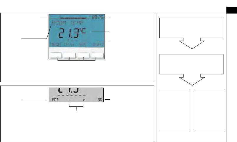
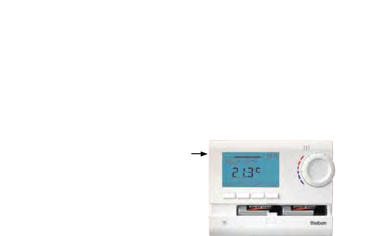
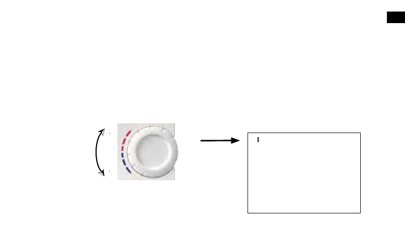
  • wat betekent het kleine vlammetje rechts boven de infoknop op de display ? Gesteld op 3-12-2017 om 12:31

    Reageer op deze vraag Misbruik melden
  • Enkele maanden geleden batterijen vervangen. Nu zegt de thermostaat soms dat de batterijen op zijn (flikkeren). Als ik batterijen verwijder en dezelfde batterijen er weer in stop werkt het weer. Hoe kan ik dit vermijden? Het vervelende is dat de ketel intussen urenlang gestookt heeft en dat we niet weten wat er kan gebeuren als we enkele uren of dagen uit huis zijn. Gesteld op 15-5-2017 om 09:28

    Reageer op deze vraag Misbruik melden
    • Ik heb het zelfde probleem en het blijkt een probleem van Theben te zijn.
      Bij de standaard nieuwe generatie van thermostaten gebeurt dit niet meer.
      Bij het laatste gesprek met Theben zijn zij er nooit meer op terug gekomen.
      Zo wij zitten nog steeds met het probleem. Geantwoord op 17-4-2018 om 08:56

      Waardeer dit antwoord Misbruik melden
  • Temperatuur bereikt op de thermostaat en het vlammetje is weg. De ketel slaat echter niet altijd af. Soms wel en soms niet. Ook bij het aanspringen blijft de cv lopen ook als de thermostaat zegt van niet. Het is niet altijd maar wel regelmatig. De ontvanger aan de cv krijgt niet altijd het signaal. Zou het helpen het antennetje te verlengen ? Gesteld op 6-2-2016 om 15:59

    Reageer op deze vraag Misbruik melden
    • Had het zelfde probleem. Bleek dat de ontvanger defect was. Kijk eens op de ontvanger indien het rode lichtje brandt wanneer de thermostaat geen temperatuur vraagt en de brander toch nog werkt. Indien ja zal er een probleem zijn met de ontvanger.
      Nieuwe batterijen in de thermostaat steken is ook een mogelijkheid. ( krachtiger signaal) Geantwoord op 8-2-2016 om 08:00

      Waardeer dit antwoord Misbruik melden
6
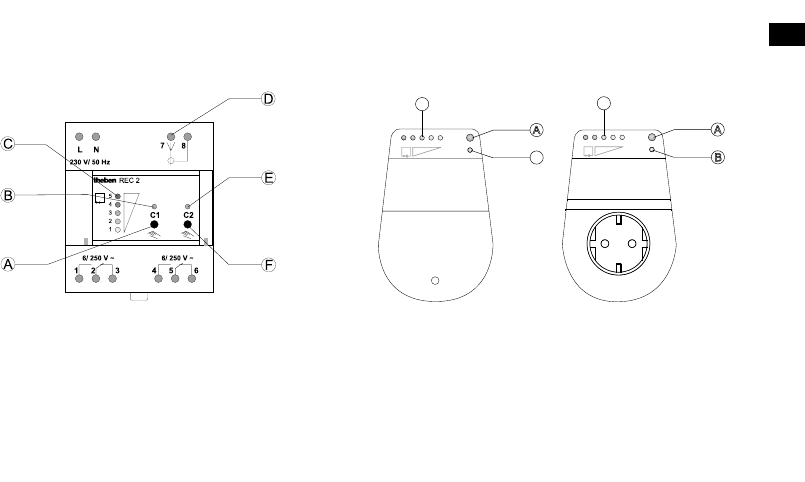
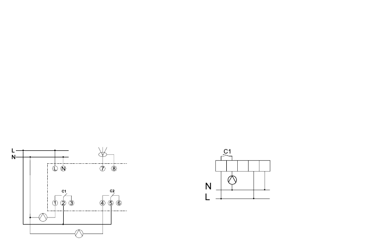
  • hoe sluit ik de ontvanger van een Ram813 top2hf set A juist aan? Ik veronderstel dat de klemmen 1 en 2 de stroomdraden zijn en de klemmen 4 en 5 de verbinding naar de brander zijn. Juist? Gesteld op 14-1-2016 om 07:34

    Reageer op deze vraag Misbruik melden
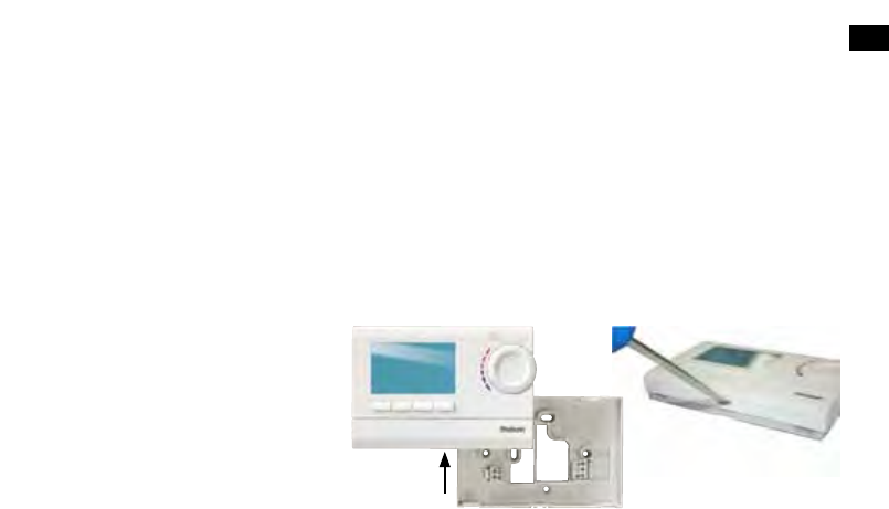
    • Als u een Ramses 813 top2 HF set A in uw bezit hebt, dan ziet u na het verwijderen van de beschermkap een klemmenstrook met 5 contacten.
      Van links naar rechts sluit u als volgt de bedrading aan:
      Op klem 1 sluit u de voeding van de brander aan. Dit is een fase (bruine draad)
      Op klem 2 sluit u de afgaande voeding - schakeldraad aan van de brander (zwarte draad)
      Op klem 4 sluit u de fase aan (bruine draad)
      Op klem 5 sluit u de nul aan (blauwe draad)

      Theben Nederland
      Geantwoord op 21-1-2016 om 09:05

      Waardeer dit antwoord (6) Misbruik melden

Misbruik melden

Gebruikershandleiding.com neemt misbruik van zijn services uitermate serieus. U kunt hieronder aangeven waarom deze vraag ongepast is. Wij controleren de vraag en zonodig wordt deze verwijderd.

Product:

Bijvoorbeeld antisemitische inhoud, racistische inhoud, of materiaal dat gewelddadige fysieke handelingen tot gevolg kan hebben.

Bijvoorbeeld een creditcardnummer, een persoonlijk identificatienummer, of een geheim adres. E-mailadressen en volledige namen worden niet als privégegevens beschouwd.

Spelregels forum

Om tot zinvolle vragen te komen hanteren wij de volgende spelregels:

Belangrijk! Als er een antwoord wordt gegeven op uw vraag, dan is het voor de gever van het antwoord nuttig om te weten als u er wel (of niet) mee geholpen bent! Wij vragen u dus ook te reageren op een antwoord.

Belangrijk! Antwoorden worden ook per e-mail naar abonnees gestuurd. Laat uw emailadres achter op deze site, zodat u op de hoogte blijft. U krijgt dan ook andere vragen en antwoorden te zien.

Abonneren

Abonneer u voor het ontvangen van emails voor uw Theben RAMSES 813 top2 HF bij:


U ontvangt een email met instructies om u voor één of beide opties in te schrijven.


Ontvang uw handleiding per email

Vul uw emailadres in en ontvang de handleiding van Theben RAMSES 813 top2 HF in de taal/talen: Engels als bijlage per email.

De handleiding is 0,88 mb groot.


U ontvangt de handleiding per email binnen enkele minuten. Als u geen email heeft ontvangen, dan heeft u waarschijnlijk een verkeerd emailadres ingevuld of is uw mailbox te vol. Daarnaast kan het zijn dat uw internetprovider een maximum heeft aan de grootte per email. Omdat hier een handleiding wordt meegestuurd, kan het voorkomen dat de email groter is dan toegestaan bij uw provider.

Stel vragen via chat aan uw handleiding

Stel uw vraag over deze PDF

Andere handleiding(en) van Theben RAMSES 813 top2 HF

Theben RAMSES 813 top2 HF Gebruiksaanwijzing - Nederlands - 38 pagina's

Theben RAMSES 813 top2 HF Gebruiksaanwijzing - Deutsch - 76 pagina's

Theben RAMSES 813 top2 HF Gebruiksaanwijzing - Français - 38 pagina's


Uw handleiding is per email verstuurd. Controleer uw email

Als u niet binnen een kwartier uw email met handleiding ontvangen heeft, kan het zijn dat u een verkeerd emailadres heeft ingevuld of dat uw emailprovider een maximum grootte per email heeft ingesteld die kleiner is dan de grootte van de handleiding.

Er is een email naar u verstuurd om uw inschrijving definitief te maken.

Controleer uw email en volg de aanwijzingen op om uw inschrijving definitief te maken

U heeft geen emailadres opgegeven

Als u de handleiding per email wilt ontvangen, vul dan een geldig emailadres in.

Uw vraag is op deze pagina toegevoegd

Wilt u een email ontvangen bij een antwoord en/of nieuwe vragen? Vul dan hier uw emailadres in.


Info