7
IMPORTANT INSTALLATION
SPECIFICATIONS
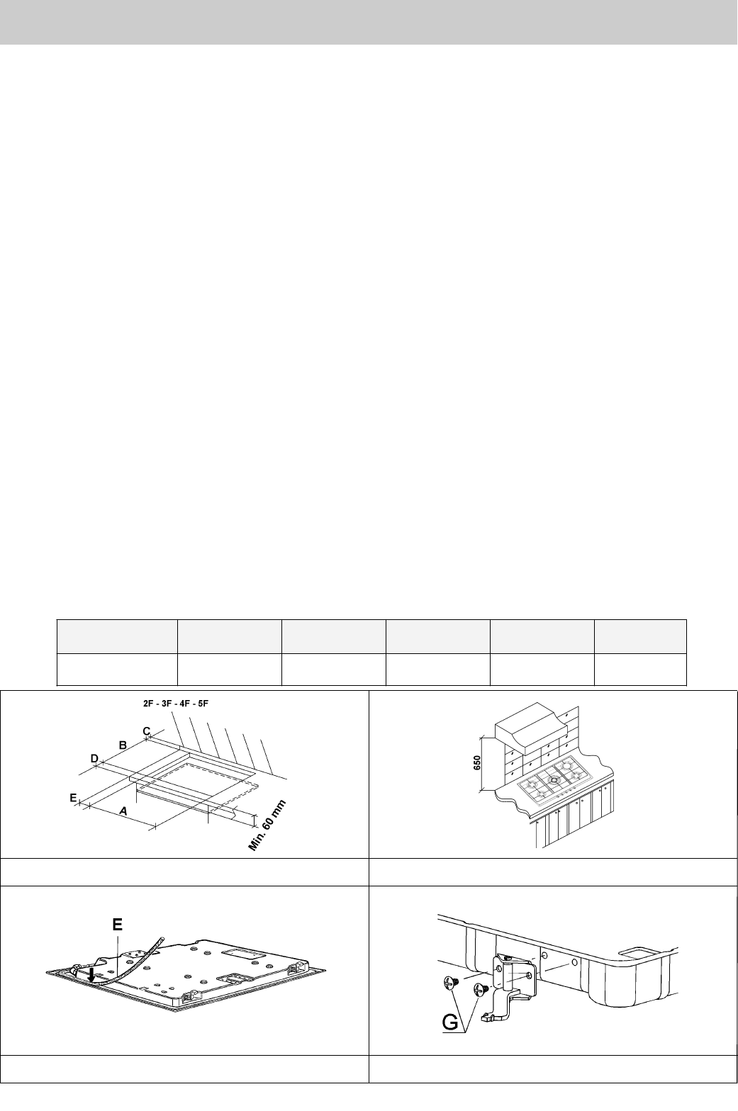
The installer should note that the appliance
that side walls should be no higher than the
hot plate itself. Furthermore, the rear wall, the
surfaces surrounding and adjacent to the
appliance must be able to withstand an
overtemperature of 75 K.
The adhesive used to stick the plastic laminate
to the cabinet must be able to withstand a
temperature of not less than 150° C otherwise
the laminate could come unstuck.
The appliance must be installed in compliance
with the provisions in force.
This appliance is not connected to a device
able to dispose of the combustion fumes. It
must therefore be connected in compliance
with the above mentioned installation
standards. Particular care should be paid to
the following provisions governing ventilation
and aeration.
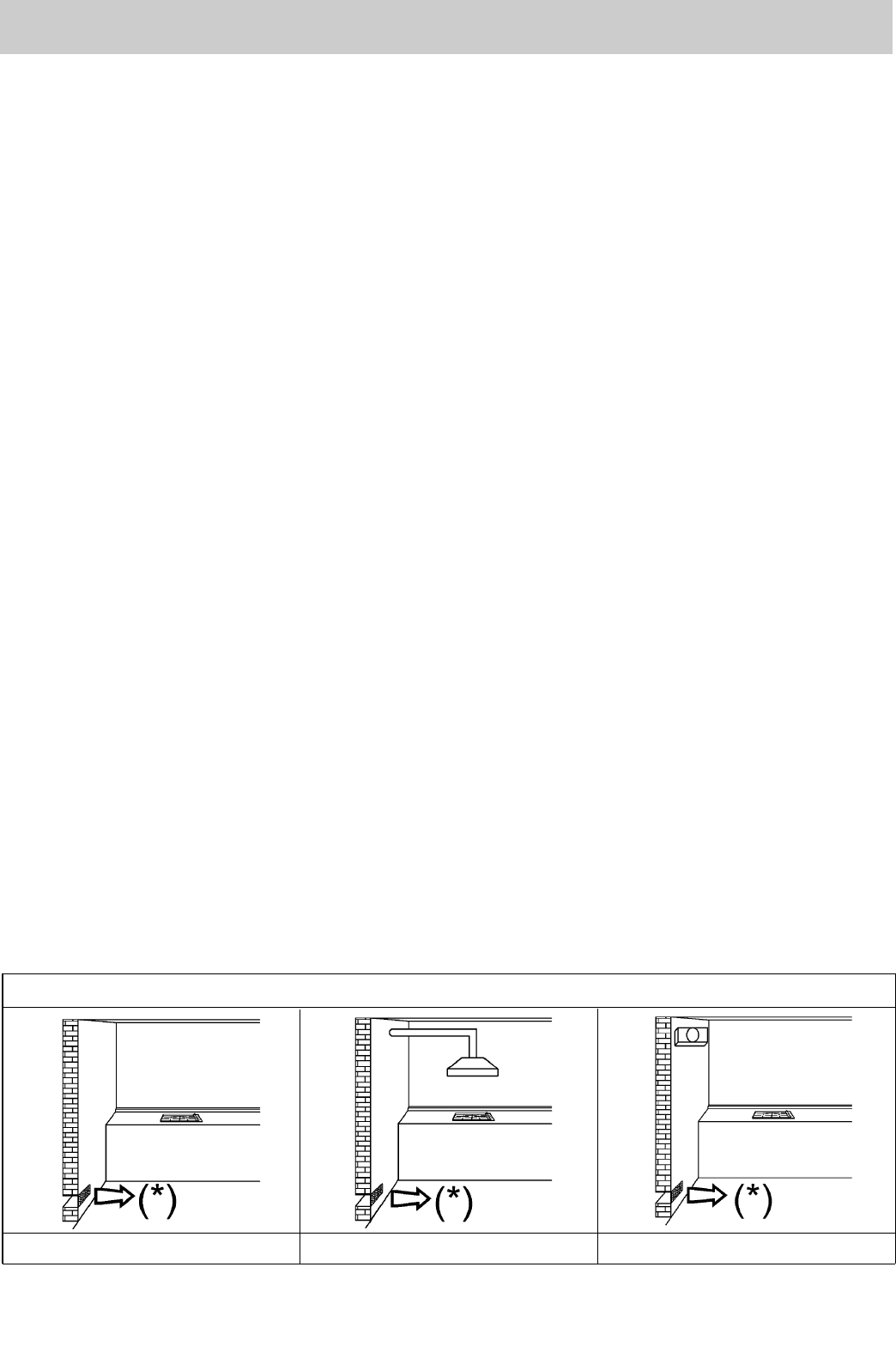
5) ROOM VENTILATION
It is essential to ensure that the room in which the
appliance is installed is permanently ventilated in
order to allow the appliance itself to operate correctly.
the necessary amount of air is that required for regular
gas combustion and ventilation of the relative room,
the volume of which must not be less than 20 m
3
. Air
must naturally flow through permanent openings in
the walls of the room in question. These openings
must vent the fumes outdoors and their section must
be at least 100 cm
2
(see fig. 3). Construction of the
openings must ensure that the openings themselves
may never be blocked. Indirect ventilation by air
drawn from an adjacent room is also permitted, in
strict compliance with the provisions in force.
CAUTION: if the burners of the cooking top are
without safety thermocouple, the ventilation
outlet must have a minimum 200 cm² section.
6) LOCATION AND AERATION
Gas cooking appliances must always dispose of their
combustion fumes through hoods. These must be
connected to flues, chimneys or straight outside. If it
is not possible to install a hood, an electric fan can be
installed on a window or on a wall facing outside (see
fig. 4). This must be activated at the same time as
the appliance (see fig. 5), so long as the
specifications in the provisions in force are strictly
complied with.
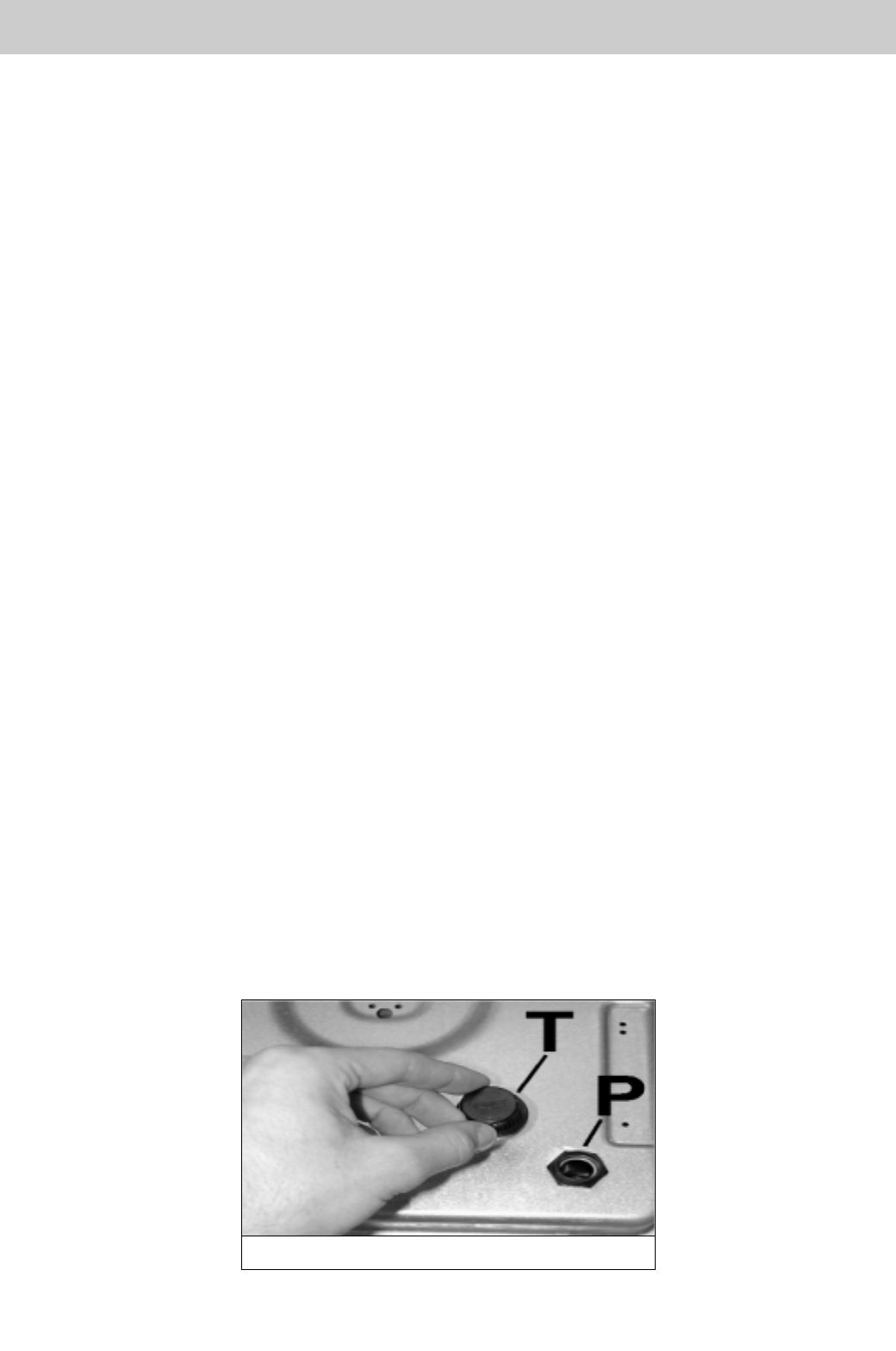
7) GAS CONNECTION
Before connecting the appliance, check that the
values on the data label affixed to the underside
of the hot plate correspond to those of the gas
and electricity mains in the home.
A label on the appliance indicates the regulating
conditions: type of gas and working pressure.
Gas connection must comply with the pertinent
standards and provisions in force.
When gas is supplied through ducts, the appliance
must be connected to the gas supply system:
o with a rigid steel pipe. The joints of this pipe must
consist of threaded fittings conforming to the
standards.
o With copper pipe. The joints of this pipe must consist
of unions with mechanical seals.
oWith seamless flexible stainless steel pipe. The
length of this pipe must be 2 meters at most and the
seals must comply with the standards.
When the gas is supplied by a bottle, the appliance
must be fuelled by a pressure governor conforming to
the provisions in force and must be connected:
owith a copper pipe. The joints of this pipe must
consist of unions with mechanical seals.
oWith seamless flexible stainless steel pipe. The
length of this pipe must be 2 meters at most and the
seals must comply with the standards. It is advisable
to apply the special adapter to the flexible pipe. This
is easily available from the shops and facilitates
connection with the hose nipple of the pressure
governor on the bottle.
o With rubber hose pipe in compliance with standards.
The diameter of this hose pipe must be 8 mm and its
length must be no less than 400 mm and no more
than 1500 mm. It must be firmly fixed to the hose
nipple by means of the safety clamp specified by
standards.
At the connection end, verify the gasproof using a
soap solution, never a flame.
WARNINGS:
- Remember that the gas inlet union on the
appliance is a 1/2" gas parallel male type in
compliance with ISO 228-1 standards.
- Installation of stainless steel pipe and rubber
hose pipe must ensure that it is never able to
touch mobile parts of the built-in cabinet (eg.
drawers). Furthermore, it must not pass
through compartments that could be used for
storage purposes.
- The appliance complies with the provisions of
the following EEC Directives:
90/396 + 93/68 regarding gas safety.
The installer should bear in mind that the mixed
appliance is the Y type. The rear wall, adjacent
and surrounding surfaces must therefore be able
to withstand an overtemperature of 75 K.
INSTALLATION