781219
27
Verklein
Vergroot
Pagina terug
1/41
Pagina verder
INSTALLATION INSTRUCTIONS
AND RECOMMENDATIONS FOR USE AND MAINTENANCE
GLASS GAS HOBS
INSTRUCCIONES PARA LA INSTALACIÓN
Y RECOMENDACIONES DE USO Y MANTENIMIENTO
COCINAS CRISTAL GAS
GB_61401134_en.qxd 05.03.2015 11:11 Page 1
P20995R05
HF LUX 60 4G AL NAT / HF LUX 60 4G AL BUT
HF LUX 50 4G AL NAT / HF LUX 50 4G AL BUT
HLX 60 4G AL NAT / HLX 60 4G AL BUT
HF LUX 50 4G Al AL CI NAT / HF LUX 50 4G Al AL CI BUT
HF LUX 60 AI AL CI NAT / HF LUX 60 AI AL CI BUT
Contents / Índice
Introduction
User Guide
Installation
Positioning the hobs
Positioning the oven
Anchoring the hob
Connecting the gas
Connecting the electricity
Gas conversion
Technical information
Dimensions and powers
Technical data
Use and Maintenance
Elements of a burner
Igniting the burners
Anti-accidental turn mechanism
on the gas controls
Safety sistem components
Maintenance of the glass
Suggestions for effective use
the burners
Maintenance of the burners
Environmental considerations
Reminder
Cleaning and care
If something doesn’t work
Page 3
4-5
6
6
7
7-8
8
9
11
12
12
13
14
14
14-15
15
15
16
16-17
17
17
18
19
20
GB
Presentación
Guía de Uso
Instalación
Emplazamiento de las encimeras
de cocción
Emplazamiento del horno
Anclaje de la encimera de cocción
Conexión del gas
Conexión eléctrica
Transformación del gas
Información técnica
Dimensiones y potencias
Datos técnicos
Uso y Mantenimiento
Elementos de un quemador
Encendido de los quemadores
Sistema antigiro accidental en
mandos de gas
Componentes de un sistema
con seguridad
Mantenimiento de los quemadores
Consejos para la buena
conservación del vidrio
Consejos para la buena utilización
de los quemadores
Consideraciones medioambientales
Recuerde
Limpieza y conservación
Si algo no funciona
Página 3
21-22-23
24
24
25
25-26
26
26-27
29
30
30
31
32
32
32-33
33
33
33-34
34
35
35-36
37
38
39
ES
GB_61401134_en.qxd 05.03.2015 11:11 Page 2
1
Introduction / Presentación
HF LUX 60 4G AL BUT
HF LUX 60 4G AL NAT
HF LUX 60 AI AL CI NAT
HF LUX 60 AI AL CI BUT
1 Semi-rapid burner 1,500 Kcal/h -1.75 kW.
2 Semi-rapid burner 1,500 Kcal/h -1.75 kW.
3 Rapid burner 2,850 Kcal/h -3.00 kW.
4 Auxiliary burner 860 Kcal/h - 1 kW.
5 Burner operating controls.
* All the burners have a grid.
* Maximum calorific power: 6,450 Kcal/h - 7.5 kW.
1 Quemador semi-rápido de 1.500 Kcal/h - 1.75 kW.
2 Quemador semi-rápido de 1.500 Kcal/h - 1.75 kW.
3 Quemadorpido de 2.580 Kcal/h - 3.00 kW.
4 Quemador auxiliar de 860 Kcal/h - 1 kW.
5 Mandos de accionamiento de los quemadores.
* Todos los quemadores llevan parrilla.
* Potencia caloríficaxima: 6.450 Kcal/h - 7.5 kW.
HF LUX 50 4G Al AL CI NAT
HF LUX 50 4G Al AL CI BUT
HF LUX 50 4G AL BUT
HF LUX 50 4G AL NAT
1 Semi-rapid burner 1,500 Kcal/h -1.75 kW.
2 Semi-rapid burner 1,500 Kcal/h -1.75 kW.
3 Rapid burner 2,850 Kcal/h -3.00 kW.
4 Auxiliary burner 860 Kcal/h - 1 kW.
5 Burner operating controls.
* All the burners have a grid.
* Maximum calorific power: 6,450 Kcal/h - 7.5 kW.
1 Quemador semi-rápido de 1.500 Kcal/h - 1.75 kW.
2 Quemador semi-rápido de 1.500 Kcal/h - 1.75 kW.
3 Quemadorpido de 2.580 Kcal/h - 3.00 kW.
4 Quemador auxiliar de 860 Kcal/h - 1 kW.
5 Mandos de accionamiento de los quemadores.
* Todos los quemadores llevan parrilla.
* Potencia caloríficaxima: 6.450 Kcal/h - 7.5 kW.
GB
GB
5
2
34
12
34
1
ES
ES
HLX 60 4G AL BUT
HLX 60 4G AL NAT
1 Semi-rapid burner 1,500 Kcal/h -1.75 kW.
2 Semi-rapid burner 1,500 Kcal/h -1.75 kW.
3 Rapid burner 2,850 Kcal/h -3.00 kW.
4 Auxiliary burner 860 Kcal/h - 1 kW.
5 Burner operating controls.
* All the burners have a grid.
* Maximum calorific power: 6,450 Kcal/h - 7.5 kW.
1 Quemador semi-rápido de 1.500 Kcal/h - 1.75 kW.
2 Quemador semi-rápido de 1.500 Kcal/h - 1.75 kW.
3 Quemadorpido de 2.580 Kcal/h - 3.00 kW.
4 Quemador auxiliar de 860 Kcal/h - 1 kW.
5 Mandos de accionamiento de los quemadores.
* Todos los quemadores llevan parrilla.
* Potencia caloríficaxima: 6.450 Kcal/h - 7.5 kW.
GB
ES
GB_61401134_en.qxd 05.03.2015 11:11 Page 3
5
2
Guide to Using the Instructions Booklet
Dear customer,
We are delighted that you have put your
trust in us.
We are confident that the new hob that you
have purchased will fully satisfy your
needs.
This modern, functional and practical
model has been manufactured using top-
quality materials that have undergone
strict quality controls throughout the manu-
facturing process.
Before installing and using it, we would
ask that you read this Manual carefully and
follow the instructions closely, as this will
guarantee better results when using the
appliance.
Keep this Instruction Manual in a safe
place so that you can refer to it easily and
thus abide by the guarantee conditions.
In order to benefit from this Guarantee, it is
essential that you submit the purchase
receipt together with the Guarantee Certi-
ficate.
You should keep the Guarantee
Certificate or, where relevant, the
technical datasheet, together with the
Instruction Manual for the duration of
the useful life of the appliance. It has
important technical information about
the appliance.
Safety instructions
Before first use, you should carefully read
the installation and connection instruc-
tions.
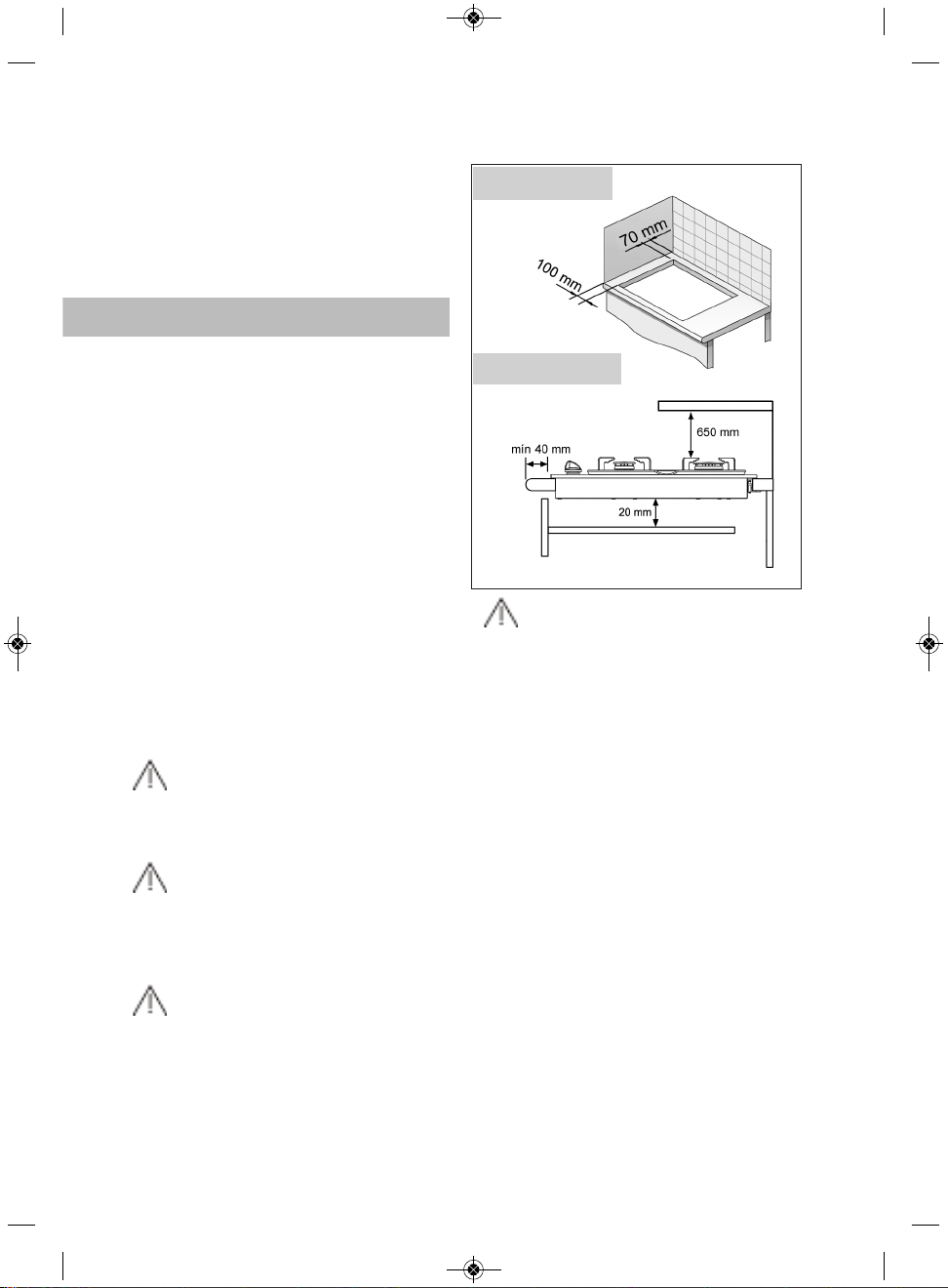
These hob models may be installed in the
same kitchen furniture units as TEKA
brand ovens.
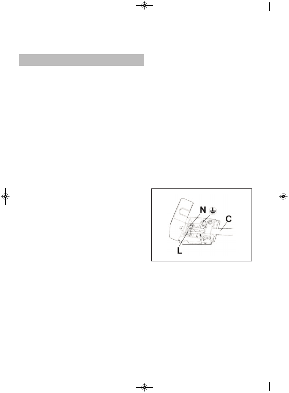
For your safety, installation should be
carried out by an authorised technician
and should comply with existing installa-
tion standards. Likewise, any internal work
on the hob should only be done by TEKAs
technical staff, including the change of the
flexible supply cable of the appliance.
Safety warnings:
If the glass breaks or
cracks, the hob should imme-
diately be disconnected from
electric current in order to
avoid the risk of electric
shock and all burners should
immediately be switched off.
Appliance surface shouldn't
be touched and used.
This appliance is not
designed to work with an
external timer (not built into
the appliance) or a separate
remote control system.
The device and its acces-
sible parts may heat up
during operation. Avoid tou-
ching the heating elements.
Children younger than 8
years old must stay away
from the stovetop unless
they are permanently super-
vised.
This device may solely
be used by children 8 years
old or older, people with
impaired physical, sensory or
mental abilities, or those who
lack experience and knowled-
ge, ONLY when supervised or
if they have been given ade-
quate instruction on the use
GB_61401134_en.qxd 27.02.2015 14:52 Page 4
3
of the device and understand
the dangers its use involves.
User cleaning and mainte-
nance may not be done by
unsupervised children.
Children must not play
with the device.
Precaution. It is dange-
rous to cook with fat or oil
without being present, as
these may catch fire. Never
try to extinguish a fire with
water! in this event discon-
nect the device and cover the
flames with a lid, a plate or a
blanket.
Do not store any object
on the cooking areas of the
stovetop. Prevent a possible
fire hazard.
For safety reasons, we
advise that the instructions
provided by the gas supply
company are followed and
that the supply tap is turned
off when the hob is not in use.
If a gas smell is noted,
the gas intake to the hob
should be shut off and the
room ventilated. The gas ins-
tallation and the hob should
also be checked by a specia-
lised technician.
In the event of the burner
flames being accidentally
extinguished, turn off the bur-
ner control and do not
attempt to re-ignite the burner
for at least one minute.
This appliance must be
used exclusively for cooking,
never for other purposes
such as heating a room.
TEKA doesn't recom-
mend the use of protective
covers for cooktops. The use
of inadequate protective
covers can cause accidents.
Steam cleaner should not
be used.
GB_61401134_en.qxd 27.02.2015 14:52 Page 5
4
Important
INSTALLATION AND SETUP SHOULD
BE CARRIED OUT BY AN AUTHORISED
TECHNICIAN IN LINE WITH CURRENT
INSTALLATION STANDARDS.
Positioning the hobs
Depending on the model to be installed, an
opening with the dimensions shown in
figure 2 will be cut into the unit’s worktop or
stove.
The system for fixing the hob is intended
for use with kitchen units with a thickness
of 20, 30 and 40 mm.
The minimum distance between the surfa-
ce supporting the cooking pans and the
lower part of the kitchen unit or the hood
located above the hob should be 650 mm.
If the hood’s installation instructions
recommend that the gap is greater than
this, you should follow this advice.
The unit where the hob and oven will be
located will be suitably fixed.
Warnings:
When hobs are handled before
being installed, care should be taken in
case there is any protruding part or
sharp edge which could cause injury.
When installing units or applian-
ces above the hob, the hob should be
protected by a board so that the glass
cannot be damaged by accidental
blows or heavy weights.
The glues used in manufacturing
the kitchen unit and in the adhesive on
the decorative laminate of the worktop
surface should be made to tolerate tem-
peratures of up to 100ºC.
TEKA assumes no responsibility
for any malfunction or damage caused
by faulty installation.
Installation
GB_61401134_en.qxd 27.02.2015 14:52 Page 6
fig. 1
Minimum distances
to walls
Minimum ventilation
distances
5
PLEASE REMEMBER THAT THE GUA-
RANTEE DOES NOT COVER THE
GLASS IF IT SUFFERS A VIOLENT
BLOW OR IF IT IS USED IMPROPERLY.
Positioning the oven
See the corresponding manual.
Anchoring the hob
When the gap has been properly sized, the
sealing washer should be put on the lower
face of the glass. Silicone should not be
applied between the glass and the unit
worktop because if it becomes neces-
sary to remove the hob from its position,
the glass could break when trying to
detach it.
To secure the hob to the cabinet, four brac-
kets should be fastened to the existing holes
on the bottom part of the casing (two in the
front and two in the back). There are two
possibilities of where the brackets may be
placed, just as is shown in figure 3.
Depending on the thickness of the cabinet, it
may be necessary to use the self tapping
screws that are provided as compliments for
securing; insert them in the circular holes of
the bracket. The thread of this hole will be
made when the screw is inserted inside of it.
The thread should be made before faste-
ning the bracket to the hob.
Hob is mounted by inserting the quick nuts
into the holes where the screws go (see
fig. 5) and then attaching the appropriate
clip, depending on the worktop’s thickness
(20, 30 and 40 mm) and tightening the
screws until it is firmly fastened.
If an oven is being installed beneath the
hob, avoid the power cable coming into
contact with very hot components.
fig. 3
Sealing washer
Sealing washer
GB_61401134_en.qxd 27.02.2015 14:52 Page 7
fig. 2
575 max.
L
Fitting holes
The dimensions L and W are shown in the table
"Dimensions and characteristics" of the Technical
Information section.
W
6
Connecting the Gas
Connecting the hob to the gas mains
should be done in compliance with the
current installation standards and/or regu-
lations, and by a qualified technician (an
authorised installing engineer). The gas
connection for these hotplates should be
made with rigid piping, because the
appliance is a stationery one, where it is
destined for the EC market. The hob has a
threaded connection of 1/2’ in diameter
(as per EN ISO 228-1 ) or 1/2’’ with a coni-
cal thread (as per EN 10226-1), depending
on the regulations in the destination
country.
For markets with an EN ISO 228-1 1/2’’
connection, a 10/12 mm copper pipe is
provided as an accessory for welding to
the gas intake pipe.
Ventilation slots should also be made at
the site in compliance with current norms.
Connecting the hob’s gas intake to the
mains should be done in compliance with
the basic gas installation standards for
residential premises.
TEKA assumes no responsibility for any
malfunction or damage that arises from an
incorrect or faulty installation.
In order that the hob is not damaged by
tightening the nut on the gas connection
pipe, a maximum torque of 300 cm * Kgf
should be applied.
When the gas connection has been made,
the installation should be checked to ensu-
re that it is completely sealed. If the check
is done using air, care should be taken that
the test pressure is no more than 200
g/cm² Where air is not available, soapy
water should be applied to ensure that
there are no leaks in the connections. Tes-
ting should never be done using a
flame.
When the hob has been installed, check
that the burner minimums are properly
adjusted. To do this, light the burners and
check that they do not go out if you switch
quickly from the maximum to the minimum.
Whenever the gas connection nut is remo-
ved, its washer should be changed.
fig. 4
Sealing washer
Sealing washer
GB_61401134_en.qxd 27.02.2015 14:52 Page 8
fig. 5
Sealing washer
Worktop
Screw
Fixing clip
Rapid screw
7
Connecting the Electricity
(Only hobs with automatic ignition or elec-
tric hotplates)
Before connecting the hob to the electric
mains, check that the voltage and fre-
quency of the mains matches what is
shown on the hob’s rating plate, which is
located lower down, and on the guarantee
certificate or, where appropriate, the tech-
nical datasheet supplied, which should be
kept together with this manual.
When the appliance is connected to the
electricity main by a socket:
* Fit a standard plug suited to the load indi-
cated on the data label to the cable. Fit the
wires following figure 6, taking care of res-
pecting the following correspondences:
Letter L (live) = brown wire;
Letter N (neutral) = blue wire;
Earth symbol = green - yellow wire.
* The power supply cable must be positio-
ned so that no part of it is able to reach an
overtemperature of 65 K.
* Never use reductions, adapters of shunts
for connection since these could create
false contacts and lead to dangerous over-
heating.
The connection is made via an omnipolar
switch or plug where accessible, which is
suitable for the intensity to be tolerated
and which has a minimum gap of 3 mm
between its contacts, which will ensure
disconnection in case of emergency or
when cleaning the hob. It should also be
correctly earthed in line with current stan-
dards.
The connection should include correct
earthing, in compliance with current
norms.
If the flexible supply cable fitted to these
appliances ever needs to be changed, it
should be replaced by TEKAs official service.
Need to allow the disconnection of the
network device after installation, via a
plug or switch accessible.
All our appliances are designed and
manufactured in compliance with Euro-
pean standards EN 60 335-1 and EN 60
335-2-6 plus the relative
amendments.
The appliance complies with the provi-
sions of the following EEC Directives:
- 2004/108/EC regarding to
electromagnetic compatibility.
- 2006/95/EC regarding electrical safety.
fig. 6
GB_61401134_en.qxd 27.02.2015 14:52 Page 9
If the mains cord is damaged, should
be replaced by the manufacturer or its
after sales service.
8
TR_61401134_en.qxd 13.10.2014 16:17 Page 11
9
CABLE CONNECTION SCHEME
a la red eléctrica, compruebe que la ten-
sión (voltaje) y la frecuencia de aquella
corresponden con las indicadas en la
placa de características de la encimera, la
cual está situada en su parte inferior y en
la hoja de garantía o, en su caso, la hoja
de datos técnicos adjunta que debe de
conservar junto a este manual.
Cuando el aparato se conecta a la corrien-
te eléctrica mediante un enchufe:
Aplique un enchufe normalizado adecua-
do para la carga indicada en la etiqueta de
identificación. Conecte los cables según la
figura 6, prestando atención de respetar
las siguientes correspondencias:
Letra L (fase) = cable de color marrón;
Letra N (neutro) = cable de color azul;
Símbolo tierra = cable de color verde-ama-
rillo
El cable de alimentación debe colocarse
de manera que no alcance en ningún
punto una temperatura de 65K.
Nunca utilice reducciones, adaptadores o
derivadores para efectuar la conexión
puesto para efectuar la conexión puesto
que podrían provocar falsos contactos y
peligrosos sobrecalentamientos.
La conexión se realizará a través de un
interruptor de corte omnipolar o clavija
siempre que sea accesible, adecuado a la
intensidad a soportar y con una apertura
mínima entre contactos de 3 mm., que
asegure la desconexión para casos de
emergencia o limpieza de la encimera. La
conexión debe realizarse con una correcta
toma de tierra, siguiendo la normativa
vigente.
La conexión debe realizarse con una
correcta toma de tierra, en cumplimiento
con la normativa vigente
Cualquier manipulación o reparación del
aparato, incluida la sustitución del cable
flexible de alimentación, deberá ser reali-
zada por el servicio técnico oficial de
TEKA.
La toma debe quedar accesible después
de efectuar el encastre, a través de enchu-
fe o interruptor accesibles.
ADVERTENCIA.
Todos nuestros aparatos han sido diseña-
dos y fabricados según las normas euro-
peas EN 60 335-1, EN 60 335-2-6 y EN 60
335-2-102 y sus relativas enmiendas.
El aparato cumple las disposiciones de las
Directivas Europeas:
CEE 2004/108/CE relativa a la compatibi-
lidad electromagnética
CEE 2006/95 relativa a la seguridad eléc-
trica.
ES_Maquetación 1 05.03.2015 11:33 Page 9
fig. 6
Si el cable de alimentación está dañado,
debe ser sustituido por el fabricante o
su servicio posventa
26
27

Hulp nodig? Stel uw vraag in het forum

Spelregels

Misbruik melden

Gebruikershandleiding.com neemt misbruik van zijn services uitermate serieus. U kunt hieronder aangeven waarom deze vraag ongepast is. Wij controleren de vraag en zonodig wordt deze verwijderd.

Product:

Bijvoorbeeld antisemitische inhoud, racistische inhoud, of materiaal dat gewelddadige fysieke handelingen tot gevolg kan hebben.

Bijvoorbeeld een creditcardnummer, een persoonlijk identificatienummer, of een geheim adres. E-mailadressen en volledige namen worden niet als privégegevens beschouwd.

Spelregels forum

Om tot zinvolle vragen te komen hanteren wij de volgende spelregels:

Belangrijk! Als er een antwoord wordt gegeven op uw vraag, dan is het voor de gever van het antwoord nuttig om te weten als u er wel (of niet) mee geholpen bent! Wij vragen u dus ook te reageren op een antwoord.

Belangrijk! Antwoorden worden ook per e-mail naar abonnees gestuurd. Laat uw emailadres achter op deze site, zodat u op de hoogte blijft. U krijgt dan ook andere vragen en antwoorden te zien.

Abonneren

Abonneer u voor het ontvangen van emails voor uw Teka HLX 60 bij:


U ontvangt een email met instructies om u voor één of beide opties in te schrijven.


Ontvang uw handleiding per email

Vul uw emailadres in en ontvang de handleiding van Teka HLX 60 in de taal/talen: Engels, Spaans als bijlage per email.

De handleiding is 5.18 mb groot.


U ontvangt de handleiding per email binnen enkele minuten. Als u geen email heeft ontvangen, dan heeft u waarschijnlijk een verkeerd emailadres ingevuld of is uw mailbox te vol. Daarnaast kan het zijn dat uw internetprovider een maximum heeft aan de grootte per email. Omdat hier een handleiding wordt meegestuurd, kan het voorkomen dat de email groter is dan toegestaan bij uw provider.

Stel vragen via chat aan uw handleiding

Stel uw vraag over deze PDF

Uw handleiding is per email verstuurd. Controleer uw email

Als u niet binnen een kwartier uw email met handleiding ontvangen heeft, kan het zijn dat u een verkeerd emailadres heeft ingevuld of dat uw emailprovider een maximum grootte per email heeft ingesteld die kleiner is dan de grootte van de handleiding.

Er is een email naar u verstuurd om uw inschrijving definitief te maken.

Controleer uw email en volg de aanwijzingen op om uw inschrijving definitief te maken

U heeft geen emailadres opgegeven

Als u de handleiding per email wilt ontvangen, vul dan een geldig emailadres in.

Uw vraag is op deze pagina toegevoegd

Wilt u een email ontvangen bij een antwoord en/of nieuwe vragen? Vul dan hier uw emailadres in.


Info