3
RQT6252
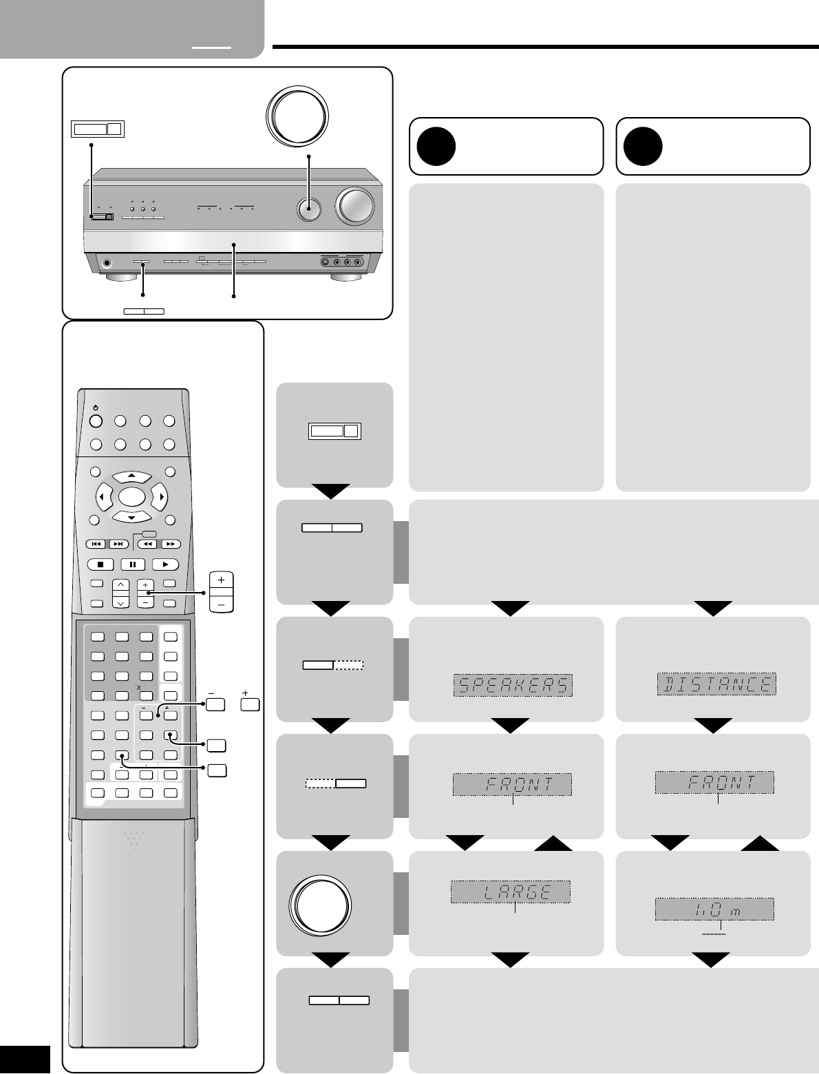
Step 1
Step 2
Step 3
Step 4
Before use
Others
Reference
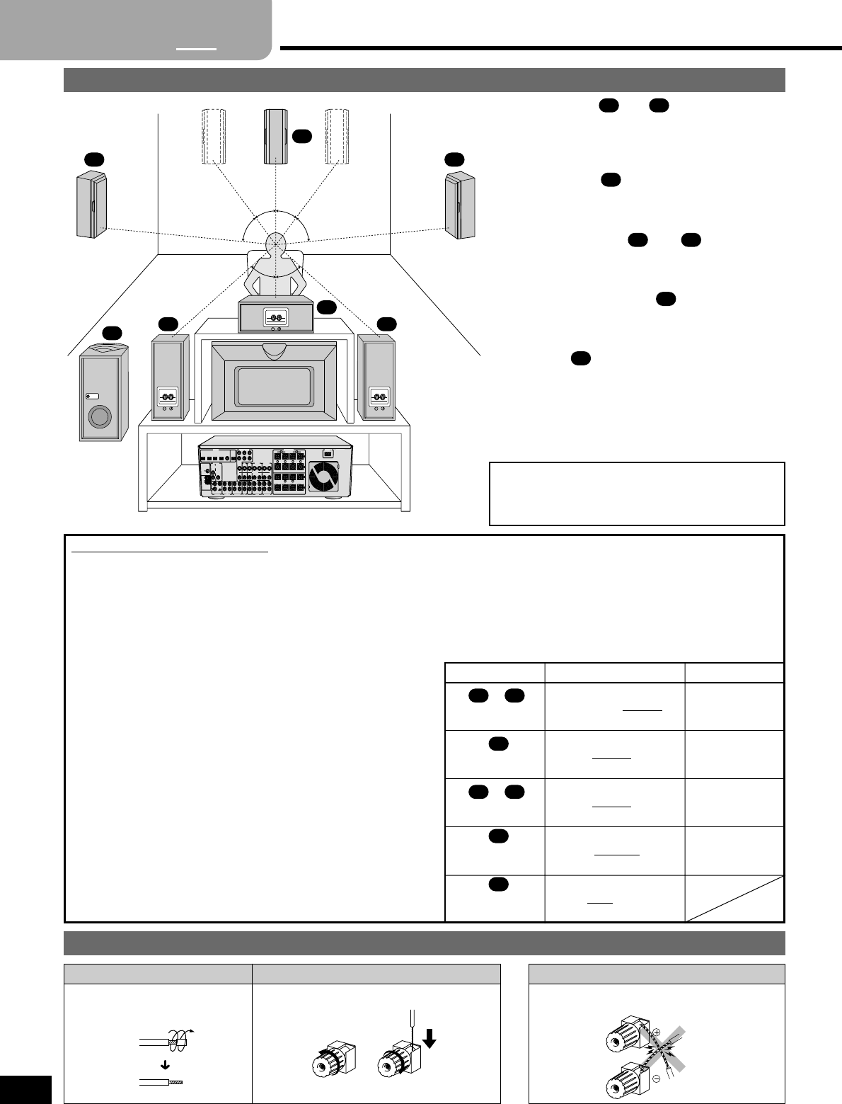
CAUTION!
¡DO NOT INSTALL, OR PLACE THIS UNIT, IN A
BOOKCASE, BUILT-IN CABINET OR IN ANOTHER
CONFINED SPACE. ENSURE THE UNIT IS WELL
VENTILATED. TO PREVENT RISK OF ELECTRIC SHOCK
OR FIRE HAZARD DUE TO OVERHEATING, ENSURE
THAT CURTAINS AND ANY OTHER MATERIALS DO NOT
OBSTRUCT THE VENTILATION VENTS.
¡DO NOT OBSTRUCT THE UNIT’S VENTILATION
OPENINGS WITH NEWSPAPERS, TABLECLOTHS,
CURTAINS, AND SIMILAR ITEMS.
¡DO NOT PLACE SOURCES OF NAKED FLAMES, SUCH
AS LIGHTED CANDLES, ON THE UNIT.
¡DISPOSE OF BATTERIES IN AN ENVIRONMENTALLY
FRIENDLY MANNER.
WARNING:
TO REDUCE THE RISK OF FIRE, ELECTRIC SHOCK OR
PRODUCT DAMAGE, DO NOT EXPOSE THIS APPARATUS
TO RAIN, MOISTURE, DRIPPING OR SPLASHING AND
THAT NO OBJECTS FILLED WITH LIQUIDS, SUCH AS
VASES, SHALL BE PLACED ON THE APPARATUS.
VAROITUS!
¡ÄLÄ ASENNA TAI LAITA TÄTÄ LAITETTA
KABINETTITYYPPISEEN KIRJAKAAPPIIN TAI MUUHUN
SULJETTUUN TILAAN, JOTTA TUULETUS ONNISTUISI.
VARMISTA, ETTÄ VERHO TAI MIKÄÄN MUU MATERIAALI
EI HUONONNA TUULETUSTA, JOTTA VÄLTETTÄISIIN
YLIKUUMENEMISESTA JOHTUVA SÄHKÖISKU- TAI
TULIPALOVAARA.
¡¡
ÄLÄ PEITÄ LAITTEEN TUULETUSAUKKOJA
SANOMALEHDELLÄ, PÖYTÄLIINALLA, VERHOLLA TAI
MUULLA VASTAAVALLA ESINEELLÄ.
¡¡
ÄLÄ ASETA PALAVAA KYNTTILÄÄ TAI MUUTA
AVOTULEN LÄHDETTÄ LAITTEEN PÄÄLLE.
¡¡
HÄVITÄ PARISTOT LUONTOA
VAHINGOITTAMATTOMALLA TAVALLA.
SUOMI
VAROITUS:
TULIPALO-, SÄHKÖISKUVAARAN TAI TUOTETTA
KOHTAAVAN MUUN VAHINGON VÄHENTÄMISEKSI EI
LAITETTA SAA ALTISTAA SATEELLE, KOSTEUDELLE,
VESIPISAROILLE TAI ROISKEELLE, EIKÄ NESTETTÄ
SISÄLTÄVIÄ ESINEITÄ, KUTEN ESIMERKIKSI
MALJAKOITA, SAA ASETTAA LAITTEEN PÄÄLLE.
ADVARSEL!
¡¡
APPARATET MÅ IKKE PLASSERES I EN BOKHYLLE, ET
INNEBYGGET KABINETT ELLER ET ANNET LUKKET
STED HVOR VENTILASJONSFORHOLDENE ER
UTILSTREKKELIGE. SØRG FOR AT GARDINER ELLER
LIGNENDE IKKE FORVERRER
VENTILASJONSFORHOLDENE, SÅ RISIKO FOR
ELEKTRISK SJOKK ELLER BRANN FORÅRSAKET AV
OVERHETING UNNGÅS.
¡¡
APPARATETS VENTILASJONSÅPNINGER MÅ IKKE
DEKKES TIL MED AVISER, BORDDUKER, GARDINER OG
LIGNENDE.
¡¡
PLASSER IKKE ÅPEN ILD, SLIK SOM LEVENDE LYS,
OPPÅ APPARATET.
¡¡
BRUKTE BATTERIER MÅ KASSERES UTEN FARE FOR
MILJØET.
NORSK
ADVARSEL:
FOR Å REDUSERE FAREN FOR BRANN, ELEKTRISK STØT
ELLER SKADER PÅ PRODUKTET, MÅ DETTE APPARATET
IKKE UTSETTES FOR REGN, FUKTIGHET, VANNDRÅPER
ELLER VANNSPRUT. DET MÅ HELLER IKKE PLASSERES
GJENSTANDER FYLT MED VANN, SLIK SOM
BLOMSTERVASER, OPPÅ APPARATET.
THIS UNIT IS INTENDED FOR USE IN MODERATE
CLIMATES.
TÄMÄ LAITE ON TARKOITETTU KÄYTETTÄVÄKSI
LEUDOSSA ILMASTOSSA.
DETTE APPARATET ER BEREGNET TIL BRUK UNDER
MODERATE KLIMAFORHOLD.
This product may receive radio interference caused by mobile
telephones during use. If such interference is apparent, please
increase separation between the product and the mobile
telephone.
CAUTION
Do not place anything on top of this unit or block the heat
radiation vents in any way. In particular, do not place tape decks
or CD/DVD players on this unit as heat radiated from it can
damage your software.
www.panasonic.co.uk (for UK customers only)
¡Order accessory and consumable items for your product
with ease and confidence by telephoning our
Customer Care Centre Mon-Friday 9:00am-5:30pm.
(Excluding public holidays.)
¡Or go on line through our Internet Accessory ordering
application.
¡Most major credit and debit cards accepted.
¡All enquiries transactions and distribution facilities are
provided directly by Panasonic UK Ltd.
¡It couldn’t be simpler!
Customer Care Centre
For UK customers: 08705 357357
For Republic of Ireland customers: 01 289 8333
Technical Support
For UK customers: 0870 1 505610
This Technical Support Hot Line number is for Panasonic
PC software related products only.
For Republic of Ireland, please use the Customer Care
Centre number listed above for all enquiries.
For all other product related enquiries, please use the
Customer Care Centre numbers listed above.
For the United Kingdom and Republic of Ireland