FS 240, FS 240 R
español / EE.UU
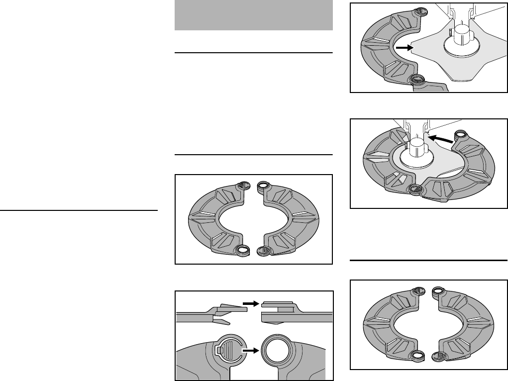
116
El sistema de control de emisiones de
su máquina incluye piezas tales como el
carburador y el sistema de encendido.
Además puede incluir mangueras,
conectores y otros conjuntos relativos a
emisiones.
En los casos de existir una condición
amparada bajo garantía, STIHL
Incorporated reparará el motor pequeño
para equipo de uso fuera de carretera
sin costo alguno, incluido el diagnóstico
(si el trabajo de diagnóstico fue
realizado por un concesionario
autorizado), las piezas y la mano de
obra.
Cobertura de garantía del fabricante
En los EE.UU., los motores pequeños
para equipos de uso fuera de carretera
modelos 1997 y posteriores también
están garantizados por dos años. En el
caso de encontrarse defectos en
cualquiera de las piezas del motor
relacionadas con el sistema de control
de emisiones, la pieza será reparada o
sustituida por STIHL Incorporated sin
costo alguno.
Responsabilidades del propietario
relativas a la garantía
Como propietario de motor pequeño
para equipo de uso fuera de carretera,
usted tiene la responsabilidad de
realizar el mantenimiento requerido
descrito en su manual de instrucciones.
STIHL Incorporated le recomienda
guardar todos los recibos comprobantes
de los trabajos de mantenimiento
hechos a su motor pequeño para equipo
de uso fuera de carretera, pero STIHL
Incorporated no puede negar garantía
basado en el solo hecho de faltar los
recibos o del incumplimiento del
propietario de realizar todos los trabajos
de mantenimiento programados.
El uso de cualquier pieza de repuesto o
servicio cuyo comportamiento y
durabilidad sean equivalentes está
permitido en trabajos de mantenimiento
o reparación no contemplados en la
garantía, y no reducirá las obligaciones
de la garantía del fabricante del motor.
Sin embargo, como propietario del
motor pequeño para equipo de uso
fuera de carretera usted debe ser
consciente de que STIHL Incorporated
puede negarle cobertura de garantía si
dicho motor o una pieza del mismo ha
fallado debido a maltrato, descuido,
mantenimiento inadecuado o
modificaciones no autorizadas.
Usted es responsable de llevar el motor
pequeño para equipo de uso fuera de
carretera a un centro de servicio STIHL
tan pronto surja el problema. Las
reparaciones bajo garantía serán
realizadas en un tiempo razonable, sin
exceder de 30 días.
Ante cualquier duda respecto a sus
derechos y responsabilidades bajo esta
garantía, sírvase contactar al
representante de atención al cliente
STIHL llamando al 1-800-467-8445, o si
lo prefiere puede escribir a
STIHL Inc.,
536 Viking Drive, P.O. Box 2015,
Virginia Beach, VA 23450-2015 EE.UU.
www.stihlusa.com
Cobertura por STIHL Incorporated
STIHL Incorporated garantiza al último
comprador y a cada comprador
subsiguiente que el motor pequeño para
equipo de uso fuera de carretera está
diseñado, construido y equipado, al
tiempo de la venta, de conformidad con
todos los reglamentos acerca de
emisiones aplicables. Además, STIHL
Incorporated garantiza al comprador
inicial y a cada comprador subsiguiente
que el motor está libre de defectos en el
material y fabricación que puedan
causar el incumplimiento de los
reglamentos acerca de emisiones
aplicables durante un período de dos
años.
Período de garantía
El período de garantía comenzará el día
en que el motor de equipo utilitario es
comprado por el comprador inicial. Se
recomienda el registro de producto, por
lo que STIHL tiene un medio para
ponerse en contacto con usted si alguna
vez hay una necesidad de comunicar
información sobre la reparación o el
retiro acerca de su producto, pero no es
necesaria con el fin de obtener el
servicio de garantía.
Si cualquier componente relacionado
con el sistema de control de emisiones
está defectuoso, el mismo será
sustituido por STIHL Incorporated sin
costo alguno para el propietario.
Cualquier pieza garantizada cuyo
reemplazo no está programado como
mantenimiento requerido, o que debe
recibir únicamente inspección regular
en el sentido de "reparar o sustituir
según sea necesario", estará
garantizada por el período de garantía.
Cualquier pieza cuyo reemplazo está
programado como mantenimiento
requerido estará garantizada por el
intervalo hasta el primer punto de
reemplazo programado para esa pieza.