Installation
Installation *
1
Connecting the mains power supply lead (see Fig.).
The mains lead consists of a 3-phase cable.
L = phase conductor (mostly black, brown or grey)
N = neutral conductor (usually blue)
PE = protective earth conductor (green/yellow)
If you are in any doubt, identify the conductors using
a voltage tester; then switch off the power again. The
cables must also be fitted with the heat-resistant wire
insulator. Connect the phase conductor (L) and neutral
conductor (N) to the terminal block. The protective
earth conductor may be sealed off with insulation tape.
Important: Reversing the connections will result in a
short-circuit in the light unit or in your fuse box later
on. In this case, you must identify the individual con-
ductors once again and re-connect them. A mains
switch for switching the unit ON and OFF may of
course be installed in the mains power supply lead.
Technical specifications
RS PRO 500 Sensor/Slave RS PRO 1000 Sensor/Slave RS PRO 2000 Sensor/Slave
Wattage: 2 x 13 W (GU 24-Q1) only 2 x 18 W (GU 24-Q2) only 2 x 26 W (GU 24-Q3) only
1 x 18 W 1 x 26 W
additionally max. 800 W additionally max. 800 W additionally max. 800 W
Voltage: 230 – 240 V/50 Hz
Installation site: indoors, wall/ceiling mounting
HF-system *
1
: 5.8 GHz CW radar, ISM band
Transmitter output *
1
: approx. 1 mW
Detection *
1
: 360°, 160° angle of aperture, if necessary through glass, wood and stud walls
Reach *
1
: 1 – 8 m dia., infinitely variable
Time setting *
1
: 1 – 20 min.
Twilight setting *
1
: 10 – 2000 lux *
2
2 – 2000 lux *
2
2 – 2000 lux *
2
Teach mode 2 – 2000 lux *
3
Manual override *
1
: selectable (4 hours).
Provided switch is connected in mains supply lead
IP rating / impact-resistant: IP 65 / IK 10 impact-resistant
Protection class: II
Power consumption *
1
: approx. 0.9 W
Important: Make sure the installation site is
not
subject to
vibration. Always fit the sealing plugs to
prevent insects (spiders etc.) getting inside and
activating the light.
Connecting a dimmer will result in damage to the
SensorLight.
Connection of an additional load
An additional load with max. 800 W can be connected
to the SensorLight, switched by the electronics.
Providing a matching look and offering additional
functions, the RS Pro 500/1000/2000 IP65 SLAVE
models were developed for this purpose. Screw the
live conductor to the live fixture to the terminal
marked L' on the SensorLight. First remove the pro-
tective cap with a pair of pliers. The cables must also
be fitted with
the heat-resistant wire
insulator. Clamp
the neutral conductor in the terminal marked N
together with the neutral conductor of the mains
power supply lead. If the connected light fixture
requires a protective earth conductor, this is to be
connected with a "flying terminal".
Please observe the connection diagrams with regard
to use of the accessory modules.
*
1
only applies to RS PRO 500/1000/2000 IP65 Sensor
*
2
artificial light not identified with conventional ballast
*
3
only applies to RS PRO 500 IP65
Safety warnings
n Disconnect the power supply before attempting
any work on the unit.
n During installation, the electrical wiring you are
connecting must be dead. Therefore, switch off the
power first and use a voltage tester to make sure
the wiring is off circuit.
n Installing the SensorLight involves work on the
mains voltage supply. This work must therefore
be carried out professionally in accordance with
applicable national wiring regulations and electrical
operating conditions. (
D
-VDE 0100,
A
-ÖVE /
ÖNORM E8001-1,
-SEV 1000)
n Only use genuine replacement parts.
n Repairs may only be carried out by specialist
workshops.
n Disconnect the power supply before changing
the lamp.
After the wall mount/ceiling holder has been
installed and the mains connection has been made,
the SensorLight can be used for the first time. When
the light is turned ON manually at the light switch, it
switches off after 10 secs. for the calibration phase
and is then activated for operation in the sensor
mode. It is not necessary to operate the light switch
a second time.
Functions *
1
Installation instructions
Dear Customer,
Congratulations on purchasing your new STEINEL
SensorLight and thank you for the confidence you
have shown in us. You have chosen a pioneering
quality product that has been manufactured, tested
and packed with the greatest care.
Please familiarise yourself with these instructions
before attempting to install the light because pro-
longed reliable and trouble-free operation will only
be ensured if it is fitted properly.
We hope your new STEINEL light will bring you
lasting pleasure.
GB
System components
햲 Wall mount / ceiling holder
햳 HF-sensor
햴 Spacer for surface wiring
햵 Oval sealing plugs
햶 Slot for radio module
햷 Slot for orientation light
햸 Twilight setting
햹 Time setting
햺 Reach setting
햻 Shrouds for partial limiting of the reach
햽 Oval sealing washers
햾 Manual override
햿 Snake-eye screws (optional)
I Mains connection cable for concealed wiring
II Mains connection cable for surface wiring
Examples of use
Lights from the RS PRO-series permit decentralised,
intelligent lighting management that provides maximum
energy efficiency. Each light can control itself to
switch ON and OFF as and when required. RS PRO
500/1000/2000 IP65 lights can be interconnected by
cable with and without sensor. Using wireless modules,
the RS PRO 1000/2000 IP65 can also be interconnect-
ed bidirectionally without cables.
E.g. in the basement, workshop, central heating
room, garage
Ideal as a single light in cellars with fuse boxes;
light in case of a power cut/fuse failure with optional
LED orientation light module (storage battery).
Both lamps are activated as a result of movement
detection by the master unit with integrated sensor.
Possibly with orientation light for basic illumination
of a corridor
Whether independent single sensor lamps or
networked via wireless or cable links – every
combination can be realised.
Principle *
The SensorLight is an active motion detector. The
integrated HF-sensor emits high-frequency electro-
magnetic waves (5.8 GHz) and receives their echo.
The sensor detects the change in echo from even
the slightest movement in the light's detection zone.
A microprocessor then triggers the "switch light ON"
command. Detection is possible through doors,
panes of glass or thin walls.
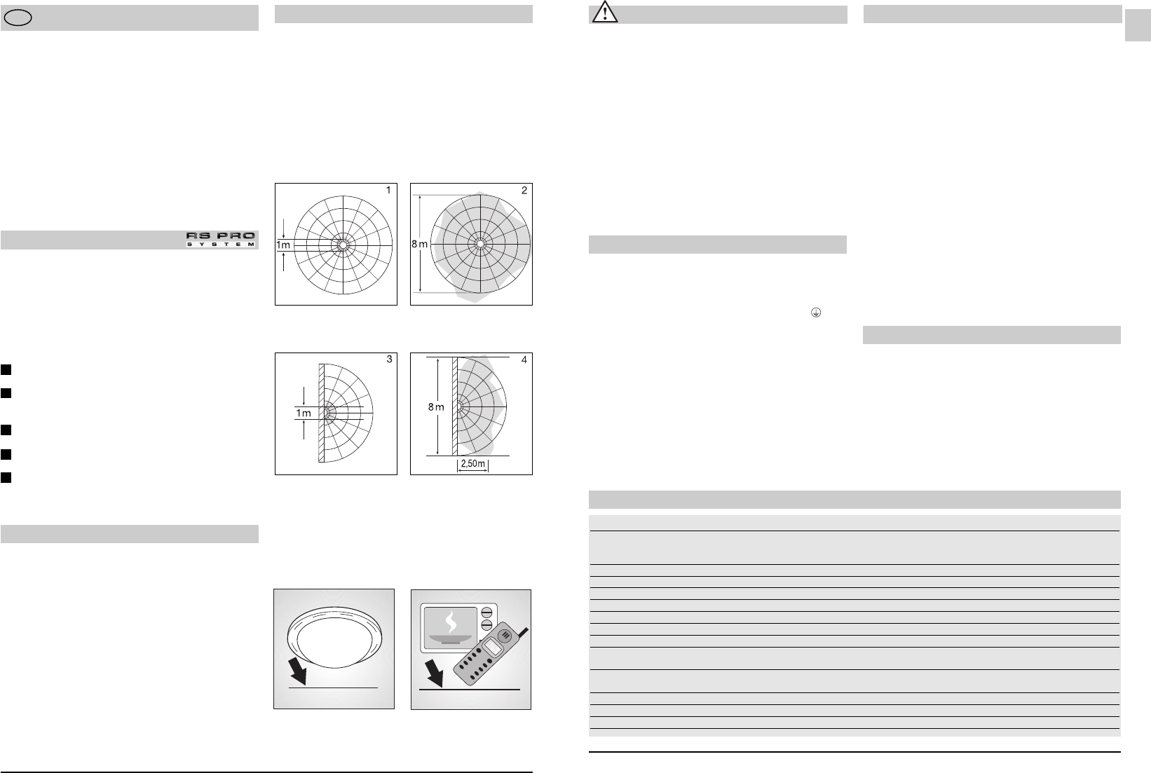
Detection zones for ceiling mounting:
1) Minimum reach (1 m dia.)
2) Maximum reach (8 m dia.)
Detection zones for wall mounting:
3) Minimum reach (1 m dia.)
4) Maximum reach (8 m dia.)
Important: Persons or objects moving towards the
light are detected best.
* only applies to RS PRO 500/1000/2000 IP65 Sensor
Note:
The high-frequency output of the HF-sensor is
approx.1 mW – that's just one 1000th of the trans-
mission power of a mobile phone or the output of a
microwave oven.
approx. 1000 mW
1
2
3
4
5
- 13 -- 12 -
approx. 1 mW
GB