Negative pressures greater than 20-25 Pa can influence correct operation. The pane can become increasingly contaminated or noise can be intensified!
Test fire performed: Yes No
The fireplace operator has been instructed regarding operation and the instructions for assembly and use have been provided:
Signatures:
Installer Stove Fitter Owner
Annual maintenance carried out:
Type of work
Name:
Date:
Signature
Caution: Keep in a safe place! Store these instructions with valid and clearly dated proof of purchase and have the documents ready for our technicians in the event of service work.
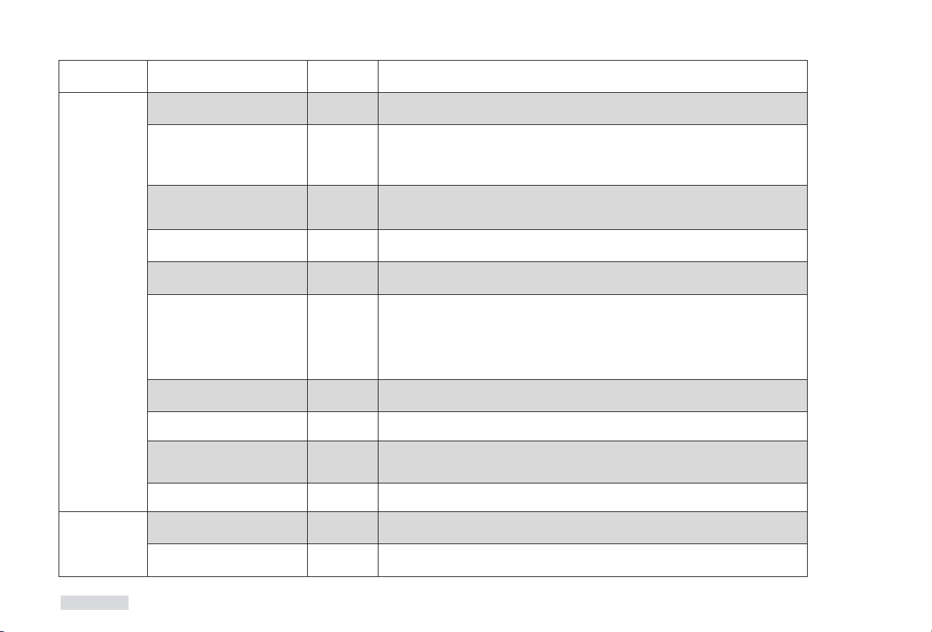
Measure temperatures directly at the inlet and outlet of the stove and
document:
Return flow temperature
in °C
Flow temperature in °C
Visual inspection of the heating system: Yes No
Function check executed: Yes No
Test fire performed: Yes No
Has the actual delivery pressure been checked? Yes No
Negative pressures greater than 20-25 Pa can influence correct operation. The pane can become increasingly contaminated or noise can be intensified!
The fireplace operator has been instructed regarding operation and the instructions for assembly and use have been provided:
Signatures:
Installer Stove Fitter Owner
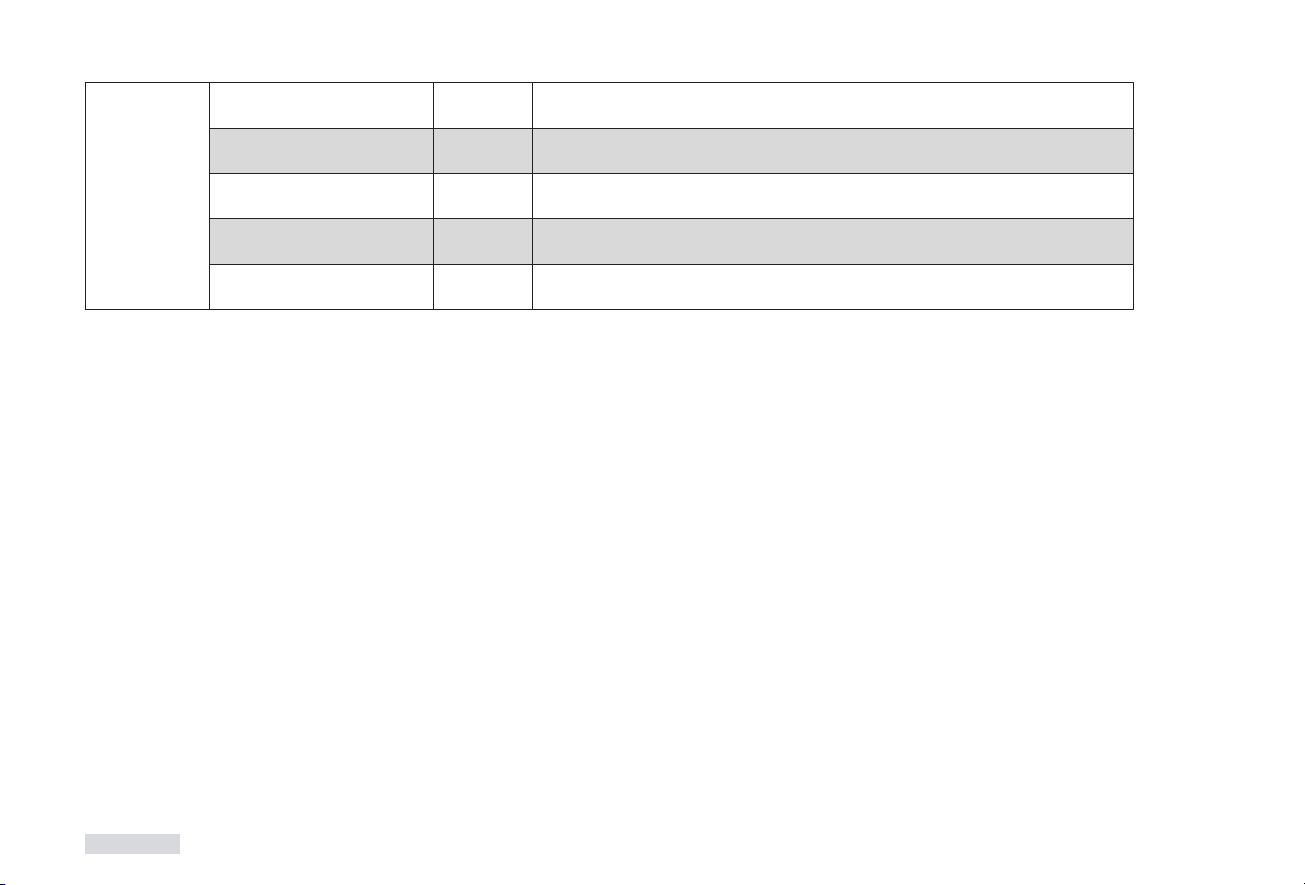
Annual maintenance carried out:
Type of task:
Name:
Date:
Signature
Caution: Keep in a safe place! Store these instructions with valid and clearly dated proof of purchase and have the documents ready for our technicians in the event of service work.
Chapter 9
55
T
H
E
F
I
R
E
C
O
M
P
A
N
Y
M
A
D
E
I
N
G
E
R
M
A
N
Y
NOTES
T
H
E
F
I
R
E
C
O
M
P
A
N
Y
M
A
D
E
I
N
G
E
R
M
A
N
Y
A1-GB-SP-1.500-03/16-DC
Your specialist dealer:
Reg. no.:Product inspected by:Date:
..
Day Month Year
SPARTHERM
The global brand for your lounge
Service hotline 0180 594 41 94
14 cents/minute incl. VAT from a German landline, max. 42 cents/minute incl. VAT.
Gebruikershandleiding.com neemt misbruik van zijn services uitermate serieus. U kunt hieronder aangeven waarom deze vraag ongepast is. Wij controleren de vraag en zonodig wordt deze verwijderd.
Product:
Spelregels forum
Om tot zinvolle vragen te komen hanteren wij de volgende spelregels:
lees eerst de handleiding door;
controleer of uw vraag al eerder door iemand anders is gesteld;
probeer uw vraag zo duidelijk mogelijk te stellen;
heeft u een probleem en al geprobeerd om dit op te lossen, vermeld dit erbij aub;
heeft u een oplossing gekregen van een bezoeker dan horen wij dat graag in dit forum;
wilt u een reactie geven op een vraag of antwoord, gebruik dan niet dit formulier maar klik op de knop 'reageer op deze vraag';
uw vraag wordt direct op de website gezet; vermijd daarom persoonlijke gegevens in te vullen;
Belangrijk! Als er een antwoord wordt gegeven op uw vraag, dan is het voor de gever van het antwoord nuttig om te weten als u er wel (of niet) mee geholpen bent! Wij vragen u dus ook te reageren op een antwoord.
Belangrijk! Antwoorden worden ook per e-mail naar abonnees gestuurd. Laat uw emailadres achter op deze site, zodat u op de hoogte blijft. U krijgt dan ook andere vragen en antwoorden te zien.
Abonneren
Abonneer u voor het ontvangen van emails voor uw Spartherm Ambiente bij:
nieuwe vragen en antwoorden
nieuwe handleidingen
U ontvangt een email met instructies om u voor één of beide opties in te schrijven.
Ontvang uw handleiding per email
Vul uw emailadres in en ontvang de handleiding van Spartherm Ambiente in de taal/talen: Engels als bijlage per email.
De handleiding is 4.14 mb groot.
U ontvangt de handleiding per email binnen enkele minuten. Als u geen email heeft ontvangen, dan heeft u waarschijnlijk een verkeerd emailadres ingevuld of is uw mailbox te vol. Daarnaast kan het zijn dat uw internetprovider een maximum heeft aan de grootte per email. Omdat hier een handleiding wordt meegestuurd, kan het voorkomen dat de email groter is dan toegestaan bij uw provider.
Uw handleiding is per email verstuurd. Controleer uw email
Als u niet binnen een kwartier uw email met handleiding ontvangen heeft, kan het zijn dat u een verkeerd emailadres heeft ingevuld of dat uw emailprovider een maximum grootte per email heeft ingesteld die kleiner is dan de grootte van de handleiding.
Er is een email naar u verstuurd om uw inschrijving definitief te maken.
Controleer uw email en volg de aanwijzingen op om uw inschrijving definitief te maken
U heeft geen emailadres opgegeven
Als u de handleiding per email wilt ontvangen, vul dan een geldig emailadres in.
Uw vraag is op deze pagina toegevoegd
Wilt u een email ontvangen bij een antwoord en/of nieuwe vragen? Vul dan hier uw emailadres in.