814899
32
Verklein
Vergroot
Pagina terug
1/97
Pagina verder
Instruction Manual
English
Water Central Heating Stoves
Models
ACQUA ECO
ACQUA ECO PV
ECOFOGO ECO
MYTHO ECO
MYTHO ECO PV
ZAIMA ECO
Please read the instructions carefully before installing, using and maintaining
of equipment. The instruction manual is an integral part of the product.
Mod. 1029 B
Thank you for purchasing a SOLZAIMA equipment.
Please read this Manual carefully and save it for future reference.
* All products comply with the requirements of the Construction Products Directive (Reg.
EU No. 305/2011), being approved with the CE conformity mark;
* Water heat recuperators for central heating are tested according to EN 13229:2001 +
EN 13229:2001/AC:2003 + EN 13229:2001/A1:2003 + EN 13229:2001/A2:2004 + EN
13229:2001/AC:2006 + EN 13229:2001/A2:2004/AC:2006 + EN
13229:2001/A2:2004/AC:2007;
* SOLZAIMA is not responsible for any damage to the equipment when it is installed by
unqualified personnel;
* SOLZAIMA is not responsible for any damage to the equipment, when the rules of
installation and use, indicated in this manual, are not respected;
* All local regulations, including so-called national and European standards, must be
respected in the installation, operation, and maintenance of the equipment;
* Whenever you need assistance, you should contact the supplier or installer of your
equipment. You must provide the serial number of your stove on the identification plate
under the ash drawer;
* Technical assistance must be carried out by your Installer or Solution Provider, except in
special cases after evaluation by the installer or technician responsible for the service, who
will contact SOLZAIMA if deemed necessary.
Contact for technical assistance:
www.solzaima.pt
apoio.cliente@solzaima.pt
Address: Rua da Cova da Areia (E.M. 605), 695;
3750-071 Aguada de Cima
Águeda Portugal
Index
1. SOLZAIMA .................................................................................................................... 1
2. TECHNICAL CHARACTERISTICS ....................................................................................... 2
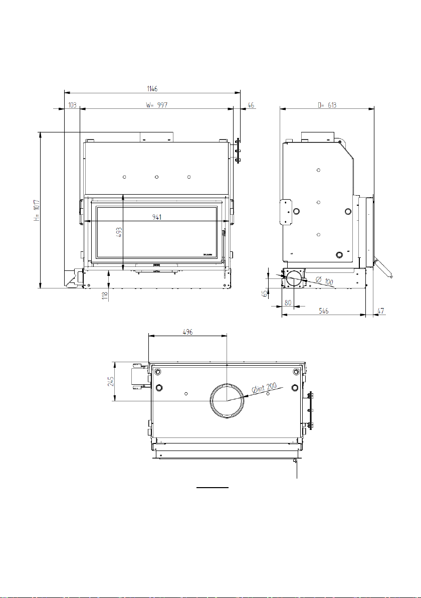
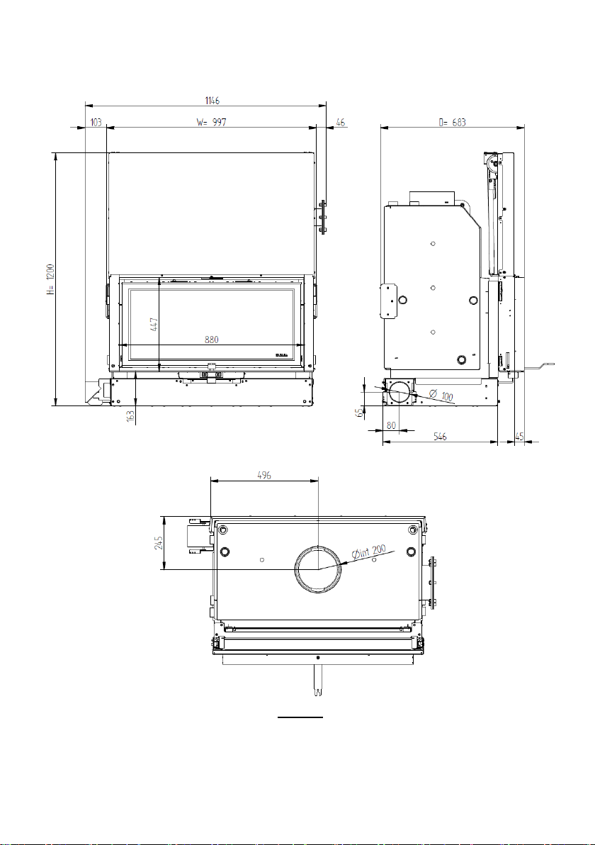
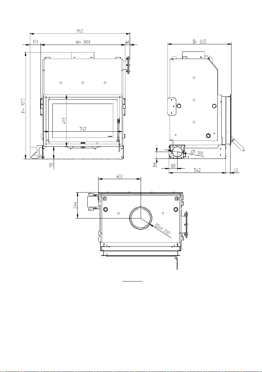
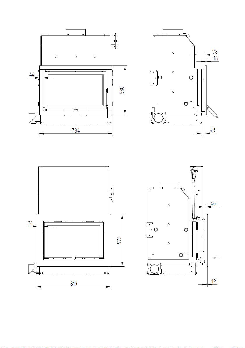
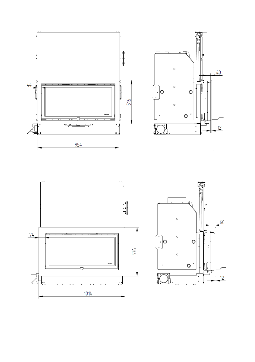
3. GENERAL MEASURES ..................................................................................................... 4
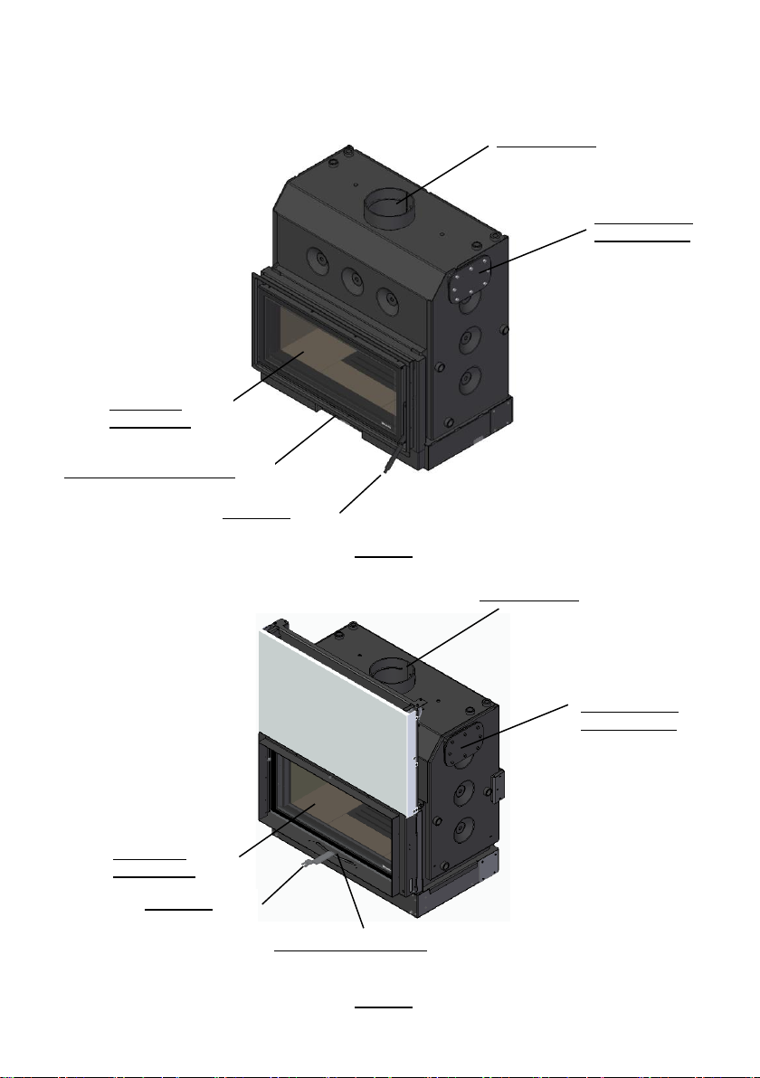
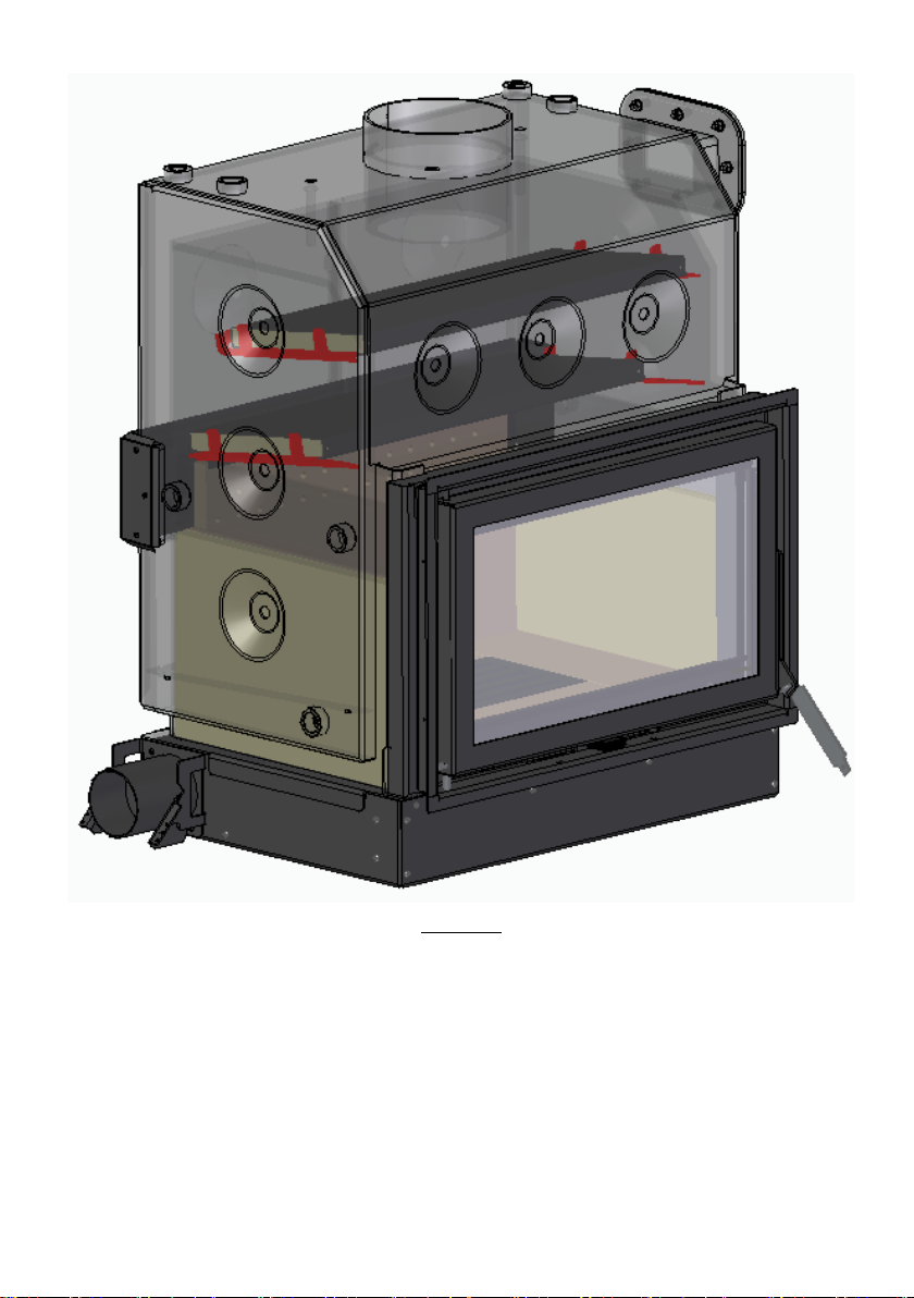
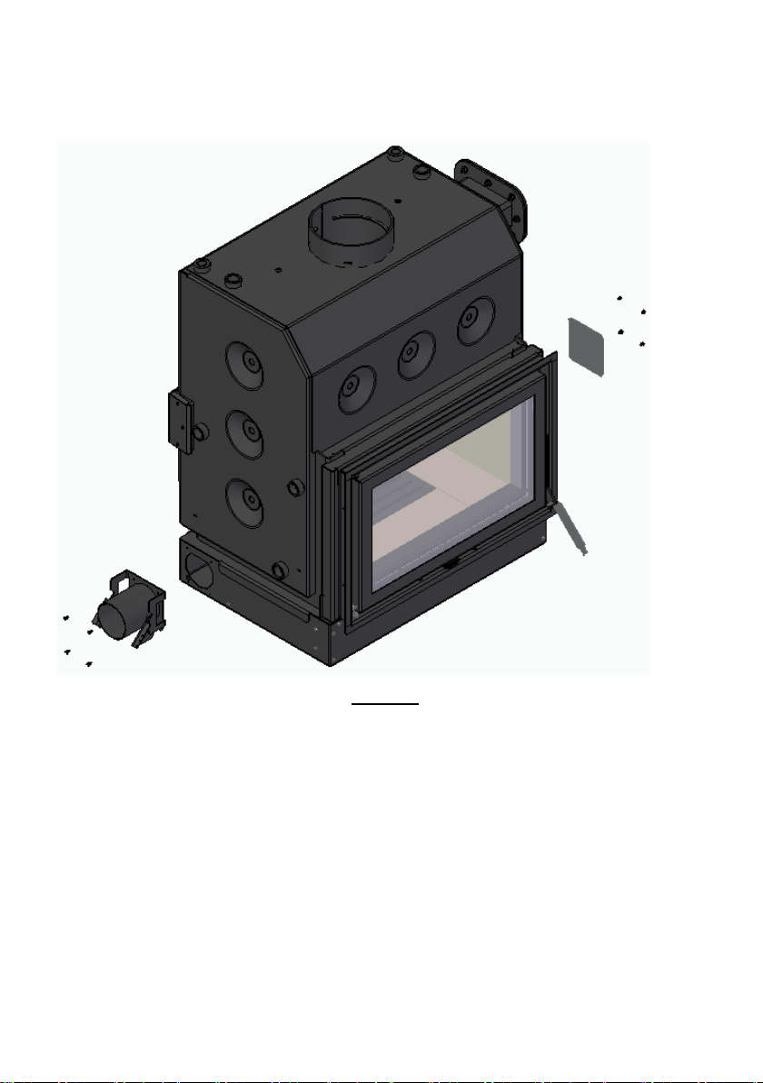
4. KNOW THE EQUIPMENT ................................................................................................ 10
5. MATERIALS OF THE RECUPERATORS ............................................................................... 13
6. INSTALLATION ............................................................................................................. 15
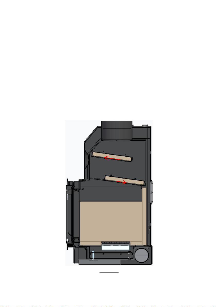
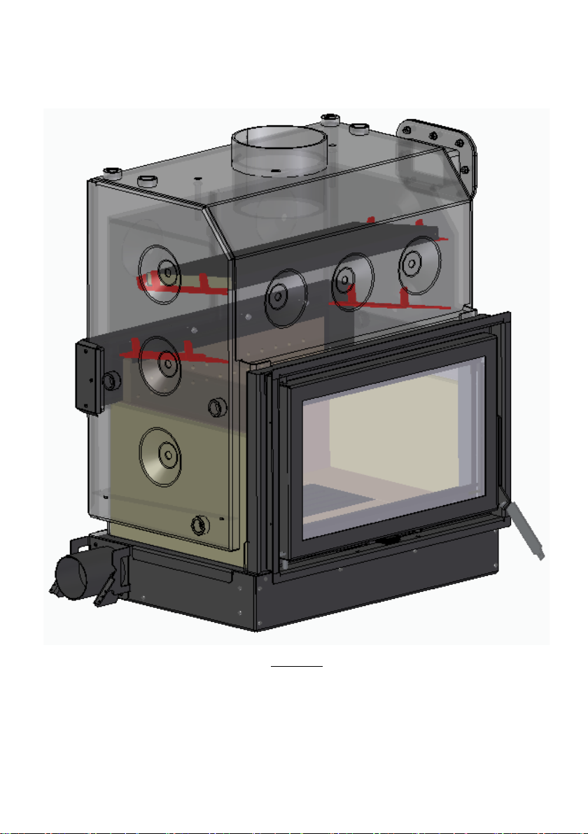
6.1. CIRCULATION OF AIR AND FLUE GASES ............................................................................... 19
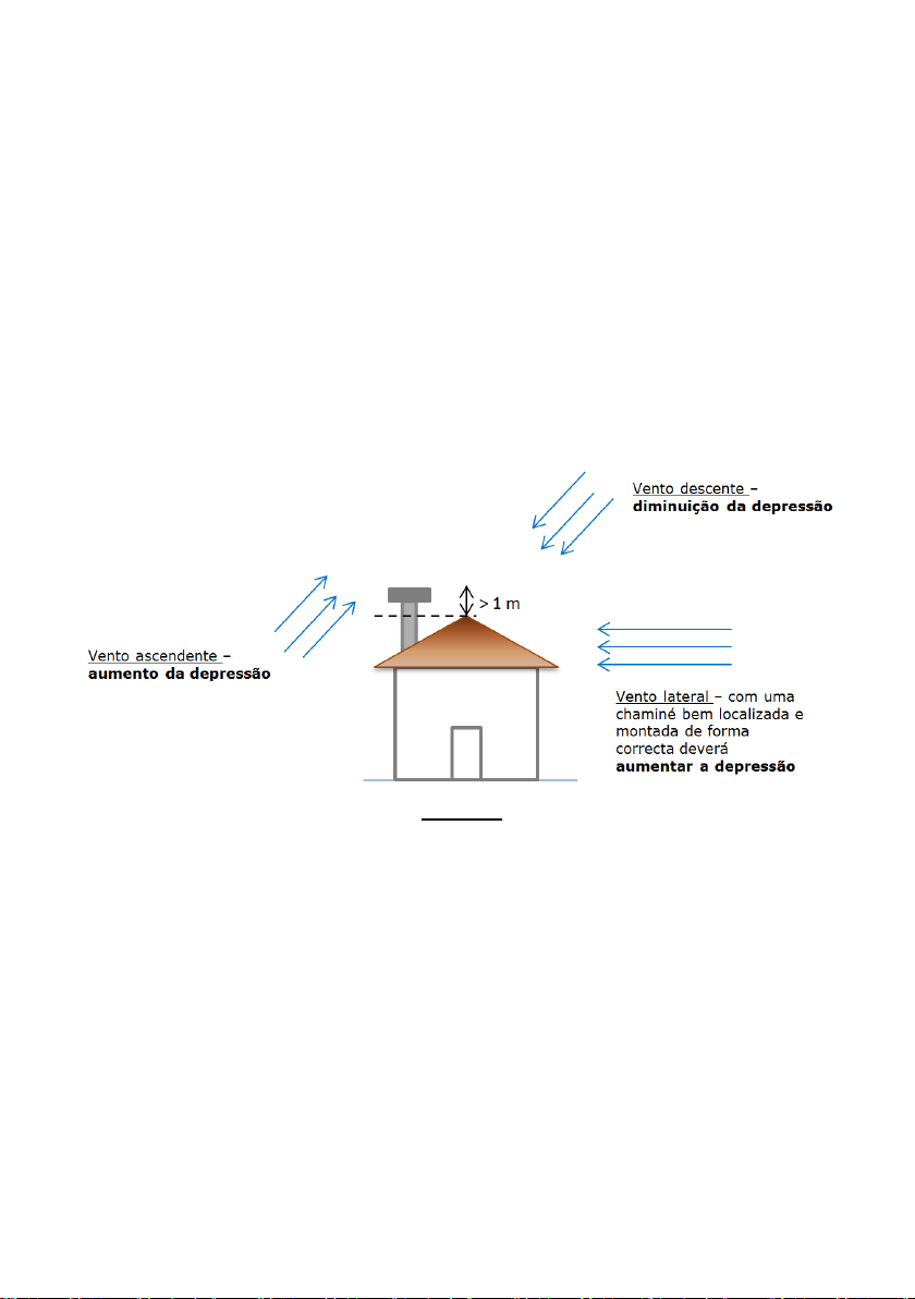
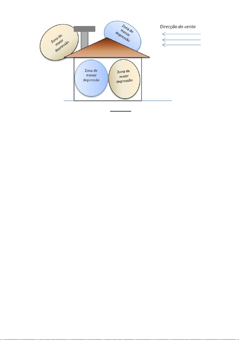
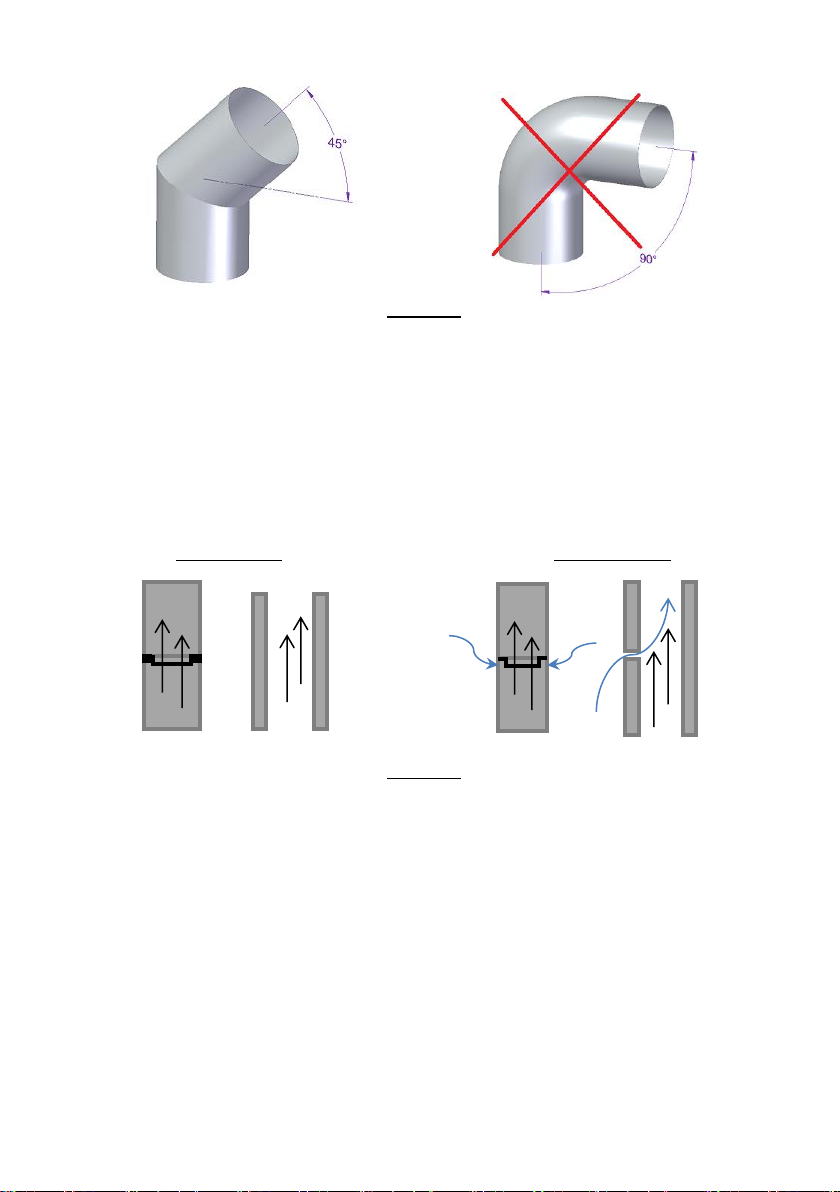
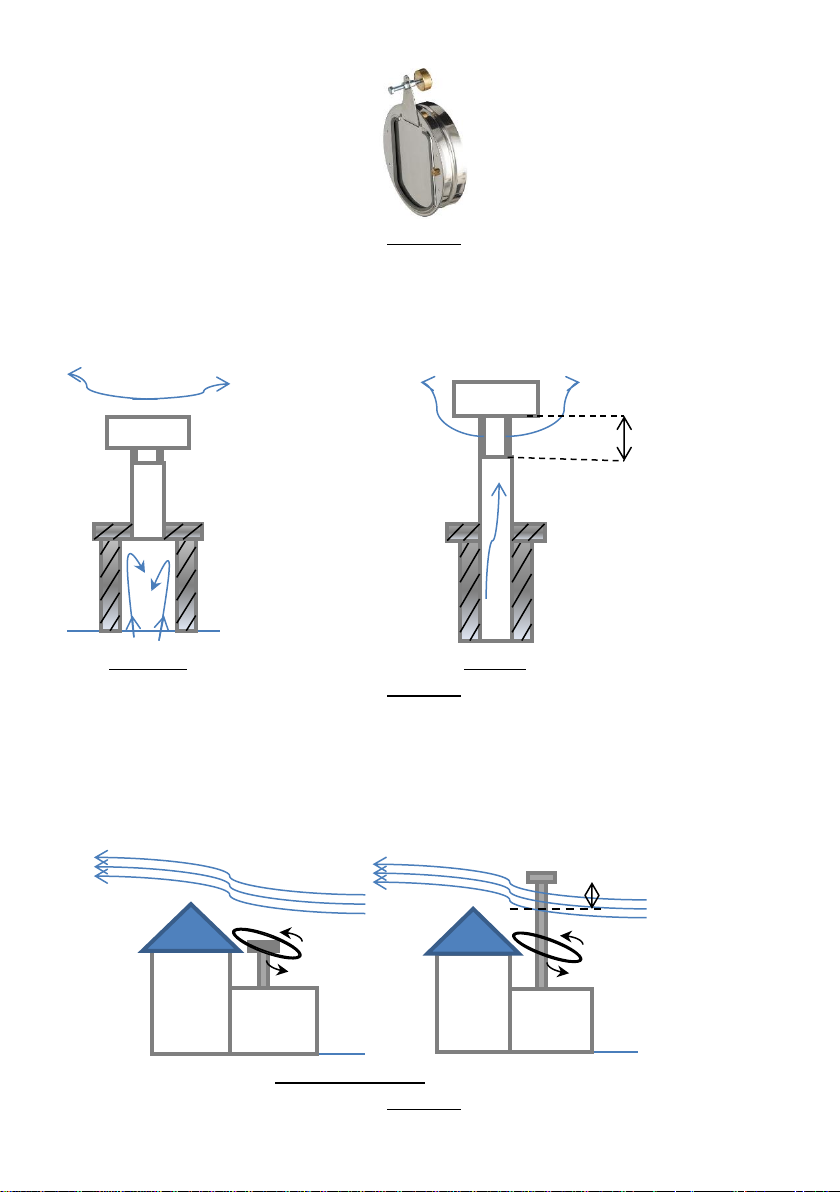
6.1.1. THEORETICAL NOTIONS FOR THE INSTALLATION OF CHIMNEYS ................................................. 19
6.1.2. INSTALLATION ADVICE .............................................................................................. 21
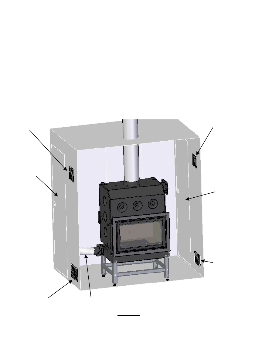
6.2. INSTALLATION LOCATION REQUIREMENTS ............................................................................ 24
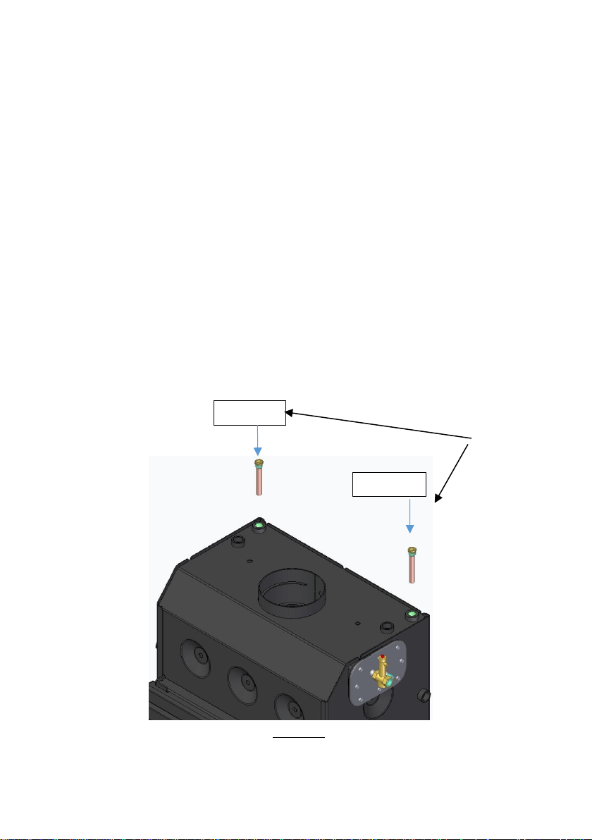
6.3. HYDRAULIC INSTALLATION ............................................................................................. 28
6.4. OPTIONAL TRIM RIM .................................................................................................... 30
6.4.1. TRIM HOOP MODELS ................................................................................................. 30
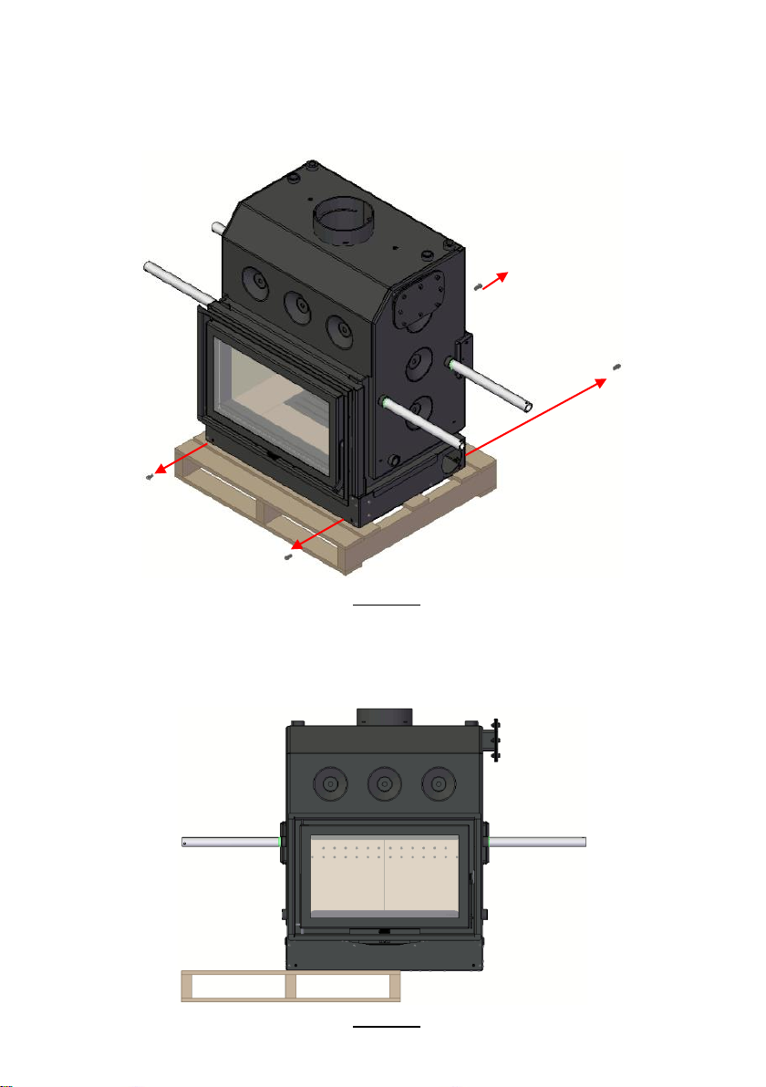
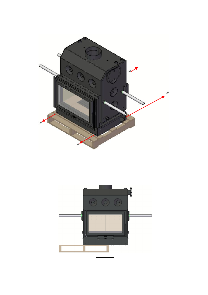
6.4.2. TRANSPORT BARS .................................................................................................... 37
6.4.3. TRANSPORT WHEELS ................................................................................................ 37
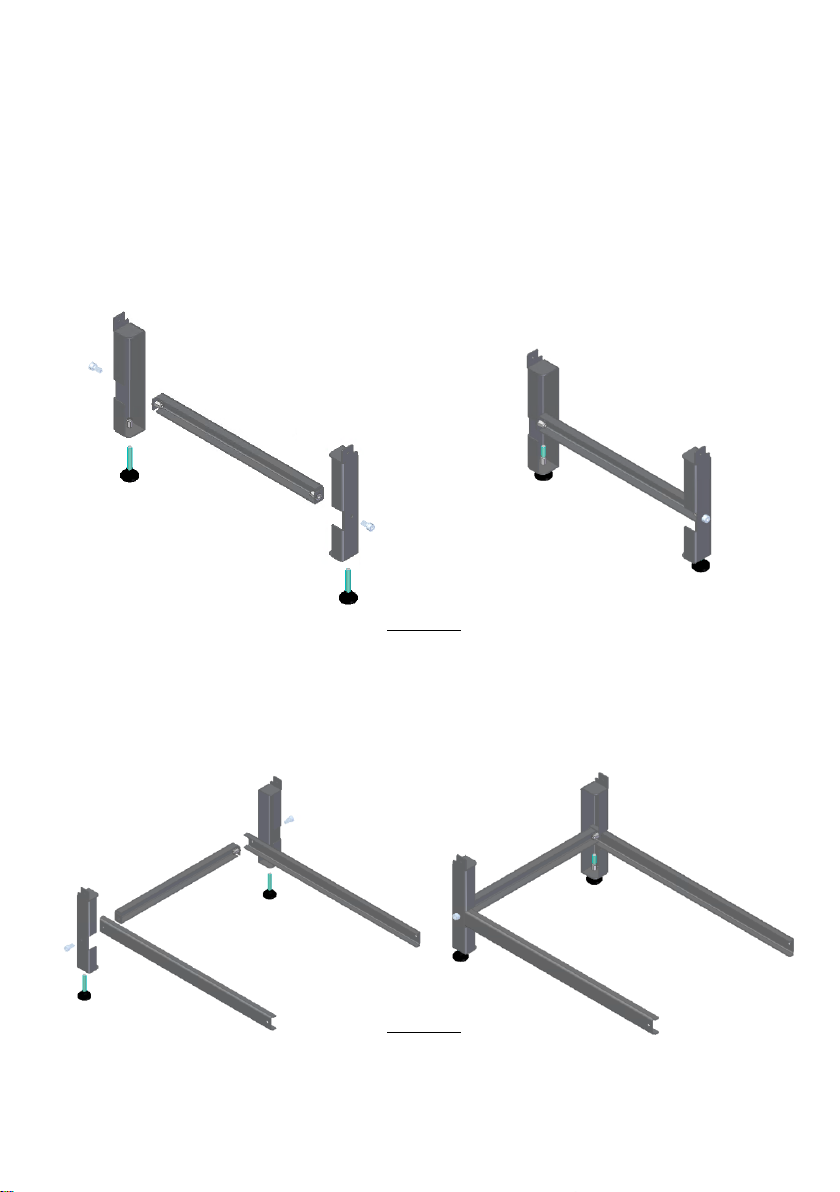
6.4.4. AUXILIARY LEVELING TABLE ........................................................................................ 40
6.4.5. ANTI-PACKAGING KIT ............................................................................................... 47
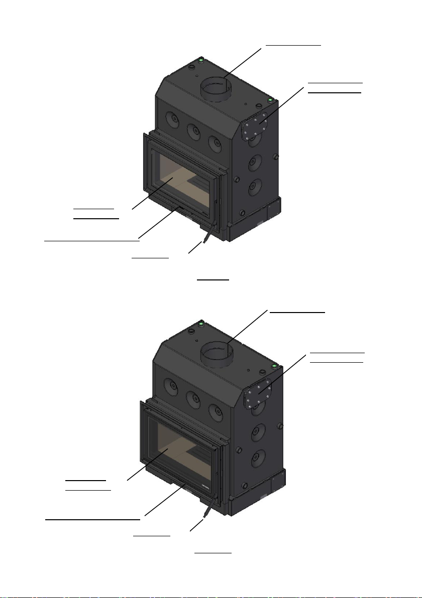
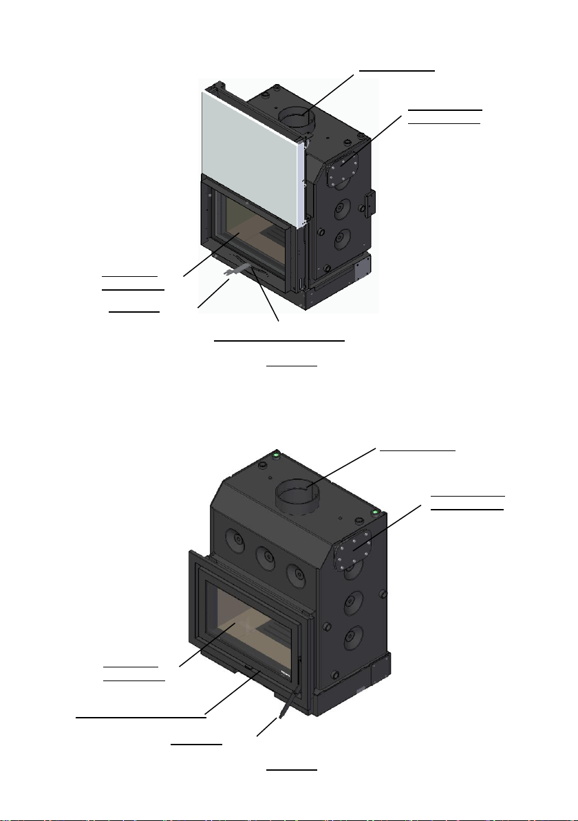
7. MAIN PARTS OF THE RECUPERATOR ............................................................................... 50
8. INSTRUCTIONS FOR USE .............................................................................................. 52
8.1. FUEL ..................................................................................................................... 52
8.1.1. POWER ................................................................................................................ 53
8.1.2. ENERGY EFFICIENCY ................................................................................................. 53
8.2. FIRST USE ............................................................................................................... 54
8.3. INSTRUCTIONS FOR USE OF THE RECUPERATOR ..................................................................... 55
8.3.1. ADJUSTMENT OF COMBUSTION CONTROL .......................................................................... 55
8.3.2. FIRING ................................................................................................................ 57
8.3.3. REFUEL ............................................................................................................... 57
8.4. SAFETY ................................................................................................................... 59
8.5. CLEANING AND MAINTENANCE ......................................................................................... 59
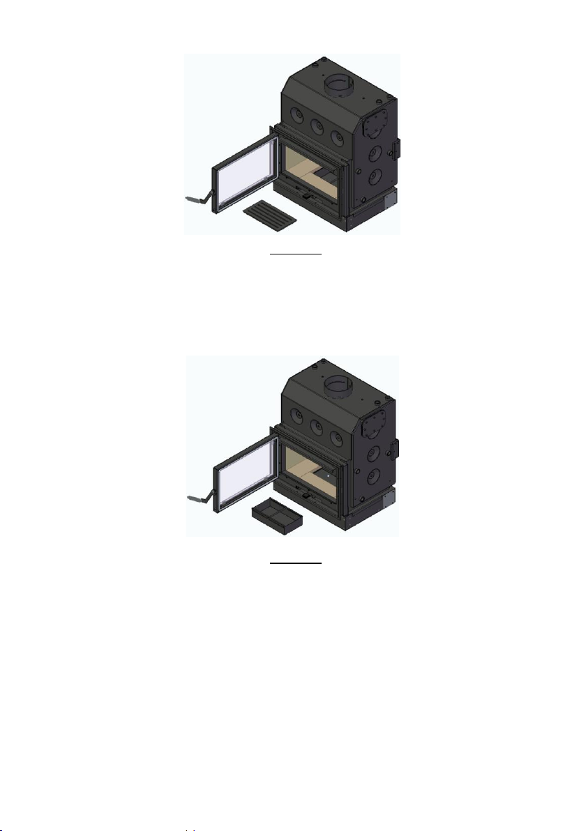
8.5.1. DAILY CLEANING ..................................................................................................... 60
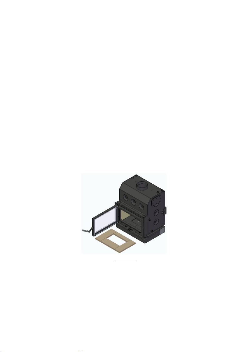
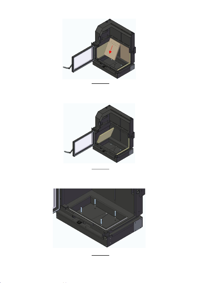
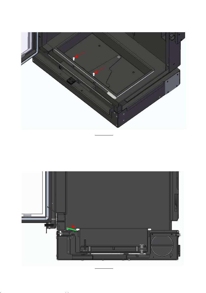
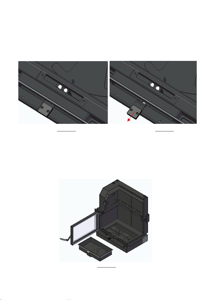
8.5.2. ADDITIONAL CLEANING ............................................................................................. 61
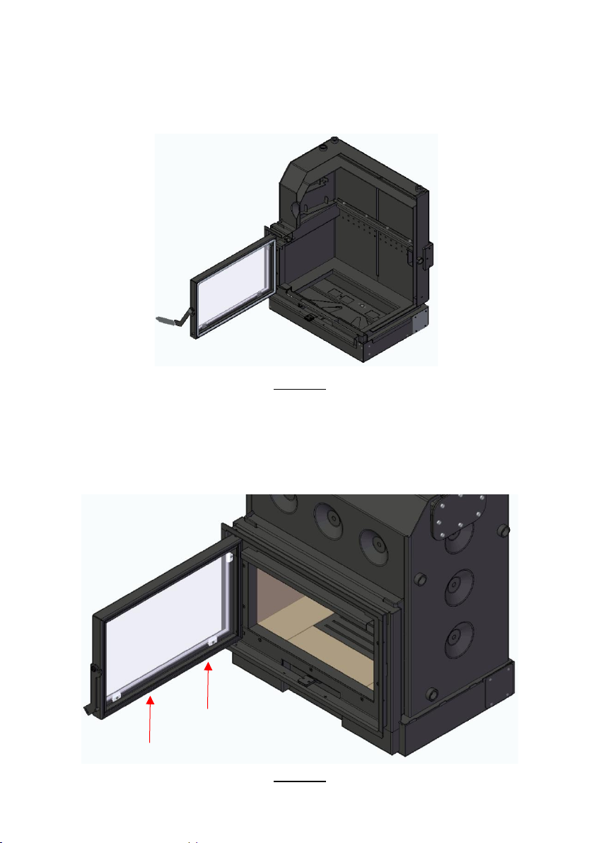
8.5.3. REMOVE THE DOOR .................................................................................................. 67
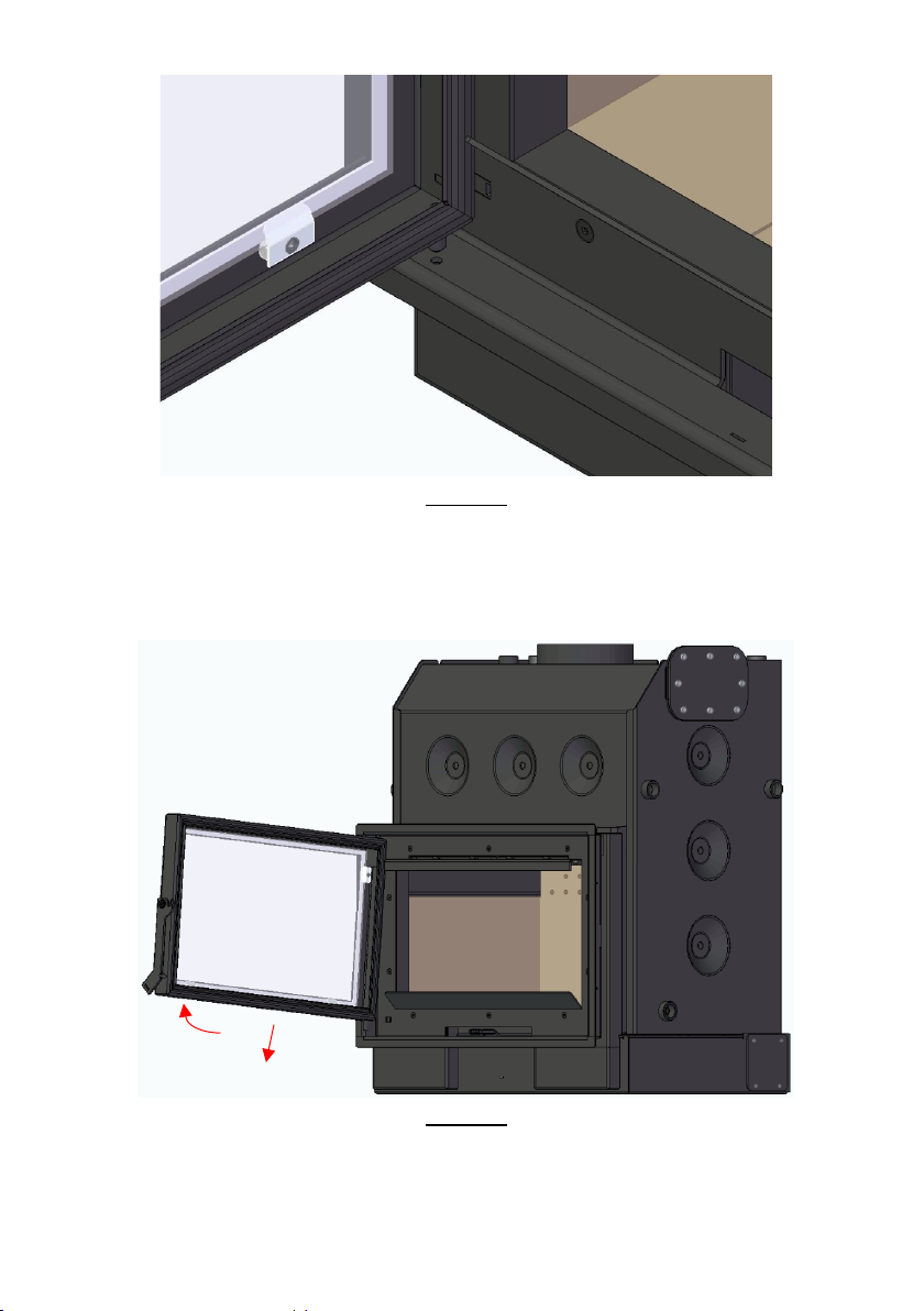
8.5.4. ADJUST THE PORT ................................................................................................... 69
9. TROUBLESHOOTING SOME ISSUES ................................................................................ 70
10. END OF LIFE OF A RECUPERATOR .................................................................................. 71
11. SUSTAINABILITY .......................................................................................................... 71
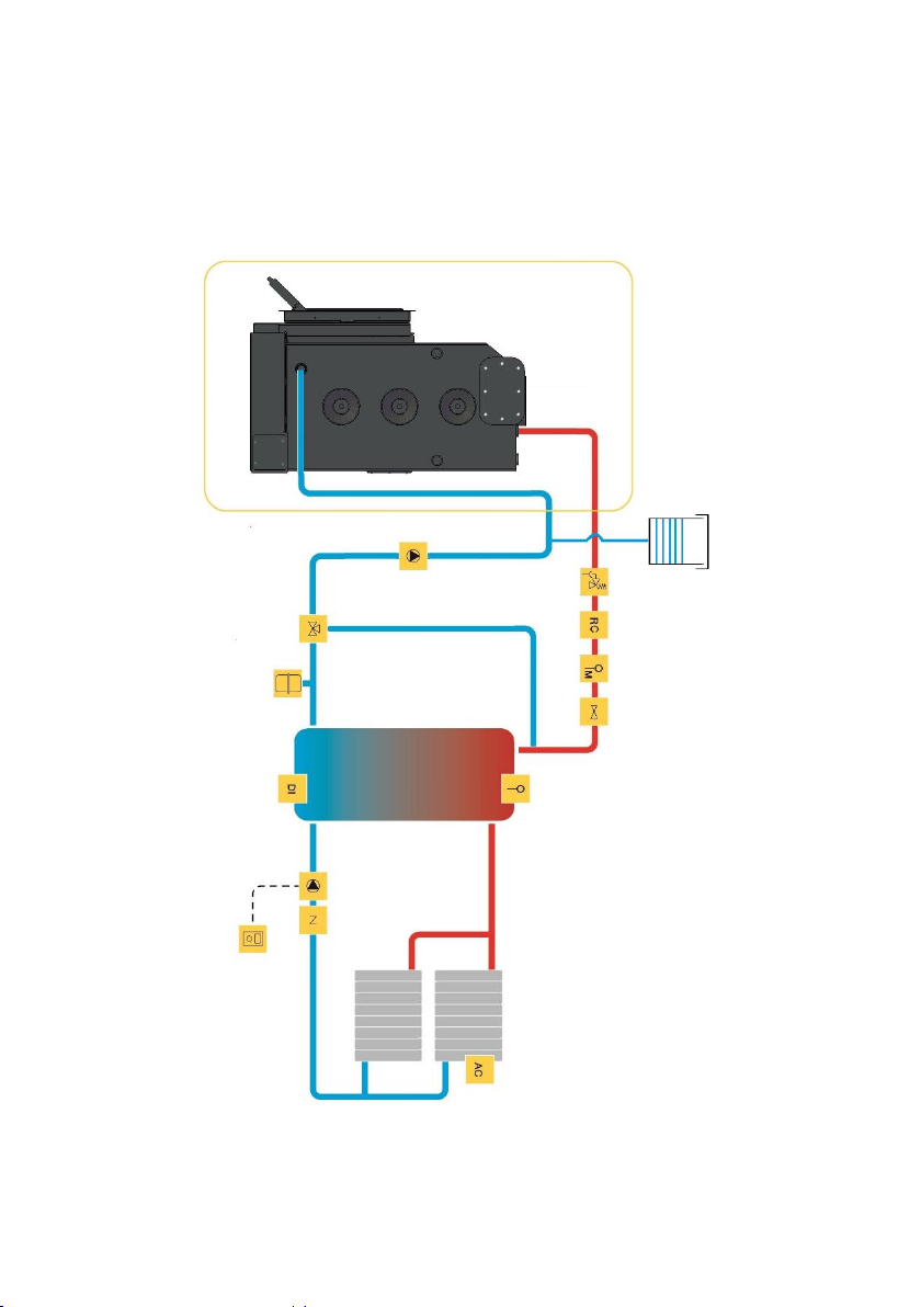
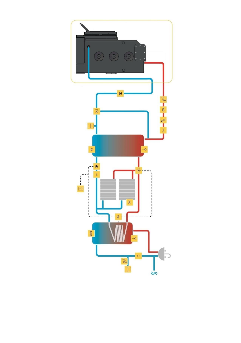
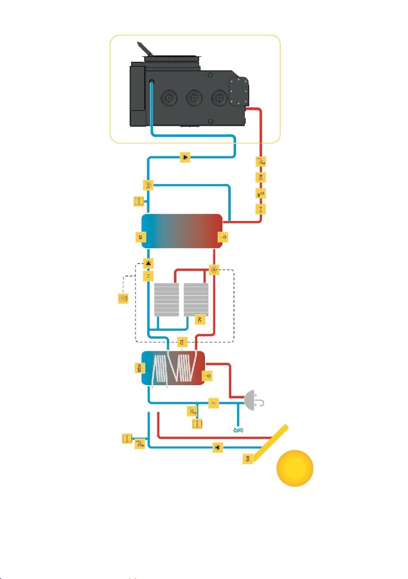
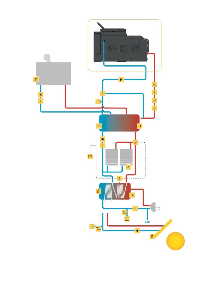
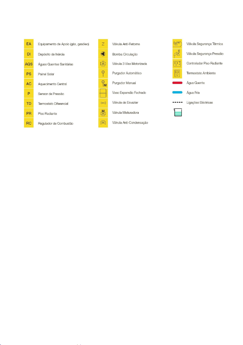
12. INSTALLATION SCHEMAS .............................................................................................. 72
13. GLOSSARY ................................................................................................................. 77
14. WARRANTY .................................................................................................................. 79
15. DECLARATION OF PERFORMANCE................................................................................... 87
1
1. Solzaima
Solzaima's innovative spirit has always been to rely on clean, renewable, and more
economical energies. For this reason, we have been engaged in the manufacture of
biomass heating systems and equipment for more than 45 years.
As a result of the persistence and unconditional support of its network of partners,
Solzaima is today a leader in the production of biomass heating, whose best example is
the water central heating recuperators and its range of pellet salamanders.
Every year we equip more than 20,000 homes with biomass heating solutions. A sign
that consumers are paying attention to the greenest and most economical solutions. Today,
wood is the most economical and sustainable way to heat your home.
Solzaima has ISO9001:2015 Quality certification and ISO14001:2015 Environmental
certification.
2
2. Technical characteristics
The Central Water Heating stoves are equipment intended for space heating and
water heating for use in central heating installations and for domestic use. For this, a pre-
installation of central heating and an accumulator with heat exchanger are necessary if
you want to heat sanitary water.
Technical characteristics transversal to this range:
* EC type-approval
* Max pressure: 3 bar
* Recommended pressure: [0.5 to 2] bar
* Maximum service temperature: 90ºC
* Average depression required: 12 Pa
* Average duration before refueling: 45 minutes
* Fuel: dry firewood
* Recommended fuel dimension: 500mm long
* Combustion chamber depth: 480mm
3
Table 1 - Technical characteristics
Features
Acqua
Echo
Acqua
Eco PV
Ecofire
Eco
Mytho
Echo
Mytho
Eco PV
Zaima
Echo
Un
Weight
245
275
225
225
265
245
Kg
Width
989
997
795
795
803
795
mm
Height
994
1200
994
994
1200
994
mm
Depth
612
683
605
605
677
600
mm
Diameter of the smoke
discharge pipe
200
200
200
200
200
200
mm
Maximum heating volume
641
641
493
493
493
493
Rated thermal input
28,2
28.2
21,7
21,7
2 1.7
21,7
kW
Air thermal power
9,5
9,5
6,3
6,3
6,3
6,3
kW
Thermal power water
18,7
18,7
15,4
15,4
15,4
15,4
kW
Fuel consumption
8,3
8,3
6,2
6,2
6,2
6,2
kg/h
Recommended firewood length
500
500
500
500
500
500
mm
Maximum firewood length
800
800
600
600
600
600
mm
Thermal efficiency at rated
thermal input
80
80
80
80
80
80
%
323
323
294
294
294
294
°C
0,068
0,068
0,066
0,066
0,066
0,066
%
11,4
11,4
11,9
11,9
11,9
11,9
%
31
31
11
11
11
11
mg/Nm³
26
26
41
41
41
41
mg/Nm³
103
103
88
88
88
88
mg/Nm³
Flue gas mass flow
21,6
21,6
15,3
15,3
15,3
15,3
g/s
Depression in the chimney
12
12
12
12
12
12
Pa
4
3. General measures
Acqua Eco
Figure 1
5
Acqua Eco PV
Figure 2
6
Ecofogo Eco
Figure 3
7
Mytho Eco
Figure 4
8
Mytho Eco PV
Figure 5
9
Zaima Eco
Figure 6
10
4. Know the equipment
Acqua Eco
Figure 7
Acqua Eco PV
Figure 8
Smoke output
Optional anti-
packaging kit
Vermiculit
plaquesand
Input regulator from ar
Door lock
Vermiculit
plaquesand
Input regulator from
ar
Door lock
Optional anti-
packaging kit
Smoke output
11
Ecofogo Eco
Figure 9
Mytho Eco
Figure 10
Smoke output
Optional anti-
packaging kit
Input regulator from ar
Door lock
Vermiculit
plaquesand
Smoke output
Optional anti-
packaging kit
Vermiculit
plaquesand
Input regulator from ar
Door lock
12
Mytho Eco PV
Figure 11
Zaima Eco
Figure 12
Smoke output
Optional anti-
packaging kit
Smoke output
Optional anti-
packaging kit
Vermiculit
plaquesand
Input regulator from ar
Door lock
Vermiculit
plaquesand
Door lock
Input regulator from ar
13
5. Materials of the recuperators
The interior of the combustion chamber of these recuperators is made of high-quality
carbon steel sheet with a thickness of 5 mm;
In the ECOFOGO ECO, MYTHO ECO and ACQUA ECO models, the door is made of 2.5
mm plate, in the ACQUA ECO PV and MYTHO ECO PV models with 3.0 mm. In the ZAIMA
ECO model, the door and rim are made of cast iron. The ash drawer on all models is
1.5mm. In the ACQUA ECO, ACQUA ECO PV, MYTHO ECO and MYTHO ECO PV models, the
door has a screen-printed glass-ceramic glass on the outside;
The models ECOFOGO ECO, MYTHO ECO, MYTHO ECO PV, ZAIMA ECO, ACQUA ECO
and ACQUA ECO PV have a heat-resistant glass-ceramic glass. This type of glass can
withstand temperatures of up to 750°C in continuous use;
The hydraulic connections are made of steel, 4 1" female bonds and 2 3/4" female
bonds;
The paint contains paint resistant to temperature peaks of up to 900°C, and to service
temperatures of about 600°C;
In the ECOFOGO ECO, MYTHO ECO, MYTHO ECO PV, ZAIMA ECO, ACQUA ECO and
ACQUA ECO PV models, the combustion chamber is coated with a heat-resistant material
(vermiculite). The lateral insulation, the back, the bottom of the deflectors are of
vermiculite, a material classified as a mineral of the hydro silicate group, resistant to
temperatures of about 1,100 °C. Due to its insulating characteristics, vermiculite allows
a better use of heat, an increase in temperature inside the chamber and cleaner
combustion (with a lower proportion of CO), as well as greater protection of the steel plate
from which the combustion chamber is made, thus prolonging the life of the recuperator;
The models ECOFOGO ECO, MYTHO ECO, MYTHO ECO PV, ZAIMA ECO, ACQUA ECO
and ACQUA ECO PV have a side cover, which allows the installation of an anti-packaging
kit (sold separately).
Installation instructions for this kit can be found in section 6.5 Installation of the anti-
packaging kit.
14
The anti-packaging kit is a mechanical safety system that prevents the equipment
from being damaged by an excess of temperature due to, for example: damaged pump,
electric current cut, etc.
The kit consists of a copper coil welded to a cap that is bolted to the body by replacing
the blind cap with 8 M8 screws. To ensure the tightness between the cap and the body, a
silicone joint is applied, which will ensure that no leaks occur. A thermal discharge valve
(not included in the kit) must be connected to the coil inlet and the outlet must be
connected to the sewer. When the water inside the body reaches a temperature higher
than 97 ± 3 °C, the valve opens the water supply network. As water circulates through
the coil, it absorbs excess heat from the water in the body, thereby reducing body
temperature. The water that has passed through the coil absorbing excess heat is directed
into the sewer.
15
6. Installation
Please note: all local regulations and standards must be complied with when installing this
equipment.
Check, immediately upon receipt, that the product is complete and in good condition.
If there is any defect or malfunction, do not install the equipment and request
the presence of the equipment supplier or a technician of the brand on site.
Check that the deflector plates are correctly placed and supported on the supports that
are welded to the sides of the body, see the following image to understand their correct
position;
Figure 13
If they are not properly applied or if it is necessary to put them back on, you should
proceed as follows:
16
- Insert the first deflector plate diagonally and place it on top of the upper brackets, place
it horizontally and lower it slowly so that the plate is centered between the side brackets
(red in the image) and leaning against the front of the body of the equipment
Figure 14
- Insert the second deflector plate in the same way as the first, up to the supports in red.
Place it in a horizontal position and slowly lower the plate so that it is centered between
the side supports (red in the image) and against the back of the combustion chamber.
17
Figure 15
- The air intake regulator can be installed on both the right and left side of the recuperator.
On the side where the air intake regulator is not installed, the cover should be placed. To
18
fix both the air intake regulator and the lid, we must use the screws that are in the bag
inside the recuperator.
Figure 16
The air intake for combustion can be done in two distinct ways:
a) Leaving the air intake regulator free and installing ventilation grilles to allow air to
enter the space where the recuperator is installed. The air intake from outside the
dwelling must always be guaranteed, it must have an area of at least 100 cm2,
without obstacles, so that the air intake is sufficient for the proper functioning of
the device.
If this is not possible, you should consider in your installation air intakes for
combustion from inside the house, considering the degree of insulation of your
home and the proximity of other appliances that consume air for its operation (for
example kitchen or bathroom exhaust fans) and that may hinder the operation of
19
your stove at the level of combustion and draft. Always confirm that the depression
one meter above the recuperator is at least 12Pa.
b) Installing an air intake duct. A 100mm diameter pipe can be connected to the air
control damper inlet and channeled to the outside of the house. The length of this
pipe should be as short as possible and it should be ensured that the airflow is not
blocked and that the air current measured at one meter above the unit is 12Pa or
higher.
6.1. Circulation of air and flue gases
6.1.1. Theoretical notions for the installation of chimneys
There are some factors that you should consider in the installation of your chimney and
that can cause significant changes in the depression created in your chimney and
consequently in the smoke draw that you will have in your equipment.
Generally, the combustion created in your recuperator greatly increases the temperature
at the beginning of your chimney, compared to the outside ambient temperature. This fact
causes inside your chimney a low pressure (next to the recuperator), which combined with
a higher pressure in the air outside the chimney generates the force that causes a natural
movement of gases through the chimney pipe, which we call natural extraction or chimney
effect, and which also causes air entry necessary for combustion inside the recuperator.
The higher the height of your chimney, the greater the difference in pressures and
therefore the greater the natural extraction or chimney effect
This effect is based on a physical calculation that leads us to indicate that the minimum
height of the chimneys, in relation to an average altitude of the terrain, the differences in
average ambient temperatures and the average operating temperatures of the
recuperators, should not be less than 4 meters. However, this measure is not binding, and
there will be chimneys working well with less height and others with higher height working
worse. The reasons for this phenomenon must be understood in order to set up efficient
chimneys. In addition to the normal geographical factors (altitude, sun exposure,
direction) and atmosphere (rain, fog, snow) that influence the drawing of a chimney and
its depression, or even the ability to extract the fumes from the recuperator, there is still
a decisive factor in many cases that must be taken into account the WIND.
In fact, the prevailing wind (which often depends on the morphology of the land and the
areas of implantation of the houses) can cause very 12 relevant changes to the depression
created in a chimney, that is, a wind with a predominantly updraft, causes an increase of
depression in the chimney and this justifies better runs. On the contrary, a predominantly
20
downwind causes a decrease in the depression in the chimney, sometimes causing positive
pressure effects, which means that it nullifies the capacity and extraction of the chimneys.
A predominantly lateral wind has an effect that will depend on the way the chimney is
mounted. To understand this effect, we can indicate that a downwind at 45 with a speed
of 8 m/s (which on a beaufort scale of winds from 0 (ploughing) to 12 (hurricane),
corresponds to a wind of 5 (cool breeze)) causes an effect of increasing the pressure by
about 17 Pa, which can nullify the effect of a chimney that has for example a normal
depression of 12 Pa.
In addition to the direction and strength of the wind and the morphology of the surrounding
terrain, the location and way of placing the chimney in front of the dwelling is also a factor
to be considered.
Figure 17
The depression differences caused by the outside wind are also felt inside the house
and the placement of stoves in the area directly exposed to the wind can increase the
depression created in the chimney, a fact that competes with the pressure caused by the
wind outside the house, which works in an inversely proportional way, that is, the zone of
lower depression will be the area directly exposed to the wind.
In most cases this is not a problem and the depression created by the height of the
chimney nullifies this effect, but whenever this case occurs, it can be compensated by
placing the chimney in the least exposed area, thus increasing the depression capacity of
the chimney.
21
Figure 18
6.1.2. Installation advice
This appliance must be installed in a place where outside air can enter freely. Any air
intake grates must be placed in a place that is not susceptible to blockage, so that there
is sufficient air at the installation site, avoiding poor draught;
The combustion air enters the recuperator through a system controlling the intensity
of the burning. No obstacles should be created to this flow;
Fans that draw air from the installation compartment shall not be used;
The use of this equipment, at the same time as other heating appliances requiring air
supply, may require the existence of additional air intakes and the installer must assess
the situation in the light of the overall air requirements;
For your recuperator to operate under normal conditions, the flue gas draw must result
in a depression of 12 Pa one meter above the chimney neck. If this is not achieved in your
chimney, your stove may not work properly, such as throwing smoke outside or consuming
too much firewood. To achieve a good installation, at least 2 meters of rigid chimney metal
pipe with the same diameter as the smoke outlet of the recuperator should be applied
vertically. Following this section, the use of piping elements with a maximum inclination
of 45° is permissible (in this case it must ensure that the chimney is properly cleaned each
year); The following figures show the correct and incorrect shape for the installation of
curves, respectively.
22
Figure 19
A single-walled pipe, installed outside or in areas subject to thermal variations, gives
rise to condensation of the water vapor present in the flue gases, so it is advisable to use
an insulated double-walled pipe.
The joints of the pipes must be very well sealed so that possible cracks do not allow
air to enter.
Correct seal Incorrect seal
Figure 20
It is recommended to install an automatic draught regulator set to 12Pa. This
mechanism will protect the recuperator from excess draught that can be produced by a
chimney with too much run, specific weather conditions or at hotter points of the
combustion cycles. Achieving stable control of the air stream will provide greater control
over the burning speed and therefore over energy input and fuel savings.
23
Figure 21
Pipe joints must not allow bottlenecks (reductions) and the inner walls must be
perfectly smooth and free from obstacles; Hats should be placed in such a way that they
do not hinder printing.
Incorrect Correct
Figure 22
The dome of the chimney shall allow good air circulation and shall be placed at least 1
m above the summit or any other obstacle less than 3 m away; If you need to increase
the circulation you should increase the height of the chimney.
Incorrect Correct
Figure 23
Minimum distance
equal to pipe
diameter
Minimum 1
m above
the highest
point
24
The same chimney should not be used for more than one appliance or open fireplace.
In the collective chimneys each one must reach the windows that must be at the same
level, independently, so that the air circulation expels the gases out.
If the chimney is brick it should not be too wide, because the smoke when spreading
cools and damages the draw. In case of difficulty in the draw, due to contrary winds, a hat
should be applied, according to what is most favorable.
6.2. Installation location requirements
The floor where the stove will be installed must allow a permanent load of 1 kg/cm².
If the load capacity of the floor is not sufficient, a rigid plate may be used for the
distribution of the load over a surface greater than that of the support of the recuperator.
Near the walls of the recuperator cannot be used combustible materials.
The dimensions of the insertion space of the recuperator must comply:
- 15 cm between the side walls of the stove and the walls of the space.
- 5 cm between the back wall of the stove and the wall of the space.
If there are significant and undesirable heat exchanges through the walls of the
insertion space, it is advisable to proceed with thermal insulation that minimizes losses.
The nominal characteristics power "water" and power "environment" are only verified in
conditions of thermal insulation of the walls of the recuperator.
The ornamental stones must have a distance from the equipment of about 5 mm, to
allow the expansion of the metallic material, as well as must be installed so that the
recuperator can be removed, without damaging it, in case of any anomaly;
The materials present in front of the recuperator must be able to withstand heating by
radiation effect through the glass of the equipment, and must not, therefore, have
combustible characteristics.
In the sealing of the chimney should be applied a refractory material - refractory
cement or other.
The use of wood in the finishes may have the inconvenience of fire risk, so we advise
its proper insulation or its non-use.
25
In these recuperators, the intake of air for combustion can be carried out in two
different ways:
a) By means of ventilation grids. Installing air intake grids for the insertion area of
the appliance, which must be done as shown in the following diagram, in order to
ensure the proper functioning of the recuperator. The air intake from outside the
dwelling must always be guaranteed and must have an area of at least 100 cm2
and without obstacles, so that the air intake is sufficient for the proper functioning
of the appliance.
If this air intake is not possible, you should consider in your installation air intakes
(minimum 100cm2) for the combustion of the interior of the house, considering
the degree of insulation of your home and the proximity of other appliances that
consume air for its operation (for example, kitchen or bathroom exhaust fans) and
that may hinder the operation of your stove at the level of combustion and current
of air.
The interior space where the stove is installed must also be ventilated so as not to
accumulate excess heat. To do this, install 2 air intakes at the bottom and outlets
at the top with minimum sections of 100cm2, as shown in the image.
26
Cabin air outlet
Figure 24
Cabin air outlet
Side
access
Passenger
compartment
air intake
Air intake
from outside
Passenger
compartment
air intake
27
Entrance duct
from the outside
Cabin air
outlet
b) Installing an air intake duct. A 100mm diameter pipe can be connected to the air
control damper inlet and channeled to the outside of the house. The length of this
pipe should be as short as possible and it should be ensured that the airflow is not
blocked and that the air current measured at one meter above the unit is 12Pa or
higher. This type of installation ensures that the combustion air always comes from
outside the house, preventing the circulation of unwanted air through the house.
This makes the installation airtight. As in the previous installation, holes (minimum
100cm2) will be required to ventilate the interior of the space where the
recuperator is installed.
Figure 25
If possible, it is advisable to install access from both sides, so that maintenance can
be carried out more easily in the future.
Passenger
compartm
ent air
intake
Passenger
compartm
ent air
intake
Side
access
Fireproof
Pladur
Cabin air
outlet
28
Option
The
Option B
6.3. Hydraulic installation
Chapter 12 "Installation Schemes" contains the possible connection schemes in the
context of a central heating installation, with or without domestic water heating.
The minimum connection temperature of the circulation pump must be 60°C in order
to avoid condensation inside the recuperator.
The pump must be applied in the return circuit of the radiators, where the temperature
is lower.
The thermostat should be dipper, and like the combustion regulator, it should be
applied to the outlet pipe for the radiators.
Fit the thermostatic valve sleeve into the free 3/4" outlet. This will depend on which
side you have installed the automatic air intake regulator. You have option A if you placed
it on the right and option B if you placed it on the left. Insert the thermostatic valve
temperature probe into the thermostatic capsule and secure it.
Figure 26
Sleeve for
valve
temperature
probe
29
If the installation option is by closed expansion vessel, this should not be less than 25
liters and the safety valves should be 3 bars (suitable for use up to 90°C). Additional
placement of a pressure and temperature safety valve (3bar / 90°C) is advised.
For the purpose of emptying the appliance, a tap must be placed in one of the outlets
provided for that purpose in the lower side of the appliance.
The heat transport fluid should be water with the addition of an anti-corrosion product,
non-toxic and in the amount recommended by the manufacturer of the product.
The automatic combustion regulator prevents the temperature of the water inside the
appliance from rising too high if the thermal input removed is lower than that produced.
It does so by reducing the primary air intake and therefore slowing down the speed of
combustion. This is an important safety and security mechanism, preventing water from
boiling and/or pressure from increasing too much, making emergency safety devices work.
The regulator must be placed in the thread indicated for this purpose in the diagram and
must be adjusted to close the primary air intake door at 80°C in order to achieve the
proper functioning of any of the equipment referred to in this manual, the
automatic combustion regulator must always be installed.
If there is a risk of freezing in the space where the recuperator is located or in the fluid
ducts, the installer shall add to the circulating fluid an antifreeze in the proportion
recommended by the respective manufacturer to avoid freezing at the expected absolute
minimum temperature.
Never turn on the recuperator without the hydraulic circuit being full of fluid and in full
operation.
It is essential to be able to access the various components of your hydraulic installation
during the life of your equipment, in order to be able to carry out its regular maintenance
and intervene or replace the components that are necessary over time.
30
6.4. Optional trim rim
6.4.1. Trim hoop models
The finishing rim is an optional piece, which you can purchase to improve the aesthetics
of the Ecofogo Eco, Mytho Eco, Mytho Eco PV, Acqua Eco and Acqua Eco PV recuperators.
In the Zaima Eco model the rim is in casting and will be included in the equipment. You
can choose between wide, narrow and narrow glass rims.
Rims for Ecofogo Eco, Mytho Eco:
Rim 7,4cm P=4cm Black ref: MO1160P029
Rim 7,4cm P=4cm Grey ref: MO1160P025
Rim 4,4cm P=4cm Black ref: MO1160P028
Rim 4,4cm P=4cm Grey ref: MO1160P024
31
Rim 4,4cm P=4cm glass ref: MO1160P030
Rims for Mytho Eco PV:
Rim 7,4cm P=4cm ref: MO1160P076
32
Rim 4.4cm P=4cm ref: MO1160P082
Rim 7,4cm P=6cm ref: MO1160P090
33
Rim 4,4cm P=6cm ref: MO1160P089
Rims for Acqua Eco:
Rim 7,4cm P=4cm ref: MO01160G020
34
Rim 4,4cm P=4cm ref: MO01160G019
Rims for Acqua Eco PV:
Rim 7,4cm P=4cm ref: MO01160P084
35
Rim 4.4cm P=4cm ref: MO1160P083
Rim 7,4cm P=6cm ref: MO1160P088
36
Rim 4,4cm P=6cm ref: MO01160P087
If you want to install the finishing hoops in the Ecofogo Eco, Mytho Eco, Mytho Eco PV,
Acqua Eco and Acqua Eco PV recuperators , you must proceed as follows:
a) Open the door.
b) Place the 4 M4 screws supplied with the rim, but do not tighten them completely.
c) Place the rim in the recuperator, until fully against the front wall.
d) Tighten the screws until the rim is fixed in the desired position.
Figure 27
37
6.4.2. Transport bars
The equipment is very heavy and bulky. In order to be able to move it more easily,
we recommend that you buy the transport bar kit. This kit is an optional accessory that
can be purchased separately. It consists of 4 steel rods painted black with a threaded end
to attach very firmly to the body of the equipment. It can be purchased as an accessory
with the following reference:
CA01080001 It is common to all models
Figure 28
6.4.3. Transport wheels
In order to move the equipment more easily, we recommend that you purchase the
transport wheel kit. This kit is an optional accessory that can be purchased separately. It
consists of 4 wheels with adapter plates that can be fixed directly to the base of the
equipment. The 4 wheels can rotate on themselves, which will make it easier to maneuver
the equipment until it is placed in its final location. It can be purchased as an accessory
with the following reference:
CA01080002 It is common to all models
To install the wheels on the equipment, we recommend that you get the transport
bar kit mentioned in the previous point to make the job easier.
Follow the assembly order presented below to make the operation as simple and safe
as possible.
Remove all the packaging that surrounds the equipment and leave it on the pallet,
remove the parts that are inside the combustion chamber, in this way you will avoid some
38
weight and bumps or damage. Remove the 4 screws DIN 6921 M6x20mm with the help of
a 10mm wrench. If you have the carry bars, screw them until they are firm. You must
have the equipment as shown in the following image.
Figure 29
Move the equipment on the pallet so that one side of the equipment is in the air, do
not go beyond the middle of the equipment so that it is stable on the pallet when it is at
rest.
Figure 30
39
Put a wheel on the two corners that are in the air, note that there are 2 different
types. Secure them to the base with the 2 screws you removed earlier.
Figure 31
Move the equipment over the pallet, leaving the left front corner in the air, as shown
in the image. Place the wheel and fix it with the screw, as was done with the previous
wheels.
Figure 32
40
Move the equipment on the pallet leaving the left rear corner in the air, as shown in
the image. Place the wheel and fix it with the screw, as was done with the previous wheels.
Figure 33
Lift the equipment from one side and completely remove the pallet. Now you can
move the equipment easily and take it to your final location. To disassemble the wheels,
you can make the same order, but in the reverse order to the one used to assemble them,
if you do not have space to use the pallet at its destination you can use something that is
strong, stable and of similar height. Remember to protect the floor if the place where you
will perform the tasks is fragile.
6.4.4. Auxiliary leveling table
41
The side table is recommended for any model, but especially in the case of the Mytho
Eco PV and Acqua Eco PV, due to the door opening and closing system. The table assembly
process is practically the same for all models, the only thing that changes is the size, but
it is the same philosophy. It can be purchased as an accessory with the following reference:
PA1090G070 - For Ecofogo, Mytho Eco, Mytho Eco PV and Zaima Eco models
PA1090G071 For Acqua Eco and Acqua Eco PV models
In the box you will find the following components:
4 vertical columns 2 front and rear side rails
2 left and right side rails 4 screws DIN 912 M10x20mm
4 ft M10 levelers.
To assemble the leveling table, we recommend that you buy the transport bars shown
above (optional accessory), which make it easier for you to handle the equipment.
Follow the assembly order to make assembly easier and safer.
If possible, transport the unit with the packaging to the installation site using a pallet
truck. If this is not possible, we recommend that you purchase the transport wheel kit
(optional accessory), which will be discussed in the following points.
42
The equipment is very heavy, if it has no machinery, it needs to be handled by more
than one person.
The first step is to assemble a series of parts so that they are ready before you start
moving the equipment. Place the 4 feet levelers on the 4 vertical columns, screwing them
to the bottom. With the help of an Allen wrench No. 6, mount 1 vertical column with its
symmetrical by means of 1 side rail (the shortest) using 2 screws DIN 912 M10x20mm.
You will get a subset like the one in the following figure, it is not necessary to tighten the
screws well, since you will have to remove them later.
Figure 34
To tighten the 2 screws DIN 912 M10x20mm you will have to use the Allen key nº6
the process is very similar to the previous step, but in this case you will have to place the
front and rear rails (the longest ones) between the vertical columns and the side beam.
Tighten the screws but do not tighten them to allow the subassembly to fit the equipment.
Figure 35
Remove all the packaging that surrounds the equipment and leave it alone on the
pallet, remove the parts that are inside the combustion chamber, in this way will avoid
some weight and bumps or damage. Remove the 4 screws DIN 6921 M6x20mm with the
43
help of a 10mm wrench. If you have the carry bars, screw them until they are firm. You
must have the equipment as shown in the following image.
Figure 36
Move the equipment on the pallet so that one side of the equipment is in the air, do
not go beyond the middle of the equipment so that it is stable on the pallet when it is at
rest.
Figure 37
44
Tilt the equipment using the transport bars, to gain the necessary space and place
the first subset that we have assembled. Fix the subassembly by placing two of the screws
we removed earlier (DIN 6921 M6x20mm) and secure them tightly.
Figure 38
With the help of the transport bars, lift the equipment so that the pallet can be
removed. Do this carefully, as the structure of the table is not yet very stable, since it is
not yet complete.
Figure 39
45
Place the second subassembly in the position you can see in the following image, use
the other 2 screws removed earlier (DIN 6921 M6x20mm) to attach the subassembly to
the equipment. Pay special attention to the position of the front and rear rails, as you can
see in the image below, they should be inside the vertical columns of the subassembly. If
you do not, you won't be able to put them in their place afterwards.
Figure 40
Remove the screws and the side member from the first sub-assembly, put the front
and rear limbs in place and replace, this time within the front and rear limbs, the lateral
limb. Fix it again with the screws. Before tightening all the screws well, carefully check the
position of all the parts for maximum perpendicular to each other.
Figure 41
46
With the machine in its final position, perform the leveling using the 4 feet of leveling
and a level that we recommend to place on the door rim to level the left right position and
inside the combustion chamber to level the front and back. Remember to check again
when you have finished both positions, as changing one level may affect the other.
Remove the transport bars and continue with the installation of the equipment.
Figure 42
47
6.4.5. Anti-packaging kit
On the right side of the recuperator there is the possibility of installing an anti-
packaging kit. This kit is an optional accessory that you can purchase separately.
You can buy as an accessory with the following reference:
PA1026P019 It is common to all models
In the kit you will find the following, a copper coil connected to threaded sockets to
connect the heat sink.
Figure 43
For the installation of the anti-packaging kit, you must proceed as illustrated in the
following steps:
Remove the screws and nuts in order to remove the side cover.
Figure 44
48
Place the kit in the same position as the cap, making sure that the silicone gasket
is centered in relation to the holes. Place the screws without tightening them completely
and after verifying that everything is correctly positioned, tighten them alternately to
ensure correct tightness.
Figure 45
Finally, you must install the 97ºC thermostatic valve (not provided in the kit) in
the top connection of the anti-packaging kit. This valve must be connected to the water
network of the public network, with a minimum pressure of 3 bar and the water
temperature must be 10 ± 5ºC. The other connection of the kit must be connected directly
to the sewer.
Figure 46
Mains water
intake
Water outlet for
sewage
49
Note: Do not connect the anti-packaging kit to a water supply that relies on
electricity for service, e.g., well water.
The circuit that supplies the anti-packaging kit must be independent of the
heating circuit to which the recuperator is connected.
Before connecting the thermal discharge valve, check the direction of circulation
of the water, as a rule, indicated with an arrow on the valve body.
Figure 47
At the end of the installation of the anti-packaging kit and before starting
the operation of the equipment, you should test the installation verifying
that there are no leaks.
50
Combustion
control
7. Main parts of the recuperator
Figure 48
Bearings for
fixing
transport
tools
Smoke outlet
Ø200mm
Cajón de
cenizas
Door closing and
combustion
control
F-1 fluid return
or emptying"
Fluid sa ida
or probe dthe
thermostat F-
1"
Automatic air
intake regulator
or sheath Is F-
3/4" safety
valve
temperature
probe
Air inlet
Ø100mm
51
Cover for installation
anti packaging kit
Figure 49
Ash grill and
drawer
Vermiculit
plaquesand
Air inlet cover
Bearings
for fixing
transport
tools
Return or emptying /
filling of F-1" fluid
52
8. Instructions for use
Please note: all regulations and standards must be complied with when installing this
equipment.
8.1. Fuel
In this type of equipment should be used only dry firewood. It cannot be used as an
incinerator and other materials such as coal, wood with paints, varnishes, thinners, liquid
fuels, glues, and plastics must be excluded. Also avoid burning common combustible
materials such as cardboard and straw. Firewood must have a low moisture content (less
than 20%) to achieve efficient combustion, avoid creosote deposit in the smoke pipe and
glass and minimize the oxidation of the equipment.
Table 2 - List of the Type of Firewood that can be used in a SOLZAIMA Heat
Recovery Unit, its Geographical Distribution and Calorific Value/Reactions
Common
Name
Scientific
Name
Distribution
(total: 18 districts)
Features
Smoke
Heat
Firing
Combusti
on Speed
Hardne
ss
Pine
Pinus
Bragança, Castelo
Branco, Coimbra,
Guarda, Leiria, Viana
do Castelo, Vila Real
and Viseu
Little
Strong
Easy
Fast
Soft
Cork oak (+)
Quercus
suber
Évora, Faro,
Portalegre, Santarém
and Setúbal
Little
Very
strong
Easy
Medium
Hard
Eucalyptus
Eucalyptus
Aveiro, Porto and
Lisbon
Very
much
Mediu
m
Difficult
Slow
Hard
Holm Oak (+)
Quercus
ilex
Beja and Évora
Little
Very
strong
Difficult
Slow
Hard
Olive tree
Olea
All country except
Alpine areas
Little
Very
strong
Difficult
Slow
Hard
Oak
Quercus
The whole country
with subspecies
variation
Little
Strong
Difficult
Slow
Hard
Ash
Fraxinus
Riverside areas
(Baixo Vouga)
Mediu
m
Strong
Difficult
Slow
Hard
Birch / Birch
Birch
Highlands (Serra da
Estrela)
Little
Very
strong
Easy
Fast
Soft
Beech
Fagus
Regions with cold
climate and high
humidity (North of
Portugal Serra do
Gerês)
Little
Strong
Difficult
Slow
Hard
Elm
Ulmos
All country except
Alpine areas
(wetlands)
Mediu
m
Strong
Difficult
Slow
Hard
Maple / False
Maple
Acer
Minho, Beira Litoral
and Serra de Sintra
Little
Mediu
m
Medium
Slow
Soft
53
Poplar
Populus
The whole country
with predominance in
the Center
Little
Strong
Easy
Fast
Soft
Chestnut tree
Castanea
North and Central
Portugal and
mountains
Mediu
m
Strong
Difficult
Slow
Hard
8.1.1. Power
The power of your stove indicates the heating capacity, that is, the heat transfer that
your equipment will make of the energy of the firewood to your home, usually measured
in kW, and directly depends on the amount of firewood that you put in the equipment.
Rated power is the power produced by the combustion of a controlled load of wood at
a given time. This value is obtained in tests carried out in a laboratory accredited according
to the standard.
The power of use is a recommendation of the manufacturer testing the equipment with
loads of firewood within the reasonable parameters of minimum and maximum operation
of the equipment. This minimum and maximum power of use will have different firewood
consumption per hour.
8.1.2. Energy efficiency
When it comes to the energy required to air condition a home, two main parts must be
defined. The insulation of the house, which will affect the heat loss of the house, making
it necessary the entry of heat to maintain the same temperature, and the performance of
the stove that generates the heat, which will require more or less wood to produce the
same amount of heat. The combination of these two parts primarily defines energy
efficiency. Greater energy efficiency allows for a significant reduction in energy needs,
thereby reducing global dependence on fossil fuels and other non-renewable energy
resources.
In this way, energy efficiency alone can lead to significant economic and environmental
savings.
The Ecofogo ECO, Mytho Eco, Mytho Eco PV, Acqua Eco, Acqua Eco PV and Zaima Eco
recuperators have an efficiency of 80%, being well above what the standard requires and
making the energy efficiency of your home significantly better.
3
54
An efficiency of 80% means that the stove can use 80% of the energy contained in
the wood to heat the house.
As an example, see the following comparison of wood consumption in 1 hour to heat a
room of approximately 35m² with a 5kW appliance.
Figure 50
8.2. First use
Request the installer to start the equipment after verifying the operability of the
installation;
In the first use of the heat recuperator the paint is cured, which can give rise to the
production of additional fumes. If this is the case, you should air the compartment, opening
the windows and doors to the outside.
EFFICIENCY CLASS*
EFFICIENCY LIMITS*
(reclaimer door
closed)
70 %
60% < 70 %
50% < 60 %
30% < 50 %
In a conventional fireplace with
a yield of 10%, it is necessary
to consume 12 kg of firewood
In a fireplace with fireplace
(class 4) with a yield of 30%, it
is necessary to consume 4 kg of
firewood
In a recuperator with a yield of
50% (class 3), it is necessary to
consume 2.4 kg of firewood
In a Solzaima recuperator with
a yield of 75% (class 1), it is
necessary to consume only 1.6
kg of firewood
55
8.3. Instructions for use of the recuperator
8.3.1. Adjustment of combustion control
In the central part under the door, you will find the hole to fit the tool in order to move
the combustion control safely. In the Ecofogo Eco, Mytho Eco, Zaima Eco and Acqua Eco
models, the tool is inserted horizontally into the hole, as can be seen in the following
images.
Figure 51
In the Mytho Eco PV and Acqua PV models the tool inserts itself into the hole vertically,
as shown in the following images.
Figure 52
In the leftmost position, both the primary and secondary air inlet are closed, only a
small secondary air flow is allowed for safety reasons, to avoid possible gas concentrations.
This position is used when the recuperator is turned off.
Figure 53
When the control is moved to the central zone, the secondary air is opened until it
reaches 100% at the central point. The primary air remains closed.
EFFICIENCY CLASS*
EFFICIENCY LIMITS*
(reclaimer door
closed)
70 %
60% < 70 %
50% < 60 %
30% < 50 %
EFFICIENCY CLASS*
EFFICIENCY LIMITS*
(reclaimer door
closed)
70 %
60% < 70 %
50% < 60 %
30% < 50 %
EFFICIENCY CLASS*
EFFICIENCY LIMITS*
(reclaimer door
closed)
70 %
60% < 70 %
50% < 60 %
30% < 50 %
56
This combustion control interval is used when the recuperator is burning stably
and we want to control the speed and power of combustion. The closer we get to the
central point, the more speed and power we will get, but always with a high efficiency.
Figure 54
From the central point of the control to the rightmost position, the primary air is
progressively opened while the secondary air remains 100% open in this zone.
This range is used to increase the speed and power of combustion. By
accelerating combustion, you get more power, but this is at the expense of performance.
Figure 55
When the control is fully on the right, both the primary and secondary air will be 100%
open.
This position is for the initial ignition or to rekindle the fire when refueling is
performed. This position is usually only used for a few minutes, since the burning rate is
very high in this position.
Figure 56
57
8.3.2. Firing
(a) fully open the combustion control (completely on the right);
b) Place pine cones (preferably) or lighters, on the ash grid;
c) Place small firewood, stacked horizontally;
d) To facilitate ignition and avoid condensation as much as possible, leave the door open
2 or 3 fingers to maximize air intake. Never leave the stove with the door open
unattended.
e) The firing time ends when the load of wood is seen to burn continuously, there is no
possibility of extinction and the recuperator has reached a working temperature free of
condensation. At this point, the combustion control must be moved to the central position
(this position may depend on the quality and quantity of wood).
Figure 57
The main air intake will be regulated automatically depending on the temperature of
the recuperator, by the action of the automatic air intake regulator, as we saw in point 6.3
Hydraulic Installation.
8.3.3. Refuel
a) Open the door with the help of a tool as much as necessary so that there is no danger
of burning, try to join the embers in the central part of the chamber, remember that the
air must pass through them to facilitate the ignition.
b) Place the logs horizontally and parallel to the rear wall. Always try to leave about 3 to
5 cm between the trunks and the walls so that the air can circulate properly.
c) Close the door and open the combustion control to the maximum (completely on the
right), this allows the entry of primary air and facilitates combustion for the time necessary
to ensure that the logs are burning (between 1 and 5 minutes, depending on the quality
of the wood and embers). If necessary, you can open the door a few inches to set the fire
and then close it again. Remember never to leave the stove unattended with the
door open.
58
Figure 58
d) If you do not get an active flame, the number of gases that accumulate in the
combustion chamber can concentrate and explode, so it is very important to ensure that
there is always an active flame.
e) When the fire is well established, place the regulator in the central position.
If you have not installed the piped air duct to draw in the outside air, the combustion
air will be drawn out of the room where the recuperator is located, thus consuming oxygen
from this room. If this is the case, it must be ensured that the openings or other devices
allowing outside air to enter are not obstructed.
The use of this equipment simultaneously with other appliances that require air supply
(e.g. gas equipment, braziers, among others), may require the existence of additional air
intakes, and the user must make sure that there are no obstacles to the necessary
ventilation for all appliances in operation, such as smoke extractors or kitchen.
The door should open only during refueling. The normal conditions of use of the
equipment mean that the door remains closed.
When refueling, we recommend that you use a load of 4.8kg for the ECOFOGO ECO,
MYTHO ECO, ACQUA ECO, ACQUA ECO PV and ZAIMA ECO models. Refill the recuperator
before the previous load is completely burned, to facilitate the continuation of combustion.
In the conditions of the previous point, the nominal power is an average value in the
context of a variation that can reach 30% of the nominal value. Lower variations can be
achieved with more frequent replenishments of smaller quantities of firewood.
When the atmospheric conditions are so adverse as to cause a severe disturbance in
the smoke draw of the recuperator (in particular very strong winds), it is advisable not to
use the recuperator.
59
8.4. Safety
The metal parts, accessible to the user, reach high temperatures. Avoid contact with
the warmer parts.
Whenever you need to put firewood or meet the equipment when it is in operation,
you should wear a heat-resistant glove or any other protection that prevents the
transmission of heat.
In case of fire in the chimney, immediately close the equipment door and the
combustion control.
In order to prevent the activation of the safety devices, the power removed from the
apparatus must be, on average, identical to that produced. If the equipment is used only
for heating domestic water, a quantity of firewood compatible with the power
removed must be used. An amount of firewood not exceeding 0.5 kg/h per kW of
"water" power removed is recommended.
If the power removed from the appliance ceases in full combustion (for example, due
to lack of electricity to supply the circulation pumps), the automatic air intake regulator
acts first, closing the main air intake.
If the optional anti-packaging kit has been installed, it will act when the safety
temperature is reached and in case of overpressure, the 3-bar safety valve, which must
be present in the installation (if it is not an open vessel installation), will release the excess
pressure. Although a malfunction in these safety mechanisms is quite unlikely, it could
happen, in this case it would be recommended to remove the firewood (if possible) or even
extinguish the flame with a small fire extinguisher.
8.5. Cleaning and maintenance
You should not clean with detergent or water the parts in cast iron or plate, they
should be cleaned only with a dry cloth to remove the dust, otherwise it will cause the
oxidation of the metallic elements. You can, if you find it necessary, treat the casting parts
with your own grease (consult your supplier or installer).
If the equipment is not used for a prolonged period, you must ensure that there is no
blockage in the chimney pipes before ignition and that the hydraulic circuit and the safety
mechanisms of the hydraulic circuit are checked.
60
8.5.1. Daily cleaning
The routine cleaning that will have to be done by the user will depend on the amount
of firewood burned, the quality of the wood and the temperature reached in the
recuperator. We recommend that this cleaning be done the day after the use of the
recuperator. In this way, the recuperator will be cold and it is guaranteed that, in the next
ignition, everything will be in perfect condition for its use.
Routine cleaning should include two phases:
Cleaning the glass: You should clean only when it is completely cold, use a suitable
product to clean the glass (consult your supplier or installer), follow the
instructions for use and avoid contact between the product and the insulation cord
and the painted metal parts, as oxidation may occur. The insulation cord is glued,
so you should not wet it with water or cleaning products. If it comes loose, you
should clean the cavity with a fine sandpaper and then glue it again with silicone
at high temperature.
Cleaning of the recuperator: For the combustion air not to find obstruction in its
entrance through the ash grate, the ashes should be removed regularly from the
inside of the chamber and the ash drawer. This operation should always be
performed when the recuperator is cold and wearing gloves that protect from high
temperatures. Remember that the interior of the chamber reaches very high
temperatures and is made of materials that retain a lot of heat, so be sure to give
enough time for the recuperator to cool completely. Also keep in mind that if there
is a large amount of ash, inside these, small isolated embers can remain, which
are able to remain warm for a long time. To perform this cleaning, proceed as
follows:
- Open the door with the help of a tool.
- Remove the ashes inside the chamber. This can be done with the help of
metal cleaning tools designed for this purpose or with an ash vacuum cleaner,
we recommend the vacuum cleaner because it makes the job easier and
cleaner.
- Lift and remove the grille from the base of the combustion chamber. Be
careful, as it is a cast iron piece and is quite heavy.
61
Figure 59
- Pull up the iron bar from the ash drawer to remove it and empty the contents
in a safe place, remember that it may contain hot embers among the ashes.
If when removing the ash drawer you see any ash residue inside, you should
also remove it.
Figure 60
- Put the drawer back in place, making sure it is well positioned. It should be
centered and lowered to 1.5 cm from the vermiculites that surround it.
- Put the casting back in place.
8.5.2. Additional cleaning
We recommend that this cleaning be carried out by a qualified technician. The
frequency with which this cleaning should be carried out depends on the amount of
firewood burned, the quality of the wood and the temperature reached in the recuperator.
The minimum is a full annual review. Failure to perform this cleaning can lead table burns
and fires in the chimney. At the same time as cleaning the stove, the sections that make
62
up the chimney or the places where smoke circulates and dirt can accumulate must also
be cleaned.
Disassemble the deflector plates. It is recommended to start by removing the
deflector plates from the inside of the recuperator. To remove them, you must
follow the opposite steps described in section 6: Installation.
Cleaning of the ducts. The cleaning of the sections that make up the chimney will
depend on each installation, as the deflector plates removed, the dirt that reaches
the recuperator will fall directly to the base of the combustion chamber.
Cleaning of the interior of the chamber and ash drawer. It should be carried out in
the same way as for routine cleaning, but without putting them back on the
equipment.
Removal of vermiculite plaques. Vermiculite plates from the combustion chamber
must be removed in a specific order and handled very carefully, since they are
subject to many cycles of high temperatures, and become more fragile and can
break. First, you must remove the 4 plates from the base.
Figure 61
Remove the 2 plates that form the false bottom on which the vermiculite was
supported.
63
Figure 62
Remove the 2 vermiculite plates from the back of the chamber, to remove these
plates first move them upwards about 10mm and then pull the bottom towards
the door so that it rotates at its top, then let it go down so that it is free of the
plate that fixed it. Remove the plate and repeat the operation with the other plate
later.
Figure 63 Figure 64
64
Figure 65
Remove the 2 vermiculite plaques from the sides of the chamber, these plates are
unimpeded when removing the previous ones.
Figure 66
In the next step you will have to use an Allen No. 5 wrench to remove the 4 screws
(DIN 912 M6x55mm) that secure the air control.
Figure 67
65
Remove the 2 screws (DIN 912 M6x14) with an Allen No. 5 wrench that secure the
plate in order to separate the air control connection.
Figure 68
Remove the sheet metal by lifting it from the side closest to the front panel using
a screwdriver, as shown in the following image.
Figure 69
66
In order to remove the combustion control, it is necessary to remove the part
where the tool we use to adjust the position of the combustion control is mounted.
This part is fixed by means of 2 screws, unscrew these 2 screws about 5mm (do
not remove them completely, so that it is easier to assemble the system later) and
remove this part.
Figure 70 Figure 71
Remove the combustion control by pulling it up and then pulling it out through the
door. Be careful when removing it, as several fiberglass cords are glued to the
bottom of the control to ensure that the joints between the parts are watertight.
Figure 72
67
With all the interior free you can clean the recuperator in a simple way. We
recommend cleaning from top to bottom using a brush and an ash cleaner. As a
lot of dust will be created, you should use all the necessary protections, such as a
mask, goggles, etc.
Figure 73
8.5.3. Remove the door
To remove the door from the recuperator, you must:
Open the door;
Move the door upwards until the lower shaft is free.
Figure 74
68
Figure 75
Rotate the door slightly so that the bottom of the door is off the rim.
Lower the door so that it can be removed from the body.
Figure 76
69
8.5.4. Adjust the port
With use and over time, the cord that seals the door to the rim of the body wears out
and loses qualities. To ensure that the cord continues to have the necessary pressure to
ensure the tightness of the stove, the space between the door and the rim can be adjusted
as follows:
Open the door.
The part that acts as a lock on the door is fixed by two threaded parts, one on the
outside and the other on the inside of the door. In image 54 you can see them in
red.
By unscrewing these parts, you can move this mount back and forth relative to
the door. Choose the desired position and re-tighten these pieces to reattach the
clasp.
Figure 77
70
9. Troubleshooting some issues
Problem
Solutions
The glass gets dirty
. Check the humidity of the firewood (it will
have to be less than 20%)).
. Increase the intensity of the burning by
opening the secondary air regulator a little
more.
Excessive print run
. Reduce the intensity of combustion. To do
this, close the combustion control a little
more.
. Contact the installer.
Too poor a print, possibly spewing
smoke into the room
. Check for any obstruction of the chimney.
. Clean the chimney.
. Possibility of special weather conditions.
. Contact the installer.
Low intensity fire
. Check the humidity of the firewood.
. Check the air intake.
. Increase the intensity of combustion. To
do this, open up the combustion control a
little more.
71
10. End of life of a recuperator
About 90% of the materials used in the manufacture of heat recuperators are
recyclable, thus contributing to lower environmental impacts and contributing to the
sustainable development of the Planet.
Thus, end-of-life equipment should be forwarded to licensed waste operators, so it is
advisable to contact your municipality to proceed with the correct collection.
11. Sustainability
Solzaima conceives and designs solutions and equipment "moved" by biomass as a
primary source of energy. It is our contribution to the sustainability of the planet an
economically viable and environmentally friendly alternative, safeguarding good
environmental management practices in order to ensure efficient management of the
carbon cycle.
Solzaima seeks to know and study the national forest park, responding efficiently to
energy requirements always with the care to safeguard biodiversity and natural wealth,
essential for the quality of life of the Planet.
Solzaima is a member of Sociedade Ponto Verde, which manages the packaging waste
of the products that the company places on the market, so you can place the packaging
waste of your equipment, such as plastic and cardboard, in the ecoponto closest to your
home.
72
12. Installation Schemas
The installations illustrated below are valid for all models in this manual.
Scheme 1 Installation for central heating (AC).
Note: in the case of installing with closed vessel put pressure and temperature discharge
valve.
Scheme 2 Installation for central heating (AC) and Sanitary Hot Water (ACS)
73
Scheme 3 Installation for central heating (AC) and Sanitary Hot Water (ACS)
with solar panel
74
Scheme 4 Installstion towards heating central (AC) e ÁWaters Hot Sanitárias
(ACS) com Paisolar nel e thePoio of syrupira a pellets
9
75
76
Symbology
R
Bomba de circulação
TTermostato
R egulador de combustão
Vaso de expansão fechado
Válvula anti-retorno
Válvula de segurança
Vaso de enchimento e expansão (aberto)
P urgador automático
TD
P ermutador de calor
Termostato diferencial
Acumulador
Válvula de três vias motorizada
Válvula de controle de caudal
Válvula normalmente fechada
Interruptor normalmente aberto
Interruptor normalmente fechado
Tubagem de água quente
Tubagem de água fria
Tubagem com isolamento
térmico
Linhas de sensores
Linhas de alimentação (220V)
RR
Bomba de circulação
TT Termostato
R egulador de combustão
Vaso de expansão fechado
Válvula anti-retorno
Válvula de segurança
Vaso de enchimento e expansão (aberto)
P urgador automático
TDTD
P ermutador de calor
Termostato diferencial
Acumulador
Válvula de três vias motorizada
Válvula de controle de caudal
Válvula normalmente fechada
Interruptor normalmente aberto
Interruptor normalmente fechado
Tubagem de água quente
Tubagem de água fria
Tubagem com isolamento
térmico
Linhas de sensores
Linhas de alimentação (220V)
Open
expansion
vessel
77
13. Glossary
* bar: unit of pressure and equals exactly 100,000 Pa. This pressure value is very close
to that of the standard atmospheric pressure.
* lime (Calorie): is expressed by the amount of heat necessary to increase one degree
centigrade the temperature of one gram of water.
* Cava: place where the sealing cord is placed.
* cm (cm): unit of measurement.
* CO (carbon monoxide): It is a slightly flammable, colorless, odorless and very dangerous
gas due to its great toxicity.
* CO2 (carbon dioxide): Gas on the one hand necessary for plants for photosynthesis and
on the other emitted into the atmosphere, contributing to the greenhouse effect.
* Combustion: is a process of obtaining energy. Combustion is basically a chemical
reaction, and for this to take place it is fundamental the existence of three elements: fuel,
oxidizing and ignition temperature.
* Oxidizing: is the chemical that fuels combustion (essentially oxygen), fundamental in
the combustion process.
* Fuel: it is everything that is likely to combust, in this specific case we refer to wood.
* Creosote: chemical compound processed through combustion. This compound is
sometimes deposited in the glass and chimney of the recuperator.
* Energy Efficiency: ability to generate high amounts of heat with the lowest possible
energy - causes less environmental impact and reduction in the energy budget.
* COemissions: emission of carbon monoxide gas into the atmosphere.
* CO emissions (13% of O2): carbon monoxide content emitted into the atmosphere.
* kcal (Kilocalorie): multiple unit of measurement of the calorie. Equivalent to 1,000
calories.
* kW (Kilowatt): Unit of measurement corresponding to 1,000 watts.
* L/h: liters per hour.
* mm (mm): unit of measurement.
* Pa (Pascal): standard unit of pressure and voltage in the International System (SI).
The unit is named after Blaise Pascal, an eminent French mathematician, physicist and
philosopher.
78
* Calorific Value: also called specific heat of combustion. It represents the amount of
heat released when a given amount of fuel is burned completely. The calorific value is
expressed as calories (or kilocalories) per unit weight of fuel.
* Polegada: unit of length used in the British imperial system of measurements. One inch
is 2.54 centimeters or 25.4 millimeters.
* Rated power: Electrical power consumed from the power source. It is indicated in watts.
* Nominal heat output: heating capacity, i.e. the heat transfer that the equipment will
make of the energy of the firewood is measured for a standard firewood load in a given
period of time.
* Power of use: it is a recommendation of the manufacturer testing the equipment with
loads of firewood within the reasonable parameters of minimum and maximum operation
of the equipment. This minimum and maximum power of use will have different firewood
consumption per hour.
* Yield: is expressed as the percentage of "useful energy" that can be extracted from a
given system, taking into account the "total energy" of the fuel used.
* Ignition temperature: temperature above which the fuel can combust.
* Thermo-resistant: resistant to high temperatures and thermal shock.
* Vitroceramic: high strength ceramic material produced from the controlled
crystallization of glassy materials. Widely used for industrial applications.
* W (Watt): the International System (SI) unit for power.
79
14. Warranty
1.Corporate name and address of the Producer and Object
Solzaima, S.A.
Outarelos Street, 111
3750-362 Belazaima do Chao
This document does not constitute the provision by Solzaima, S.A. of a voluntary
guarantee on the products produced and marketed by it (hereinafter "Product(s)"), but
rather a guide, which is intended to enlighten, for the effective activation of the legal
guarantee that consumers benefit from the Products (hereinafter "Guarantee"). Of course,
this document does not affect the Buyer's statutory warranty rights arising from a contract
of sale having as its object the Products.
2.Identification of the Product on which the Warranty falls
The activation of the Warranty presupposes the prior and correct identification of the
Product object of the same with Solzaima, S.A., to be promoted through the indication of
the data of the packaging of the Product contained either in the respective purchase
invoice, or in the plate of characteristics of the Product (model and serial number).
3.Product Warranty Conditions
3.1Solzaima, S.A. is liable to the Buyer for the lack of conformity of the Product with the
respective contract of purchase and sale, within the following periods:
3.1.1 Within a period of 24 months from the date of delivery of the good, in the
case of domestic use of the product, save the provisions of the following paragraph
regarding intensive use;
3.1.2A period of 6 months from the date of delivery of the goods, in the case of
professional, or industrial, or intensive use of the products. Solzaima understands
professional or industrial or intensive use as all products installed in industrial or
commercial spaces, or whose use exceeds 1500 hours per calendar year;
3.2A functional test of the product must be carried out before finishing the installation
(pladur, masonry, coatings, paintings, among others);
3.3No equipment can be replaced after the 1st Burning without the express authorization
of the producer;
80
3.4Any and all products must be repaired at the place of installation without causing
serious inconvenience to the parties, save if this proves impossible, or disproportionate;
3.5 In order to exercise its rights, and provided that the deadline indicated in 3.1 is not
exceeded, the Buyer must report in writing to Solzaima, S.A. the lack of conformity of the
Product within a maximum period of:
3.5.160 (sixty) days from the date on which it has detected it, in the case of
domestic use of the product;
3.5.230 (thirty) days from the date on which you have detected it, in the case of
professional use of the Product.
3.6In the equipment of the pellet family , the start-up service is required to activate the
warranty. This must be recorded up to 3 months from the invoice date, or, 100 hours of
work of the product (whichever occurs first);
3.7During the Warranty period referred to in paragraph 3.1 above (and in order for it to
remain valid), repairs to the Product must be exclusively carried out by the Official
Technical Services of the Brand. All services provided under this Guarantee will be
performed from Monday to Friday within the hours and work schedule legally established
in each region.
3.8 All requests for assistance must be submitted to the Customer Service of Solzaima,
S.A., through the form present on the www.solzaima.pt Website, or, e-mail:
apoio.cliente@solzaima.pt. At the time of performing the technical assistance to the
Product, the Buyer must present, as a document proving the Product Warranty, the
purchase invoice of the same or another document demonstrating its acquisition. In any
case, the document proving the purchase of the Product must contain the identification of
the same (as referred to in 2 above) and its date of acquisition. Alternatively and in order
to validate the Product Warranty may be used the PSR - document proving the start of the
machine (when applicable).
3.9The Product must be installed by a qualified professional for this purpose, in accordance
with the regulations in force in each geographical area, for installation of these Products
and complying with all regulations in force, namely those concerning chimneys, as well as
other applicable regulations for aspects such as water supply, electricity and / or others
related to the equipment or sector and as described in the instruction manual.
81
An installation of a Product that does not comply with the manufacturer's specifications
and/or that does not comply with the legal regulations on this matter, will not give rise to
the application of this Warranty. Whenever a Product is installed outside, it must be
protected against meteorological effects, namely rain and winds. In these cases, it may be
necessary to protect the appliance by means of a cabinet, or, properly ventilated protective
box.
Appliances should not be installed in places containing chemicals in their atmosphere,
saline environments or with high humidity contents, as the mixture of these with the air
can produce rapid corrosion in the combustion chamber. In this type of environment it is
especially recommended that the appliance be protected with anticorrosive products for
this purpose, especially between operating seasons. As a suggestion, it is indicated the
application of graphite greases indicated for high temperatures with lubrication function
and anti-corrosion protection.
3.10In the equipment belonging to the pellet family, in addition to the daily and weekly
maintenance that is contained in the instruction manual, it is also mandatory to carry out
the cleaning, inside and its smoke evacuation chimney. These tasks should be carried out
for every 600-800 kg of pellets consumed, in the case of salamanders (air and water)
and compact boilers, and for every 2000-3000 kg of pellets consumed, in the case of
automatic boilers. If these quantities are not consumed, at least systematic preventive
maintenance shall be carried out on an annual basis.
3.11 It is the Buyer's responsibility to ensure that periodic maintenance is carried out, as
indicated in the instruction and handling manuals accompanying the Product. Whenever
requested, it must be proven by the presentation of the technical report of the entity
responsible for it, or, alternatively, by the registration of the same in the instruction
manual in the dedicated section.
3.12 To avoid damage to equipment caused by overpressure, safety elements such as
pressure safety valves and/or thermal discharge valves, if applicable, as well as an
expansion vessel adjusted to the installation must be ensured at the time of installation,
and its correct functioning must also be ensured. It should be noted that: the valves
referenced must have a value equal to or less than the pressure supported by the
equipment; there shall be no shut-off valve between the equipment and the respective
safety valve; a systematic preventive maintenance plan should be provided for to attest
82
to the proper functioning of those security features; Regardless of the type of appliance,
all safety valves should be piped to siphoned sewer to prevent damage to the dwelling by
water discharges. The Product Warranty does not include damage caused by the non-
channeling of the water discharged by said valve.
3.13To avoid damage to the equipment and attached piping by galvanic corrosion, it is
advisable to use dielectric separators (cuffs) in the connection of the equipment to metal
pipes whose characteristics of the applied materials potentiate this type of corrosion. The
Product Warranty does not include damage caused by the non-use of such dielectric
separators.
3.14The water or thermofluid used in the heating system (Hydro salamanders, boilers,
central heating recuperators, among others) must comply with the current legal
requirements, as well as ensure the following physical-chemical characteristics: absence
of solid particles in suspension; low level of conductivity; residual hardness of 5 to 7 French
degrees; neutral pH, close to 7; low concentration of chlorides and iron; and absence of
air intakes due to depression or others. If the installation enhances an automatic water
make-up, it must consider upstream a preventive treatment system composed of filtration,
descaling and preventive dosing of polyphosphates (scale and corrosion), as well as a
degassing step, if necessary. If under any circumstances any of these indicators presents
values outside the recommended, the Guarantee will cease to have effect. It is also
mandatory to place a non-return valve between the automatic filling valve and the mains
water supply, as well as that the said supply always has constant pressure, even with lack
of electricity, not depending on lifting pumps, autoclaves, or others.
3.15Except in the cases expressly provided for by law, a warranty intervention does not
renew the warranty period of the Product. The rights arising from the Warranty are not
transferable to the purchaser of the Product.
3.16The equipment must be installed in accessible places and without risk to the
technician. The means necessary for access to them will be made available by the Buyer,
being in charge of any charges arising therefrom.
3.17The Warranty is valid for the Products and equipment sold by Solzaima SA only and
exclusively within the geographical and territorial area of the country where the sale of the
Product was made by Solzaima.
83
4.Circumstances excluding the application of the Guarantee
The following cases are excluded from the Warranty, and the total cost of the repair shall
be borne by the Buyer:
4.1.Products with more than 2000 operating hours;
4.2.Refurbished and resold products.
4.3.Maintenance operations, adjustments of the Product, start-ups, cleaning, elimination
of errors or anomalies that are not related to deficiencies of equipment components and
replacement of batteries;
4.4.Components in direct contact with fire such as: vermiculite supports, deflector or
protective plates, vermiculite, sealing beads, burners, ash drawers, wood trimming, smoke
registers, ash grates, the wear of which is directly related to the conditions of use.
Degradation of the paint, as well as the appearance of corrosion due to its degradation,
due to excess fuel load, use of open drawer or excessive drawing of the chimney of the
installation (the chimney must respect the draught advised in the Technical Sheet-SFT of
the Product). The breaking of the glass by improper handling or other reason unrelated to
deficiency of the Product. In the pellet family equipment the ignition resistances are a
wear piece, so they only have a warranty of 6 months, or 1000 lights (whichever occurs
first);
4.5.Components considered to be wearable, such as bearings, bearings and bearings;
4.6.Deficiencies of components external to the Product that may affect its correct
functioning, as well as material or other damage (e.g. tiles, roofs, waterproofed roofs,
piping, or, personal injury) caused by the improper use of materials in the installation or
by the non-execution of the installation in accordance with the rules of installation of the
Product, applicable regulations or rules of good art, in particular, when the application of
piping appropriate to the temperature in use, expansion vessels, non-return valves, safety
valves, anti-condensation valves, among others, has not been promoted;
4.7.Products whose operation has been affected by failures or deficiencies of external
components or by poor sizing;
84
4.8.Defects caused by the use of accessories or replacement components other than those
determined by Solzaima, S.A.;
4.9.Defects arising from non-compliance with the instructions for installation, use and
operation or from applications that do not conform to the use for which the Product is
intended, or from abnormal climatic factors, from extraneous operating conditions,
overload or from improperly performed maintenance or cleaning;
4.10.Products that have been modified or handled by persons outside the Official Technical
Services of the brand and consequently without explicit authorization from Solzaima, S.A.;
4.11.As breakdowns caused by external agents (rodents, birds, spiders, etc.), atmospheric
and/or geological phenomena (earthquakes, storms, frosts, hail, thunderstorms, rains,
etc.), aggressive humid or saline environments (e.g. proximity to the sea or river), as well
as those derived from excessive water pressure, inadequate electrical supply (voltage with
variations greater than 10%, compared to the nominal value of 230V, or, voltage in
neutral greater than 5V, or, absence of ground protection), pressure or supply of
inadequate circuits, acts of vandalism, urban clashes and armed conflicts of any kind, as
well as derivatives;
4.12.The non-use of fuel recommended by the manufacturer is a condition of exclusion
from the Warranty;
Explanatory note: In the case of pellet appliances the spent fuel must be certified by EN
14961-2 grade A1. Also, before buying large quantities you should test the fuel to see how
it behaves.
In firewood equipment this must have a moisture content of less than 20 %.
4.13.the appearance of condensation, either by poor installation or by the use of fuels
other than virgin firewood (such as pallets or wood impregnated with paints or varnishes,
salt or other components), which may contribute to the accelerated degradation of the
equipment, especially its combustion chamber;
4.14.All Products, Components or components damaged in transport or installation;
4.15.As cleaning operations carried out on the appliance or its components, caused by
condensation, fuel quality, poor fit or other circumstances of the place where it is installed.
85
Likewise, interventions for the decalcification of the Product (the elimination of limestone
or other materials deposited inside the appliance and produced by the quality of the water
supply) are excluded from the Guarantee. Likewise, interventions to purge air from the
circuit or unlock circulator pumps are excluded from this Warranty.
4.16.The installation of the equipment supplied by Solzaima, S.A. must include the
possibility of easy removal of the same, as well as access points to the mechanical,
hydraulic and electronic components of the equipment and the installation. When the
installation does not allow immediate and safe access to the equipment, the additional
costs of means of access and security will always be borne by the Buyer. The cost of
disassembling and assembling crates of plasterboard boards or masonry walls, insulation
or other elements such as chimneys and hydraulic connections that prevent free access to
the Product (if the Product is installed inside a plasterboard, masonry or other dedicated
space must respect the dimensions and characteristics indicated in the instruction and use
manual accompanying the appliance).
4.17.Interventions of information or clarification to the home on the use of its heating
system, programming and/or reprogramming of regulation and control elements, such as
thermostats, regulators, programmers, etc.;
4.18.Fuel adjustment interventions in pellet appliances, cleaning, detection of water
leakage in pipes external to the appliance, damage caused by the need to clean the
machines or chimneys for the evacuation of gases;
4.19.Emergency interventions not included in the provision of the Guarantee, i.e.,
interventions of weekends and holidays because they are special interventions not included
in the coverage of the Guarantee and that therefore have an additional cost, will be carried
out exclusively at the express request of the Buyer and upon availability of the Producer.
5.Inclusion of the Warranty
Solzaima, S.A. will correct, at no charge to the Buyer, the defects covered by the Warranty,
by repairing the Product. The replaced Products or Components will become the property
of Solzaima, S.A.
6.Responsibility of Solzaima, S.A.
Without prejudice to what is legally established, the liability of Solzaima, S.A., in terms of
warranty, is limited to that established in these Warranty conditions.
86
7.Tariff Services performed outside the scope of Warranty
Interventions carried out outside the scope of the Guarantee are subject to the application
of the tariff in force.
8.Warranty Services performed outside scope Warranty
Interventions carried out outside the scope of the Warranty carried out by Solzaima's
official technical assistance service have a 6-month warranty.
9.Warranty Spare Parts supplied by Solzaima
The Parts supplied by Solzaima, in the scope of the commercial sale of spare parts, that
is, not incorporated in the equipment do not have a warranty.
10.Replaced Parts scope Technical Assistance Service
Used Parts from the moment they are removed from the equipment set acquire the status
of waste. Solzaima, as a producer of waste within the scope of its activity, is obliged by
the legislation in force to deliver it to a licensed entity that carries out the necessary waste
management operations in accordance with the law and therefore prevented from giving
them another destination, whatever it may be. Therefore, the customer will be able to
view the used parts resulting from the service, but will not be able to keep them in his
possession.
11.Administrative Expenditure
In the case of invoices for services developed whose payment is not made within the
stipulated period, default interest will be added at the maximum legal rate in force.
12.Competent Court
For the resolution of any dispute arising from the contract of sale having as its object the
Products covered by the Guarantee, the Contractors assign exclusive jurisdiction to the
jurisdiction of the district of Águeda, with express waiver of any other.
87
15. Declaration of Performance
DECLARAÇÃO DE DESEMPENHO | DECLARACIÓN PRESTACIONES | DECLARATION OF PERFORMANCE |
DÉCLARATION DE PERFORMANCE | DICHIARAZIONE DELLE PRESTAZIONI
Nº DD-078
1. Código de identificação único do produto-tipo | Código de identificación único del tipo de producto
| Unique identification code of the product type | Le code d'identification unique du type de produit |
Codice unico di identificazione del tipo di prodotto
ECOFOGO ECO PRETO EAN 05600990471924
ECOFOGO ECO CINZA EAN 05600990471926
MYTHO ECO EAN 05600990468634
MYTHO ECO - PORTA VERTICAL EAN 05600990471733
ZAIMA ECO PRETO EAN 05600990471764
ZAIMA ECO CINZA EAN 05600990471771
2. Número do tipo, lote ou série do produto | Número de tipo, lote o serie del producto | Number of
type, batch or serial product | Nombre de type, de lot ou de série du produit | Numero di tipo, di lotto,
di serie del prodotto
3. Utilização prevista | Uso previsto | Intended use | Utilisation prévue | Destinazione d’uso
AQUECIMENTO DE EDIFÍCIOS DE HABITAÇÃO COM POSSIBILIDADE DE FORNECIMENTO DE ÁGUA QUENTE| CALEFACCIÓN DE EDIFICIOS
RESIDENCIALES COM POSIBILIDAD DE SUMINISTRO DE AGUA CALIENTE | HEATING OF RESIDENTIAL BUILDINGS WITH POSSIBILITY OF HOT
WATER SUPPLY | CHAUFFAGE DE BATIMENTS RESIDENTIELS AVEC LA POSSIBILITÉ DE LAPPROVISIONNEMENT EN EAU CHAUDE |
RISCALDAMENTO DEGLI EDIFICI RESIDENZIALI CON POSSIBILITÀ DI ACQUA CALDA
4. Nome, designação comercial registada e endereço de contacto do fabricante | Nombre, marca
registrada y la dirección de contacto de lo fabricante | Name, registered trade name and contact
address of the manufacturer | Nom, marque déposée et l’adresse de contact du fabricant | Nome,
denominazione commerciale registrata e Indirizzo del costruttore
SOLZAIMA, SA
RUA DOS OUTARELOS, 111
3750-362 BELAZAIMA DO CHÃO ÁGUEDA PORTUGAL
5. Sistema de avaliação e verificação da regularidade do desempenho do produto | Sistema de
evaluación y verificación de constancia de las prestaciones del prodoto| System of assessment and
verification of constancy of the product | Système d’évaluation et de vérification de la Constance des
performances du produit | Sistema di valutazione e verifica della costanza della prestazione del prodotto
SISTEMA 3
6. Norma Harmonizada | Estandár armonizado | Harmonized standard | Norme harmoisée | Standard
armonizatta
EN 13229
7. Nome e número de identificação do organismo notificado | Nombre y número de identificación del
organismo notificado | Name and identification number of the notified body | Nom et numéro
d’identification de l’organisme notifié | Nome e numero di identificazione dell'organismo notificato
CEIS CENTRO DE ENSAYOS INOVACION Y SERVICIOS
NB: 1722
88
8. Relatório de ensaio | Informe de la prueba | Test report | Rapport d’essai | Rapporto di
prova
CEE/0026/21-1
9. Desempenho declarado | Desempeño declarado | Declared performance | Performance déclarée |
Dichiarazione di prestazione
Características essenciais |
Características esenciales |
Essencial characteristics |
Caractéristiques essentielles |
Caratteristiche essenziali
Desempenho | Desempeño |
Performance | Prestazione
Especificações técnicas harmonizadas
| Especificaciones técnicas
armonizadas | Harmonized technical
specifications | Spécifications
techniques harmonisées | Specifiche
tecniche armonizzate
Segurança contra incêndio |
Seguridad contra incêndios |
Fire safety | Sécurité incendie |
Sicurezza antincendio
OK. De acordo com relatório de
ensaio | De acuerdo com informe
de la prueba | According to the test
report | Selons le rapport d’essai |
Secondo i rapporto di prova
CEE/0026/21-1
De acordo com os requisitos | De
acuerdo con los requisitos |
According to the requirements |
Selons les exigences | Secondo i
requisiti 4.2, 4.3, 4.7, 4.8, 4.10,
4.11,4.15, 5.2, 5.5, 5.6, 5.9, 5.10, 6.11
(EN13229)
Emissão de produtos da
combustão | La emisión de
produtos de combustión |
Emission of combustion
products | Emission des produits
de combustion | Emissione dei
prodotti di combustione
OK. Caudal térmico nominal |
Caudal térmico nominale | Nominal
heat output | Le débit calorifique
nominal | Nominal heat output |
Flusso termico nominale CO:
0,0668%
Caudal térmico nominal | Caudal
térmico nominale | Nominal heat
output | Le débit calorifique nominal
| Nominal heat output | Flusso
termico nominale CO < 1%
Libertação de substâncias
perigosas | Emisión de
sustâncias peligrosas | Release
of dangerous substances |
Dégagement de substances |
Rilascio di sostanze pericolose
OK. De acordo com relatório de
ensaio | De acuerdo com informe
de la prueba | According to the test
report | Selons le rapport d’essai |
Secondo i rapporto di prova
CEE/0026/21-1
De acordo com o Anexo ZA.1
(EN13229) | De acuerdo con lo
Anexo ZA.1 (EN13229) | According
to the Annex ZA.1 (EN13229) | Selons
le Annexe ZA.1 (EN13229) | Secondo
l’allegato ZA.1 (EN13229)
Temperatura de superfície|
Temperatura de la superfície |
Surface temperature | La
température de surface |
Temperatura superficiale
OK. De acordo com relatório de
ensaio | De acuerdo com informe
de la prueba | According to the test
report | Selons le rapport d’essai |
Secondo i rapporto di prova
CEE/0026/21-1
De acordo com os requisitos | De
acuerdo con los requisitos |
According to the requirements |
Selons les exigences | Secondo i
requisiti 4.2, 4.13, 5.2, 5.3, 5.6, 5.10
(EN3229)
Pressão máxima de serviço |
Presión xima de trabajo |
Maximum working pressure |
Pression de service maximale |
Pressione massima di esercizio
OK.
3 bar
De acordo com os requisitos | De
acuerdo con los requisitos| According
to the requirements | Selons les
exigences | Secondo i requisiti 4.2,
5.7,5.8 (EN13229)
Resistência mecânica |
Resistencia mecânica |
Mechanical strength | résistance
| Resistenza meccanico
OK. De acordo com relatório de
ensaio | De acuerdo com informe
de la prueba | According to the test
report | Selons le rapport d’essai |
Secondo i rapporto di prova
CEE/0026/21-1
A cada 10 m de conduta de fumos
deve ser colocado um suporte de
carga | cada 10 m de la salida de
humos se debe colocar un soporte
de carga | every 10 m of the flue
should be placed a load support |
tous les 10 m de conduit de fumée
De acordo com os requisitos | De
acuerdo con los requisitos |
According to the requirements |
Selons les exigences | Secondo i
requisiti 4.2, 4.3(EN13229)
89
doit être placé un support de charge
| ogni 10 m della canna fumaria
deve essere posto un supporto di
carico
Rendimento energético |
Eficiencia energética | Energy
efficiency | L’efficacité
énergétique | Efficienza
energetica
OK.
80%
30% para potência térmica nominal
| de potencia térmica nominal | for
rated termal input| Pour puissance
thermique nominale | di potenza
termica nominale
10. O desempenho do produto declarado nos pontos 1 e 2 é conforme com o desempenho declarado
no ponto 9. A presente declaração de desempenho é emitida sob exclusiva responsabilidade do
fabricante identificado no ponto 4. | El funcionamento del producto se indica en los puntos 1 y 2 es
compatible con las prestaciones declaradas en el punto 9. La presente declaración se expide bajo la
exclusiva responsabilidade del fabricante identificado en lo punto 4. | Performance of the product
stated in points 1 and 2 is consistent with the declared performance in point 9. This declaration of
performance is issued under the sole responsibility of the manufacturer identified in point 4. | Les
performances du produit indiqué dans les points 1 et 2 est compatible avec les performances declares
au point 9. Cette declaration de performance est établie sous la seule responsabilité du fabricant identifié
dans le point 4. | Le prestazioni dei prodotti indicati ai punti 1 e 2 è conforme alla prestazione dichiarata
al punto 9. Questa dichiarazione di prestazione è rilasciata sotto l'esclusiva responsabilità del fabbricante
di cui al punto 4.
Nome e cargo | Nombre y cargo | Name and title | Nom et titre | Nome e titolo Belazaima do Chão, 25/05/2021
Nuno Sequeira (Director Geral | CEO)
90
DECLARAÇÃO DE DESEMPENHO | DECLARACIÓN PRESTACIONES | DECLARATION OF PERFORMANCE |
DÉCLARATION DE PERFORMANCE | DICHIARAZIONE DELLE PRESTAZIONI
Nº DD-079
1. Código de identificação único do produto-tipo | Código de identificación único del tipo de producto
| Unique identification code of the product type | Le code d'identification unique du type de produit |
Codice unico di identificazione del tipo di prodotto
ACQUA ECO EAN 05600990471740
ACQUA ECO PORTA VERTICAL EAN 05600990471757
2. Número do tipo, lote ou série do produto | Número de tipo, lote o serie del producto | Number of
type, batch or serial product | Nombre de type, de lot ou de série du produit | Numero di tipo, di lotto,
di serie del prodotto
3. Utilização prevista | Uso previsto | Intended use | Utilisation prévue | Destinazione d’uso
AQUECIMENTO DE EDIFÍCIOS DE HABITAÇÃO COM POSSIBILIDADE DE FORNECIMENTO DE ÁGUA QUENTE|
CALEFACCIÓN DE EDIFICIOS RESIDENCIALES COM POSIBILIDAD DE SUMINISTRO DE AGUA CALIENTE | HEATING OF
RESIDENTIAL BUILDINGS WITH POSSIBILITY OF HOT WATER SUPPLY | CHAUFFAGE DE BATIMENTS RESIDENTIELS
AVEC LA POSSIBILITÉ DE LAPPROVISIONNEMENT EN EAU CHAUDE | RISCALDAMENTO DEGLI EDIFICI RESIDENZIALI
CON POSSIBILITÀ DI ACQUA CALDA
4. Nome, designação comercial registada e endereço de contacto do fabricante | Nombre, marca
registrada y la dirección de contacto de lo fabricante | Name, registered trade name and contact
address of the manufacturer | Nom, marque déposée et l’adresse de contact du fabricant | Nome,
denominazione commerciale registrata e Indirizzo del costruttore
SOLZAIMA, SA
RUA DOS OUTARELOS, 111
3750-362 BELAZAIMA DO CHÃO ÁGUEDA PORTUGAL
5. Sistema de avaliação e verificação da regularidade do desempenho do produto | Sistema de
evaluación y verificación de constancia de las prestaciones del prodoto| System of assessment and
verification of constancy of the product | Système d’évaluation et de vérification de la Constance des
performances du produit | Sistema di valutazione e verifica della costanza della prestazione del prodotto
SISTEMA 3
6. Norma Harmonizada | Estandár armonizado | Harmonized standard | Norme harmoisée | Standard
armonizatta
EN 13229
7. Nome e número de identificação do organismo notificado | Nombre y número de identificación del
organismo notificado | Name and identification number of the notified body | Nom et numéro
d’identification de l’organisme notifié | Nome e numero di identificazione dell'organismo notificato
CEIS CENTRO DE ENSAYOS INOVACION Y SERVICIOS
NB: 1722
8. Relatório de ensaio | Informe de la prueba | Test report | Rapport d’essai | Rapporto di prova
91
CEE/0027/21-1
9. Desempenho declarado | Desempeño declarado | Declared performance | Performance déclarée |
Dichiarazione di prestazione
Características essenciais |
Características esenciales |
Essencial characteristics |
Caractéristiques essentielles |
Caratteristiche essenziali
Desempenho | Desempeño |
Performance | Prestazione
Especificações técnicas harmonizadas
| Especificaciones técnicas
armonizadas | Harmonized technical
specifications | Spécifications
techniques harmonisées | Specifiche
tecniche armonizzate
Segurança contra incêndio |
Seguridad contra incêndios |
Fire safety | Sécurité incendie |
Sicurezza antincendio
OK. De acordo com relatório de
ensaio | De acuerdo com informe
de la prueba | According to the test
report | Selons le rapport d’essai |
Secondo i rapporto di prova
CEE/0027/21-1
De acordo com os requisitos | De
acuerdo con los requisitos |
According to the requirements |
Selons les exigences | Secondo i
requisiti 4.2, 4.3, 4.7, 4.8, 4.10,
4.11,4.15, 5.2, 5.5, 5.6, 5.9, 5.10, 6.11
(EN13229)
Emissão de produtos da
combustão | La emisión de
produtos de combustión |
Emission of combustion
products | Emission des produits
de combustion | Emissione dei
prodotti di combustione
OK. Caudal térmico nominal |
Caudal térmico nominale | Nominal
heat output | Le débit calorifique
nominal | Nominal heat output |
Flusso termico nominale CO:
0,0636%
Caudal térmico nominal | Caudal
térmico nominale | Nominal heat
output | Le débit calorifique nominal
| Nominal heat output | Flusso
termico nominale CO < 1%
Libertação de substâncias
perigosas | Emisión de
sustâncias peligrosas | Release
of dangerous substances |
Dégagement de substances |
Rilascio di sostanze pericolose
OK. De acordo com relatório de
ensaio | De acuerdo com informe
de la prueba | According to the test
report | Selons le rapport d’essai |
Secondo i rapporto di prova
CEE/0027/21-1
De acordo com o Anexo ZA.1
(EN13229) | De acuerdo con lo
Anexo ZA.1 (EN13229) | According
to the Annex ZA.1 (EN13229) | Selons
le Annexe ZA.1 (EN13229) | Secondo
l’allegato ZA.1 (EN13229)
Temperatura de superfície|
Temperatura de la superfície |
Surface temperature | La
température de surface |
Temperatura superficiale
OK. De acordo com relatório de
ensaio | De acuerdo com informe
de la prueba | According to the test
report | Selons le rapport d’essai |
Secondo i rapporto di prova
CEE/0027/21-1
De acordo com os requisitos | De
acuerdo con los requisitos |
According to the requirements |
Selons les exigences | Secondo i
requisiti 4.2, 4.13, 5.2, 5.3, 5.6, 5.10
(EN3229)
Pressão máxima de serviço |
Presión xima de trabajo |
Maximum working pressure |
Pression de service maximale |
Pressione massima di esercizio
OK.
3 bar
De acordo com os requisitos | De
acuerdo con los requisitos| According
to the requirements | Selons les
exigences | Secondo i requisiti 4.2,
5.7,5.8 (EN13229)
Resistência mecânica |
Resistencia mecânica |
Mechanical strength | résistance
| Resistenza meccanico
OK. De acordo com relatório de
ensaio | De acuerdo com informe
de la prueba | According to the test
report | Selons le rapport d’essai |
Secondo i rapporto di prova
CEE/0027/21-1
A cada 10 m de conduta de fumos
deve ser colocado um suporte de
carga | cada 10 m de la salida de
humos se debe colocar un soporte
De acordo com os requisitos | De
acuerdo con los requisitos |
According to the requirements |
Selons les exigences | Secondo i
requisiti 4.2, 4.3(EN13229)
92
de carga | every 10 m of the flue
should be placed a load support |
tous les 10 m de conduit de fumée
doit être placé un support de charge
| ogni 10 m della canna fumaria
deve essere posto un supporto di
carico
Rendimento energético |
Eficiencia energética | Energy
efficiency | L’efficacité
énergétique | Efficienza
energetica
OK.
80%
30% para potência térmica nominal
| de potencia térmica nominal | for
rated termal input | Pour puissance
thermique nominale | di potenza
termica nominale
10. O desempenho do produto declarado nos pontos 1 e 2 é conforme com o desempenho declarado
no ponto 9. A presente declaração de desempenho é emitida sob exclusiva responsabilidade do
fabricante identificado no ponto 4. | El funcionamento del producto se indica en los puntos 1 y 2 es
compatible con las prestaciones declaradas en el punto 9. La presente declaración se expide bajo la
exclusiva responsabilidade del fabricante identificado en lo punto 4. | Performance of the product
stated in points 1 and 2 is consistent with the declared performance in point 9. This declaration of
performance is issued under the sole responsibility of the manufacturer identified in point 4. | Les
performances du produit indiqué dans les points 1 et 2 est compatible avec les performances declares
au point 9. Cette declaration de performance est établie sous la seule responsabilité du fabricant identifié
dans le point 4. | Le prestazioni dei prodotti indicati ai punti 1 e 2 è conforme alla prestazione dichiarata
al punto 9. Questa dichiarazione di prestazione è rilasciata sotto l'esclusiva responsabilità del fabbricante
di cui al punto 4
Nome e cargo | Nombre y cargo | Name and title | Nom et titre | Nome e titolo Belazaima do Chão, 25/05/2021
Nuno Sequeira (Director Geral | CEO)
Always read your Instruction Manual and save it for future reference
All Solzaima wood products have a 2-year warranty.
APPROVED PRODUCT
32

Hulp nodig? Stel uw vraag in het forum

Spelregels

Misbruik melden

Gebruikershandleiding.com neemt misbruik van zijn services uitermate serieus. U kunt hieronder aangeven waarom deze vraag ongepast is. Wij controleren de vraag en zonodig wordt deze verwijderd.

Product:

Bijvoorbeeld antisemitische inhoud, racistische inhoud, of materiaal dat gewelddadige fysieke handelingen tot gevolg kan hebben.

Bijvoorbeeld een creditcardnummer, een persoonlijk identificatienummer, of een geheim adres. E-mailadressen en volledige namen worden niet als privégegevens beschouwd.

Spelregels forum

Om tot zinvolle vragen te komen hanteren wij de volgende spelregels:

Belangrijk! Als er een antwoord wordt gegeven op uw vraag, dan is het voor de gever van het antwoord nuttig om te weten als u er wel (of niet) mee geholpen bent! Wij vragen u dus ook te reageren op een antwoord.

Belangrijk! Antwoorden worden ook per e-mail naar abonnees gestuurd. Laat uw emailadres achter op deze site, zodat u op de hoogte blijft. U krijgt dan ook andere vragen en antwoorden te zien.

Abonneren

Abonneer u voor het ontvangen van emails voor uw Solzaima ZAIMA ECO bij:


U ontvangt een email met instructies om u voor één of beide opties in te schrijven.


Ontvang uw handleiding per email

Vul uw emailadres in en ontvang de handleiding van Solzaima ZAIMA ECO in de taal/talen: Engels als bijlage per email.

De handleiding is 3.81 mb groot.


U ontvangt de handleiding per email binnen enkele minuten. Als u geen email heeft ontvangen, dan heeft u waarschijnlijk een verkeerd emailadres ingevuld of is uw mailbox te vol. Daarnaast kan het zijn dat uw internetprovider een maximum heeft aan de grootte per email. Omdat hier een handleiding wordt meegestuurd, kan het voorkomen dat de email groter is dan toegestaan bij uw provider.

Stel vragen via chat aan uw handleiding

Stel uw vraag over deze PDF

Uw handleiding is per email verstuurd. Controleer uw email

Als u niet binnen een kwartier uw email met handleiding ontvangen heeft, kan het zijn dat u een verkeerd emailadres heeft ingevuld of dat uw emailprovider een maximum grootte per email heeft ingesteld die kleiner is dan de grootte van de handleiding.

Er is een email naar u verstuurd om uw inschrijving definitief te maken.

Controleer uw email en volg de aanwijzingen op om uw inschrijving definitief te maken

U heeft geen emailadres opgegeven

Als u de handleiding per email wilt ontvangen, vul dan een geldig emailadres in.

Uw vraag is op deze pagina toegevoegd

Wilt u een email ontvangen bij een antwoord en/of nieuwe vragen? Vul dan hier uw emailadres in.


Info