USO - MANUTENZIONE.....................................................................................................................................................10
USE - MAINTENANCE........................................................................................................................................................13
GEBRUIK - ONDERHOUD..................................................................................................................................................22
USO - MANTENIMIENTO....................................................................................................................................................25
IT
8
8
AVVERTENZE - COMPONENTI
AVVERTENZE
Questo apparecchio è stato progettato per essere utilizzato come cappa ASPIRANTE (evacua-
zione dell'aria all'esterno) o FILTRANTE (riattivazione dell'aria all'interno).
- La distanza minima tra il piano di cottura e la parte inferiore della cappa deve essere
almeno di 650mm.
- Osservare le seguenti istruzioni riguardanti il funzionamento della cappa quando l'aria
viene convogliata verso l'esterno. (utilizzo aspirante)
- Deve essere prevista un'adeguata areazione del locale quando la cappa o apparecchi
alimentati con energia diversa da quella elettrica vengono usati contemporaneamente;
la pressione negativa della stanza non deve superare 4 Pa (4x10⁻⁵ bar).
- L'aria raccolta non deve essere convogliata in un condotto usato per lo scarico dei fumi
di apparecchi alimentati con energia diversa da quella elettrica.
- Rispettare le prescrizioni delle Autorità competenti relative allo scarico dell'aria da
evacuare.
- Evitare la presenza di fiamma libera nello spazio sottostante la cappa.
- La cappa è stata costruita con isolamento in Classe II pertanto non necessita di connes-
sione a terra.
- Prima di effettuare tutte le operazioni di manutenzione scollegare l'apparecchio dall'a-
limentazione elettrica.
ALLACCIAMENTO DEL CAVO DI ALIMENTAZIONE ALLA RETE
Prima dell'installazione verificare che la tensione della rete indicata sull'apposita targhetta ap-
plicata all'interno dell'apparecchio, corrisponda alla tensione della vostra abitazione. Montare
sul cavo una spina normalizzata per il carico indicato sulla targhetta caratteristiche; nel caso di
collegamento elettrico diretto alla rete è necessario interporre tra l'apparecchio e la rete un in-
terruttore omnipolare con apertura minima tra i contatti di 3mm, dimensionato al carico e ri-
spondente alle norme in vigore.
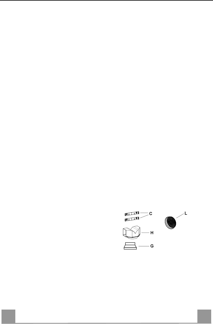
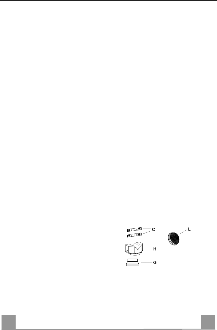
COMPONENTI
- 2 staffe di fissaggio C
- 1 flangia di riduzione G
- 1 raccordo filtrante H
- 2 filtri al carbone attivo L (facoltativo)
IT
9
9
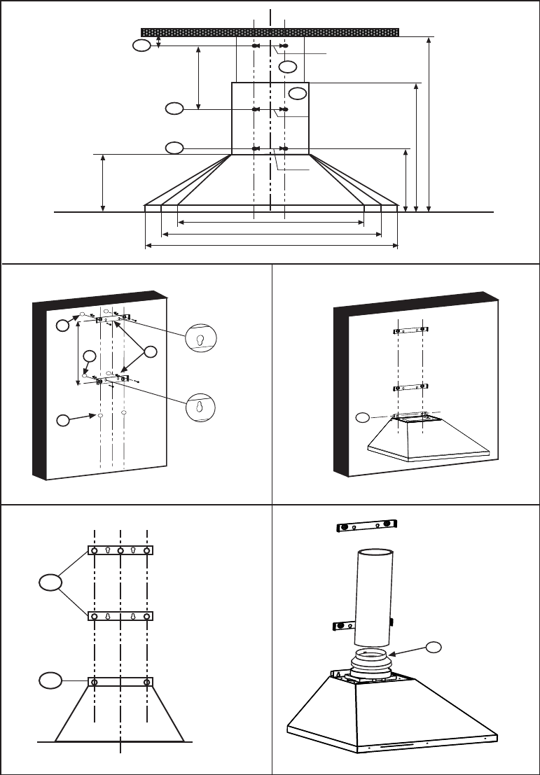
INSTALLAZIONE
La cappa deve essere montata al centro del piano cottura. La distanza minima tra il piano di
cottura e la superficie inferiore della cappa deve essere di 650mm.
Per il montaggio della cappa procedere nel modo seguente:
1) Praticare n°6 fori (X1-X2-J) Ø 8mm rispettando le quote indicate in fig. 1.
2) Per i vari montaggi utilizzare le viti e i tasselli espansione in dotazione.
3) Bloccare le staffe C (fig. 2) alla parete nei fori X1-X2.
4) Fissare la cappa alla parete nei fori esterni J1 e J2 (fig. 3).
5) Montaggio ASPIRANTE o FILTRANTE:
• ASPIRANTE
Per installazione in Versione Aspirante collegare la Cappa alla tubazione di uscita per mezzo
di un tubo rigido o flessibile di ø150 o 120 mm, la cui scelta è lasciata all'installatore.
• Per collegamento con tubo ø120 mm, inserire la Flangia di riduzione 9sull’Uscita del
Corpo Cappa.
• Fissare il tubo con adeguate fascette stringitubo. Il materiale occorrente non è in dotazione.
• Togliere eventuali Filtri Antiodore al Carbone attivo.
• FILTRANTE (VERSIONE OPZIONALE)
- Inserire il Raccordo filtrante H (fig. 6).
- Montare i filtri carbone attivo L (fig. 7) bloccarli ruotando in senso orario (circa 10°) fino
allo scatto di arresto. Per lo smontaggio eseguire le operazioni all'inverso.
Montaggio Camini
6) Fissare il camino superiore A (fig. 8) alle staffe C (fig. 2/ fig. 8) utilizzando n°4 viti autofi-
lettanti Ø2,9mm in dotazione. La distanza tra i fori di fissaggio X1 e X2 viene stabilita dal-
l'altezza del camino superiore H .
7) Applicare frontalmente il camino inferiore B (fig. 9) allargando leggermente le due parti
laterali e poi inserirlo nella cappa (fig. 9).
IT
1
0
10
USO - MANUTENZIONE
USO
Vi raccomandiamo di far funzionare l'apparecchio poco prima di procedere alla cottura di
qualsiasi vivanda e di lasciar funzionare lo stesso ancora per 15 minuti dopo la cottura, co-
munque fin tanto che ogni odore sia scomparso.
1) Quadro comandi con interruttori
- Un interruttore che comanda l'accensione dell'impianto di illuminazione.
- Un interruttore per commutare le tre velocità d'esercizio.
- Una generica spia di segnalazione motore in funzione.
2) Quadro comandi con pulsanti
- Un pulsante che comanda l'accensione del motore in prima velocità, adatta ad un ricambio
d'aria continuo particolarmente silenzioso, in presenza di pochi vapori di cottura.
- Un pulsante che comanda il motore in seconda velocità, adatta alla maggior parte delle
condizioni di uso, dato l'ottimo rapporto tra portata d'aria trattata e livello di rumorosità.
- Un pulsante che comanda il motore in terza velocità, adatta a fronteggiare le massime e-
missioni di vapori di cottura, anche per tempi prolungati.
- Un pulsante che comanda l'accensione dell'impianto di illuminazione.
MANUTENZIONE
N.B. Prima di qualsiasi intervento di manutenzione, riparazione ed eventuale sostituzione lam-
pade, disinserire l'apparecchio dalla rete elettrica.
1. Illuminazione
E' costituita da due lampade da 40 W. Per effettuare una sostituzione operare come segue
(fig.10):
Togliere uno dei perni ai lati della plafoniera. Far scorrere il vetro verso il lato senza perno
fino a liberare la punta opposta, quindi tirare leggermente verso il basso.Sostituire le lam-
pade e rimontare il vetro con sequenza opposta.
2. Filtri
Ad intervalli più o meno frequenti, secondo l'uso della cappa, comunque una volta ogni 2
mesi, i filtri metallici debbono essere smontati e lavati con acqua calda saponosa, o diret-
tamente lavati in lavastoviglie e rimontati asciugati (i filtri in carbone attivo non devono
essere assolutamente lavati e devono essere sostituiti ogni 2 mesi).
3. Pulizia
Per la pulizia esterna della cappa utilizzare un panno umido con alcool o con prodotti adat-
ti reperibili in commercio. Evitate di usare degli elementi abrasivi.
IMPORTANTE: L'impiego di fiamma libera è dannoso ai filtri, pertanto è sconsigliato di
lasciare acceso un bruciatore a gas senza pentola. È obbligatorio mettere in atto le opera-
zioni di pulizia della cappa o dei filtri, non che la loro periodica sostituzione secondo le
nostre istruzioni per evitare pericoli di incendio.
ATTENZIONE: La casa produttrice non risponde degli eventuali danni causati dalla
mancata manutenzione del filtro antigrasso (lavaggio ogni due mesi), sostituzione del filtro
carbone ed il non rispetto delle istruzioni di montaggio ed allacciamento elettrico sopra de-
scritte.
EN
1
1
11
WARNINGS - COMPONENTS
WARNINGS
This appliance has been designed for use as either an EXTRACTION (ducting to the outside)
or RECIRCULATION (filtering) hood. The measurements contained on the drawings in this
booklet refer to two models of cooker hood. Therefore, it is essential that you refer to the cor-
rect drawing when taking measurements for installation.
- The minimum distance between the cooking surface and the metal grease filters on the
underside of the hood must be 650mm.
- This cooker hood must be installed in accordance with the installation instructions and
all requirements must be adhered to.
- If the room where the cooker hood is to be used contains a fuel burning appliance such
as a central heating boiler then its flue must be of the room sealed or balance flue type.
- If other types of flue or appliances are fitted ensure that there is an adequate supply of
air to the room.
- When the cooker hood is used in conjunction with appliances supplied with energy
other than electricity, the negative pressure in the room must not exceed 0.4 mbar to
prevent fumes being drawn back into the room by the hood.
- The ducting system for this appliance must not be connected to any ventilation system
which is being used for any other purpose.
- The ducting system for this appliance must not be connected to any existing ventilation
system which is being used for any other purpose.
- Do not leave naked flames or carry out flambè cooking under this cooker hood.
CONNECTION TO THE MAINS WARNING: DOUBLE INSULATED DO NOT EARTH
Before connecting to the mains supply ensure the mains voltage corresponds to the voltage on
the rating plate inside the hood.
This appliance is fitted with a 2 core mains cable and must be permanently connected to the
electricity supply via a double-pole switch having 3mm minimum contact gap on each pole.
COMPONENTS
- 2 No Wall Brackets C
- 1 No 150-120mm Ducting Spigot G
- 1 No Air Outlet Connection H
- 2 No Charcoal Filters L (Optional)
EN
1
2
12
INSTALLATION
The cooker hood must be installed centrally over a cooking appliance. The minimum distance
between the cooking surface and the metal grease filters on the underside of the hood must be
at least 650mm.
To install the hood proceed as follows:
1) Drill six 8mm diameter holes at X1-X2-J and insert the plastic rawl plugs supplied as illus-
trated in fig. 2 ensuring the brackets are fitted as shown in the blow up.
2) Secure the two brackets C to the wall inserting two of the screws supplied through the two
holes on line X1-X2 as illustrated in fig. 2.
3) Slide the canopy down the wall to locate the key hole over the washer then secure the can-
opy to the wall by inserting two of the screws supplied through the two outer holes in the
rim of the canopy J1 and J2 as illustrated in fig. 3.
4) EXTRACTION OR RECIRCULATION INSTALLATION:
• EXTRACTION (DUCTED)
When installing the ducted version, connect the hood to the chimney using either a flexible or
rigid pipe ø 150 or 120 mm, the choice of which is left to the installer.
• To install a ø 120 mm air exhaust connection, insert the reducer flange 9 on the hood body
outlet.
• Fix the pipe in position using sufficient pipe clamps (not supplied).
• Remove any activated charcoal filters.
• RECIRCULATION (FILTERED)
• When the hood is fitted in the recirculation mode the Air Outlet Connection H should be
fitted as illustrated in fig. 6.
• Fit the (optional) charcoal filters by repeating the following operation on each side of the
motor housing. Place the two key hole slots in the filter L and turn the filter clockwise to
lock the filter in position as illustrated in fig. 7.
WARNING: It is a possible fire hazard if the metal grease filters are not cleaned and the
charcoal filters replaced regularly.
Fitting The Chimney
5) FITTING THE CHIMNEY UPPER
To fit the upper chimney A, place the top edge of the chimney over the bracket C as illus-
trated in fig. 8 and secure the chimney using two of the 2.9mm self tapping screws pro-
vided.
The distance H in the height between the fixing holes X1and X2 is determined by the
height of the upper chimney A.
6) FITTING THE CHIMNEY LOWER
To fit the lower chimney B, apply slight force to the two rear edges to increase the width
of the apperture, then sleeve the chimney B over the chimney A as illustrated in fig. 9.
EN
1
3
13
USE - MAINTENANCE
USE
The cooker hood functions are controlled by a series of slider or push button switches mounted
on the front of the hood and control the worktop lighting and fan motor speeds. This cooker
hood will not remove steam.
1) SLIDER SWITCHES
- A switch controls the wotktop lighting - ON/OFF.
- A switch controls the fan speeds - OFF/ON-1-2-3.
- The red neon lamp illuminates when the motor is switched ON .
2) PUSH BUTTON SWITCHES
- A switch controls the worktop lighting - ON/OFF.
- A button switches the motor OFF/ON at the low speed setting.
- A button switches the motor to the medium speed setting.
- A button switches the motor to the high speed setting.
- The red neon lamp illuminates when the motor is switched ON.
3) SPEED SETTINGS
- 1/Low should be selected when simmering or when using only one pan.
- 2/Medium should be selected for cooking when using up to four pans.
- 3/High should be selected when frying or cooking food with a strong odour.
MAINTENANCE
N.B. Before carring out any kind of maintenance, cleaning or replacing lamps, disconnect the
hood from the mains supply.
1. Lighting
Comprises two 40W bulbs. To replace the bulbs, proceed as follows (fig.10): Remove one
of the pins at the sides of the lamp cover. Slide the glass towards the side from which the
pin has been removed until the opposite edge has been freed, then pull gently downwards.
Replace the bults and fit the glass again by repeating the above operations in reverse order.
2. Filters
- The metal grease filter should be cleaned every two months or more frequently if the hood
is used consistently and can be cleaned in a dishwasher or by hand using a mild detergent
or liquid soap. When replacing, ensure that they are dry.
- The charcoal filter cannot be washed and should be replaced at least every 2 months or
more frequently if the hood is used consistently.
3. Cleaning
When cleaning the hood, it is recommended to use a damp cloth and mild liquid household
cleaner. Never use abrasive cleaning materials.
IMPORTANT: When using a gas hob in connection with the cooker hood never leave the
burners of the hob uncovered while the hood is in use or when the pans have been re-
moved. It is very important to follow all instructions for cleaning the hood and filters.
There could be a possible fire hazard if the filters are not replaced according to these in-
structions.
ATTENTION: The manufacturer declines all responsibility for any damage or injury
caused as a result of not following the instructions for installation, for maintenance and re-
placement times of filters indicated (in order to avoid a possible risk of fire when the filters
are saturated with grease).
FR
1
4
14
ATTENTION - COMPOSANTS
ATTENTION
Cet appareil a été conçu pour être employé en version ASPIRANTE (évacuation de l'air vers
l'extérieur) ou en version RECYCLAGE (air conduite vers l'intérieur).
- La distance minimum entre le plan de cuisson et la partie inférieure de la hotte doit
être au moins de 650mm.
- Il faut prévoir une aération convenable de la pièce lorsque la hotte et les appareils ali-
mentés avec énergie différente de celle éléctrique sont utilisés en même temps; la pres-
sion négative de la pièce ne doit pas dépasser 4Pa (4x10⁻⁵ bar).
- L'air recueillie ne doit pas être dirigée dans un conduit utilisé pour la décharge des
fumées des appareils alimentés avec énergie différente de celle éléctrique.
- Respecter les prescriptions des autorités compétentes relatives à la décharge de l'air à
evacuer.
- Eviter la présence de flammes libres dans l'espace au dessous de la hotte.
- La hotte a été construite avec isolement en classe II, donc il n'y a pas besoin de la relier
à la terre.
- Avant d'effectuer toutes les opérations d'entretien, débrancher l'appareil de l'alimen-
tation éléctrique.
BRANCHEMENT DU CABLE D'ALIMENTATION AU RESEAU
Avant la mise en place de l'appareil, verifier que la tension indiquée sur la plaque signalétique
fixée à l'intérieur de l'appareil corresponde à la tension de votre abitation. Fixer sur le cable
d'alimentation une fiche normalisée correspondant à la charge indiquée sur la plaquette signa-
létique; En cas de connection directe au réseau il faudra placer entre l'appareil et le réseau un
interrupteur bipolaire avec ouverture de min. 3mm entre les contacts.
L'interrupteur bipolaire doit être adaptable à la charge, et correspondre aux normes en vigueur.
COMPOSANTS
- 2 brides C
- 1 bride de réduction G
- 1 raccord filtrant H
- 2 filtres charbon actif L (optionnel)
FR
1
5
15
INSTALLATION
La hotte doit être assemblée au centre du plan de cuisson. La distance minimum entre le plan
de cuisson et la surface inférieure de la hotte doit être de 650mm.
Pour l'assemblage de la hotte procéder de la manière suivante:
1)Faire n°6 trous (X1-X2-J) de 8mm respectant les chiffres indiqués à la fig. 1.
2) Pour les différents assemblages utiliser les vis et les vis tamponnées fournies..
3) Bloquer l'étrier C (fig. 2) à la paroi dans les trous X1-X2.
4) Fixer la hotte à la paroi dans les trous J1 et J2 (fig. 3) .
5) Assemblage ASPIRANTE ou FILTRANT.
• ASPIRANTE
En cas d’installation en version aspirante, brancher la hotte à la tuyauterie de sortie via un tube
rigide ou flexible de ø 150 ou 120 mm, au choix de l’installateur.
• En cas de branchement avec un tube de ø120 mm, insérer le flasque de réduction 9 sur la
sortie du corps de la hotte.
• Fixer le tube par des colliers appropriés. Le matériau nécessaire n’est pas fourni.
• Retirer les éventuels filtres anti-odeur au charbon actif.
• FILTRANT (OPTION)
- Insérer le Raccord Sortie Air H (fig. 6).
- Assembler les filtres charbon actif L (fig. 7) en les centrant dans le support moteur M et
les bloquer en tournant dans sens horaire (environ 10°) jusqu'à l'arret. Pour les opérations
de démontage faire les opérations inverses.
6) Fixer la cheminée supérieure A (fig. 8) à l'étrier C (fig. 2/fig. 8) utilisant 4 vis autotarau-
deuses de Ø 2,9mm en dotation. La distance entre les alésages de fixation X1 et X2 est dé-
terminée par la hauteur de la cheminée supérieure H.
7) Appliquer frontalement la cheminée inférieure B (fig. 9) en élargissant légèrement les deux
parties latérales et l'insérer ensuite dans la hotte (fig. 9).
FR
1
6
16
UTILISATION - ENTRETIEN
UTILISATION
Nous vous recommandons de faire fonctionner l'appareil quelque temps avant de procéder à la
cuisson de n'importe quel aliment, de le laisser fonctionner encore pendant 15 minutes après la
cuisson et de toute manière tant que les odeurs n'auront pas disparu.
1) Bandeau de commandes avec interrupteurs
- Un interrupteur qui commande l'allumage de l'installation d'éclairage.
- Un interrupteur pour commuter les trois vitesses d'exercice.
- Un voyant général de signalisation moteur en service.
2) Bandeau de commandes avec touches
- Une touche qui commande l'allumage du moteur en première vitesse, indiquée pour une
circulation d'air continue particulièrement silencieuse, en présence de faibles vapeurs de
cuisson.
- Une touche qui commande le moteur en deuxième vitesse, indiquée dans la plupart des
conditions d'emploi vu l'excellent rapport entre le débit d'air traité et le niveau de bruit.
- Une touche qui commande le moteur en troisième vitesse, indiquée en cas d'importantes
émissions de vapeurs de cuisson, également pendant des périodes prolongées.
- Une touche qui commande l'allumage de l'installation d'éclairage.
ENTRETIEN
N.B. Pour n'importe quelle opération d'entretien et de réparation débranchez l'appareil.
1. Eclairage
Il est constitué par deux lampes de 40W. Pour effectuer un remplacement, suivre les ins-
tructions suivantes (fig.10): Retirer l'un des goujons qui se trouvent sur les côtés du pla-
fonnier. Faire coulisser le verre sur le côté sans le goujon, jusqu'à dégager la pointe oppo-
sée, puis tirer légèrement vers le bas. Remplacer les lampes et remonter le verre en effec-
tuant les opérations décrites ci-dessus à rebours.
2. Filtres
A des intervalles plus ou moins fréquents en fonction de leur utilisation, mais en tout cas
une fois tous les 2 mois, les filtres métalliques doivent être lavés dans le lave-vaisselle ou à
la main dans de l'eau tiède savonneuse (les filtres au charbon actif ne doivent jamais etre
lavés et doivent être remplacés tous les 2 mois).
3. Nettoyage
Pour ce qui concerne le nettoyage externe de la hotte, utiliser un chiffon humide et de l'al-
cool ou d'autres produits appropriés. N'employez pas de produits abrasifs.
IMPORTANT: Il est obligatoire d'effectuer les opérations de nettoyage de la hotte et des fil-
tres, ainsi que de les remplacer périodiquement selon nos instructions pour éviter les risques
d'incendie.
ATTENTION: Le fabricant décline toute résponsabilité pour les dommages provoqués par le
non entretien des filtres anti-graisse (nettoyage tous les 2 mois) ainsi que par le non replace-
ment périodiques des filtres à charbon et par le non respect des instructions de montage et de
branchement.
DE
1
7
17
HINWEIS - KOMPONENTEN
HINWEIS
Dieses Gerät ist sowohl für den Abluftbetrieb als auch für den Umluftbetrieb (Filterversion)
geeignet. Die Abmessungen, die in den Zeichnungen dieser Bedienungsanleitung angegeben
sind, beziehen sich auf zwei verschiedene Haubenmodelle.
Daher ist es äußerst wichtig, daß Sie die richtige Zeichnung zugrunde legen, bevor Sie die In-
stallation ausführen.
- Der Mindestabstand zwischen Kochfeld und Metallfilter an der Unterseite Ihrer Dun-
stabzugshaube muß 650 mm betragen.
- Die Dunsthaube muß genau nach den Anweisungen der Bedienungsanleitung instal-
liert werden.
- Falls in dem Raum, in dem sich die Haube befindet, gleichzeitig eine offene Feuerstelle
vorhanden ist, (z.B. ein Gas-Durchlauferhitzer, ein Kohleherd, ein offener Kamin)
muß in jedem Fall der Luftstrom durch ein hermetisch abgeschlossenes Rohr nach
draußen abgeführt werden.
- Falls ein offene Feuerstelle im gleichen Raum betrieben wird, muß für ausreichende
Luftzufuhr von außen in den Raum gesorgt werden.
- Wenn die Dunsthaube zusammen mit solchen zuvor beschriebenen Geräten, die nicht
mit Strom gespeist werden, in Betrieb ist, darf der Unterdruck keinesfalls 0,4 mbar
überschreiten, damit das Rücksaugen der Feuerstättenabgase in den Raum vermieden
wird.
- Das Abluftrohr der Haube darf keinesfalls an eine Entlüftungsleitung oder Ventilation
angeschlossen werden.
- Niemals eine große Flamme bei eingeschalteter Dunsthaube unbedeckt lassen.
- Wichtig: niemals unter dem Gerät flambieren.
NETZANSCHLUSS
Achtung: doppelte Isolierung ! Nicht an Erdung anschließen!
Bevor Sie die Haube ans Netz anschließen, ist sicherzustellen, dass die Netzspannung den
Anschlußwerten auf dem Typenschild im Inneren der Haube entspricht. Beim Anschluß der
Dunsthaube an das Wechselstromnetz ist ein zweipoliger Schalter mit einem Öffnungsweg von
wenigstens 3 mm für jeden Pol zwischenzuschalten.
KOMPONENTEN
- 2 Wandhalterungen (C) (je nach Ausführung evtl. auch nur eine Wandhalterung für oben)
- 1 gestufte Verbindungsflansche Durchmesser 120 mm auf 150 mm (G)
- 1 Luftaustritt-Anschlussstück (H)
- 2 Kohlefilter (L)(Optional)
DE
1
8
18
MONTAGE
Die Haube muss mittig über dem Kochfeld installiert werden. Der Mindetsabstand zwischen
Kochfeld und Fettfilter an der Unterseite der Haube muss mindestens 650 mm betragen.
Die Installation verläuft wie folgt :
1) Bohren sie sechs Löcher mit 8mm Durchmesser in den Punkten X1, X2, J. Stecken Sie die
Wand-Dübel in die vorgebohrten Löcher gemäß Abb. 2 und vergewissern Sie sich, daß die
beiden Wandhalter angebracht sind, genau wie in der Zeichnung dargestellt.
2) Schrauben Sie die Wandhalter (C) mit den beiden passenden Schrauben in den Löchern
X1 und X2, Abb.2, fest.
3) Bringen Sie die Haube so an der Wand an, daß das Loch für die Befestigungsschraube ge-
nau über der Unterlegscheibe liegt und schrauben Sie die beiden mitgelieferten Schrauben
in die Bohrlöcher J1 und J2, wie in Abb. 3.
4) Um unbeabsichtigtes Aushängen der Haube zu vermeiden, verriegeln Sie die Installation
für Abluft- und Umluftbetrieb:
• ABLUFTBETRIEB
Bei Abluftbetrieb kann die Haube vom Installateur wahlweise mittels Rohr oder Schlauch (ø
150 oder 120 mm) an die Außenrohrleitung angeschlossen werden.
• Bei Verwendung eines Anschlussrohres ø 120 den Reduzierflansch 9 am Haubenaustritt
anbringen.
• Das Rohr mit geeigneten Rohrschellen fixieren. Das hierzu erforderliche Material wird
Gebruikershandleiding.com neemt misbruik van zijn services uitermate serieus. U kunt hieronder aangeven waarom deze vraag ongepast is. Wij controleren de vraag en zonodig wordt deze verwijderd.
Product:
Spelregels forum
Om tot zinvolle vragen te komen hanteren wij de volgende spelregels:
lees eerst de handleiding door;
controleer of uw vraag al eerder door iemand anders is gesteld;
probeer uw vraag zo duidelijk mogelijk te stellen;
heeft u een probleem en al geprobeerd om dit op te lossen, vermeld dit erbij aub;
heeft u een oplossing gekregen van een bezoeker dan horen wij dat graag in dit forum;
wilt u een reactie geven op een vraag of antwoord, gebruik dan niet dit formulier maar klik op de knop 'reageer op deze vraag';
uw vraag wordt direct op de website gezet; vermijd daarom persoonlijke gegevens in te vullen;
Belangrijk! Als er een antwoord wordt gegeven op uw vraag, dan is het voor de gever van het antwoord nuttig om te weten als u er wel (of niet) mee geholpen bent! Wij vragen u dus ook te reageren op een antwoord.
Belangrijk! Antwoorden worden ook per e-mail naar abonnees gestuurd. Laat uw emailadres achter op deze site, zodat u op de hoogte blijft. U krijgt dan ook andere vragen en antwoorden te zien.
Abonneren
Abonneer u voor het ontvangen van emails voor uw Smeg KSED-61 X-1 bij:
nieuwe vragen en antwoorden
nieuwe handleidingen
U ontvangt een email met instructies om u voor één of beide opties in te schrijven.
Ontvang uw handleiding per email
Vul uw emailadres in en ontvang de handleiding van Smeg KSED-61 X-1 in de taal/talen: Nederlands, Duits, Engels, Frans, Italiaans als bijlage per email.
De handleiding is 0,62 mb groot.
U ontvangt de handleiding per email binnen enkele minuten. Als u geen email heeft ontvangen, dan heeft u waarschijnlijk een verkeerd emailadres ingevuld of is uw mailbox te vol. Daarnaast kan het zijn dat uw internetprovider een maximum heeft aan de grootte per email. Omdat hier een handleiding wordt meegestuurd, kan het voorkomen dat de email groter is dan toegestaan bij uw provider.
Stel vragen via chat aan uw handleiding
Stel uw vraag over deze PDF
Uw handleiding is per email verstuurd. Controleer uw email
Als u niet binnen een kwartier uw email met handleiding ontvangen heeft, kan het zijn dat u een verkeerd emailadres heeft ingevuld of dat uw emailprovider een maximum grootte per email heeft ingesteld die kleiner is dan de grootte van de handleiding.
Er is een email naar u verstuurd om uw inschrijving definitief te maken.
Controleer uw email en volg de aanwijzingen op om uw inschrijving definitief te maken
U heeft geen emailadres opgegeven
Als u de handleiding per email wilt ontvangen, vul dan een geldig emailadres in.
Uw vraag is op deze pagina toegevoegd
Wilt u een email ontvangen bij een antwoord en/of nieuwe vragen? Vul dan hier uw emailadres in.