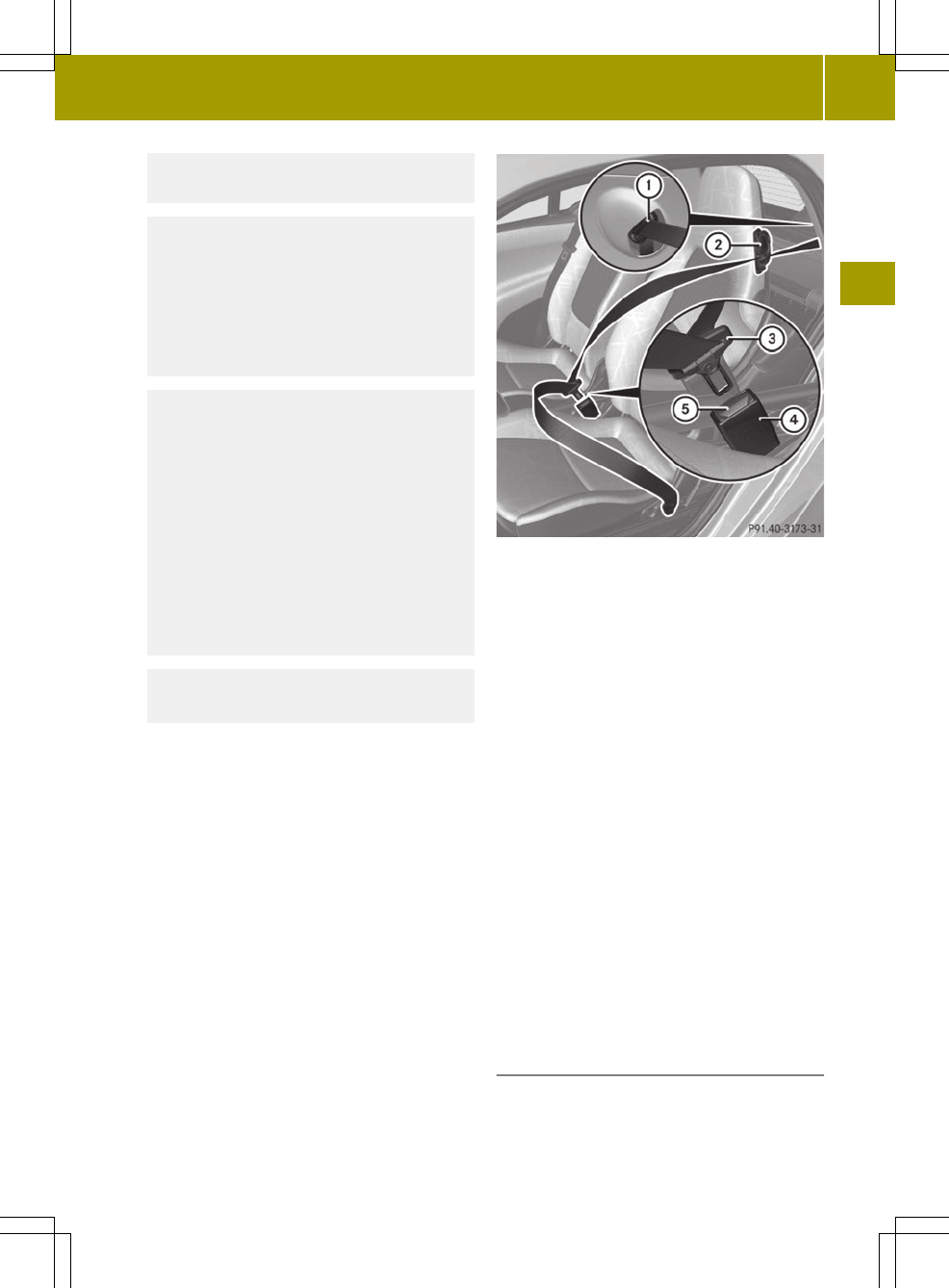
vated. The seat belt is now locked. Push
down on child restraint to take up any
slack.
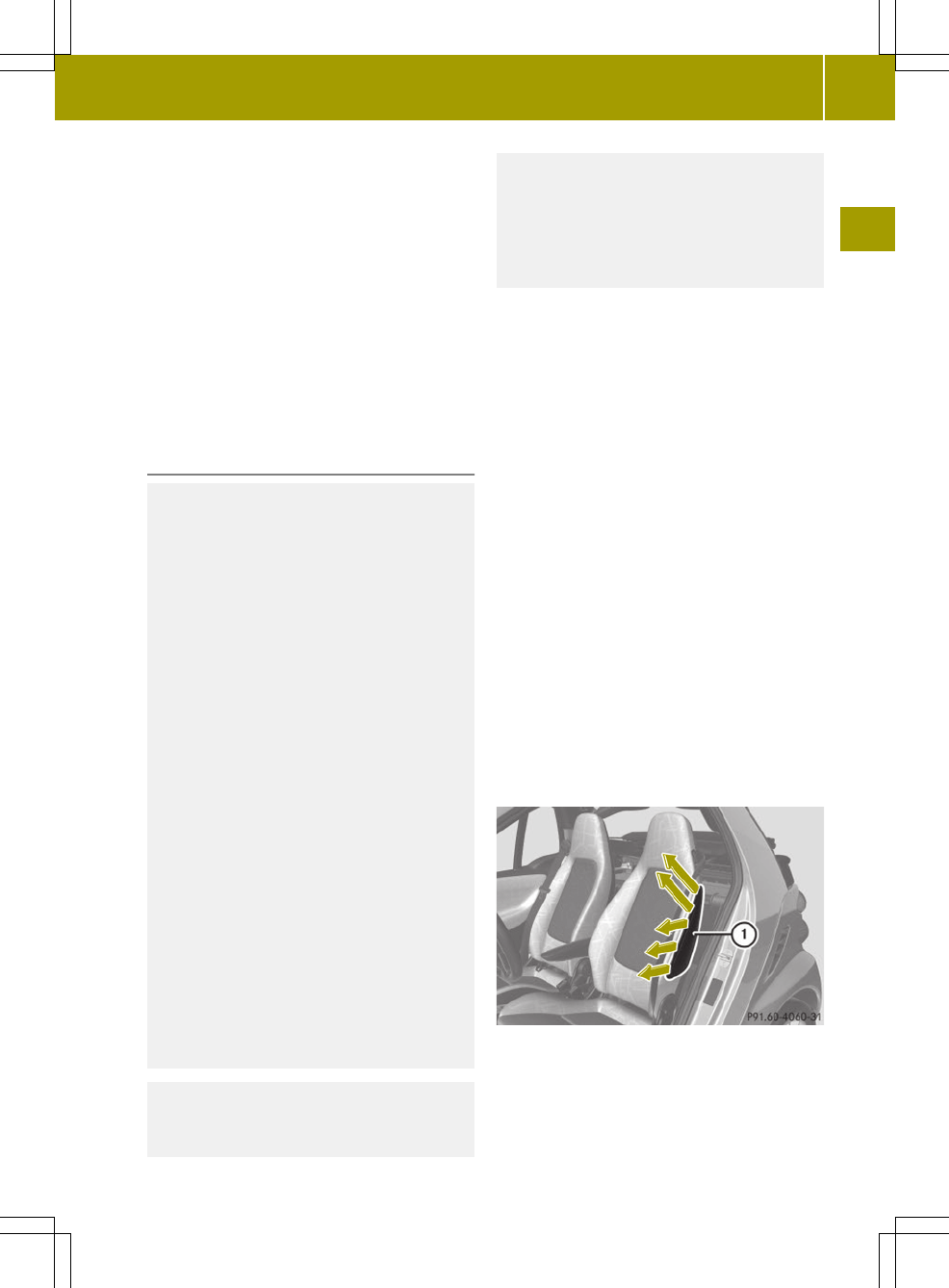
To deactivate, release seat belt buckle and
let seat belt retract completely. To deac-
tivate the special seat belt retractor for
the passenger seat, the passenger seat must
be in the most backward position. The seat
belt can again be used in the usual manner.
G
WARNING
Never release the seat belt buckle while the
vehicle is in motion, since the special seat
belt retractor will be deactivated.
The use of infant or child restraints is
required by law in all 50 states, the Dis-
trict of Columbia, the U.S. territories, and
all Canadian provinces and territories.
Infants and small children should be seated
in an appropriate infant or child restraint
system properly secured in accordance
with the manufacturer’s instructions for
the child restraint, that complies with U.S.
Federal Motor Vehicle Safety Standards 213
and 225 and Canadian Motor Vehicle Safety
Standards 213, 213.1 and 213.2.
A statement by the child restraint manu-
facturer of compliance with these stand-
ards can be found on the instruction label
on the restraint and in the instruction
manual provided with the restraint.
When using any infant restraint, toddler
restraint, or booster seat be sure to care-
fully read and follow all manufacturer’s
instructions for installation and use.
Please read and observe warning labels
affixed to the inside of the vehicle and to
infant or child restraints.
G
WARNING
Children 12 years old and under must be
seated and properly secured in an appro-
priately sized infant restraint, toddler
restraint, or booster seat recommended for
the size and weight of the child.
The infant or child restraint must be prop-
erly secured with the vehicle’s seat belt
fully in accordance with the child seat
manufacturer’s instructions.
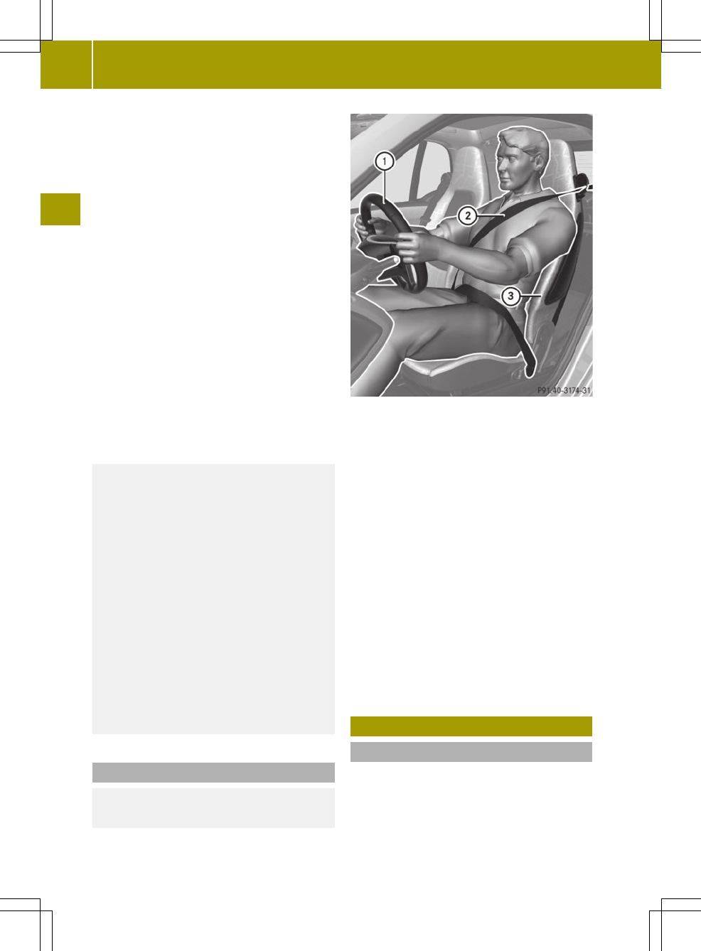
Occupants, especially children, should
never place their bodies or lean their
heads in the area of the door where the
head-thorax air bags (cabriolet), window
curtain air bags (coupé) and thorax-pelvis
air bags (coupé) inflates. This could result
in serious injuries or death should the
head-thorax air bags (cabriolet), window
curtain air bags (coupé) and thorax-pelvis
air bags (coupé) be triggered. Always sit as
upright as possible, properly use the seat
belt and use an appropriately sized infant
restraint, toddler restraint, or booster
seat recommended for the size and weight
of the child.
Children can be killed or seriously injured
by an inflating air bag. Note the following
important information when circumstances
require you to place a child in the
passenger seat:
R
Your vehicle is equipped with air bag
technology designed to turn off the
passenger front air bag in your vehicle
when the Occupant Classification System
senses the weight of a typical
12‑month‑old child or less along with the
weight of an appropriate child restraint
on the passenger seat.
R
A child in a rear-facing child restraint
on the passenger seat may be seriously
injured or even killed if the passenger
front air bag inflates in a collision.
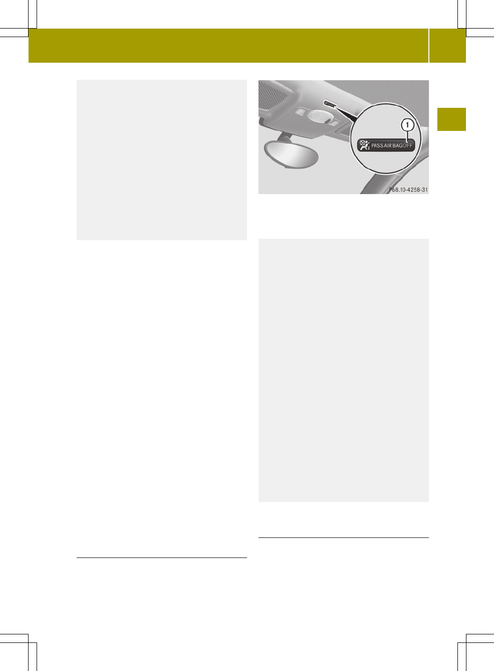
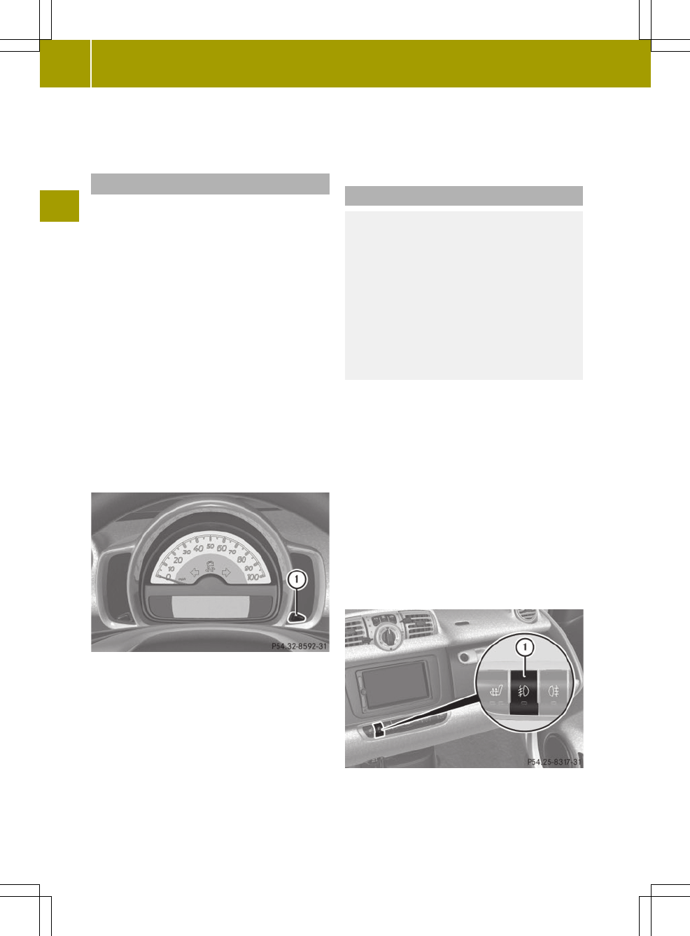
R
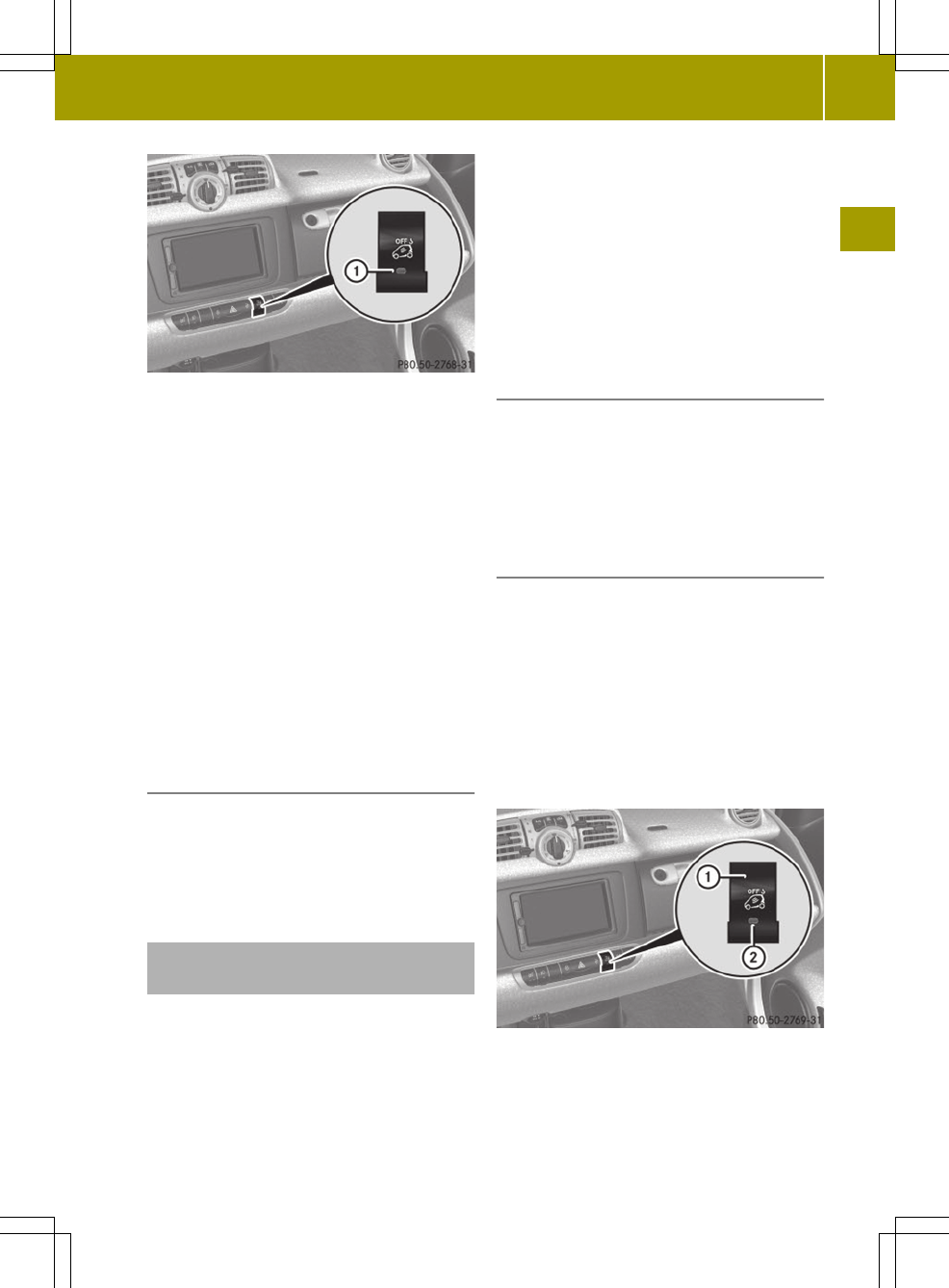
If you install a rear-facing child
restraint on the passenger seat, make
sure the 40indicator lamp
is illuminated, indicating that the
passenger front air bag is deactivated.
Should the 40indicator
lamp not illuminate or go out while the
restraint is installed, please check
installation. Periodically check the
40indicator lamp while
Occupant safety
43
>> Safety.
Z