The vehicle identification number - VIN (vehicle body number) is stamped into the
engine compartment on the right hand shock absorber dome. This number is also
located on a sign on the lower left hand edge below the windscreen (together with
a VIN bar code).
Engine number
The engine number is stamped into the engine block.
Type plate (production plate)
Is located on the left middle pillar of the bodywork.
Homologation sign
The homologation sign is located on the lock carrier. Vehicles for certain countries
do not have an homologation sign.
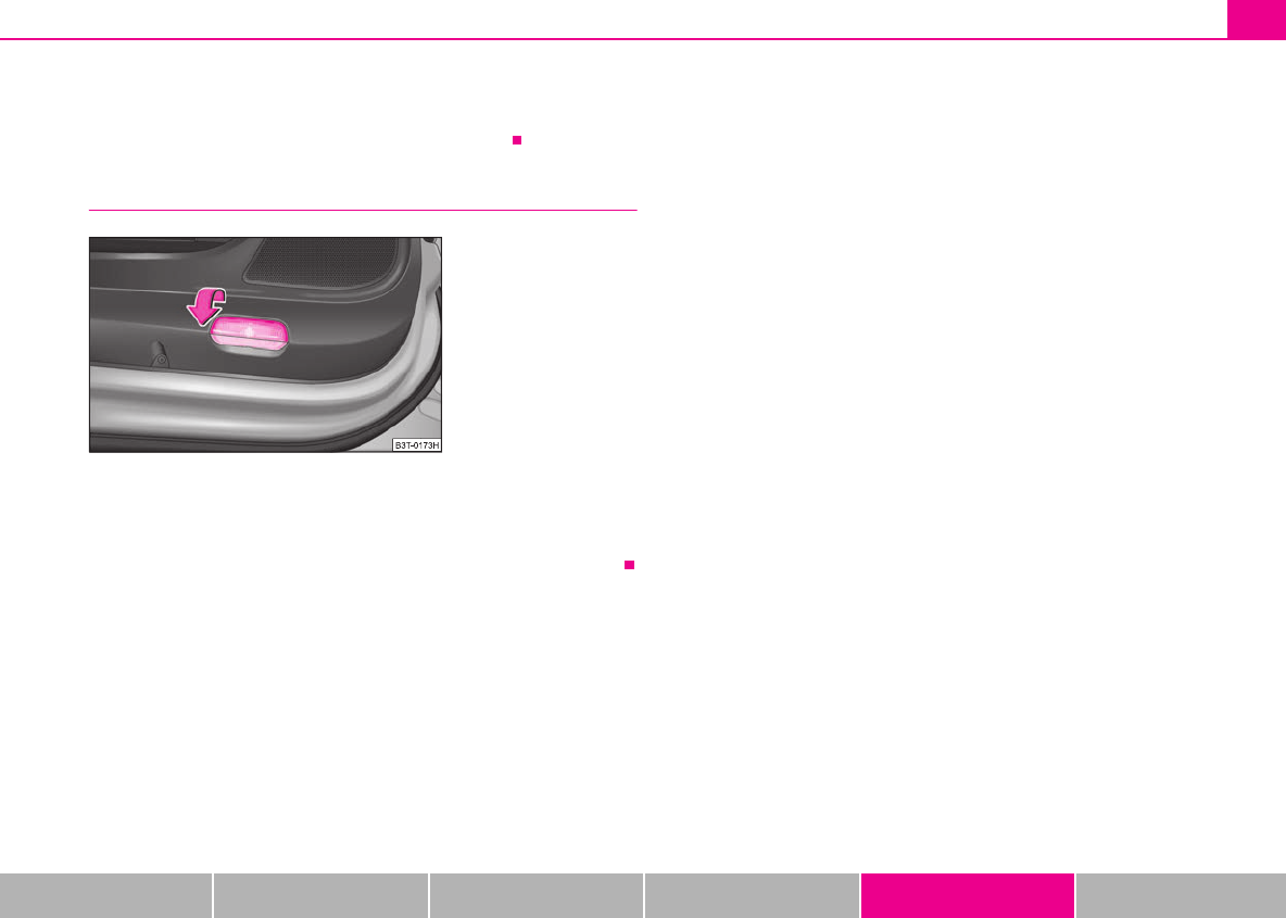
Sticker on inside of fuel filler flap
The sticker is affixed to the inside of the fuel filler flap. The sticker contains the
following data:
•The prescribed types of fuel,
•Tyre size,
•Tyre pressure.
Fuel consumption according to the regulations
(99/100/EU)
Depending on the range of the special equipment, style of driving, traffic situation,
weather influences and vehicle condition, the consumption values which in prac-
tice result when using the vehicle can deviate from the indicated values.
Urban traffic
The consumption measurement in urban traffic begins with starting of the cold
engine. Afterwards the normal urban traffic is simulated.
Non-urban traffic
For the consumption measurement in non-urban traffic the vehicle, as in daily
motoring, is accelerated and braked several times in all gears. The vehicle speed
changes within the range from 0 to 120 km/h.
Combined traffic
The consumption value in the combined traffic consists of 37% from the value for
the urban traffic and of 63% from the value for the non-urban traffic.
Note
•Please note that the information stated in the official vehicle registration
documents always takes priority.
A
1
A
2
A
3
A
4
A
5
NKO
B6
20
.
book
Page
256
Wednesday
,
March
26
,
2008
3:15
PM
Technical Data257
Using the systemSafetyDriving TipsGeneral MaintenanceBreakdown assistanceTechnical Data
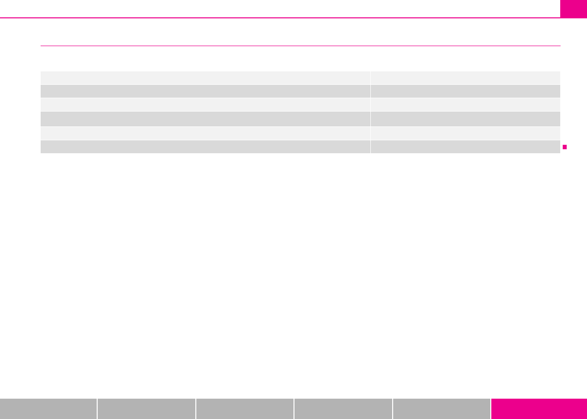
Dimensions
Dimensions (mm)
Length4838
Width1817
Width including exterior mirror2009
Height
1462/1482
a)
/1447
b)
a)
The value is valid for vehicles with rough road package.
b)
The value corresponds to the status with sport chassis.
Wheel base2761
Track gauge front / rear1545/1518
NKO
B6
20
.
book
Page
257
Wednesday
,
March
26
,
2008
3:15
PM
Technical Data258
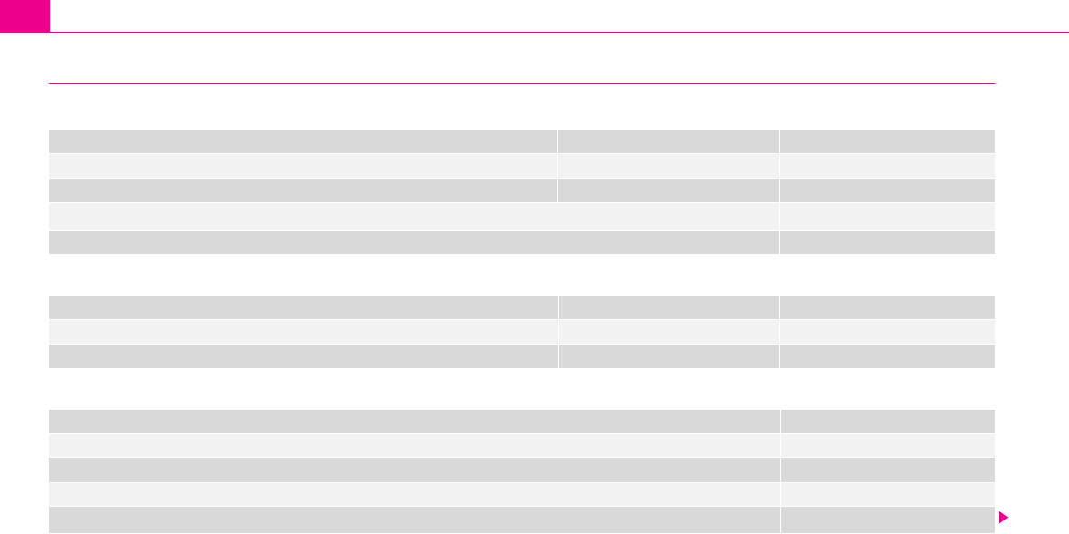
1.8 ltr./118 kW TSI - EU 4
Engine
Performances
Fuel consumption (in ltr./100 km) and CO
2
emission (in g/km)
M6
Power outputkW per rpm118/5000 - 6200
Maximum torqueNm per rpm250/1500 - 4200
Number of cylinders/Displacement (cm
3
)
4/1798
Fuel - unleaded petrol min. RON95
M6
Maximum speedkm/h220
Acceleration 0 - 100 km/hs8,6
M6
Urban10,4
Non-urban6,0
Combination7,6
CO
2
emission - combination
180
NKO
B6
20
.
book
Page
258
Wednesday
,
March
26
,
2008
3:15
PM
Technical Data259
Using the systemSafetyDriving TipsGeneral MaintenanceBreakdown assistanceTechnical Data
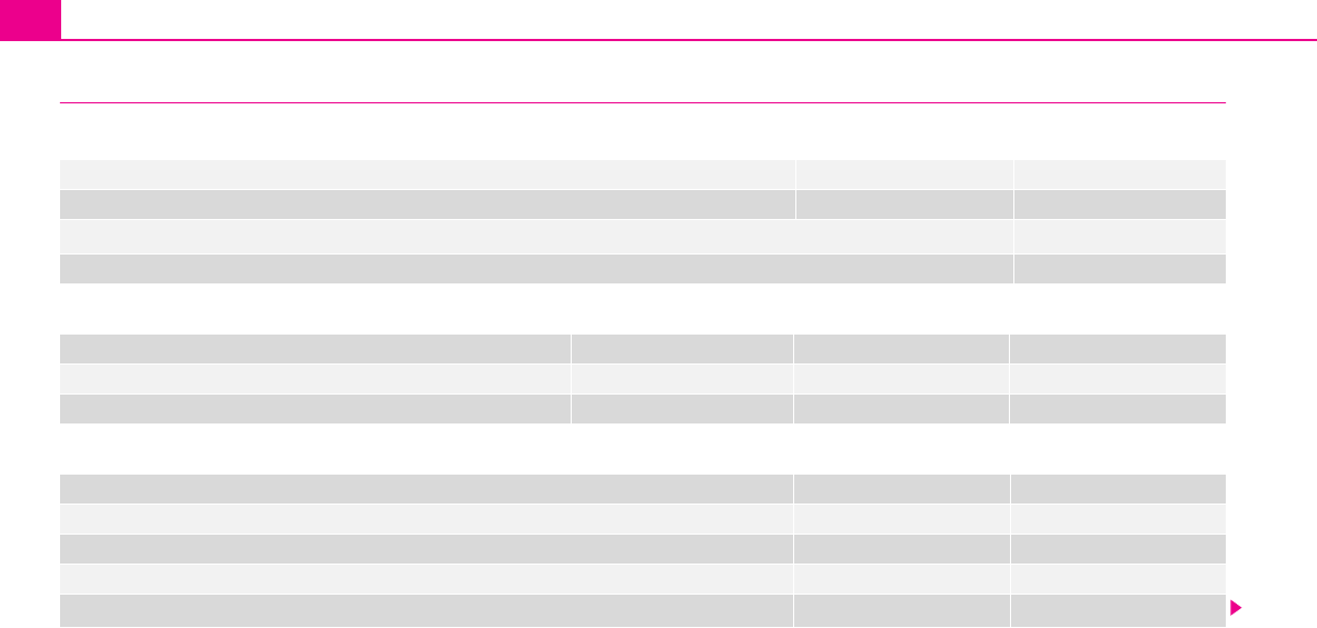
Capacities (in liter)
Weight (in kg)
Fuel tank capacity/of which spare60/9
Reservoir for windscreen washer system/ with headlight cleaning system3/5,5
Engine oil
a)
a)
Oil capacity with oil filter change. Inspect oil level when filling; do not fill up too much. The oil level must be between the markings ⇒page 211, “Check engine oil level”.
3,0
Cooling system of the vehicle5,5
M6
Permissible gross weight2074
Unloaden weight ready for work1454
Loading capacity620
Loading capacity when using the TLC545
Permissible front axle load1200
Permissible rear axle load1250
Permissible trailer load, trailer braked/unbraked
1500
a)
1700
b)
a)
Uphills up to 12 %
b)
Uphills up to 8%
NKO
B6
20
.
book
Page
259
Wednesday
,
March
26
,
2008
3:15
PM
Technical Data260
1.9 ltr./77 kW TDI PD - EU 4
Engine
Performances
Fuel consumption (in ltr./100 km) and CO
2
emission (in g/km)
Power outputkW per rpm77/4000
Maximum torqueNm per rpm250/1900
Number of cylinders/Displacement (cm
3
)
4/1896
FuelDiesel
M5
Maximum speedkm/h190
Acceleration 0 - 100 km/hs12,5
M5
Urban7,3
Non-urban4,8
Combination5,7
CO
2
emission - combination
151
NKO
B6
20
.
book
Page
260
Wednesday
,
March
26
,
2008
3:15
PM
Technical Data261
Using the systemSafetyDriving TipsGeneral MaintenanceBreakdown assistanceTechnical Data
Capacities (in liter)
Weight (in kg)
Fuel tank capacity/of which spare60/9
Reservoir for windscreen washer system/ with headlight cleaning system3/5,5
Engine oil
a)
a)
Oil capacity with oil filter change. Inspect oil level when filling; do not fill up too much. The oil level must be between the markings ⇒page 211, “Check engine oil level”.
3,8
Cooling system of the vehicle5,5
M5
Permissible gross weight2076
Unloaden weight ready for work1456
Loading capacity620
Loading capacity when using the TLC545
Permissible front axle load1200
Permissible rear axle load1250
Permissible trailer load, trailer braked/unbraked
1500
a)
1700
b)
a)
Uphills up to 12 %
b)
Uphills up to 8%
NKO
B6
20
.
book
Page
261
Wednesday
,
March
26
,
2008
3:15
PM
Technical Data262
2.0 ltr./103 kW TDI PD - EU 4
Engine
Performances
Fuel consumption (in ltr./100 km) and CO
2
emission (in g/km)
Power outputkW per rpm103/4000
Maximum torqueNm per rpm320/1800-2500
Number of cylinders/Displacement (cm
3
)
4/1968
FuelDiesel
M6DQ6
Maximum speedkm/h207205
Acceleration 0 - 100 km/hs10,210,2
M6DQ6
Urban7,58,9
Non-urban5,05,5
Combination5,96,8
CO
2
emission - combination
155177
NKO
B6
20
.
book
Page
262
Wednesday
,
March
26
,
2008
3:15
PM
Technical Data263
Using the systemSafetyDriving TipsGeneral MaintenanceBreakdown assistanceTechnical Data
Capacities (in liter)
Weight (in kg)
Fuel tank capacity/of which spare60/9
Reservoir for windscreen washer system/ with headlight cleaning system3/5,5
Engine oil
a)
a)
Oil capacity with oil filter change. Inspect oil level when filling; do not fill up too much. The oil level must be between the markings ⇒page 211, “Check engine oil level”.
Gebruikershandleiding.com neemt misbruik van zijn services uitermate serieus. U kunt hieronder aangeven waarom deze vraag ongepast is. Wij controleren de vraag en zonodig wordt deze verwijderd.
Product:
Spelregels forum
Om tot zinvolle vragen te komen hanteren wij de volgende spelregels:
lees eerst de handleiding door;
controleer of uw vraag al eerder door iemand anders is gesteld;
probeer uw vraag zo duidelijk mogelijk te stellen;
heeft u een probleem en al geprobeerd om dit op te lossen, vermeld dit erbij aub;
heeft u een oplossing gekregen van een bezoeker dan horen wij dat graag in dit forum;
wilt u een reactie geven op een vraag of antwoord, gebruik dan niet dit formulier maar klik op de knop 'reageer op deze vraag';
uw vraag wordt direct op de website gezet; vermijd daarom persoonlijke gegevens in te vullen;
Belangrijk! Als er een antwoord wordt gegeven op uw vraag, dan is het voor de gever van het antwoord nuttig om te weten als u er wel (of niet) mee geholpen bent! Wij vragen u dus ook te reageren op een antwoord.
Belangrijk! Antwoorden worden ook per e-mail naar abonnees gestuurd. Laat uw emailadres achter op deze site, zodat u op de hoogte blijft. U krijgt dan ook andere vragen en antwoorden te zien.
Abonneren
Abonneer u voor het ontvangen van emails voor uw Skoda Superb - 2008 bij:
nieuwe vragen en antwoorden
nieuwe handleidingen
U ontvangt een email met instructies om u voor één of beide opties in te schrijven.
Ontvang uw handleiding per email
Vul uw emailadres in en ontvang de handleiding van Skoda Superb - 2008 in de taal/talen: Engels als bijlage per email.
De handleiding is 19,12 mb groot.
U ontvangt de handleiding per email binnen enkele minuten. Als u geen email heeft ontvangen, dan heeft u waarschijnlijk een verkeerd emailadres ingevuld of is uw mailbox te vol. Daarnaast kan het zijn dat uw internetprovider een maximum heeft aan de grootte per email. Omdat hier een handleiding wordt meegestuurd, kan het voorkomen dat de email groter is dan toegestaan bij uw provider.
Uw handleiding is per email verstuurd. Controleer uw email
Als u niet binnen een kwartier uw email met handleiding ontvangen heeft, kan het zijn dat u een verkeerd emailadres heeft ingevuld of dat uw emailprovider een maximum grootte per email heeft ingesteld die kleiner is dan de grootte van de handleiding.
Er is een email naar u verstuurd om uw inschrijving definitief te maken.
Controleer uw email en volg de aanwijzingen op om uw inschrijving definitief te maken
U heeft geen emailadres opgegeven
Als u de handleiding per email wilt ontvangen, vul dan een geldig emailadres in.
Uw vraag is op deze pagina toegevoegd
Wilt u een email ontvangen bij een antwoord en/of nieuwe vragen? Vul dan hier uw emailadres in.