Maximum permissible towed weight (towing vehicle and trailer)
Maximum permissible front axle load
Maximum permissible rear axle load
Vehicle identification number (VIN)
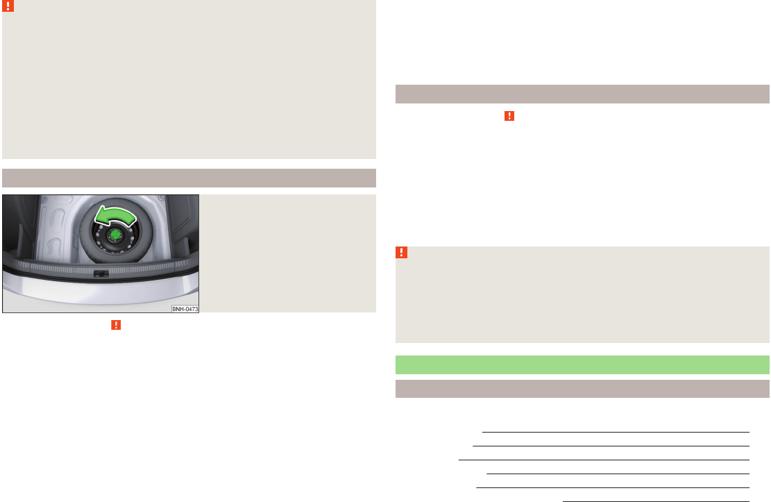
The vehicle identification number - VIN (vehicle body number) is stamped into
the engine compartment on the right hand suspension strut dome. This num-
ber is also located on a sign on the lower left hand edge below the windscreen
(together with a VIN bar code), and on the type plate.
Engine number
The engine number (three-digit identifier and serial number) is stamped on the
engine block.
Supplementary Information (applies to Russia)
The full type approval number of the means of transport is indicated in the
registration documents.
WARNING
Do not exceed the specified maximum permissible weights – risk of acci-
dent and damage!
1
2
3
4
5
6
7
8
9
177
Technical data
Operating weight and payload
Operating weight
This value represents the minimum operating weight without additional
weight-increasing equipment such as air conditioning system, spare wheel, or
trailer hitch.
The specified operating weight is for orientation purposes only.
The operating weight also contains the weight of the driver (75 kg), the weight
of the operating fluids, the tool kit, and a fuel tank filled to 90 % capacity.
Operating weight of the vehicle » page 181, Vehicle-specific details per en-
gine type.
Payload
It is possible to calculate the approximate maximum payload from the differ-
ence between the permissible total weight and the operating weight.
The payload consists of the following weights.
›
The weight of the passengers.
›
The weight of all items of luggage and other loads.
›
The weight of the roof, including the roof rack system.
›
The weight of the equipment that is excluded from the operating weight.
›
Trailer drawbar load when towing a trailer (max. 50 kg).
Note
If required, you can find out the precise weight of your vehicle at a specialist
garage.
Measurement of fuel consumption and CO
2
emissions according to
ECE Regulations and EU Directives
The data on fuel consumption and CO
2
emissions were not available at the
time of going to press.
The data on fuel consumption and CO
2
emissions are given on the ŠKODA
websites or in the sales and technical vehicle documentation.
The measurement of the intra-urban cycle begins with a cold start of the en-
gine. Afterwards urban driving is simulated.
In the extra-urban driving cycle, the vehicle is accelerated and decelerated in
all gears, corresponding to daily routine driving conditions. The driving speed
varies between 0 and 120 km/h.
The calculation of the combined fuel consumption considers a weighting of
about 37 % for the intra-urban cycle and 63 % for the extra-urban cycle.
Note
■
The fuel consumption and emission levels given on the ŠKODA websites or in
the commercial and technical vehicle documentation have been established in
accordance with rules and under conditions that are set out by legal or techni-
cal rules for the determination of operational and technical data of motor vehi-
cles.
■
Depending on the extent of the equipment, the driving style, traffic condi-
tions, weather influences and vehicle condition, consumption values can in
practice result in fuel economy figures in the use of the vehicle that differ from
the fuel consumption values listed on the ŠKODA websites or in the commer-
cial and technical vehicle documentation.
178
Technical data
Dimensions
Fig. 163 Principle sketch: Vehicle dimensions
Vehicle dimensions for operating weight without driver (in mm)
» Fig. 163SpecificationValue
A
Height
Basic dimension1461/1488
a)
Vehicles with an off-road package.1474/1500
a)
B
Front track
Basic dimension1457
For vehicles fitted with the 1.2 l/55 kW MPI and 1.2 l/63 kW TSI engines and 14"
wheel rims.
1463
C
Width1706
D
Rear track
Basic dimension1494
For vehicles fitted with the 1.2 l/55 kW MPI and 1.2 l/63 kW TSI engines and 14"
wheel rims.
1500
E
Width including exterior mirror1940
F
Clearance
Basic dimension136
Vehicles with an off-road package.143
G
Wheel base2602
H
Length4483
a)
Valid for vehicles with the Amundsen+ navigation system.
179
Technical data
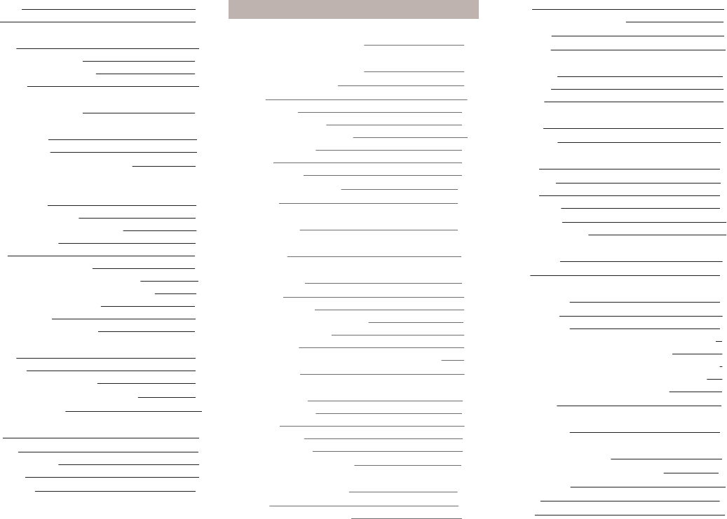
Angle
Fig. 164
Principle sketch: Departure an-
gle
Angle» Fig. 164
Overhang angle, front
Overhang angle, rear
Departure angle
The values shown indicate the maximum incline of an embankment, up which
the vehicle can drive at a slow speed without collision of the bumper or under-
body.
The values listed correspond to the maximum axle load, front or back.
Overhang angle (°)
Overhang angle, frontOverhang angle, rear
1412.3
A
B
180
Technical data
Vehicle-specific details per engine type
The specified values have been determined in accordance with rules and under conditions set out by legal or technical requirements for determining operational
and technical data for motor vehicles.
1.2 l/55 kW MPI engine
Output (kW at rpm)Maximum torque (Nm at rpm)Number of cylinders/displacement (cm
3
)
55/5400112/37503/1198
Performance and WeightsMG5
Top speed (km/h)175
Acceleration 0 - 100 km/h (s)13.9
Operating weight - minimal (kg)1135
Permissible trailer load, braked (kg)
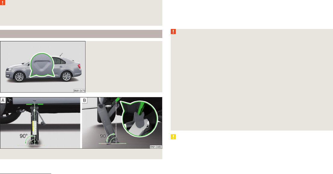
Increases up to 12 %750
Increases up to 8 %950
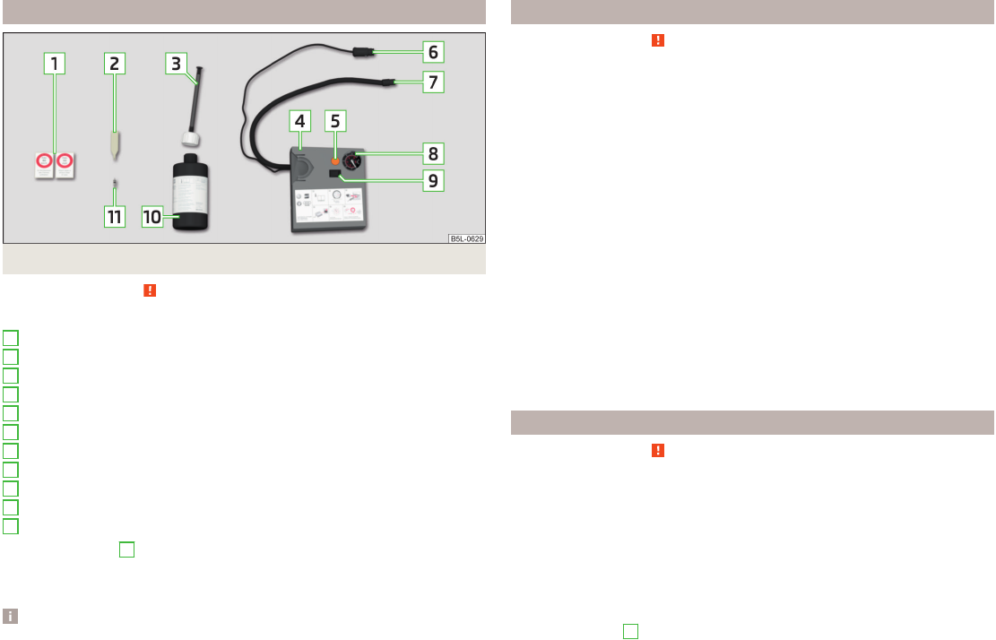
Permissible trailer load, unbraked (kg)560
1.2 ltr./63 kW TSI engine
Output (kW at rpm)Maximum torque (Nm at rpm)Number of cylinders/displacement (cm
3
)
63/4800160/1500-35004/1197
Performance and WeightsMG5
Top speed (km/h)183
Acceleration 0 - 100 km/h (s)11.8
Operating weight - minimal (kg)1155
Permissible trailer load, braked (kg)
Increases up to 12 %900
Increases up to 8 %1100
Permissible trailer load, unbraked (kg)570
181
Technical data
1.2 ltr./77 kW TSI engine
Output (kW at rpm)Maximum torque (Nm at rpm)Number of cylinders/displacement (cm
3
)
77/5000175/1550-41004/1197
Performance and WeightsMG6
Top speed (km/h)195
Acceleration 0 - 100 km/h (s)10.3
Operating weight - minimal (kg)1175
Permissible trailer load, braked (kg)
Increases up to 12 %1100
Increases up to 8 %1200
Permissible trailer load, unbraked (kg)580
1.4 ltr./90 kW TSI engine
Output (kW at rpm)Maximum torque (Nm at rpm)Number of cylinders/displacement (cm
3
)
90/5000200/1500-40004/1390
Performance and WeightsDSG7
Top speed (km/h)206
Acceleration 0 - 100 km/h (s)9.5
Operating weight - minimal (kg)1230
Permissible trailer load, braked (kg)
Increases up to 12 %1200
Increases up to 8 %1200
Permissible trailer load, unbraked (kg)610
182
Technical data
1.6 l/77 kW MPI engine
Output (kW at rpm)Maximum torque (Nm at rpm)Number of cylinders/displacement (cm
3
)
77/5600153/38004/1598
Performance and WeightsMG5AG6
Top speed (km/h)193192
Acceleration 0 - 100 km/h (s)10.611.9
Operating weight - minimal (kg)11551195
Permissible trailer load, braked (kg)
Increases up to 12 %10001000
Increases up to 8 %12001200
Permissible trailer load, unbraked (kg)570590
1.6 l./66 kW TDI CR engine
Output (kW at rpm)Maximum torque (Nm at rpm)Number of cylinders/displacement (cm
3
)
66/4200230/1500-25004/1598
Performance and WeightsMG5MG5 Green LineDSG7
Top speed (km/h)184186184
Acceleration 0 - 100 km/h (s)12.012.012.2
Operating weight - minimal (kg)126512631285
Permissible trailer load, braked (kg)
Increases up to 12 %120010001200
Increases up to 8 %120010001200
Permissible trailer load, unbraked (kg)630630640
183
Technical data
1.6 ltr./77 kW TDI CR engine
Output (kW at rpm)Maximum torque (Nm at rpm)Number of cylinders/displacement (cm
3
)
77/4400250/1500-25004/1598
Performance and WeightsMG5
Top speed (km/h)190
Acceleration 0 - 100 km/h (s)10.4
Operating weight - minimal (kg)1265
Permissible trailer load, braked (kg)
Increases up to 12 %1200
Increases up to 8 %1200
Permissible trailer load, unbraked (kg)630
184
Technical data
Index
A
abroad
lead-free petrol135
Abroad
Headlights63
ABS
Function109
Warning light37
Acceptance and recycling of used vehicles127
Accessories124
Adjusting
Belt height
15
Exterior mirror68
head restraints70
Interior mirror67
Seat69
Steering wheel10
Adjusting the seats9
Adjustment
Beam range58
Air-conditioning system
Air outlet vents86
Airbag16
Deactivating20
Deactivating the front passenger airbag20
Deployment16
Front airbag17
Head airbag19
Indicator light39
Modifications and damage to the airbag system126
Side airbag18
Airbag system16
Air conditioning85
Air distribution control87
Climatronic88
manual air conditioning88
Air distribution control87
Air outlet vents86
Alarm
Switching off53
Triggering53
Alcantara
cleaning133
Anti-theft alarm system
Activating/deactivating54
Trailer122
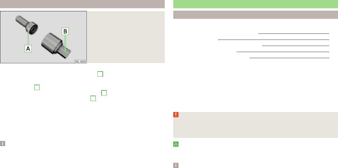
Anti-theft wheel bolts160
Antilock Braking System109
Armrest
Front72
Rear72
artificial leather133
Ashtray76
ASR
warning light37
Assembling the
bar ball, Step 1118
bar ball, Step 2118
Assist system
ABS109
Assist systems109
ABS37
ASR37
Cruise Control System111
EDL110
ESC37, 109
HBA110
HHC110
Parking aid110
START-STOP112
TCS109
Audio
see radio / navigation system4
Auto Check Control33
Automatic driving lamp control60
Automatic gearbox104
Manual shifting of gears106
Selector lever-emergency unlocking167
Selector lever lock105
Starting-off and driving106
Tiptronic106
Using the selector lever105
Automatic gearbox modes105
Automatic load deactivation147
automatic transmission
selector lever lock defect106
Automatic transmission
Kickdown106
Selector lever lock105
AUX97
B
Ball head
Check fitting119
Ready position117
Battery
In the remote control key166
Belts12
Belt tensioners15
Bonnet
Closing138
Opening138
Boot
Cargo element
83
Class N1 vehicles84
Double-sided floor covering84
Hooks82
See Boot lid55
Storage compartments83
Boot cover
Parking position83
Boot lid
automatic locking55
Closing55
Opening55
185
Index
Brake
information messages35
warning light35
Brake booster103
brake fluid
specification144
Brake fluid143
Checking144
information messages35
brake pedal (automatic gearbox)
indicator light41
brakes
Driving in107
Brakes
Brake booster103
Brake fluid144
Braking and stabilisation systems109
Handbrake103
Brakes and parking102
Braking
Information on braking102
Buttons in the door
Power windows55
C
Car care
Jack131
Car computer
See multifunction display
43
Care and maintenance124
Cargo element83
Car park ticket holder74
Carrier
Roof rack84
Cavity protection131
Central locking49
Problems53
Central locking button52
Change
Engine oil140
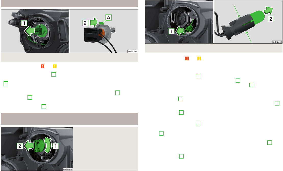
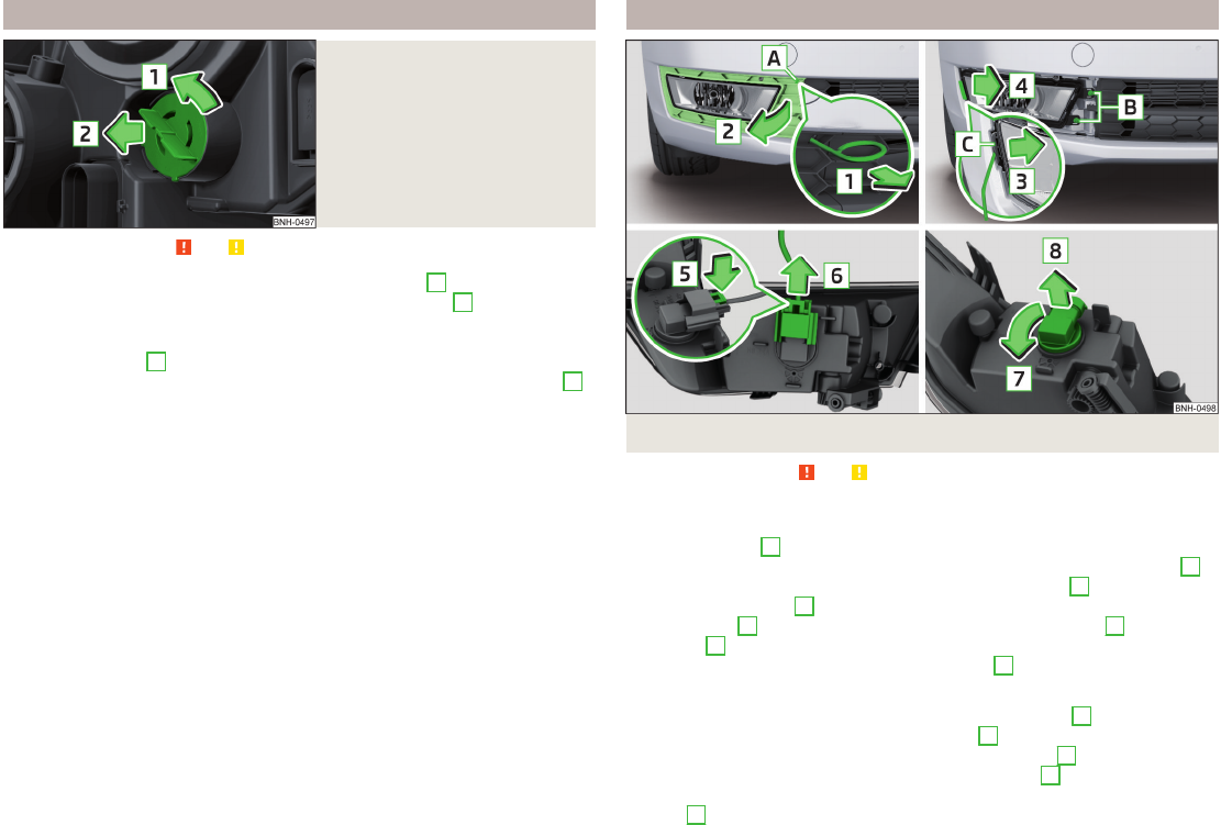
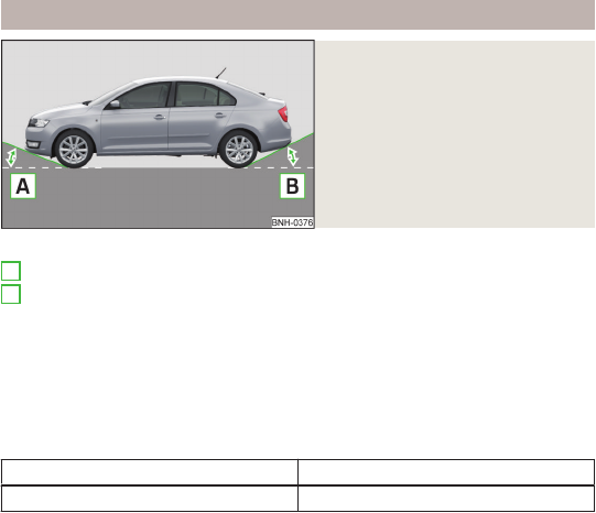
light bulb in tail light175
Changing
bulbs172
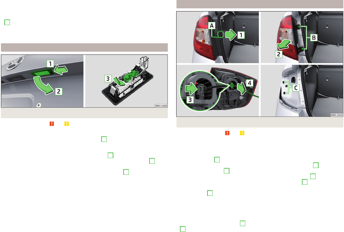
Front turn signal bulb174
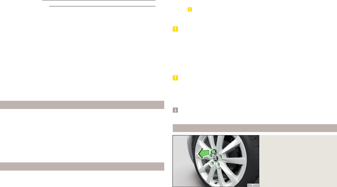
Wheels156
Changing a wheel
Follow-up work158
Preliminary work157
Remove and attaching a wheel158
Charging a vehicle battery146
Check
Fit ball head properly119
Checking
Battery electrolyte level146
Brake fluid144
Coolant143
Engine oil141
Oil level141
Windscreen washer fluid139
Checks
Statutory checks124
Children and safety22
Child safety
Side airbag24
Child safety lock53
Child seat
Classification24
ISOFIX25
on the front passenger seat23
TOP TETHER26
Use of child seats24
Use of ISOFIX child seats25
Chrome parts
see vehicle care129
Cigarette lighter75
cleaning
chrome parts129
Cleaning
Alcantara133
and maintaining belts134
artificial leather133
headlight glasses130
materials133
natural leather132
plastic parts129
seats covers of the electrically heated seats134
wheels131
Cleaning safety
belt134
Cleaning seat
covers134
Cleaning the interior
artificial leather133
Seat covers134
Cleaning the outside of the vehicle
Decorative films130
Cleaning the vehicle exterior
Cavity protection131
Door locking cylinder131
Headlight glasses130
Towing device131
Under-body protection131
wheels131
Windows and external mirrors130
Cleaning vehicle127
Cleaning vehicle exterior128
Plastic parts129
Rubber seals129
Vehicle paint work129
Wiper blades132
Clean interior
Safety belt134
clean outside of vehicle
chrome parts129
Climatronic
air distribution control87
Operating elements88
186
Index
Clothes hook79
Cockpit
12-Volt power outlet76
Ashtray76
Cigarette lighter75
General view29
Lights63
storage compartments73
useful equipment73
COMING HOME62
compartments73
Components of the puncture repair kits161
Computer
See multifunction display43
convenience turn signal60
Coolant142
Checking143
Indicator light36
Information messages36
Replenishing143
Temperature gauge32
Cooling system
cost-effective use89
malfunctions89
CORNER
See Fog lights with CORNER function61
Correct seated position9
Driver9
Front passenger10
Instructions11
Rear seats11
Counter for distance driven33
cruise control
operation111
operation Description112
Cruise control system
Warning light41
Cruise Control System111
Cup holders74
D
DAY LIGHT
See Daytime running lights59
Daytime running lights59
De-icing
windows130
Deactivating an airbag
20
Decorative films130
Defrosting rear window64
Delayed locking of the boot lid
see boot lid55
Departure angle180
Diesel
refer to Fuel136
Diesel fuel
Operation in winter136
Diesel particulate filter
Information messages38
Warning light38
Digital Clock
Time33
Dipstick141
Disconnecting and reconnecting
vehicle battery147
Display31
Compass points47
Coolant temperature
32
Fuel supply32
Gear changes43
Service intervals47
Display a low temperature42
Display of the second speed33
Disposal
Acceptance and recycling of used vehicles127
Distance driven33
Door
Child safety lock53
Closing51
Emergency locking167
Opening51
Warning light door open36
Door open
Warning light36
Double-sided floor covering84
Driving
Driving through water107
Emissions178
Fuel consumption178
Maximum speed181
off of made-up roads107
Driving in
Brake linings107
engine107
Tyres107
Driving off of made-up roads107
Driving through water107
E
Economical driving
Tips107
EDL110
Electrical power windows
Button in the passenger door56
Buttons in the driver's door56
Electronic Differential Lock (EDL)110
Electronic immobilizer
100
Electronic Stability Control (ESC)109
Emergency
Changing a wheel156
Hazard warning light system62
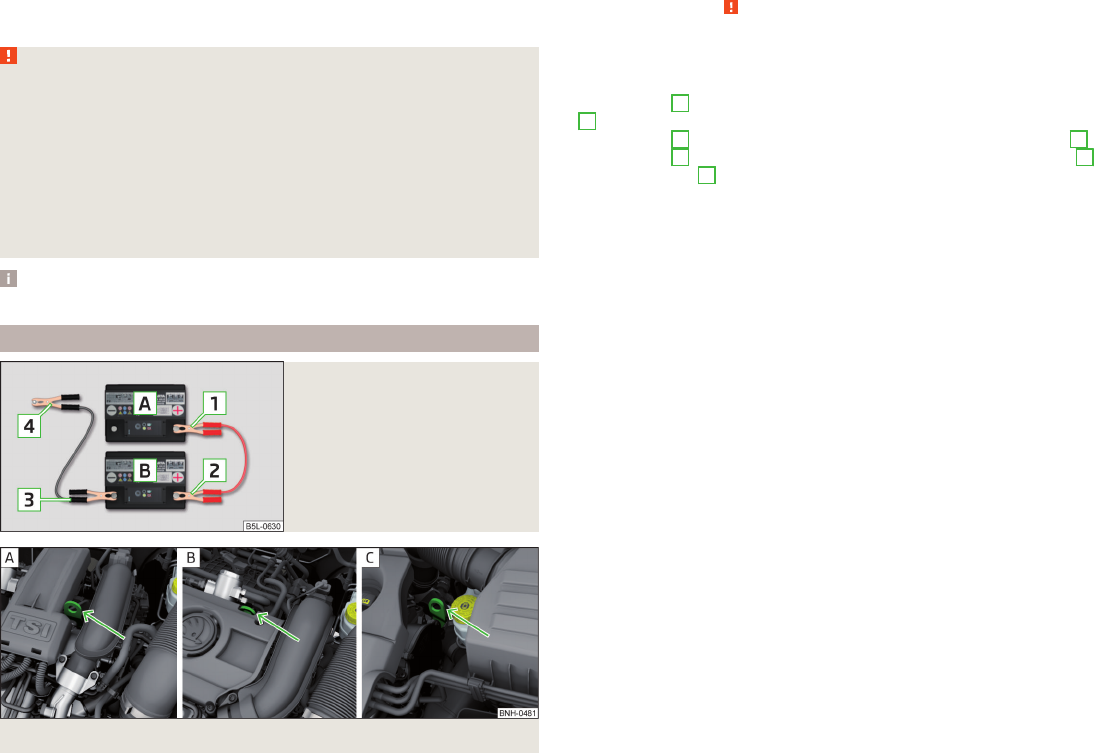
Jump-starting162, 163
Locking the door without a locking cylinder167
Selector lever-unlocking167
Towing the using the tow hitch165
Towing the vehicle164
tyre repair160
Unlocking the tailgate167
187
Index
Emergency equipment
Fire extinguisher154
First-aid kit 154
Jack155
Reflective Vest154
Vehicle tool kit155
Warning triangle154
emergency wheel155
Emissions178
Engine
Switching off the engine101
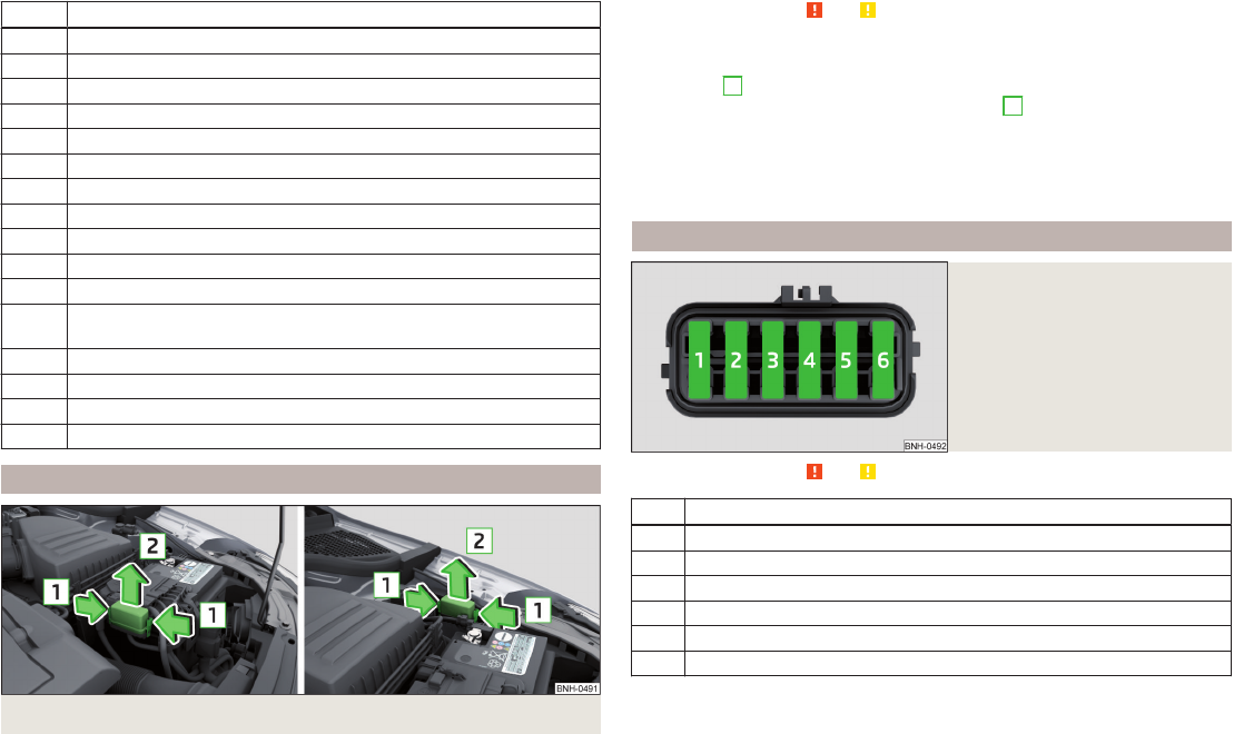
Engine compartment137
Brake fluid144
Overview139
Vehicle battery144
Engine number177
engine oil
information messages36
specification140
Engine oil140
change140
Checking141
Replenishing142
warning light36
EPC
Warning light38
ESC
Function109
Warning light37
Exhaust inspection system
Warning light38
F
Fastening elements81
Films130
Fire extinguisher154
First-aid kit 154
Flashing60
Fog lights61
Warning light40
Fog lights with CORNER function61
Footmats104
see footmats104
Force limit
Power windows56
Front airbag17
fuel
lead-free petrol135
Fuel134
Diesel136
Fuel gauge32
refer to Fuel134
Refuelling135
Fuel consumption178
Fuel reserve
Warning light39
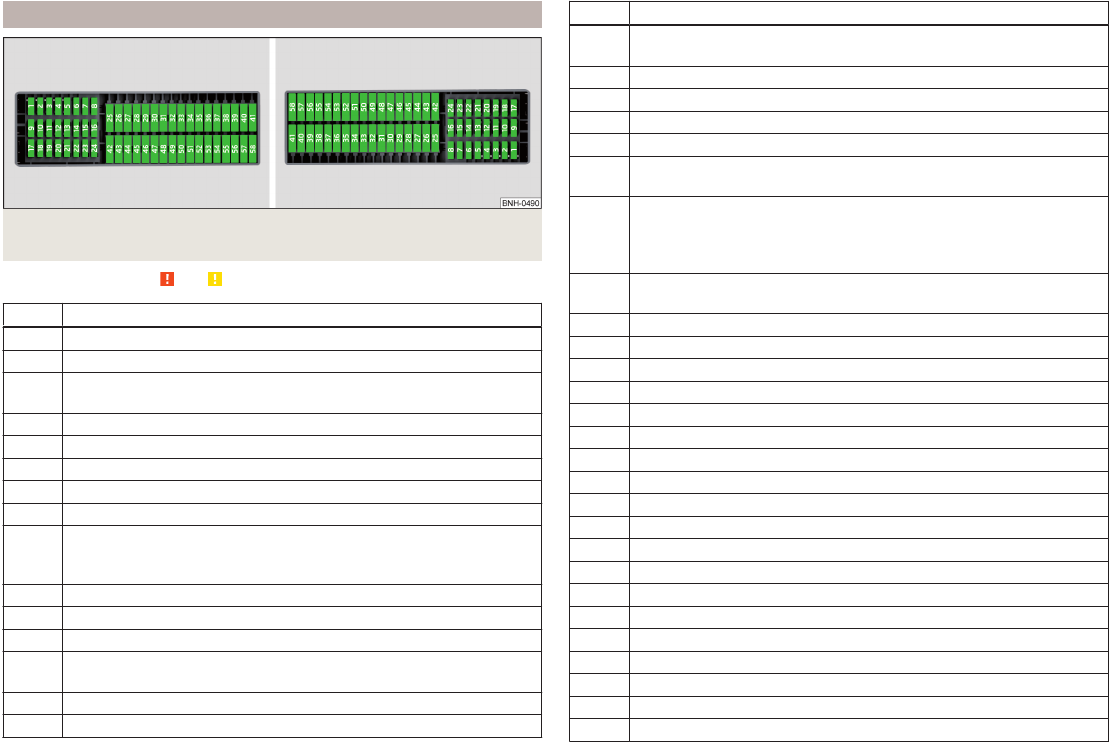
Fuses
Assignment169
Assignment of fuses in the dash panel170
Colour coding169
Fuse assignment in the engine compartment171
Replacing169
Fuses in the engine compartment
Assignment171
G
Gearbox
Warning messages
33
Gear change
Gear recommendation43
Information on the selected gear43
Gear changing
Gear stick104
gears
spare156
General view
Cockpit29
Generator
Indicator light35
Genuine parts125
Glasses compartment78
Glow plug system
Warning light38
GSM90
H
Handbrake103
Warning light35
Hazard warning light system62
HBA110
Head airbag19
Headlight cleaning system
Headlight cleaning system66
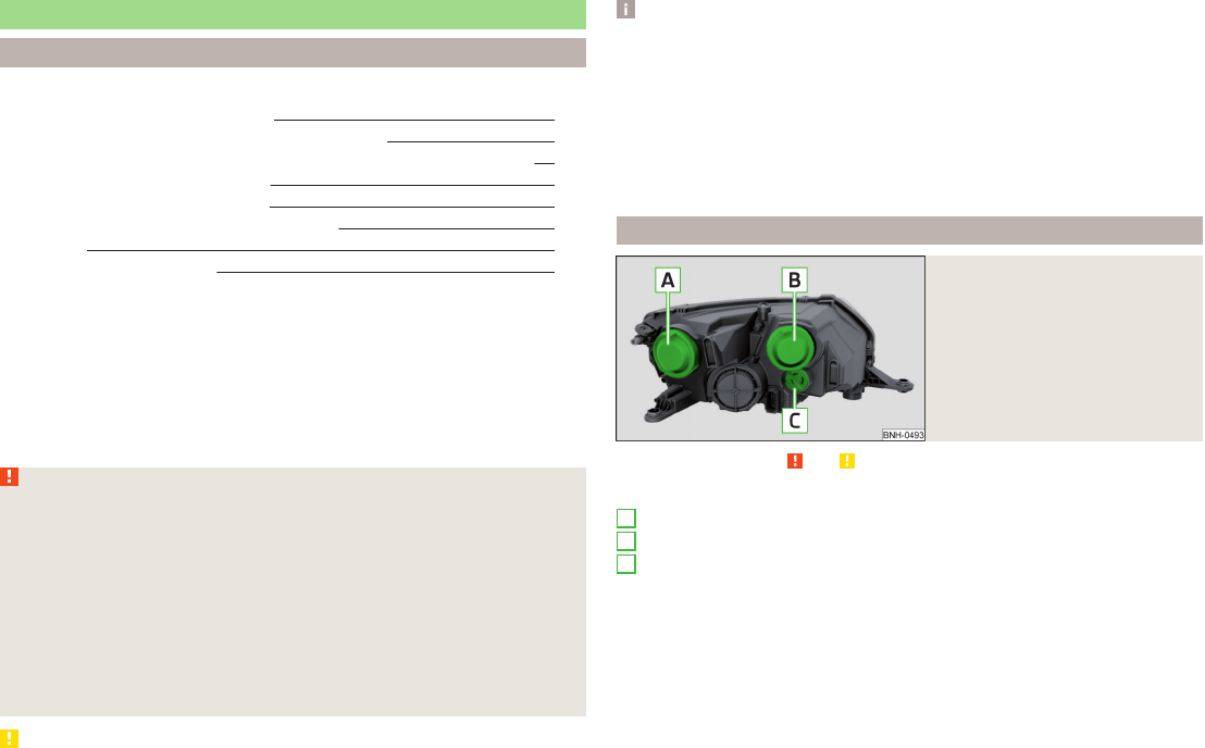
Headlights
Bulb arrangement172
Driving abroad63
Headlight cleaning system66
Head restraints70
Adjust height70
Headrest,
removing and installing70
Heating85
Air distribution control87
Control elements87
Exterior mirror
68
Rear window64
Seats71
Heating rear window64
HHC110
Hill Hold Control (HHC)110
Hitch116
Accessories120
Drawback load116
Hooks82
Horn29
Hydraulic Brake Assist (HBA)110
188
Index
I
Ice scrapers130
Ignition101
Ignition lock101
Immobilizer100
Indicator lights34
Individual settings
Locking
52
Unlocking52
Inertia reels15
Information system41
Compass point display47
Display a low temperature42
Door warning43
Gear recommendation43
MAXI DOT display46
Multifunction display43
Operation42
Service interval display47
instrument cluster
Auto Check Control33
Instrument cluster30
Counter for distance driven33
Display31
Display of the second speed33
Fuel gauge32
Indicator lights
34
Overview30
Revolution counter31
see instrument cluster30
Speedometer31
Temperature gauge32
Interior care132
Natural leather132
interior light
Front63
Interior monitor54
ISOFIX25
J
Jack155
Maintenance131
Jacking points
Raise vehicle159
Jump-starting162, 163
K
Key
Lock50
Start engine101
Unlock50
L
lamp failure
warning lamp38
lamps
warning lamp38
Leather
Natural leather care132
LEAVING HOME62
Lever
Main beam60
Turn signal60
Windscreen wipers66
lever lock selection (automatic gearbox)
indicator light41
Light
COMING HOME / LEAVING HOME62
Daytime running lights59
Fog lights with CORNER function61
Parking light63
Lighting
Luggage compartment80
Lights58
Automatic driving lamp control60
Beam range adjustment58
Cockpit63
Fog lights61
Hazard warning light system62
Headlight flasher60
Indicator lights34
Low beam58
Main beam60
Parking light58
Rear fog light61
Replacing bulbs172
switching on/off58
Turn signal60
Lock
Key50
Lock/unlock steering lock101
Locking
Individual settings52
Remote control50
Locking and unlocking the vehicle from the in-
side52
Locking the door without a locking cylinder
Emergency167
Low beam58
Low tyre pressure warning
refer to the tyre pressure monitoring115
Luggage compartment80
Cover82
Emergency unlocking167
Fastening elements81
Fixing nets81
Lighting80
Unlocking the tailgate167
Luggage compartment cover82
Luggage compartment lid54
M
Main beam60
Warning light41
Maintenance
see vehicle care129
189
Index
Manual air conditioning
Air distribution control87
Operating elements88
Manual gear changing
see gear changing104
MAXI DOT
See MAXI DOT display46
MAXI DOT display46
Main menu46
Operation42
Settings47
Maximum
permissible weights177
Maximum speed181
MDI97
Mechanical windows57
open and close57
Media
see radio / navigation system4
MFD
See multifunction display43
Mirror
Exterior mirror68
Make-up65
Mobile phone90
Connecting to the hands-free system93
Modifications124
Modifications and technical alterations
Airbags126
Service125
Spoiler126
Multifunction display
Functions43
Information45
Memory44
Operation42
Multimedia96
Multimedia holder77
N
N184
Nameplate177
Navigation system4
Nets81
Notes for driving with tyre repaired162
Notes on using wheels
148
O
oil
information messages36
Oil
See Engine oil141
oil pressure
information messages36
On-board computer
See multifunction display43
Operating weight178
Operation in winter
Diesel fuel136
Vehicle battery146
Original accessories125
Outside temperature45
Overview
Engine compartment139
Indicator lights34
P
Parking
103
Parking aid110
Parking aid110
Function111
Parking light58
Parking space103
Parking vehicle
Parking103
Part replacement124
Passive safety
Before setting off8
Driving safety8
Safety equipment8
Passive Safety8
Payload178
Pedals104
Footmats104
Petrol
see fuel135
Plastic parts129
Pockets on the front seat rests80
Polishing vehicle paint work
see vehicle care129
Power outlet
12 V76
Power steering
Warning light37
Power windows55
Practical equipment
12-Volt power outlet76
Net pockets on the front seat rests80
Reflective Vest154
Practical features
Storage pockets on the front seats79
Waste container77
Puncture set160
R
Radiator fan139
Radio4
Raise vehicle159
Rear
interior light64
Rear fog light61
Warning light38
Rear mirror66
Exterior mirror68
Interior mirror67
190
Index
Refuelling135
Fuel135
Remote control
Locking50
Replacing the battery166
Synchronisation process166
Unlocking50
Remote control key
Replacing the battery166
Removing the
bar ball, Step 1119
bar ball, Step 2119
Repairs and technical alterations124
Replacing
Bulb for main beam, daytime running lights and
parking light173
Bulb for the fog light174
Bulb for the licence plate light175
Bulb in rear light176
Fuses169
Fuses in the dash panel169
Fuses in the engine compartment171
High beam bulb (halogen headlights)173
Rear window wiper blade168
Vehicle battery147
windscreen wiper blades168
Replenishing
Coolant143
Engine oil142
Windscreen washer fluid139
Retraction and economical driving107
Revolution counter31
Roof
Load85
Roof rack84
mounting points85
Roof load85
Rubber seals129
S
SAFE
See Safe securing system51
SAFELOCK
See Safe securing system51
Safe securing system51
Safety
8
Child safety22
Child safety seats22
Correct seated position9
Head restraints70
ISOFIX25
TOP TETHER26
Save electrical energy107
Save fuel107
Seals
Vehicle care129
Seat
Adjusting69
Seat belt
warning light35
Seat belts12
Belt tensioners15
fastening and unfastening14
Height adjustment15
Inertia reels15
The physical principle of a frontal collision
13
Seat features71
Seats
Front armrest72
Head restraints70
Heating71
Rear armrest72
Seat backrests72
Seats and head restraint69
Selector lever
Refer to Selector lever105
Service125
Service interval display47
Setting33
seats and head restraints69
Setting the33
Side airbag18
SmartGate
connection98
Password99
Settings99
Smart Gate
Website99
Snow chains153
Spare
change156
spare wheel155
change156
instructions156
Speedometer31
See speedometer31
Speed symbol
See Wheels151
Spoiler126
Staring engine
Jump-starting163
START-STOP112
Jump-starting163
Manually deactivating/activating the system114
Operating conditions of the system113
operation in vehicles with automatic gearbox113
operation in vehicles with manual gearbox113
system-related automatic start-up114
Start engine101
Starting engine
Jump-starting162
START STOP
Information messages114
Stating and turning off the engine100
Steering wheel10
Stopping103
Storage73
191
Index
Storage compartment
Glasses compartment78
in the boot83
in the centre console74
in the front arm rest78
on the front passenger side78
Storage compartments73
Storage pockets on the front seats79
Stowage
compartments in the doors74
Sun visors65
Switching off the engine101
Switch light on/off58
Switch off ignition101
Switch on ignition101
T
Taking care of your vehicle
Automatic car wash system128
High-pressure cleaner128
Washing by hand127
Wash system128
TCS
Operation109
Technical data177
Telephone90
Tiptronic106
Tools
155
TOP TETHER26
Towing164
Towing a trailer122
Towing device
Description116
Operation and maintenance131
Towing eye
Front165
Rear165
Towing protection54
Traction Control System (TCS)109
Trailer121
13-pin socket121
connection and disconnection121
Loading122
Safety eye121
Towing a trailer122
Trailer operation116
Transport
Luggage compartment80
Roof rack84
Transporting73
Transporting children safely22
Triangle154
Turn signal60
Turn signal system
Warning light40
two-way radio systems90
Tyre
Damage150
Explanation of the labelling151
see wheels151
Tyre inflation pressure
Warning light40
Tyre load-bearing capacity
See Wheels151
Tyre pressure149
Tyre pressure monitoring115
Save tyre pressure values115
Tyre repair
General notes161
Preparations161
Pressure test162
Sealing and inflating the tyre162
Tyres148
new107
Tyre pressure149
Wear and tear149
Wear indicators150
Tyre size151
see wheels151
U
Under-body
Vehicle care131
Under-body protection131
Unlock
Key50
Unlocking
Individual settings
52
Remote control50
Unlocking and locking49
USB97
Used vehicles
Acceptance and recycling127
Useful equipment
Ashtray76
Car park ticket holder74
Cigarette lighter75
Clothes hook79
Cup holders74
Glasses compartment78
Multimedia holder77
Storage compartment73
Using the information system42
Using the selector lever105
V
Vehicle battery
Automatic load deactivation
147
charging146
Checking the battery electrolyte level146
Cover145
Operation in winter146
Replacing147
Safety instructions144
vehicle care
chrome parts129
Vehicle care
Alcantara133
Artificial leather133
192
Index
Cavity protection131
Cleaning vehicle exterior128
Cleaning wheels131
Decorative films130
Door locking cylinder131
Headlight glasses130
Interior care132
Maintenance129
Materials133
Natural leather132
Plastic parts129
Polishing vehicle paint work129
Rubber seals129
Safety belt134
Seat covers134
Under-body protections131
washing127
Vehicle Condition
see Auto Check Control33
Vehicle data sticker177
Vehicle data sticker and nameplate
Vehicle data sticker and nameplate177
Vehicle dimensions179
Vehicle height179
Vehicle Identification Number (VIN)177
Vehicle length179
Vehicle tool kit155
Vehicle width179
Vest
Placement of the reflective vest154
VIN
Vehicle Identification Number177
Visibility64
Visors
See front sun visors65
W
Warning at excessive speeds46
Warning triangle154
Washing
Automatic car wash system128
by hand127
High-pressure cleaner128
Washing vehicles127
Waste container77
Water
Driving through107
Weather conditions124
Wheel bolts
Anti-theft wheel bolts160
Caps157
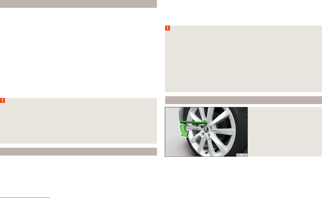
Loosening and tightening158
Wheel rims148
wheels
spare wheel156
Wheels
Age of wheels148
Changing156
Driving style149
Full trim157
General information148
Load index151
Snow chains153
Speed symbol151
Storage of wheels148
Tyre damage150
Tyre pressure149
Tyre size151
Tyre wear149
Tyre wear indicator150
Unidirectional tyres151
Wheel balance149
Wheels exchange150
Winter tyres153
Wi-Fi
Password98, 99
Settings99
Website99
Window
Interior mirror67
Window wiper
Replacing the rear window wiper blade168
Windscreen washer fluid
Checking139
Replenishing139
Warning light40
Winter139
Windscreen washer system139
Windscreen wipers66
Windscreen wipers
Activating66
Replacing the windscreen wipers168
Windscreen washer fluid139
Windscreen wipers and washers65
Winter operation152
De-icing windows130
Snow chains153
Winter tyres153
Winter tyres
See Wheels153
Wiper blades132
Service position of the windscreen wiper arms168
Wipers
Maintaining wiper blades132
193
Index
194
Index
Reprinting, reproduction, translation, or any other use, either in whole or in
part, is not permitted without the written consent of ŠKODA AUTO a.s..
ŠKODA AUTO a.s. expressly reserves all rights relating to copyright laws.
Gebruikershandleiding.com neemt misbruik van zijn services uitermate serieus. U kunt hieronder aangeven waarom deze vraag ongepast is. Wij controleren de vraag en zonodig wordt deze verwijderd.
Product:
Spelregels forum
Om tot zinvolle vragen te komen hanteren wij de volgende spelregels:
lees eerst de handleiding door;
controleer of uw vraag al eerder door iemand anders is gesteld;
probeer uw vraag zo duidelijk mogelijk te stellen;
heeft u een probleem en al geprobeerd om dit op te lossen, vermeld dit erbij aub;
heeft u een oplossing gekregen van een bezoeker dan horen wij dat graag in dit forum;
wilt u een reactie geven op een vraag of antwoord, gebruik dan niet dit formulier maar klik op de knop 'reageer op deze vraag';
uw vraag wordt direct op de website gezet; vermijd daarom persoonlijke gegevens in te vullen;
Belangrijk! Als er een antwoord wordt gegeven op uw vraag, dan is het voor de gever van het antwoord nuttig om te weten als u er wel (of niet) mee geholpen bent! Wij vragen u dus ook te reageren op een antwoord.
Belangrijk! Antwoorden worden ook per e-mail naar abonnees gestuurd. Laat uw emailadres achter op deze site, zodat u op de hoogte blijft. U krijgt dan ook andere vragen en antwoorden te zien.
Abonneren
Abonneer u voor het ontvangen van emails voor uw Skoda Rapid - 2015 bij:
nieuwe vragen en antwoorden
nieuwe handleidingen
U ontvangt een email met instructies om u voor één of beide opties in te schrijven.
Ontvang uw handleiding per email
Vul uw emailadres in en ontvang de handleiding van Skoda Rapid - 2015 in de taal/talen: Engels als bijlage per email.
De handleiding is 26,81 mb groot.
U ontvangt de handleiding per email binnen enkele minuten. Als u geen email heeft ontvangen, dan heeft u waarschijnlijk een verkeerd emailadres ingevuld of is uw mailbox te vol. Daarnaast kan het zijn dat uw internetprovider een maximum heeft aan de grootte per email. Omdat hier een handleiding wordt meegestuurd, kan het voorkomen dat de email groter is dan toegestaan bij uw provider.
Uw handleiding is per email verstuurd. Controleer uw email
Als u niet binnen een kwartier uw email met handleiding ontvangen heeft, kan het zijn dat u een verkeerd emailadres heeft ingevuld of dat uw emailprovider een maximum grootte per email heeft ingesteld die kleiner is dan de grootte van de handleiding.
Er is een email naar u verstuurd om uw inschrijving definitief te maken.
Controleer uw email en volg de aanwijzingen op om uw inschrijving definitief te maken
U heeft geen emailadres opgegeven
Als u de handleiding per email wilt ontvangen, vul dan een geldig emailadres in.
Uw vraag is op deze pagina toegevoegd
Wilt u een email ontvangen bij een antwoord en/of nieuwe vragen? Vul dan hier uw emailadres in.