


-
Hoe kom ik het beste bij de claxson van mijn Fabia lll 2018 ? Gesteld op 18-6-2024 om 19:13
Reageer op deze vraag Misbruik melden -
Ik heb een Skoda Fabia van 2006,2e hands gekocht maar heb me nooit verdiept in hoe je dingen moet instellen.Er was geen boekje bij.
Reageer op deze vraag Misbruik melden
Zou iemand mij in of in de buurt van Venray mij dat willen leren.
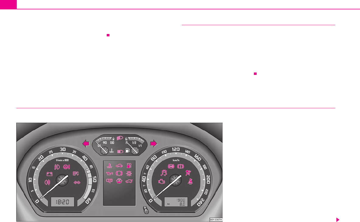
Nu zou ik vooral kmstand en klok instellen willen weten? Gesteld op 29-3-2024 om 02:28 -
waar zit de controle voor de olie in de versnellingsbak Gesteld op 27-3-2024 om 13:41
Reageer op deze vraag Misbruik melden -
Waar bevindt zich de stekker van de parkeersensoren zich achteraan bij een Skoda fabia combi? Gesteld op 26-3-2023 om 11:16
Reageer op deze vraag Misbruik melden -
Display van Skoda Fabia (2007) is zwart scherm, Nergens in het boekje hoe je het probleem kunt oplossen .
Reageer op deze vraag Misbruik melden
Kan het een zekering zijn die kapot is? Gesteld op 20-8-2022 om 15:45 -
Mijn chauffauche blaast niet meer wat kan het zijn ? Gesteld op 20-5-2022 om 14:19
Reageer op deze vraag Misbruik melden
-
ik heb een skoda fabia model 2019 gereden km 55000
Reageer op deze vraag Misbruik melden
links achterwiel hoor je een dat lijkt op een versleten lager hoe harden ik rijd hoe harden het geluid
kan dat met een die km stand Gesteld op 15-5-2022 om 19:29 -
Hoe haal ik het kinderslot van de achterdeur er af
Reageer op deze vraag Misbruik melden
Gesteld op 29-4-2022 om 08:18 -
hoe kan ik het piepje horen wanner ik de gewenste snelheid heb berijkt Gesteld op 8-4-2022 om 13:01
Reageer op deze vraag Misbruik melden -
Wat is het type van de batterij in de sleutel van mijn Skoda Fabia, bouwjaar 2020 Gesteld op 4-4-2022 om 14:26
Reageer op deze vraag Misbruik melden -
Welke batterij gaat in de sleutel voor de fabia combi uit 2019 Gesteld op 1-4-2022 om 13:59
Reageer op deze vraag Misbruik melden -
Waar zit de zekering voor de remlichten Skoda fabia 2001 er staan allerlei nummers en je onder dashboard en motorkap Gesteld op 27-12-2021 om 12:02
Reageer op deze vraag Misbruik melden
-
Hoe stel ik Nederlands in blijft in Duits of keuzes andere taken behalve nederlands Gesteld op 3-10-2021 om 15:54
Reageer op deze vraag Misbruik melden -
hoe kan ik de banden spanning opslaan(skoda fabia combi) Gesteld op 1-8-2021 om 17:41
Reageer op deze vraag Misbruik melden -
Spiraallampje blijf flikkeren tijdens rijden
Reageer op deze vraag Misbruik melden
Motor is op klachten digitaal gecheckt klacht niet te vinden
Vanmorgen bij koude start weer een lampje nu de roetfilter
Hoe kan het dat bij uitlezen dit niet naar voren kwam ? Gesteld op 19-7-2021 om 14:21-
Egr klep aan vervanging toe, vaak garantie naar sjoemelupdate! Geantwoord op 8-11-2021 om 19:06
Waardeer dit antwoord Misbruik melden
-
-
Ik heb een skoda fabia turbo diesel Zit er distributieriem of ketting op? Na hoeveel km moet het vervangen worden ? Gesteld op 25-6-2021 om 12:14
Reageer op deze vraag Misbruik melden-
Kijk in instructieboekje, na ong. 210.000km. Geantwoord op 8-11-2021 om 19:08
Waardeer dit antwoord Misbruik melden
-
-
Mijn lichtje van de koelvloeistof licht op bij starten maar gaat direkt erna weer uit!! Gesteld op 21-5-2021 om 09:44
Reageer op deze vraag Misbruik melden -
Hoe kan ik de digitale snelheidsmeter activeren in km eenheid? Instructie in handleiding zegt hier niets over. Gesteld op 18-4-2021 om 11:21
Reageer op deze vraag Misbruik melden
-
Hoe kan ik mijn klokje goed zetten in mijn skoda fabia van 2002 ik hoor het graag Gesteld op 28-3-2021 om 19:13
Reageer op deze vraag Misbruik melden-
rood stiftje waarmee je de dagteller op nul zet in het venster van de km teller , een weinig naar links draaien voor de uren en naar rechts voor de minuten
Waardeer dit antwoord Misbruik melden
Geantwoord op 28-3-2021 om 22:12
-
-
Menu zegt dat ik linkerachterlicht moet nakijken, maar werkt gewoon Gesteld op 26-11-2020 om 10:03
Reageer op deze vraag Misbruik melden -
De deur wil niet open met de contact sleutel de sleutel geeft een rood lichtje Gesteld op 22-3-2020 om 11:16
Reageer op deze vraag Misbruik melden -
Waar zit de hendel om de tankdop van Skoda Fabia te openen Gesteld op 27-1-2020 om 09:30
Reageer op deze vraag Misbruik melden-
De fabia heeft geen handle gewoon het klepje met de hand opendoen. Geantwoord op 28-5-2020 om 00:36
Waardeer dit antwoord (7) Misbruik melden
-
-
Hoe kan ik mijn auto openen zonder afstands bediening omdat de accu losgekoppeld is
Reageer op deze vraag Misbruik melden
Skoda fabia Gesteld op 6-10-2019 om 11:06-
Ik doe mijn auto met de sleutel in het linker portier open. Geantwoord op 12-10-2019 om 17:04
Waardeer dit antwoord Misbruik melden
-
-
LS,
Reageer op deze vraag Misbruik melden
Ik heb mijn Skoda Fabia Combi Greenline tweedehands gekocht in juli 2018. Km stand is op dit moment 160.000. Ik weet niet wanneer de distributieriem vervangen moet worden (of is er sprake van een distributieketting, dan hoeft het niet geloof ik?) Ik vind hierover ook niets in het onderhoudsboekje. Ik kijk uit naar uw antwoord. ML Bal Gesteld op 23-9-2019 om 12:50-
Het is een riem en dient voor 210000 vervangen te worden samen met waterpomp. Geantwoord op 6-1-2020 om 22:38
Waardeer dit antwoord (1) Misbruik melden
-
-
Er zit een ketting op, wij hebben een fabia combi 1.2 tsi van 2013 Geantwoord op 24-6-2021 om 12:36
Waardeer dit antwoord Misbruik melden -
waar zit de schakelaar vn de spiegel verwrming
Reageer op deze vraag Misbruik melden
Skoda Fabia Gesteld op 7-2-2019 om 09:22-
De knop.vokr het verstellen van de buitenspiegels kan een slag naar voren worden doorgedraaid. Dit is de ontdooi stand voor de buitenspiegels Geantwoord op 4-12-2019 om 09:58
Waardeer dit antwoord Misbruik melden
-
-
hoe deuren van binnenin vergrendelen bij skoda fabia Gesteld op 13-9-2018 om 18:27
Reageer op deze vraag Misbruik melden-
knopje aan vitessepook Geantwoord op 12-12-2019 om 12:18
Waardeer dit antwoord Misbruik melden
-
-
Goedemorgen. Het blauwe tempratuurmeter brand bij hets starten van de auto. Deze verdwijnt weer tijdens het rijden na ongeveer 15 min. Ik heb de handleiding doorgenomen maar ik kom er niet uit. Wellicht kan iemand mij helpen. Alvast bedankt. Gesteld op 23-6-2018 om 08:44
Reageer op deze vraag Misbruik melden-
Hallo,in het expansie reservoir zit een voelertje als jij het koelvloeistof te lang niet verwisseld kan er drab ontstaan dat op het voelertje zit als deze vloeistof warm wordt dan verdwijnt deze of lost zich op dan werkt het voelertje weer.Dus dit KAN het probleem zijn. Geantwoord op 23-6-2018 om 10:29
Waardeer dit antwoord (5) Misbruik melden
-
-
heb ik ook!!!! gaat uit als motor op temperatuur is staat in instructie boekje Geantwoord op 15-10-2018 om 18:22
Waardeer dit antwoord Misbruik melden -
zolang het blauwe lampje brand is uw motor nog niet op temperatuur Geantwoord op 9-4-2020 om 18:49
Waardeer dit antwoord Misbruik melden -
Zaterdag werg ik aangehouden door een agent en wees mij erop
Reageer op deze vraag Misbruik melden
dat een of meer achterlichten kapot waren. Omdat ik niet snel genoeg
was om het probleem te verhelpen moest hij mij een bekeuring uit
schrijven. Het probleem was dat ik niet de lamp en de daarbij behorende
zekering niet kon vinden omdat er op de zekeringenkast geen nummer
staat van het nummer dat bij de gebruiker van de lamp en de zekering.
Derhalve moest ik hiervoor naar de garage en kon het probleem niet
ter plekke op lossen. Jammer.
Har Sleutels, 6075 Gt Herkenbosch nr. 13
mailadres:sleuton@gmail.com
Mijn fabia is van 2002 Gesteld op 29-4-2018 om 10:34-
Ik heb een handleiding van 2004. Wellicht kun je hier wat mee. stuur mij een mail rhe [add] hetnet.nl en ik stuur je de handleiding. Overigens gratis hoor! Geantwoord op 2-5-2018 om 11:41
Waardeer dit antwoord (3) Misbruik melden
-
-
mijn stuur bekrachting is uit gevallen waar zit hij van een skoda fabia uit 2002
Reageer op deze vraag Misbruik melden
Men zegt dat je hem kan vullen maar waar zit hij onder de motorkap Gesteld op 25-3-2018 om 13:16-
ja ook mijn stuur bekrachting is uit gevallen waar zit hij van een skoda fabia uit 2007
Waardeer dit antwoord (3) Misbruik melden
wat is de oplossing
grst Theo Geantwoord op 10-11-2018 om 14:30
-
-
Wanneer moet ik de distributie riem van mijn skoda Fabia 1.2tdi greenline combi 2012 vervangen Gesteld op 24-8-2017 om 19:15
Reageer op deze vraag Misbruik melden-
150000 km of 48 maanden Geantwoord op 27-10-2017 om 00:33
Waardeer dit antwoord (3) Misbruik melden
-
-
210.000km. Er staat geen tijdslimiet voor. Geantwoord op 17-3-2018 om 16:07
Waardeer dit antwoord (4) Misbruik melden -
ruitenwissers doen het niet meer waar zitten de zekeringen van de ruitenwisser?
Reageer op deze vraag Misbruik melden
Gesteld op 26-3-2016 om 20:11-
Bestuurderszijde aan de zijkant van dashboard. Geantwoord op 28-3-2016 om 11:00
Waardeer dit antwoord (4) Misbruik melden
-
-
wat is het rode knipperlichtje dat gaat als de auto uit staat Gesteld op 14-3-2016 om 09:47
Reageer op deze vraag Misbruik melden-
hoe kan ik een vraagbaak bestelen Geantwoord op 11-6-2016 om 13:52
Waardeer dit antwoord (6) Misbruik melden
-
-
zelf vervangen dynamo Skoda Fabia Fabia 1.4 16V 75pk Classic Gesteld op 21-8-2015 om 13:24
Reageer op deze vraag Misbruik melden-
hoe vervang ik zel de dynamo fabia 1.4 16v Geantwoord op 11-3-2017 om 11:06
Waardeer dit antwoord (13) Misbruik melden
-
