758350
10
Verklein
Vergroot
Pagina terug
1/16
Pagina verder
IMPORTANT:
Read Before Using
Operating/Safety Instructions
5280
-2-
Work area safety
Keep work area clean and well lit. Cluttered
or dark areas invite accidents.
Do not operate power tools in explosive
atmospheres, such as in the presence of
flammable liquids, gases or dust. Power
tools create sparks which may ignite the dust
or fumes.
Keep children and bystanders away while
operating a power tool. Distractions can
cause you to lose control.
Electrical safety
Power tool plugs must match the outlet.
Never modify the plug in any way. Do not
use any adapter plugs with earthed
(grounded) power tools. Unmodified plugs
and matching outlets will reduce risk of
electric shock.
Avoid body contact with earthed or grounded
surfaces such as pipes, radiators, ranges
and refrigerators. There is an increased risk
of electric shock if your body is earthed or
grounded.
Do not expose power tools to rain or wet
conditions. Water entering a power tool will
increase the risk of electric shock.
Do not abuse the cord. Never use the cord
for carrying, pulling or unplugging the power
tool. Keep cord away from heat, oil, sharp
edges or moving parts. Damaged or entangled
cords increase the risk of electric shock.
When operating a power tool outdoors,
use an extension cord suitable for outdoor
use. Use of a cord suitable for outdoor use
reduces the risk of electric shock.
If operating a power tool in a damp location
is unavoidable, use a Ground Fault Circuit
Interrupter (GFCI) protected supply. Use of
an GFCI reduces the risk of electric shock.
Personal safety
Stay alert, watch what you are doing and
use common sense when operating a
power tool. Do not use a power tool while
you are tired or under the influence of drugs,
alcohol or medication. A moment of inattention
while operating power tools may result in
serious personal injury.
Use personal protective equipment. Always
wear eye protection. Protective equipment
such as dust mask, non-skid safety shoes, hard
Read all safety warnings and all instructions. Failure to follow the warnings
and instructions may result in electric shock, fire and/or serious injury.
SAVE ALL WARNINGS AND INSTRUCTIONS FOR FUTURE REFERENCE
The term “power tool” in the warnings refers to your mains-operated (corded) power tool or
battery-operated (cordless) power tool.
General Power Tool Safety Warnings
Safety Symbols
The definitions below describe the level of severity for each signal word. Please read the manual
and pay attention to these symbols.
!
This is the safety alert symbol. It is used to alert you to potential
personal injury hazards. Obey all safety messages that follow this
symbol to avoid possible injury or death.
DANGER indicates a hazardous situation which, if not avoided, will
result in death or serious injury.
WARNING indicates a hazardous situation which, if not avoided, will
result in death or serious injury.
CAUTION, used with the safety alert symbol, indicates a hazardous
situation which, if not avoided, will result in minor or moderate injury.
hat, or hearing protection used for appropriate
conditions will reduce personal injuries.
Prevent unintentional starting. Ensure the
switch is in the off-position before
connecting to power source and / or battery
pack, picking up or carrying the tool.
Carrying power tools with your finger on the
switch or energizing power tools that have the
switch on invites accidents.
Remove any adjusting key or wrench before
turning the power tool on. A wrench or a
key left attached to a rotating part of the
power tool may result in personal injury.
Do not overreach. Keep proper footing and
balance at all times. This enables better
control of the power tool in unexpected
situations.
Dress properly. Do not wear loose clothing
or jewelry. Keep your hair, clothing and
gloves away from moving parts. Loose
clothes, jewelry or long hair can be caught in
moving parts.
If devices are provided for the connection
of dust extraction and collection facilities,
ensure these are connected and properly
used. Use of dust collection can reduce dust-
related hazards.
Power tool use and care
Do not force the power tool. Use the
correct power tool for your application. The
correct power tool will do the job better and
safer at the rate for which it was designed.
Do not use the power tool if the switch does
not turn it on and off. Any power tool that
cannot be controlled with the switch is
dangerous and must be repaired.
Disconnect the plug from the power source
and/or the battery pack from the power tool
before making any adjustments, changing
accessories, or storing power tools. Such
preventive safety measures reduce the risk of
starting the power tool accidentally.
Store idle power tools out of the reach of
children and do not allow persons
unfamiliar with the power tool or these
instructions to operate the power tool.
Power tools are dangerous in the hands of
untrained users.
Maintain power tools. Check for misalignment
or binding of moving parts, breakage of
parts and any other condition that may
affect the power tool’s operation. If damaged,
have the power tool repaired before use.
Many accidents are caused by poorly
maintained power tools.
Keep cutting tools sharp and clean. Properly
maintained cutting tools with sharp cutting
edges are less likely to bind and are easier to
control.
Use the power tool, accessories and tool
bits etc. in accordance with these instructions,
taking into account the working conditions
and the work to be performed. Use of the
power tool for operations different from those
intended could result in a hazardous situation.
Service
Have your power tool serviced by a qualified
repair person using only identical
replacement parts. This will ensure that the
safety of the power tool is maintained.
-3-
Safety Rules for Circular Saws
Read all safety warnings and all instructions.
Keep hands away from
cutting area and the blade.
Keep your second hand on auxiliary handle,
or motor housing. If both hands are holding
the saw, they cannot be cut by the blade.
Do not reach underneath the workpiece.
The guard cannot protect you from the blade
below the workpiece.
Adjust the cutting depth to the thickness of
the workpiece. Less than a full tooth of the
blade teeth should be visible below the
workpiece.
Never hold piece being cut in your hands or
across your leg. Secure the workpiece to a
stable platform. It is important to support the
work properly to minimize body exposure,
blade binding, or loss of control.
Hold the power tool by insulated gripping
surfaces only, when performing an
operation where the cutting tool may
contact hidden wiring or its own cord.
Contact with a "live" wire will also make
exposed metal parts of the power tool “live” and
could give the operator an electric shock.
When ripping, always use a rip fence or
straight edge guide. This improves the
accuracy of cut and reduces the chance of
blade binding.
Always use blades with correct size and
shape (diamond versus round) of arbor
holes. Blades that do not match the mounting
hardware of the saw will run eccentrically,
causing loss of control.
Never use damaged or incorrect blade
washers or bolt. The blade washers and bolt
were specially designed for your saw, for
optimum performance and safety of operation.
Inspect the condition and quality of the
wood and remove all nails from lumber
before cutting. Wet lumber, green lumber or
pressure treated lumber require special
attention during cutting operation to prevent
kickback.
Hold the saw firmly to prevent loss of
control. Figures in this manual illustrate
typical hand support of the saw.
Depending upon use, the switch may not
last the life of the saw. If the switch should
fail in the “OFFposition, the saw may not
start. If it should fail while the saw is
running, the saw may not shut off. If either
occurs, unplug the saw immediately and do
not use until repaired.
This circular saw should not be mounted to
a table and converted to a table saw.
Circular saws are not designed or intended to
be used as table saws.
Kickback causes and related
warnings
Kickback is a sudden reaction to a pinched,
bound or misaligned saw blade, causing an
uncontrolled saw to lift up and out of the
workpiece toward the operator.
When the blade is pinched or bound tightly by
the kerf closing down, the blade stalls and the
motor reaction drives the unit rapidly back
toward the operator.
If the blade becomes twisted or misaligned in
the cut, the teeth at the back edge of the blade
can dig into the top surface of the wood
causing the blade to climb out of the kerf and
jump back toward the operator.
Kickback is the result of tool misuse and/or
incorrect operating procedures or conditions
and can be avoided by taking proper
precautions as given below:
Maintain a firm grip with both hands on the
saw and position your arms to resist
kickback forces. Position your body to
either side of the blade, but not in line with
the blade. Kickback could cause the saw to
jump backwards, but kickback forces can be
controlled by the operator, if proper
precautions are taken.
When blade is binding, or when interrupting
a cut for any reason, release the trigger and
hold the saw motionless in the material
until the blade comes to a complete stop.
Never attempt to remove the saw from the
work or pull the saw backward while the
blade is in motion or kickback may occur.
Investigate and take corrective action to
eliminate the cause of blade binding.
When restarting a saw in the workpiece,
center the saw blade in the kerf and check
that saw teeth are not engaged into the
material. If saw blade is binding, it may walk
up or kickback from the workpiece as the saw
is restarted.
Support large panels to minimize the risk of
blade pinching and kickback. Large panels
tend to sag under their own weight. Supports
must be placed under the panel on both sides,
near the line of cut and near the edge of the
panel.
Do not use dull or damaged blades.
Unsharpened or improperly set blades
produce narrow kerf causing excessive friction,
blade binding and kickback.
Blade depth and bevel adjusting locking
levers must be tight and secure before
making cut. If blade adjustment shifts while
cutting, it may cause binding and kickback.
Use extra caution when sawing into
existing walls or other blind areas. The
protruding blade may cut objects that can
cause kickback.
The blade washers and the bolt on your
saw have been designed to work as a
clutch to reduce the intensity of a kickback.
Understand the operation and settings of
the VARI-TORQUE CLUTCH. The proper
-4-
VARI-TORQUE
CLUTCH
-5-
Additional Safety Warnings
setting of the clutch, combined with firm
handling of the saw will allow you to control
kickback.
Never place your hand behind the saw
blade. Kickback could cause the saw to jump
backwards over your hand.
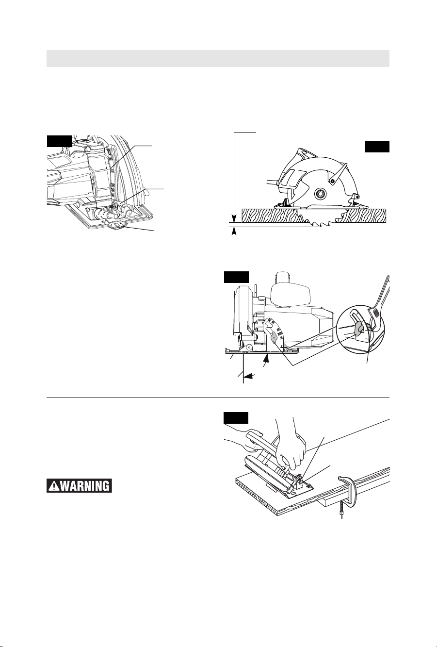
Do not use the saw with an excessive
depth of cut setting. Too much blade
exposure increases the likelihood of the blade
twisting in the kerf and increases the surface
area of the blade available for pinching that
leads to kickback.
Lower guard function
Check lower guard for proper closing
before each use. Do not operate the saw if
lower guard does not move freely and
close instantly. Never clamp or tie the lower
guard into the open position. If saw is
accidentally dropped, lower guard may be
bent. Raise the lower guard with the lower
guard lift lever and make sure it moves freely
and does not touch the blade or any other part,
in all angles and depths of cut.
Check the operation of the lower guard
spring. If the guard and the spring are not
operating properly, they must be serviced
before use. Lower guard may operate
sluggishly due to damaged parts, gummy
deposits, or a build-up of debris.
Lower guard should be retracted manually
only for special cuts such as “Plunge Cuts”
and “Compound Cuts”. Raise lower guard by
Lower Guard Lift lever and as soon as blade
enters the material, the lower guard must be
released. For all other sawing, the lower guard
should operate automatically.
Always observe that the lower guard is
covering the blade before placing saw
down on bench or floor. An unprotected,
coasting blade will cause the saw to walk
backwards, cutting whatever is in its path. Be
aware of the time it takes for the blade to stop
after switch is released.
Do not run the tool while carrying it at your
side. Lower guard may be opened by a
contact with your clothing. Accidental
contact with the spinning saw blade could
result in serious personal injury.
Periodically remove the blade, clean the
upper, lower guards and the hub area with
kerosene and wipe it dry, or blow it clean
with compressed air. Preventive maintenance
and properly operating guard will reduce the
probability of an accident
GFCI and personal protection devices like
electrician’s rubber gloves and footwear will
further enhance your personal safety.
Do not use AC only rated tools with a DC
power supply. While the tool may appear to
work, the electrical components of the AC
rated tool are likely to fail and create a hazard
to the operator.
Keep handles dry, clean and free from oil
and grease. Slippery hands cannot safely
control the power tool.
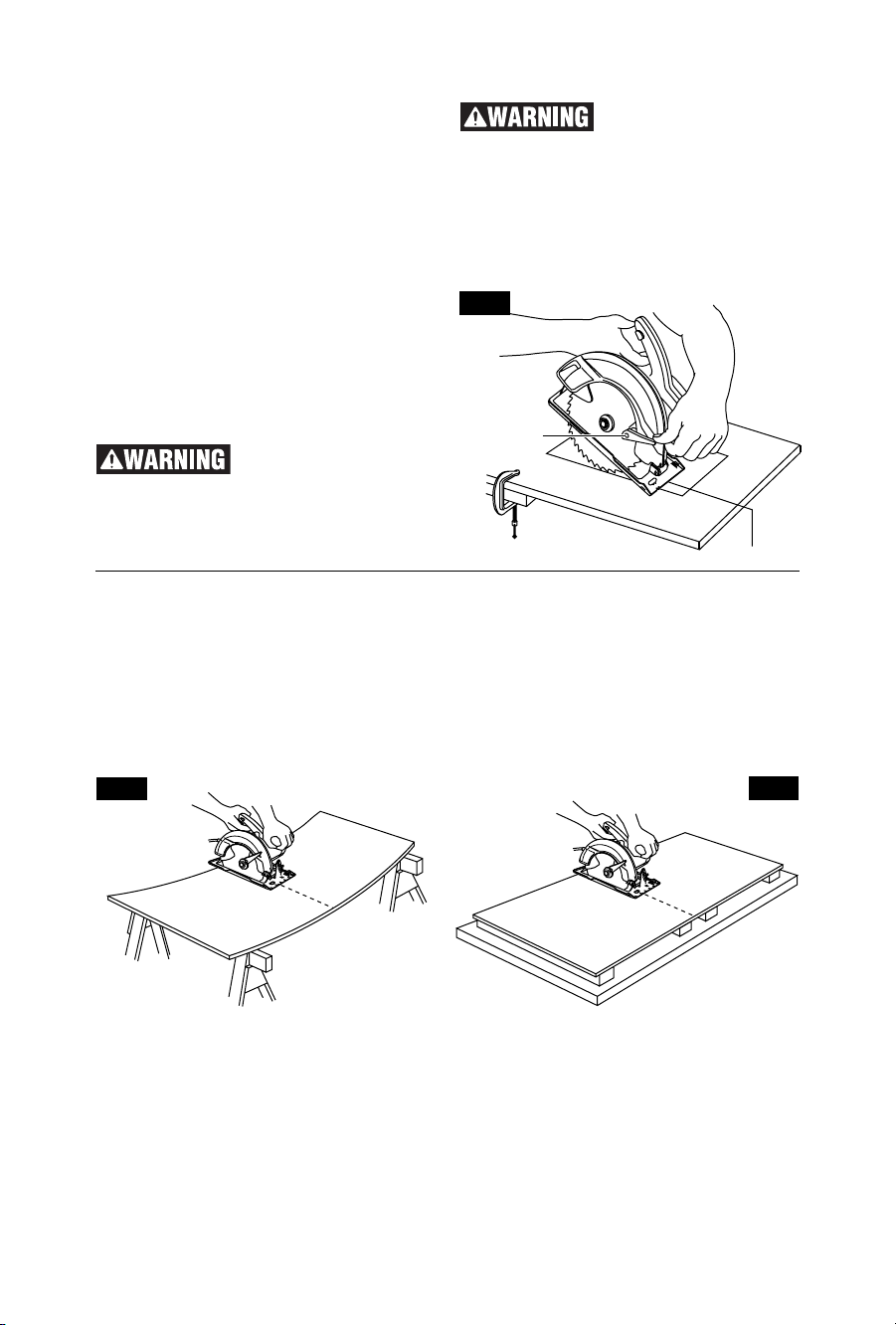
Use clamps or another practical way to
secure and support the workpiece to a
stable platform. Holding the work by hand or
against your body leaves it unstable and may
lead to loss of control.
Develop a periodic maintenance schedule
for your tool. When cleaning a tool be
careful not to disassemble any portion of
the tool since internal wires may be
misplaced or pinched or safety guard return
springs may be improperly mounted.
Certain cleaning agents such as gasoline,
carbon tetrachloride, ammonia, etc. may
damage plastic parts.
Risk of injury to user. The power cord must only
be serviced by a Skil Factory Service Center or
Autho rized Skil Service Station.
Some dust created by
power sanding, sawing,
grinding, drilling, and other construction
activities contains chemicals known to
cause cancer, birth defects or other
reproductive harm. Some examples of
these chemicals are:
Lead from lead-based paints,
Crystalline silica from bricks and cement and
other masonry products, and
Arsenic and chromium from chemically-
treated lumber.
Your risk from these exposures varies,
depending on how often you do this type of
work. To reduce your exposure to these
chemicals: work in a well ventilated area, and
work with approved safety equipment, such as
those dust masks that are specially designed
to filter out microscopic particles.
-6-
Symbols
IMPORTANT: Some of the following symbols may be used on your tool. Please study them
and learn their meaning. Proper interpretation of these symbols will allow you to operate the
tool better and safer.
Symbol Designation / Explanation
V Volts (voltage)
A Amperes (current)
Hz Hertz (frequency, cycles per second)
W Watt (power)
kg Kilograms (weight)
min Minutes (time)
s Seconds (time)
Diameter (size of drill bits, grinding wheels, etc.)
n0No load speed (rotational speed at no load)
n Rated speed (maximum attainable speed)
.../min Revolutions or reciprocation per minute (revolutions, strokes, surface speed,
orbits etc. per minute)
0 Off position (zero speed, zero torque...)
1, 2, 3, ...
I, II, III, Selector settings (speed, torque or position settings. Higher number means
greater speed)
0
Infinitely variable selector with off (speed is increasing from 0 setting)
Arrow (action in the direction of arrow)
Alternating current (type or a characteristic of current)
Direct current (type or a characteristic of current)
Alternating or direct current (type or a characteristic of current)
Class II construction (designates double insulated construction tools)
Earthing terminal (grounding terminal)
-7-
Symbols (continued)
IMPORTANT: Some of the following symbols may be used on your tool. Please study them
and learn their meaning. Proper interpretation of these symbols will allow you to operate the
tool better and safer.
Symbol Designation / Explanation
Designates Li-ion battery recycling program
Designates Ni-Cad battery recycling program
Alerts user to read manual
Alerts user to wear eye protection
This symbol designates that this tool is listed by Underwriters Laboratories.
This symbol designates that this component is recognized by Underwriters
Laboratories.
This symbol designates that this tool is listed by Underwriters Laboratories,
to United States and Canadian Standards.
This symbol designates that this tool is listed by the Canadian Standards
Association.
This symbol designates that this tool is listed by the Canadian Standards
Association, to United States and Canadian Standards.
This symbol designates that this tool is listed by the Intertek Testing
Services, to United States and Canadian Standards.
This symbol designates that this tool complies to NOM Mexican Standards.
-8-
Functional Description and Specifications
Disconnect the plug from the power source before making any
assembly, adjustments or changing accessories. Such preventive
safety measures reduce the risk of starting the tool accidentally.
FIG. 1
LOWER GUARD
FOOT
LOWER
GUARD LIFT
LEVER
AUXILIARY HANDLE
BEVEL
ADJUSTMENT
WING NUT
CALIBRATED
BEVEL
QUADRANT
SAFETY SWITCH
RELEASE BUTTON
UPPER GUARD
Circular Saws
Model number 5280
Maximum Capacities
Blade 7-1/4"
Blade arbor hole 5/8" Round
Depth of cut at 90° 2-7/16"
Depth of cut at 45° 1-15/16"
Depth of cut at 51° 1-11/16"
NOTE: For tool specifications refer to
the nameplate on your tool.
POWER INDICATOR LIGHT
TRIGGER LASER BUTTON
-9-
Assembly
ATTACHING THE BLADE
Disconnect the plug
from the power source
before making any assembly,
adjustments or changing accessories.
Such preventive safety measures reduce the
risk of starting the tool accidentally.
Use only 7 1/4” blade rated
5300/min (RPM) or greater.
Using blade not designed for the saw may result
in serious personal injury and property damage.
1. Press the lock button and turn wrench until
lock button en gages. Saw shaft is now locked.
Continue to depress button, turn wrench
counter-clockwise and remove BLADE STUD
and OUTER WASHER (Fig. 2).
2. Make sure the saw teeth and arrow on the
blade point in the same direction as the arrow
on the lower guard.
3. Retract the lower guard all the way up into
the upper guard. While retracting the lower
guard, check operation and condition of the
LOWER GUARD SPRING.
4. Slide blade through slot in the foot and
mount it against the INNER WASHER on the
shaft. Be sure the large diameter of the INNER
and OUTER washers lay flush against the
blade.
5. Reinstall OUTER WASHER. First tighten
BLADE STUD finger tight, then TIGHTEN
BLADE STUD 1/8 TURN (4) WITH THE
WRENCH PROVIDED.
Do not use wrenches with longer handles,
since it may lead to over tightening of the blade
stud.
VARI-TORQUE CLUTCH
This clutching action is provided by the friction
of the OUTER WASHER against the BLADE
and permits the blade shaft to turn when the
blade encounters excessive resistance. When
the BLADE STUD is properly tightened (as
described in No. 5 of Attaching The Blade), the
blade will slip when it encounters ex cessive
resistance, thus reducing saw’s tendency to
KICKBACK.
One setting may not be sufficient for cutting all
materials. If ex cessive blade slippage occurs,
tighten the blade stud a fraction of a turn more
(less than 1/8 turn). OVERTIGHTENING THE
BLADE STUD NULLIFIES THE EFFECTIVE-
NESS OF THE CLUTCH.
FIG. 2
Tighten
Loosen
BLADE STUD
LOWER GUARD
SPRING
OUTER WASHER
Large Diameter
Faces Blade
INNER WASHER
Large Diameter
Faces Blade
BLADE
LOWER GUARD
UPPER
GUARD
BLADE SHAFT
LOCK
BUTTON
FIG. 3
DEPTH
ADJUSTMENT
LEVER
DEPTH SCALE
Calibrated For Standard
Lumber Sizes
BLADE WRENCH
AND STORAGE AREA
90° CUTTING ANGLE CHECK
Disconnect plug from power source. Set foot to
maximum depth of cut setting. Loosen bevel
adjustment wing nut, set to on quadrant,
retighten wing nut and check for 90° angle
between the blade and bottom plane of foot with
a square (Fig. 5). If adjustment is necessary, tilt
foot to 4, tighten bevel adjustment wing nut
and bend "TAB" with an adjustable wrench or
pliers (Fig. 5).
-10-
DEPTH ADJUSTMENT
Disconnect plug from power source. Loosen
the depth adjustment lever located between
the guard and handle of saw. Hold the foot
down with one hand and raise or lower saw by
the handle. Tighten lever at the depth setting
desired. Check desired depth (Fig. 3).
Not more than one tooth length of the blade
should extend below the material to be cut, for
minimum splintering (Fig. 4).
BEVEL ADJUSTMENT
Disconnect plug from power source. The foot
can be adjusted up to 45° by loosening the
bevel adjustment wing nut at the front of the
saw. Align to desired angle on calibrated
quadrant. Then tighten bevel adjustment wing
nut (Fig. 6).
Because of the increased
amount of blade
engagement in the work and decreased
stability of the foot, blade binding may
occur. Keep the saw steady and the foot
firmly on the workpiece.
Operating Instructions
FIG. 4
FIG. 5
FIG. 6
ONE TOOTH LENGTH SHOULD
PENETRATE WOOD FOR
MINIMUM SPLINTERING
TAB
BEVEL ADJUSTMENT
WING NUT
BEVEL
ADJUSTMENT
WING NUT
QUADRANT
BLADE
FOOT 90°
-11-
USING THE LASER LINE GUIDE
Your tool is equipped with a laser line guide
that will turn on whenever the tool is plugged
in and the laser button is pushed in (Fig. 1).
The laser line is pre-set at the factory to the
kerf of the blade supplied with your saw.
If using the laser line guide for cutting you do
not need the line guide incorporated in the
foot as it may be in a different setting than the
laser line guide.
The laser light guide is a class IIIA laser with a
maximum output power of 5.0 mWatts and
conforms to 21 CFR 1040.10 and 1040.11.
LASER RADIATION.
AVOID DIRECT EYE
EXPOSURE. DO NOT stare into the laser
light source. Never aim light at another
person or object other than the workpiece.
Laser light can damage your eyes.
DO NOT use tinted
glasses to enhance the
laser light. Tinted glasses will reduce overall
vision for the application and interfere with the
normal operation of the tool.
Never aim the beam at a
workpiece with a
reflective surface. Bright shiny reflective
sheet steel or similar reflective surfaces are
not recommended for laser use. Reflective
surfaces could direct the beam back toward
the operator.
Use of controls or
adjustments or
performance of procedures other than those
specified herein may result in hazardous
radiation exposure.
The use of optical
instruments with this
product will increase eye hazards.
USING THE GUIDE NOTCHES
WITHOUT LASER LINE
For a straight 90° cut, use right side of notch
in the foot. For 45° bevel cuts, use the left side
(Fig. 7a). The cutting guide notch will give an
approximate line of cut. Make sample cuts in
scrap lumber to verify actual line of cut. This
will be helpful because of the number of
different blade types and thicknesses
available. To ensure minimum splintering on
the good side of the material to be cut, face
the good side down.
FIG. 7a
45°
BEVEL
CUTS
90°
VERTICAL
CUTS
FIG. 7
-12-
POWER INDICATOR LIGHT
When you plug your tool into the power
source, the power indicator light will go “ON
indicating the tool is receiving power (Fig. 1).
SAFETY SWITCH
The safety switch is designed to prevent
accidental starts. To operate safety switch, press
the release button with your thumb on either side
of handle to disengage the lock, then pull the
trigger (Fig. 1). When the trigger is released the
button will engage the safety switch
automatically, and the trigger will no longer
operate. (See SWITCH and GENERAL CUTS.)
SWITCH
When starting the tool,
hold it with both hands.
The torque from the motor can cause the tool
to twist.
To turn tool on, press the safety switch
release button with your thumb on either side
of handle to disengage the lock, then pull the
trigger (Fig. 1). To turn the tool off, release the
trigger switch, which is spring loaded and will
return to the off position automatically.
Your saw should be running at full speed
BEFORE starting the cut, and turned off only
AFTER completing the cut. To increase switch
life, do not turn switch on and off while cutting.
GENERAL CUTS
Always hold the saw handle with one hand
and the auxiliary handle or housing with the
other.
Always be sure either
hand does not interfere
with the free movement of the lower guard.
Maintain a firm grip and operate the switch
with a decisive action. Never force the saw.
Use light and continuous pressure.
After completing a cut
and the trigger has been
released, be aware of the nec es sary time it
takes for the blade to come to a com plete
stop during coast down. Do not allow the
saw to brush against your leg or side,
since the lower guard is retractable, it
could catch on your clothing and expose
the blade. Be aware of the necessary blade
ex posures that exist in both the upper and
lower guard areas.
When cutting is interrupted, to resume cutting:
squeeze the trigger and allow the blade to
reach full speed, re-enter the cut slowly and
resume cutting.
When cutting across the grain, the fibers of
the wood have a ten den cy to tear and lift.
Advancing the saw slowly minimizes this
effect. For a finished cut, a cross cut blade or
miter blade is rec om mended.
CUTTING MASONRY/METAL
This tool is not designed for use with metal or
masonry cut-off wheels.
Do not use abrasive
wheels with circular
saws. Abrasive dust may cause lower
guard to fail.
WRENCH STORAGE
Wrench storage is provided on the tool (Fig. 3).
Wrench is fully seated when second lock detent
is engaged.
Wrench needs to be
inserted with the correct
orientation (Fig. 8). Damage to work piece
could occur if inserted incorrectly.
FIG. 8
FOOT
BLADE
WRENCH
-13-
PLUNGE CUTS
Disconnect the plug from the power source
before making adjustments. Set depth
adjustment according to material to be cut.
Reconnect the plug to power source.
Hold the main handle of the saw with one
hand, tilt saw forward and rest front of the foot
plate on material to be cut. Line up the cutting
guide notch with the line you’ve drawn. Raise
the lower guard using lower guard lift lever
and hold the front of the foot plate with the
other hand. (Fig. 9).
Position the saw with the blade just clearing
the material to be cut. Start the motor and
once fully up to speed, gradually lower the
back end of saw using the front end of the foot
as the hinge point.
Once the foot plate rests
flat on the surface being
cut, release the lower guard and move the
hand holding the front of the foot plate to
hold the auxiliary handle. Proceed cutting in
forward direction to end of cut.
Allow blade to come to a
complete stop before
lifting the saw from cut. Also, never pull
the saw backward since blade will climb
out of the material and KICKBACK will
occur. Turn saw around and finish the cut in
the normal manner, sawing forward. If corners
of your plunge cut are not completely cut
through, use a jigsaw or hand saw to finish the
corners.
FIG. 11
RIGHT
FIG. 10
WRONG
CUTTING LARGE SHEETS
Large sheets and long boards sag or bend,
depending on support. If you attempt to cut
without leveling and properly supporting the
piece, the blade will tend to bind, causing KICK-
BACK and extra load on the motor (Fig. 10).
Support the panel or board close to the cut, as
shown in (Fig. 11). Be sure to set the depth of
the cut so that you cut through the sheet or
board only and not the table or work bench. The
two-by-fours used to raise and support the work
should be positioned so that the broadest sides
support the work and rest on the table or bench.
Do not support the work with the narrow sides
as this is an unsteady arrangement. If the sheet
or board to be cut is too large for a table or work
bench, use the supporting two-by-fours on the
floor and secure.
FIG. 9
FOOT
LOWER
GUARD LIFT
LEVER
Service
Preventive maintenance
performed by unautho -
rized personnel may result in misplacing of
internal wires and components which
could cause serious hazard. We
recommend that all tool service be performed
by a Bosch Factory Service Center or Autho -
rized Bosch Service Station.
TOOL LUBRICATION
Your Skil tool has been properly lubricated
and is ready to use. It is recommended that
tools with gears be regreased with a special
gear lubricant at every brush change.
CARBON BRUSHES
The brushes and commutator in your tool
have been engineered for many hours of
dependable service. To maintain peak
efficiency of the motor, we recommend every
two to six months the brush es be examined.
Only genuine Skil replace ment brushes
specially designed for your tool should be
used.
BEARINGS
Bearings which become noisy (due to heavy
load or very abrasive material cut ting) should
be replaced at once to avoid overheating or
motor failure.
Cleaning
To avoid accidents
always dis connect the
tool from the power supply before cleaning
or performing any main tenance. The tool
may be cleaned most effectively with
compressed dry air. Always wear safety
gog gles when cleaning tools with
compressed air.
Ventilation openings and switch levers must
be kept clean and free of foreign matter. Do
not at tempt to clean by inserting pointed
objects through openings.
Certain cleaning agents
and sol vents damage
plastic parts. Some of these are: gasoline,
carbon tetrachlo ride, chlo rinated cleaning
solvents, ammonia and house hold detergents
that contain ammonia.
Maintenance
-14-
RIP CUTS
The combination blade provided with your saw
is for both cross cuts and rip cuts. Ripping is
cutting lengthwise with the grain of the wood.
Rip cuts are easy to do with a rip fence (Fig.
12). Rip Fence is available as an accessory (not
included). To attach fence, insert fence through
slots in foot to desired width as shown and
secure with the wing nut (not included).
Ensure rip fence does not
interfere with the free
movement of the lower guard and saw
blade. Rip fence contacting lower guard or
blade can cause property damage and serious
personal injury.
RIP BOARD GUIDE
When rip cutting large sheets, the rip fence
may not allow the desired width of cut. Clamp
or nail a straight piece of 1" (25 mm) lumber to
the sheet as a guide (Fig. 13). Use the right
side of the foot against the board guide.
Ensure the clamps do
not interfere with the free
movement of the saw.
FIG. 12
RIP FENCE
WING NUT
DESIRED
WIDTH OF CUT
DESIRED LINE
OF CUT
RIP BOARD
GUIDE
FIG. 13
-15-
Accessories
If an extension cord is
necessary, a cord with
adequate size conductors that is capable
of carrying the current necessary for your
tool must be used. This will prevent
excessive voltage drop, loss of power or
overheating. Grounded tools must use 3-wire
extension cords that have 3-prong plugs and
receptacles.
NOTE: The smaller the gauge number, the
heavier the cord.
RECOMMENDED SIZES OF EXTENSION CORDS
120 VOLT ALTERNATING CURRENT TOOLS
*Blade 1619X09434
*Wrench 1619X07602
** Rip Fence 95100
** Carrying bag 1619X09514
(*= standard equipment)
(**= optional accessories)
CARE OF BLADES
Blades become dull even from cutting regular
lumber. If you find yourself forcing the saw
forward to cut instead of just guid ing it through
the cut, chances are the blade is dull or coated
with wood pitch.
When cleaning gum and wood pitch from
blade, unplug the saw and remove the blade.
Remember, blades are designed to cut, so
handle carefully. Wipe the blade with kerosene
or similar sol vent to remove the gum and pitch.
Unless you are experienced in sharpening
blades, we recommend you do not try.
Extension Cords
Tool’s
Ampere
Rating
Cord Size in A.W.G. Wire Sizes in mm2
Cord Length in Feet Cord Length in Meters
25 50 100 150 15 30 60 120
3-6
6-8
8-10
10-12
12-16
18
18
18
16
14
16
16
16
16
12
16
14
14
14
14
12
12
12
0.75
0.75
0.75
1.0
0.75
1.0
1.0
2.5
1.5
2.5
2.5
4.0
2.5
4.0
4.0
The use of any other acces so ries not specified in this manual may create a hazard.
Troubleshooting
Read instruction manual first! Remove plug from the power source before
making adjustments or assembling the blade.
TROUBLE: SAW WILL NOT START
PROBLEM 1. Power cord is not plugged in.
2. Power source fuse or circuit breaker tripped.
3. Cord damaged.
4. Burned out switch.
5. Trigger does not turn tool on.
REMEDY 1. Plug saw in.
2. Replace fuse or reset tripped circuit breaker.
3. Inspect cord for damage. If damaged, have cord replaced by an Authorized Skil
Service Center or Service Station.
4. Have switch replaced by an Authorized Skil Service Center or Service Station.
5. Disengage Safety Switch as described on page 12
TROUBLE: BLADE DOES NOT COME UP TO SPEED
PROBLEM 1. Extension cord too light or too long.
2. Low house voltage.
REMEDY 1. Replace with adequate cord.
2. Contact your electric company.
TROUBLE: EXCESSIVE VIBRATION
PROBLEM 1. Blade out of balance.
2. Workpiece not clamped or supported properly.
REMEDY 1. Discard Blade and use different blade.
2. Clamp or support workpiece as shown on pages 10 and 13.
TROUBLE: CANNOT MAKE SQUARE CUT WHEN CROSSCUTTING
PROBLEM 1. Foot not adjusted properly.
REMEDY 1. See “Operating Instructions” section, “Bevel Adjustment” (page 10), “Line
Guide” (page 11), “Cutting Large Sheets (page 13) and “Rip Cuts” (page 14).
TROUBLE: CUT BINDS, BURNS, STALLS MOTOR WHEN RIPPING
PROBLEM 1. Dull blade with improper tooth set.
2. Warped board.
3. Blade binds.
4. Improper workpiece support.
REMEDY 1. Discard blade and use a different blade.
2. Make sure concave or hollow side is facing “DOWN” feed slowly, see page 13.
3. Assemble blade and tighten Vari-Torque clutch per “Assembly Instructions”, see
page 9.
4. Clamp or support workpiece as shown on pages 10 and 13.
TROUBLE: BLADE SLIPPING
PROBLEM 1. Tool does not cut workpiece.
REMEDY 1. Assemble blade and tighten Vari-Torque clutch per “Assembly Instructions”, see
page 9.
-16-
10

Hulp nodig? Stel uw vraag in het forum

Spelregels

Misbruik melden

Gebruikershandleiding.com neemt misbruik van zijn services uitermate serieus. U kunt hieronder aangeven waarom deze vraag ongepast is. Wij controleren de vraag en zonodig wordt deze verwijderd.

Product:

Bijvoorbeeld antisemitische inhoud, racistische inhoud, of materiaal dat gewelddadige fysieke handelingen tot gevolg kan hebben.

Bijvoorbeeld een creditcardnummer, een persoonlijk identificatienummer, of een geheim adres. E-mailadressen en volledige namen worden niet als privégegevens beschouwd.

Spelregels forum

Om tot zinvolle vragen te komen hanteren wij de volgende spelregels:

Belangrijk! Als er een antwoord wordt gegeven op uw vraag, dan is het voor de gever van het antwoord nuttig om te weten als u er wel (of niet) mee geholpen bent! Wij vragen u dus ook te reageren op een antwoord.

Belangrijk! Antwoorden worden ook per e-mail naar abonnees gestuurd. Laat uw emailadres achter op deze site, zodat u op de hoogte blijft. U krijgt dan ook andere vragen en antwoorden te zien.

Abonneren

Abonneer u voor het ontvangen van emails voor uw Skil 5280 bij:


U ontvangt een email met instructies om u voor één of beide opties in te schrijven.


Ontvang uw handleiding per email

Vul uw emailadres in en ontvang de handleiding van Skil 5280 in de taal/talen: Engels als bijlage per email.

De handleiding is 1,48 mb groot.


U ontvangt de handleiding per email binnen enkele minuten. Als u geen email heeft ontvangen, dan heeft u waarschijnlijk een verkeerd emailadres ingevuld of is uw mailbox te vol. Daarnaast kan het zijn dat uw internetprovider een maximum heeft aan de grootte per email. Omdat hier een handleiding wordt meegestuurd, kan het voorkomen dat de email groter is dan toegestaan bij uw provider.

Stel vragen via chat aan uw handleiding

Stel uw vraag over deze PDF

Uw handleiding is per email verstuurd. Controleer uw email

Als u niet binnen een kwartier uw email met handleiding ontvangen heeft, kan het zijn dat u een verkeerd emailadres heeft ingevuld of dat uw emailprovider een maximum grootte per email heeft ingesteld die kleiner is dan de grootte van de handleiding.

Er is een email naar u verstuurd om uw inschrijving definitief te maken.

Controleer uw email en volg de aanwijzingen op om uw inschrijving definitief te maken

U heeft geen emailadres opgegeven

Als u de handleiding per email wilt ontvangen, vul dan een geldig emailadres in.

Uw vraag is op deze pagina toegevoegd

Wilt u een email ontvangen bij een antwoord en/of nieuwe vragen? Vul dan hier uw emailadres in.


Info