648539
4
Verklein
Vergroot
Pagina terug
1/52
Pagina verder
WLR-9500
User Manual
Table of Contents
Introduction ............................................................................................................ 3
Package Contents ..................................................................................................... 5
Cautions ................................................................................................................ 6
Product Layout......................................................................................................... 7
Network + System Requirements ...................................................................................10
Setup your Router ....................................................................................................11
Setup your Computer ................................................................................................12
Login to your Router .................................................................................................15
Configure your Internet connection ...............................................................................16
Configure your Router ...............................................................................................19
Wireless Settings ......................................................................................................24
Firewall Settings ......................................................................................................33
Advanced Settings ...................................................................................................38
Toolbox Settings ......................................................................................................45
Revision 1.0
© Sitecom Europe BV 2016
Note: All the information contained in this manual was correct at the time of publication.
However, as our engineers are always updating and improving the product, your device’s
software may have a slightly different appearance or modified functionality than presented in
this manual.
Introduction
Congratulations on your purchase of the AC2600 WiFi Router. This router is compliant with
802.11a/b/g/n/ac and up to 6 times faster than standard 802.11n based routers while still being
compatible with 802.11g & 802.11b devices. This router is not only a Wireless Access Point, but
also doubles as a 4-port full-duplex Gigabit switch that connects your wired-Ethernet devices
together at 10/100/1000 Mbps speeds.
At 800Mbps wireless transmission rate on 2.4GHz and 1750 Mbps wireless transmission rate on
5GHz, the Access Point built into the router uses advanced MIMO (Multi-Input, Multi-Output)
technology to transmit multiple streams of data in a single wireless channel, giving you
seamless access to multimedia content. The robust RF signal travels farther, eliminates dead
spots and extends the network range. For data protection and privacy, the router encodes all
wireless transmissions with WEP, WPA, or WPA2 encryption.
With the built-in DHCP Server & powerful SPI firewall, the router protects your computers
against intruders and most known Internet attacks and also provides safe VPN pass-through.
With the incredible speed and QoS function of 802.11n, the router is ideal for media-centric
applications like streaming video, gaming, and VoIP telephony to run multiple media-intense
data streams through the network at the same time, with no degradation in performance.
Key Features
Features
Advantages
Incredible Data Rate up to 1750Mbps*
Heavy data payloads such as MPEG video
streaming
IEEE 802.11n Compliant and backwards
compatible with 802.11b/g/n
Fully Interoperable with IEEE 802.11b /
IEEE802.11g, IEEE 802.11n compliant
devices with legacy protection
Four 10/100/1000 Mbps gigabit Switch
Ports (Auto-Crossover)
Scalability, extend your network.
Firewall supports Virtual Server
Mapping, DMZ, IP Filter, ICMP Blocking,
SPI
Avoids the attacks of Hackers or Viruses
from Internet
Support 802.1x authenticator, 802.11i
(WPA/WPA2, AES), VPN pass-through
Provide mutual authentication (Client and
dynamic encryption keys to enhance
security
USB Ports
Connect a USB storage device and share it
in your network.
Guest Network
Devices connected to the Guest network
will have Internet connection but no access
to the main network and cannot
communicate with each other.
IPv6 support
Support for Static, Native, 6RD and DS-Lite.
* Theoretical wireless signal rate based on IEEE standard of 802.11a, b, g, n, ac chipset used.
Actual throughput may vary. Network conditions and environmental factors lower actual
throughput rate. All specifications are subject to change without notice.
Package Contents
Open the package carefully, and make sure that none of the items listed below are missing. Do
not discard the packing materials, in case of return; the unit must be shipped back in its original
package.
Cautions
This router’s design and manufacturer has your safety in mind. In order to safely and effectively
use this router, please read the following before usage.
Usage Cautions
The user should not modify this router. The environmental temperature should be within +5 ~
+35 degrees Celsius.
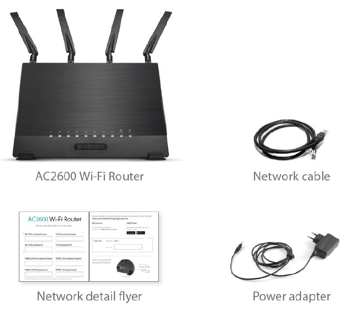
Power
The router’s power voltage is DC 12V 1.5A.
When using this router, please connect the supplied AC adapter or AC adapter cable to the
router’s power jack. When placing the adapter cable, make sure it can’t get damaged or be
subject to pressure. To reduce the risk of electric shock, unplug the adapter first before cleaning
it. Never connect the adapter to the router in a humid or dusty area. Do not replace the adapter
or cable’s wire or connector.
Repair
If the router has a problem, you should take it to an appointed repair center and let the
specialists do the repair. Never repair the router yourself, you might damage the router or
endanger yourself.
Disposing of the Router
When you dispose of the router, be sure to dispose it appropriately. Some countries may
regulate disposal of an electrical device, please consult with your local authority.
Others
When using this router, please do not let it come into contact with water or other liquids. If
water is accidentally spilled on the router, please use a dry cloth to absorb the spillage.
Electronic products are vulnerable, when using please avoid shaking or hitting the router, and
do not press the buttons too hard.
Do not let the router come into contact with water or other liquid.
Do not disassemble, repair or change the design of the router; any damage done will
not be included in the repair policy.
Avoid hitting the router with a hard object, avoid shaking the router and stay away from
magnetic fields.
If during electrostatic discharge or a strong electromagnetic field the product will
malfunction, unplug the power cable. The product will return to normal performance
the next time it is powered on.
Product Layout
Port
Description
Power connector
Connect the 12V DC adapter to this port
LAN (Black)
Connect your PCs or network devices to these ports
WAN (Grey)
Connect your ADSL/Cable modem to this port
USB Port
Connect a USB device to this port
Backlabel and Network Details Folder
The Network Details Folder describes the IP address, login details, network name, security code
and OPS button functionality.
Button
Description
OPS Button
Press 2 seconds for WPS/OPS mode
Reset
Push a pin in the reset hole to reset to factory defaults.
LED Definition
As shown from the top to the bottom.
LED
Description
Power
Shows the device is turned on.
Internet
Shows the device is connected to the internet.
LAN
Shows the cable is connected.
LAN
Shows the cable is connected.
LAN
Shows the cable is connected.
LAN
Shows the cable is connected.
USB1
Shows a device is connected to the USB port.
USB2
Shows a device is connected to the USB port.
2.4GHz WiFi
Shows 2.4GHz WiFi activity.
5GHz WiFi
Shows 5GHz WiFi activity.
Network + System Requirements
To begin using the router, make sure you meet the following as minimum requirements:
Network Requirements
An Ethernet-based broadband modem
Web-based Configuration
Computer with the following:
- Windows®, Macintosh, or Linux-based operating
system
- An installed Ethernet adapter or wireless adapter
- Supported Browsers:
Internet Explorer 9 or higher
Firefox
Safari 4 or higher
Chrome
Setup your Router
You can place the router on a desk or other flat surface, or you can mount it on a wall. For
optimal performance, place your router in the center of your home (or your office) in a location
that is away from any potential source of interference, such as a metal wall or microwave oven.
This location must be close to a power connection and your ADSL/Cable modem.
Connect the supplied power-adapter to the power inlet port and connect it to a wall outlet.
Switch the router on by pushing the switch on the back of the device. The router automatically
enters the self-test phase. During self-test phase, the Power LED will be lit continuously to
indicate that this product is in normal operation.
Setup your Computer
Windows, Manual Connection
Click on the icon for wireless connectivity. This is usually located in the System Tray, next
to the clock.
Select the Sitecom network. The correct network name can be found on the sticker on
bottom of the router, or in the Network Details Folder.
Fill in the password for the wireless network. The correct password can be found on the
sticker on the bottom of the router, or in the Network Details Folder.
Wait for the icon to display that it’s connected to the network.
Windows, OPS Connection
Click on the icon for wireless connectivity. This is usually located in the System Tray, next
to the clock.
Select the Sitecom network. The correct network name can be found on the sticker on
bottom of the router, or in the Network Details Folder.
Push the OPS Button on the router. For 2.4GHz, press 0-5 seconds. For 5GHz, press 5-10
seconds.
Wait for the icon to display that it’s connected to the network.
Mac OSX
Click on the icon for wireless connectivity. This is usually located in the System Tray, next
to the clock.
Select the Sitecom network. The correct network name can be found on the sticker on
bottom of the router, or in the Network Details Folder.
Fill in the password for the wireless network. The correct password can be found on the
sticker on the bottom of the router, or in the Network Details Folder.
Wait for the icon to display that it’s connected to the network.
Login to your Router
LOGIN procedure
OPEN your browser (e.g. Internet Explorer).
Type http://sitecom.router in the address bar and press [Enter].
Type user name and password. The default username is admin, the password can be
found on the back label on the bottom of your router.
Click OK.
You will see the home page of the AC2600 WiFi Router.
Configure your Internet connection
From the menu, select “Internet Settings”.
Depending on the chosen setting, you may need to enter your user name and password, MAC
address or hostname in the following window. After you have entered the correct information,
click Apply.
IPv6 Configuration
The IPv6 (Internet Protocol version 6) section is where you configure your IPv6 Connection type.
IPv6 Connection Type
There are several connection types to choose from: Static IPv6, Autoconfiguration, 6RD and
Link-local only. If you are unsure of your connection method, please contact your IPv6 Internet
Service Provider.
Static IPv6 Mode
This mode is used when your ISP provides you with a set IPv6 addresses that does not change.
The IPv6 information is manually entered in your IPv6 configuration settings. You must enter
the IPv6 address, Subnet Prefix Length, Default Gateway, Primary DNS Server and Secondary
DNS Server. Your ISP provides you with all this information.
6RD Mode
In the 6RD mode, no additional configuration is necessary.
Link-local Mode
The Link-local address is used by nodes and routers when communicating with neighboring
nodes on the same link. This mode enables IPv6-capable devices to communicate with each
other on the LAN side.
Configure your Router
Status
The System status section allows you to monitor the current status of your router, the UP time,
hardware information and serial number as well as firmware version information is displayed
here.
DHCP Server
The DHCP Server tab gives you the opportunity to change the IP settings of the router.
Click Apply at the bottom of this screen to save any changes.
IP address 192.168.0.1: It is the router’s LAN IP address (Your LAN clients default
gateway IP address).
IP Subnet Mask 255.255.255.0: Specify a Subnet Mask for your LAN segment.
802.1d Spanning Tree: Disabled by default. If the 802.1d Spanning Tree function is
enabled, this router will use the spanning tree protocol to prevent network loops.
DHCP Server: Enabled by default. You can enable or disable the DHCP server. When
DHCP is disabled no ip-addresses are assigned to clients and you have to use static
ip-addresses. When DHCP server is enabled your computers will be assigned an ip-
address automatically until the lease time expires.
Lease Time: One Week. In the Lease Time setting you can specify the time period
that the DHCP lends an IP address to your LAN clients. The DHCP will change your
LAN client’s IP address when this time threshold period is reached.
IP Address Pool: You can select a particular IP address range for your DHCP server to
issue IP addresses to your LAN Clients. The default IP range is 192.168.0.100 ~
192.168.0.200. If you want your PC(s) to have a static/fixed IP address, then you’ll
have to choose an IP address outside this IP address Pool
Domain Name: You can specify a Domain Name for your LAN or just keep the default
(sitecom.router).
Device Status
View the router’s current configuration settings. Device Status displays the configuration
settings you’ve configured in the Internet Settings and WiFi Settings sections.
DHCP Client Status
This page shows all DHCP clients (LAN PCs) currently connected to your network. The table
shows the assigned IP address, MAC address and expiration time for each DHCP leased client.
Use the Refresh button to update the available information.
You can check Enable Static DHCP IP. It is possible to add more static DHCP IPs. They are listed
in the table Current Static DHCP Table. IP can be deleted at will from the table.
Click Apply to save the changed configuration.
Log
View the operation log of the router. This page shows the current system log of the router. It
displays any event that occurred during or after system start up. At the bottom of the page, the
system log can be saved <Save> to a local file for further processing or the system log can be
cleared <Clear> or it can be refreshed <Refresh> to get the most updated information. When
the system is powered down, the system log will disappear if not saved to a local file.
Statistics
Shows the counters of packets sent and received on WAN, LAN & WLAN.
Wireless Settings
You can set parameters that are used for the wireless stations to connect to this router for the
2.4 GHz radio or 5 GHz radio. The parameters include Mode, ESSID, Channel Number and
Associated Client.
Wireless Function
Enable or Disable Wireless function here. Click Apply and wait for module to be ready & loaded.
Basic Settings
Band: Allows you to set the AP fixed at 802.11b or 802.11g mode. You can also select
B+G mode to allow 802.11b and 802.11g clients at the same time. For the 5GHz
mode you can set 802.11a, 802.11n, 802.11a/n or 802.11ac mode.
Guest Network: Enable this to activate the Guest Network. Devices connected to the
Guest network will have Internet connection but no access to the main network and
cannot communicate with each other
SSID: This is the name of the wireless signal which is broadcasted. All the devices in
the same wireless LAN should have the same SSID.
Channel: The channel used by the wireless LAN. All devices in the same wireless LAN
should use the same channel.
Guest Network
Guest IP address: The gateway address for the Guest Network. This address cannot
be the same as the default router’s IP Address.
Guest Subnet Mask: The Subnet Mask for the Guest network. This address cannot be
the same as the default router’s Subnet Mask.
Guest Lease Time: One Week. In the Lease Time setting you can specify the time
period that the DHCP lends an IP address to your LAN clients. The DHCP will change
your LAN client’s IP address when this time threshold period is reached.
Guest Start IP + End IP: You can select a particular IP address range for your DHCP
server to issue IP addresses to your LAN Clients. The default IP range is
192.168.169.100 ~ 192.168.169.200. This address pool cannot be the same as the
default router’s DHCP Address pool.
Guest SSID: This is the name of the wireless signal which is broadcasted as the Guest
Network. This name cannot be the same as the default SSID.
Advanced Settings
This tab allows you to set the advanced wireless options. The options included are, Fragment
Threshold, RTS Threshold, Beacon Interval, and Preamble Type. You should not change these
parameters unless you know what effect the changes will have on the router.
Fragment Threshold: "Fragment Threshold" specifies the maximum size of a packet
during the fragmentation of data to be transmitted. If you set this value too low, it
will result in bad performance.
RTS Threshold: When the packet size is smaller then the RTS threshold, the wireless
router will not use the RTS/CTS mechanism to send this packet.
Beacon Interval: This is the interval of time that this wireless router broadcasts a
beacon. A Beacon is used to synchronize the wireless network.
Data Rate: The “Data Rate” is the rate that this access point uses to transmit data
packets. The access point will use the highest possible selected transmission rate to
transmit the data packets.
N Data Rate: The “Data Rate” is the rate that this access point uses to transmit data
packets for N compliant wireless nodes. Highest to lowest data rate can be fixed.
Channel Bandwidth: This is the range of frequencies that will be used.
Preamble Type: The “Long Preamble” can provide better wireless LAN compatibility
while the “Short Preamble” can provide better wireless LAN performance.
TX Power: The transmit power can be set to a bare minimum or maximum power for
better performance or power saving.
Security
This router provides complete wireless LAN security functions, included are WEP, IEEE 802.11x,
IEEE 802.11x with WEP, WPA with pre-shared key and WPA with RADIUS. With these security
functions, you can prevent your wireless LAN from illegal access. Please make sure your wireless
stations use the same security function, and are setup with the same security key.
Disable
When you choose to disable encryption, it is very insecure to use the router.
Enable 802.1x Authentication
IEEE 802.1x is an authentication protocol. Every user must use a valid account to login to this
Access Point before accessing the wireless LAN. The authentication is processed by a RADIUS
server. This mode only authenticates users by IEEE 802.1x, but it does not encrypt the data
during communication
WEP
When you select 64-bit or 128-bit WEP key, you have to enter WEP keys to encrypt data. You can
generate the key by yourself and enter it. You can enter four WEP keys and select one of them
as a default key. Then the router can receive any packets encrypted by one of the four keys.
Key Length: You can select the WEP key length for encryption, 64-bit or 128-bit. The
larger the key will be the higher level of security is used, but the throughput will be
lower.
Key Type: You may select ASCII Characters (alphanumeric format) or Hexadecimal
Digits (in the "A-F", "a-f" and "0-9" range) to be the WEP Key.
Key1 - Key4: The WEP keys are used to encrypt data transmitted in the wireless
network. Use the following rules to setup a WEP key on the device. 64-bit WEP: input
10-digits Hex values (in the "A-F", "a-f" and "0-9" range) or 5-digit ASCII character as
the encryption keys. 128-bit WEP: input 26-digit Hex values (in the "A-F", "a-f" and "0-
9" range) or 13-digit ASCII characters as the encryption keys.
Click Apply at the bottom of the screen to save the above configuration.
WPA Pre-shared Key
Wi-Fi Protected Access (WPA) is an advanced security standard. You can use a pre-shared key to
authenticate wireless stations and encrypt data during communication. It uses TKIP or CCMP
(AES) to change the encryption key frequently, so the encryption key is not easy to be cracked
by hackers. This is the best security available.
WPA-Radius
Wi-Fi Protected Access (WPA) is an advanced security standard. You can use an external RADIUS
server to authenticate wireless stations and provide the session key to encrypt data during
communication. It uses TKIP or CCMP (AES) to change the encryption key frequently. Press
Apply when you are done.
ACL
This wireless router supports MAC Address Control, which prevents unauthorized clients from
accessing your wireless network.
Enable wireless access control: Enables the wireless access control function
Adding an address into the list: Enter the "MAC Address" and "Comment" of the
wireless station to be added and then click "Add". The wireless station will now be
added into the "Current Access Control List" below. If you are having any difficulties
filling in the fields, just click "Clear" and both "MAC Address" and "Comment" fields
will be cleared.
Remove an address from the list: If you want to remove a MAC address from the
"Current Access Control List ", select the MAC address that you want to remove in
the list and then click "Delete Selected". If you want to remove all the MAC addresses
from the list, just click the "Delete All" button. Click "Reset" will clear your current
selections.
Click Apply at the bottom of the screen to save the above configurations. You can now
configure other sections by choosing Continue, or choose Apply to apply the settings and
reboot the device.
WPS
Wi-Fi Protected Setup (WPS) is the simplest way to establish a connection between the wireless
clients and the wireless router. You don’t have to select the encryption mode and fill in a long
encryption passphrase every time when you try to setup a wireless connection. You only need
to press a button on both wireless client and wireless router, and WPS will do the rest for you.
The wireless router supports two types of WPS: WPS via Push Button and WPS via PIN code. If
you want to use the Push Button, you have to push a specific button on the wireless client or in
the utility of the wireless client to start the WPS mode, and switch the wireless router to WPS
mode. You can simply push the WPS button of the wireless router, or click the ‘Start to Process’
button in the web configuration interface. If you want to use the PIN code, you have to know
the PIN code of the wireless client and switch it to WPS mode, then fill-in the PIN code of the
wireless client through the web configuration interface of the wireless router.
WPS: Check the box to enable WPS function and uncheck it to disable the WPS
function.
WPS Current Status: If the wireless security (encryption) function of this wireless
router is properly set, you’ll see a ‘Configured’ message here. Otherwise, you’ll see
‘UnConfigured’.
Self-Pin Code: This is the WPS PIN code of the wireless router. You may need this
information when connecting to other WPS-enabled wireless devices.
SSID: This is the network broadcast name (SSID) of the router.
Authentication Mode: It shows the active authentication mode for the wireless
connection.
Passphrase Key: It shows the passphrase key that is randomly generated by the
wireless router during the WPS process. You may need this information when using
a device which doesn’t support WPS.
WPS via Push Button: Press the button to start the WPS process. The router will wait
for the WPS request from the wireless devices within 2 minutes.
WPS via PIN: You can fill-in the PIN code of the wireless device and press the button
to start the WPS process. The router will wait for the WPS request from the wireless
device within 2 minutes.
Firewall Settings
The router provides extensive firewall protection by restricting connection parameters, thus
limiting the risk of hacker attacks, and defending against a wide array of common Internet
attacks. However, for applications that require unrestricted access to the Internet, you can
configure a specific client/server as a Demilitarized Zone (DMZ).
Note: To enable the Firewall settings select Enable and click Apply
DMZ
If you have a client PC that cannot run an Internet application (e.g. Games) properly from
behind the NAT firewall, then you can open up the firewall restrictions to unrestricted two-way
Internet access by defining a DMZ Host. The DMZ function allows you to re-direct all packets
going to your WAN port IP address to a particular IP address in your LAN. The difference
between the virtual server and the DMZ function is that the virtual server re-directs a particular
service/Internet application (e.g. FTP, websites) to a particular LAN client/server, whereas DMZ
re-directs all packets (regardless of services) going to your WAN IP address to a particular LAN
client/server.
Enable DMZ: Enable/disable DMZ
Public IP Address: The IP address of the WAN port or any other Public IP addresses given
to you by your ISP
Client PC IP Address: Fill-in the IP address of a particular host in your LAN that will
receive all the packets originally going to the WAN port/Public IP address above.
Click Apply at the bottom of the screen to save the above configurations.
Denial of Service (DoS)
The Broadband router's firewall can block common hacker attacks, including Denial of Service,
Ping of Death, Port Scan and Sync Flood. If Internet attacks occur the router can log the events.
Ping of Death: Protection from Ping of Death attacks
Discard Ping From WAN: The router’s WAN port will not respond to any Ping requests
Port Scan: Protects the router from Port Scans.
Sync Flood: Protects the router from Sync Flood attack.
Click Apply at the bottom of the screen to save the above configuration.
Access
You can restrict users from accessing certain Internet applications/services (e.g. Internet
websites, email, FTP etc.), Access Control allows users to define the traffic type permitted in your
LAN. You can control which PC client can have access to these services.
Deny: If you select “Deny” then all clients will be allowed to access Internet accept for
the clients in the list below.
Allow: If you select “Allow” then all clients will be denied to access Internet accept for
the PCs in the list below.
Filter client PCs by IP: Fill in “IP Filtering Table” to filter PC clients by IP.
Add PC: You can click Add PC to add an access control rule for users by IP addresses.
Remove PC: If you want to remove some PCs from the "IP Filtering Table", select the PC
you want to remove in the table and then click “Delete Selected". If you want to remove
all PCs from the table, just click the "Delete All" button.
Filter client PC by MAC: Check “Enable MAC Filtering” to enable MAC Filtering.
Add PC: Fill in “Client PC MAC Address” and “Comment” of the PC that is allowed to
access the Internet, and then click “Add”. If you find any typo before adding it and want
to retype again, just click "Reset" and the fields will be cleared.
Remove PC: If you want to remove some PC from the "MAC Filtering Table", select the
PC you want to remove in the table and then click "Delete Selected". If you want to
remove all PCs from the table, just click the "Delete All" button. If you want to clear the
selection and re-select again, just click “Reset”.
Click Apply at the bottom of the screen to save the above configuration.
URL block
You can block access to some Web sites from particular PCs by entering a full URL address or
just keywords of the Web site.
Enable: URL Blocking Enable/disable URL Blocking
Add URL/keyword: Fill in “URL/Keyword” and then click “Add”. You can enter the full URL
address or the keyword of the web site you want to block.
Remove URL/keyword: If you want to remove some URL keywords from the "Current
URL Blocking Table", select the URL keyword you want to remove in the table and then
click "Delete Selected". If you want remove all URL keywords from the table, just click
"Delete All" button. If you want to clear the selection and re-select again, just click
“Reset”.
Click Apply at the bottom of the screen to save the above configuration.
Advanced Settings
Network Address Translation (NAT) allows multiple users at your local site to access the Internet
through a single Public IP Address or multiple Public IP Addresses. NAT provides Firewall
protection from hacker attacks and has the flexibility to allow you to map Private IP Addresses
to Public IP Addresses for key services such as Websites and FTP.
NAT: Select Disable to disable the NAT function.
Hardware Accelerator: Select Enable to use hardware acceleration for routing. This gives
a speed increase in WAN->LAN performance. Please note that this disables the QoS
service.
Port Forwarding
Port Forwarding allows you to re-direct a particular range of service port numbers (from the
Internet/WAN Port) to a particular LAN IP address. It helps you to host servers behind the router
NAT firewall.
Enable Port Forwarding: Enable Port Forwarding
Local IP: This is the private IP of the server behind the NAT firewall.
Type: This is the protocol type to be forwarded. You can choose to forward “TCP” or
“UDP” packets only, or select “both” to forward both “TCP” and “UDP” packets.
Port Range: The range of ports to be forward to the private IP.
Comment: description of this setting.
Add: Fill in the "Private IP", “Type”, “Port Range” and "Comment" of the setting to be
added and then click "Add". Then this Port Forwarding setting will be added into the
"Current Port Forwarding Table" below.
Remove: If you want to remove a Port Forwarding setting from the "Current Port
Forwarding Table", select the Port Forwarding setting that you want to remove in the
table and then click "Delete Selected". If you want to remove all Port Forwarding
settings from the table, just click "Delete All" button. Click "Reset" will clear your current
selections.
Click Apply at the bottom of the screen to save the above configuration.
Virtual Server
Use the Virtual Server function when you want different servers/clients in your LAN to handle
different service/Internet application type (e.g. Email, FTP, Web server etc.) from the Internet.
Computers use numbers called port numbers to recognize a particular service/Internet
application type. The Virtual Server allows you to re-direct a particular service port number
(from the Internet/WAN Port) to a particular LAN private IP address and its service port number.
Enable Virtual Server: Enable Virtual Server.
Local IP: This is the LAN client/host IP address that the Public Port number packet will be
sent to.
Local Port: This is the port number (of the above Private IP host) that the below Public
Port number will be changed to when the packet enters your LAN (to the LAN
Server/Client IP).
Type: Select the port number protocol type (TCP, UDP or both). If you are unsure, then
leave it to the default “both” setting. Public Port Enter the service (service/Internet
application) port number from the Internet that will be re-directed to the above Private
IP address host in your LAN
Comment: The description of this setting.
Add: Fill in the "Private IP", "Private Port", "Type", “Public Port” and "Comment" of the
setting to be added and then click "Add". Then this Virtual Server setting will be added
into the "Current Virtual Server Table" below.
Reset: If you want to remove Virtual Server settings from the "Current Virtual Server
Table", select the Virtual Server settings you want to remove in the table and then click
"Delete Selected". If you want to remove all Virtual Server settings from the table, just
click the "Delete All" button. Click "Reset" will clear your current selections.
Click Apply at the bottom of the screen to save the above configuration.
Special Applications
Some applications require multiple connections, such as Internet games, video Conferencing,
Internet telephony and others. In this section you can configure the router to support multiple
connections for these types of applications.
Enable Trigger Port: Enable the Special Application function.
Trigger Port: This is the outgoing (Outbound) range of port numbers for this particular
application.
Trigger Type: Select whether the outbound port protocol is “TCP”, “UDP” or both.
Public Port: Enter the In-coming (Inbound) port or port range for this type of application
(e.g. 2300-2400, 47624).
Public Type: Select the Inbound port protocol type: “TCP”, “UDP” or both.
Comment: The description of this setting.
Popular applications: This section lists the more popular applications that require
multiple connections. Select an application from the Popular Applications selection.
Once you have selected an application, select a location (1-10) in the Copy to selection
box and then click the Copy to button. This will automatically list the Public Ports
required for this popular application in the location (1-10) you specified.
Add: Fill in the "Trigger Port", "Trigger Type”, “Public Port”, "Public Type", "Public Port"
and "Comment" of the setting to be added and then click "Add". The Special Application
setting will be added into the "Current Trigger-Port Table" below. If you happen to make
a mistake, just click "Clear" and the fields will be cleared.
Reset: If you want to remove Special Application settings from the "Current Trigger-Port
Table", select the Special Application settings you want to remove in the table and then
click "Delete Selected". If you want remove all Special Application settings from the
table, just click the "Delete All" button. Click "Reset" will clear your current selections.
Click Apply at the bottom of the screen to save the above configuration.
UPnP
With UPnP, all PCs in you Intranet will discover this router automatically, so you don’t have to
configure your PC and it can easily access the Internet through this router.
UPnP Feature: You can enable or Disable the UPnP feature here. After you enable the UPnP
feature, all client systems that support UPnP, like Windows XP and newer, can discover this
router automatically and access the Internet through this router without having to configure
anything. The NAT Traversal function provided by UPnP can let applications that support UPnP
connect to the internet without having to configure the virtual server sections.
Click Apply at the bottom of the screen to save the above configuration.
QoS
QoS can let you classify Internet application traffic by source/destination IP address and port
number. You can assign priority for each type of application and reserve bandwidth for it. The
packets of applications with higher priority will always go first. Lower priority applications will
get bandwidth after higher priority applications get enough bandwidth. This can let you have a
better experience in using critical real time services like Internet phone, video conference …etc.
All the applications not specified by you are classified as rule name “Others”. The rule with a
smaller priority number has a higher priority; the rule with a larger priority number has a lower
priority. You can adjust the priority of the rules by moving them up or down.
Enable/Disable QoS: You can check “Enable QoS” to enable QoS functionality for the
WAN port.
Add a QoS rule into the table: Click “Add” then enter a form of the QoS rule. Click
“Apply” after filling out the form the rule will be added into the table.
Remove QoS rules from the table: If you want to remove QoS rules from the table, select
the QoS rules you want to remove in the table and then click "Delete Selected". If you
want remove all QoS rules from the table, just click the "Delete All" button. Clicking
"Reset" will clear your current selections.
Edit a QoS rule: Select the rule you want to edit and click “Edit”, then enter the detail
form of the QoS rule. Click “Apply” after editing the form and the rule will be saved.
Adjust QoS rule priority: You can select the rule and click “Move Up” to make its priority
higher. You also can select the rule and click “Move Down” to make its priority lower.
Click Apply at the bottom of the screen to save the above configuration.
USB port
You can use the USB port in a Samba server for filesharing in your home network.
Server name: Enter a name for the network share.
Workgroup: If you wish to add the share to your workgroup enter the workgroup name
here.
Description: Enter a desired description for the share.
Administrator: Enter a desired username for access to the share.
New Password: Enter the password for access to the share and confirm this password by
re-entering it in the Confirm password field
Click Apply at the bottom of the screen to save the above configuration.
Toolbox Settings
Password
You can change the password required to log into the router's system web-based management.
Passwords can contain 0 to 12 alphanumeric characters, and are case sensitive.
Current Password: Fill in the current password to allow changing to a new password.
New Password: Enter your new password.
Confirmed Password: Enter your new password again for verification purposes.
Click Apply at the bottom of the screen to save the above configuration.
Time Zone
The Time Zone allows your router to base its time on the settings configured here, which will
affect functions such as Log entries and Firewall settings.
Set Time Zone: Select the time zone of the country you are currently in. The router will
set its time based on your selection.
Time Server Address: You can set an NTP server address.
Enable Daylight Savings: The router can also take Daylight savings into account. If you
wish to use this function, you must check/tick the enable boxto enable your daylight
saving configuration (below).
Start Daylight Savings Time: Select the period in which you wish to start daylight
Savings Time.
End Daylight Savings Time: Select the period in which you wish to end daylight Savings
Time.
Click Apply at the bottom of the screen to save the above configuration.
Remote Management
The remote management function allows you to designate a host in the Internet the ability to
configure the Broadband router from a remote site. Enter the designated host IP Address in the
Host IP Address field.
Host Address: This is the IP address of the host in the Internet that will have
management/configuration access to the Broadband router from a remote site. If the
Host Address is left 0.0.0.0 this means anyone can access the router’s web-based
configuration from a remote location, providing they know the password.
Port: The port number of the remote management web interface.
Enabled: Select “Enabled” to enable the remote management function.
Click Apply at the bottom of the screen to save the above configuration.
Firmware Upgrade
Enable automatic firmware update: When enabled the router will periodically check if a new
firmware is available. If a new firmware is detected the router will give a notification.
Firmware Upgrade: This tool allows you to upgrade the Broadband router’s system firmware. To
upgrade the firmware of your Broadband router, you need to download the firmware file to
your local hard disk, and enter that file name and path in the appropriate field on this page. You
can also use the Browse button to find the firmware file on your PC.
Once you’ve selected the new firmware file, click Apply at the bottom of the screen to start the
upgrade process.
Backup Settings
The Backup screen allows you to save (Backup) the current configuration settings. When you
save the configuration setting (Backup) you can re-load the saved configuration into the router
through the Restore selection. If extreme problems occur you can use the Restore to Factory
Defaults selection, this will set all configurations to its original default settings (e.g. when you
first purchased the router).
Use the "Backup" tool to save the current configuration to a file named "config.bin" on your PC.
You can then use the "Restore" tool to restore the saved configuration to the router.
Alternatively, you can use the "Restore to Factory Defaults" tool to force the router to perform a
power reset and restore the original factory settings.
Reset
You can reset the router’s system should any problem exist. The reset function essentially re-
boots your router’s system.
DDNS
DDNS allows you to map the static domain name to a dynamic IP address. You must get an
account, password and your static domain name from the DDNS service providers. This router
supports DynDNS, TZO and other common DDNS service providers.
Enable/Disable: Enable or disable the DDNS function of this router
Provider: Select a DDNS service provider
Domain name: Fill in your static domain name that uses DDNS
Account/E-mail: The account that your DDNS service provider assigned to you
Password/Key: The password you set for the DDNS service account above
Click Apply at the bottom of the screen to save the above configuration.
4

Hulp nodig? Stel uw vraag in het forum

Spelregels
1

Forum

Sitecom-WLR-9500--AC2600-WiFi-Router

Misbruik melden

Gebruikershandleiding.com neemt misbruik van zijn services uitermate serieus. U kunt hieronder aangeven waarom deze vraag ongepast is. Wij controleren de vraag en zonodig wordt deze verwijderd.

Product:

Bijvoorbeeld antisemitische inhoud, racistische inhoud, of materiaal dat gewelddadige fysieke handelingen tot gevolg kan hebben.

Bijvoorbeeld een creditcardnummer, een persoonlijk identificatienummer, of een geheim adres. E-mailadressen en volledige namen worden niet als privégegevens beschouwd.

Spelregels forum

Om tot zinvolle vragen te komen hanteren wij de volgende spelregels:

Belangrijk! Als er een antwoord wordt gegeven op uw vraag, dan is het voor de gever van het antwoord nuttig om te weten als u er wel (of niet) mee geholpen bent! Wij vragen u dus ook te reageren op een antwoord.

Belangrijk! Antwoorden worden ook per e-mail naar abonnees gestuurd. Laat uw emailadres achter op deze site, zodat u op de hoogte blijft. U krijgt dan ook andere vragen en antwoorden te zien.

Abonneren

Abonneer u voor het ontvangen van emails voor uw Sitecom WLR-9500 AC2600 WiFi Router bij:


U ontvangt een email met instructies om u voor één of beide opties in te schrijven.


Ontvang uw handleiding per email

Vul uw emailadres in en ontvang de handleiding van Sitecom WLR-9500 AC2600 WiFi Router in de taal/talen: Engels als bijlage per email.

De handleiding is 4,09 mb groot.


U ontvangt de handleiding per email binnen enkele minuten. Als u geen email heeft ontvangen, dan heeft u waarschijnlijk een verkeerd emailadres ingevuld of is uw mailbox te vol. Daarnaast kan het zijn dat uw internetprovider een maximum heeft aan de grootte per email. Omdat hier een handleiding wordt meegestuurd, kan het voorkomen dat de email groter is dan toegestaan bij uw provider.

Stel vragen via chat aan uw handleiding

Stel uw vraag over deze PDF

Uw handleiding is per email verstuurd. Controleer uw email

Als u niet binnen een kwartier uw email met handleiding ontvangen heeft, kan het zijn dat u een verkeerd emailadres heeft ingevuld of dat uw emailprovider een maximum grootte per email heeft ingesteld die kleiner is dan de grootte van de handleiding.

Er is een email naar u verstuurd om uw inschrijving definitief te maken.

Controleer uw email en volg de aanwijzingen op om uw inschrijving definitief te maken

U heeft geen emailadres opgegeven

Als u de handleiding per email wilt ontvangen, vul dan een geldig emailadres in.

Uw vraag is op deze pagina toegevoegd

Wilt u een email ontvangen bij een antwoord en/of nieuwe vragen? Vul dan hier uw emailadres in.


Info