527721
20
Verklein
Vergroot
Pagina terug
1/67
Pagina verder
WLM-1500/2500/3500
Wireless ADSL2+ Modem Router
2
User Manual
T
ABLE OF
C
ONTENTS
1
KEY FEATURES .................................................................................................................... 4
2
PACKAGE CONTENTS....................................................................................................... 5
3
PRODUCT LAYOUT............................................................................................................. 6
4
SYSTEM REQUIREMENTS............................................................................................... 8
5
WLM-1500/2500/3500 PLACEMENT..................................................................... 8
6
SETUP LAN, WAN............................................................................................................... 9
7
PC NETWORK ADAPTER SETUP................................................................................ 10
8
BRING UP THE WLM-1500/2500/3500.............................................................. 13
9
INITIAL SETUP WLM-1500/2500/3500............................................................ 13
10
CONFIGURATION WIZARD......................................................................................... 19
11
BASIC SETTINGS.............................................................................................................. 20
12
ADVANCED SETTINGS................................................................................................... 34
13
FIREWALL SETTINGS.................................................................................................... 49
14
TOOLBOX SETTINGS...................................................................................................... 59
Version: 1.0
Introduction
Congratulations on your purchase of the WLM-1500/2500/3500 Wireless
ADSL2+ Modem. The WLM-1500 uses technology based on 802.11n, while the
WLM-2500/3500 is fully compliant with 802.11n. These modems are also fully
compliant with 802.11g & 802.11b. These modems provide the best
performance when used in combination with 802.11n client adapters.
The WLM-1500/2500/3500 is not only a Modem or Wireless Access Point, but
can also be used to connect wired Ethernet devices.
For data protection and privacy, the WLM-1500/2500/3500 can encode all
wireless transmissions with WEP, WPA or WPA2 encryption. By default, the
modem is secured with a WPA2 (AES) encryption key. (The WPA2-key is printed
on the label underneath the modem.)
With a built-in DHCP Server & powerful SPI firewall the WLM-1500/2500/3500
protects your computers against intruders and known Internet attacks, and also
provides safe VPN pass-through.
1 Key Features
Features Advantages
IEEE 802.11g compliant Fully Interoperable with IEEE 802.11b /
IEEE802.11g compliant devices
Based on 802.11n technology WLM-1500: Up to 3 times faster than
regular 802.11g.
WLM-2500/3500: Up to 6 times faster
than regular 802.11g
(in combination with a 150n or 802.11n
wireless adapter)
Four 10/100 Mbps Fast
Ethernet Port (Auto-
Crossover)
To connect four wired PC's as well.
Firewall supports Virtual
Server
Mapping, DMZ, IP Filter, ICMP
Blocking, SPI
Avoids the attacks of Hackers or Viruses
from Internet
Supports 802.11i
(WPA/WPA2, AES), VPN pass-
through
Provide mutual authentication (Client
and dynamic encryption keys to
enhance security)
Integrated modem (Annex A) Fully compatible with the fastest
ADSL2+ connections up-to-date.
2 Package Contents
Open the package carefully, and make sure that none of the items listed
below are missing. Do not discard the packing materials, in case of return;
the unit must be shipped back in its original package.
1. WLM-1500/2500/3500 modem/router
2. 220V ~ 240V Power Adapter
3. Quick Install Guide
4. CD (User’s Manual)
5. Warranty card
6. UTP cable
7. RJ11 cable
3 Product Layout
Port Description
ADSL Connect your telephone/ADSL cable this port
LAN
Connect the cable from your PC or network device to
this ports.
Power connector
Connect your power adapter to this port.
Power button Turn the modem On or Off.
Power connector
LAN / computer connections
Modem connection
Power button
Back label
The back label describes the corresponding LED indications and port functionality.
LED Description
Power Lights up when powered ON. Blinks on TEST/RESET
ADSL Lights up when an ADSL cable is connected.
Internet Lights up when internet connection is UP.
WLAN Lights up in Blue when WLAN is enabled. Blinks on traffic
OPS Blinks when OPS mode is on
LAN1~4 When a LAN cable is connected the corresponding light lights up.
4 System Requirements
To begin using the WLM-1500/2500/3500, make sure you meet the following
as minimum requirements:
PC/Notebook.
1 Free Ethernet port.
Wi-Fi card/USB dongle (802.11 b/g/n) – optional.
Annex A, ADSL internet connection.
PC with a Web-Browser (Internet Explorer, Safari, Firefox, Opera)
Ethernet compatible CAT5 cables.
5 WLM-1500/2500/3500
Placement
You can place the WLM-1500/2500/3500 on a desk or other flat surface, or
you can mount it on a wall. For optimal performance, place your Wireless
Broadband Modem/Router in the center of your office (or your home) in a
location that is away from any potential source of interference, such as a
metal wall or microwave oven. This location must be close to a power
connection and the ADSL/phone line should not be over 2 meters long.
6 Setup LAN, WAN
Modem connection
LAN / computer connections
7 PC Network Adapter setup
Windows XP
Go to [Start Menu], [Control panel], [Network Connections].
Right-mouse-click on the [Local Area Connection]) icon, and select
[properties]
Select [Internet Protocol (TCP/IP)] =>Click [Properties].
Select the [General] tab.
The WLM-1500/2500/3500 supports DHCP. Please select both [Obtain an
IP address automatically] and [Obtain DNS server address automatically].
Windows Vista/Windows 7
Go to [Start Menu], [Control panel], [View network status and
tasks], -> [Manage network connections].
Right-mouse-click on the [Local Area Connection]) icon, and select
[properties]
Select [Internet Protocol Version 4 (TCP/IPv4)], and Click [Properties].
Open the [General] tab.
The WLM-1500/2500/3500 supports DHCP. Please select both [Obtain an
IP address automatically] and [Obtain DNS server address automatically].
8 Bring up the WLM-
1500/2500/3500
Connect the supplied power-adapter to the power inlet port and connect it to
a wall outlet. Press the Power-Button to turn the modem on.
The WLM-1500/2500/3500 automatically enters the self-test phase. During
self-test phase, the Power LED will blink briefly, and then will be lit
continuously to indicate that this product is in normal operation.
9 Initial Setup WLM-
1500/2500/3500
LOGIN procedure
1. OPEN your browser (e.g. Internet Explorer).
2. Type http://192.168.0.1 in address bar and press [Enter]
Type user name and password (The default username is “admin”, the
password can be found on the back label of the device).
3. Click OK.
4. You will see the home page of the WLM-1500/2500/3500.
Status
The System status section allows you to monitor the current status of your
router: the UP time, hardware information, serial number as well as firmware
version information is displayed here.
Statistics
You can view statistics on the processing of IP packets on the networking
interfaces. You will not typically need to view this data, but you may find it
helpful when working with your ISP to diagnose network and Internet data
transmission problems. To display statistics for any new data, click “Refresh”.
ADSL Statistics
This page shows the ADSL line statistic information.
DHCP List
This page shows all DHCP clients (LAN PCs) currently connected to your
network. The table shows the assigned IP address, MAC address and expiration
time for each DHCP leased client.
Use the Refresh button to update the available information.
QoS Queue
The screen allows you to configure a QoS queue and assign it to a specific
network.
If the channel operation modes of your ADSL router are not configured and you
enable the QoS function, you’ll see the following message:
Please follow the Setup Wizard to finish WAN configuration before setting up
QoS.
Parameter Description
Queue
Description
The description of the queue will appear automatically
according to your selection.
Queue Status The status of the queue is selected here.
Queue
Interface
The WAN interface of the queue is selected here.
Queue Priority The priority of the queue is selected here.
10 Configuration Wizard
Click Wizard to configure the modem. The Setup wizard will now be displayed;
check that the adsl line is connected and click Next.
Select your country from the Country list. Select your internet provider. Click
Next.
Depending on the chosen provider, you may need to enter your user name and
password or hostname in the following window. After you have entered the
correct information, click Next.
Click Finish to complete the configuration.
11 Basic Settings
LAN Settings
This page is used to configure the LAN interface of your ADSL Router. You can
set IP address, subnet mask, and IGMP Snooping.
Parameter Description
Interface Name The interface name is “br0”.
IP Address
Enter the IP Address of the ADSL router for the local user to
access the router’s web page. By default, the IP Address is
192.168.0.1.
Subnet Mask Enter the Subnet Mask of the ADSL router. By default, the
Subnet Mask is 255.255.255.0.
Secondary IP Assign second IP address to LAN.
IGMP Snooping Enable/disable the IGMP snooping function for the multiple
bridged LAN ports. When “IGMP Snoop” (Internet Group
Management Protocol Snoop) is enabled, the router can
make intelligent multicast forwarding decisions by examining
the contents of each frame’s IP header. Without the function,
the router will broadcast the multicast packets to each port
and may create excessive traffic on the network and degrade
the performance of the network.
Ethernet to
Wireless
Blocking
Enable/disable the ‘Ethernet to Wireless Blocking’, when this
function is enabled, the traffic between Ethernet and wireless
interfaces is not allowed.
DHCP Settings
You can configure your network and the router to use the Dynamic Host
Configuration Protocol (DHCP). This page allows you to select the DHCP mode
that this router will support.
There are two different DHCP Modes: DHCP Server and DHCP Relay. When the
router is acting as DHCP server, please configure the router in the “DHCP
Server” page; while acting as DHCP Relay, you can setup the relay in the “DHCP
Relay” page.
DHCP Relay
Some ISPs perform the DHCP server function for their customers’ home/small
office network. In this case, you can configure this device to act as a DHCP
relay agent. When a user’s computer on your network requests Internet access,
the router contacts your ISP to obtain the IP configuration, and then forward
that information to the computer.
Parameter Description
DHCP Server Address
Specify the IP address of your ISP’s DHCP server.
Requests for IP information from your LAN interface
will be passed to the default gateway, which should
route the request appropriately.
When you finish, click ‘Apply Changes’. You’ll see the following message
displayed on web browser:
Press ‘Continue’ to save the settings made and go back to the web management
interface; press ‘Apply’ to save the settings made and restart the router so the
settings will take effect after it reboots.
DHCP Server
When the DHCP server is enabled, the router will automatically give your LAN
clients an IP address. If the DHCP is not enabled then you’ll have to manually
set your LAN client’s IP addresses.
Parameter Description
LAN IP Address The current IP Address of the router.
Subnet Mask The current Subnet Mask of the router.
IP Pool Range You can select a particular IP address range for your
DHCP server to issue IP addresses to your LAN Clients.
By default, the IP range is starting from IP 192.168.0
.100
to 192.168.0.200.
Show Client Click this button and a table is displayed. You can know
the assigned IP address, MAC address and time expired
for each DHCP leased client.
Max Lease Time In the Lease Time setting you can specify the time period
that the DHCP Server lends an IP address to your LAN
clients. The DHCP will change your LAN client’s IP address
when this time threshold period is terminated.
Domain Name A user-friendly name that refers to the group of hosts
(subnet) that will be assigned addresses from this pool.
Gateway Address The IP address of the ADSL router.
MAC Base
Assignment
C
lick this button and you can assign a static IP Address to
the computer with the designated MAC Address. The MAC
Address is the 12-digit hexadecimal number, for example
"00-d0-59-c6-12-43". The Assigned IP Address should be
a unique IP Address.
When you finish, click ‘Apply Changes’. You’ll see the following message
displayed on web browser:
Press ‘Continue’ to save the settings made and back to web management
interface; press ‘Apply’ to save the settings made and restart the router so the
settings will take effect after it reboots.
WAN Settings
The page allows you to select any combination of DSL modes.
Parameter Description
ADSL modulation Choose preferred ADSL standard protocols.
Annex L Option Enable/Disable ADSL2/ADSL2+ Annex L capability.
Annex M Option Enable/Disable ADSL2/ADSL2+ Annex M capability.
ADSL Capability Bitswap Enable – Enable/Disable bitswap capability.
SRA Enable – Enable/Disable SRA (seamless rate
adaptation) capability.
ADSL Tone Choose tones to be masked. The masked tones will not
carry any data. Click “Tone Mask” to mask the tone
number you have selected or all the tone numbers.
When you finish, click ‘Apply. You’ll see the following message displayed on the
web browser:
Press ‘Continue’ to save the settings made and back to web management
interface; press ‘Apply’ to save the settings made and restart the router so the
settings will take effect after it reboots.
DNS
A Domain Name System (DNS) server is like an index of IP addresses and Web
addresses. If you type a Web address into your browser, such as
“www.router.com”, a DNS server will find that name in its index and the
matching IP address. This page is used to select the way to obtain the IP
addresses of the DNS servers.
Parameter Description
Attain DNS Automatically
Select this item if you want to use the DNS
servers obtained from ISP.
Set DNS Manually Select this item to specify up to three DNS IP
addresses.
When you finish, click ‘Apply Changes’. You’ll see the following message
displayed on web browser:
Press ‘Continue’ to save the settings made and back to web management
interface; press ‘Apply’ to save the settings made and restart the router so the
settings will take effect after it reboots.
Wireless Settings
This section provides the wireless network settings for your router. You can
enable the wireless AP function here.
Parameter Description
Band Please select the radio band from one of the following
options.
2.4GHz(B): 2.4GHz band, only allows 802.11b
wireless network client to connect this router
(maximum transfer rate 11Mbps).
2.4 GHz (G): 2.4GHz band, only allows 802.11g
wireless network client to connect this router
(maximum transfer rate 54Mbps).
2.4 GHz (B+G):2.4GHz band, only allows 802.11b
and 802.11g wireless network client to connect this
router (maximum transfer rate 11Mbps for 802.11b
clients, and maximum 54Mbps for 802.11g clients).
2.4 GHz (N): 2.4GHz band, only allows 802.11n
wireless network client to connect this router
(maximum transfer rate 150Mbps).
2.4 GHz (G+N):2.4GHz band, only allows 802.11g
and 802.11n wireless network client to connect this
router (maximum transfer rate 54Mbps for 802.11g
clients, and maximum 150Mbps for 802.11n clients).
2.4 GHz (B+G+N): 2.4GHz band, allows 802.11b,
802.11g, and 802.11n wireless network client to
connect this router (maximum transfer rate 11Mbps
for 802.11b clients, maximum 54Mbps for 802.11g
clients, and maximum 150Mbps for 802.11n clients).
Mode It allows you to set the router to act in “AP”, “Client”
or “WDS” mode.
SSID The SSID (up to 32 printable ASCII characters) is the
unique name identified in a WLAN. The ID prevents
the unintentional merging of two co-located WLANs.
The default SSID of the router is “default.
Channel Width Set channel width of wireless radio. Do not modify
default value if you don’t know what it is, default
setting is ‘Auto 20/40 MHz’.
Control Sideband Select the upper band or lower band for your radio
frequency. While upper band is selected, the channel
number you can select is from channel 5 to channel
11. While lower band is selected, the channel number
you can select is from channel 1 to channel 7.
Channel Number It is the radio channel used by the wireless LAN. All
devices in the same wireless LAN should use the
same channel. Please select the country you are
located and designate a channel that the router will
use. If you want to let the router automatically to
find
an available channel with the highest signal strength,
please select Auto”.
Radio Power (mW)
Set the maximum output power of the router. The
higher output power, the wider coverage range.
Associated Clients Click “Show Active Clients” button and you can see
the wireless clients connected to the router.
When you finish, click ‘Apply Changes’. You’ll see the following message
displayed on web browser:
Press ‘Continue’ to save the settings made and back to web management
interface; press ‘Apply’ to save the settings made and restart the router so the
settings will take effect after it reboots.
Security
This router provides complete wireless LAN security functions, include WEP, IEEE
802.1x, IEEE 802.1x with WEP, WPA with pre-shared key and WPA with RADIUS.
With these security functions, you can prevent your wireless LAN from illegal
access. Please make sure your wireless stations use the same security function.
Parameter Description
Encryption You can choose “None” to disable the encryption or select
“WEP”, “WPA(TKIP), “WPA2(AES)” or “WPA2 Mixed” mode for
security. When “WEP” is enabled, please click “Set WEP Key”
button to choose the default key and set the four sets of WEP
keys.
WEP –WEP is less level of security than WPA. WEP supports
64-bit and 128-bit key lengths to encrypt the wireless data.
WPA(TKIP) – WPA uses Temporal Key Integrity Protocol
(TKIP) for data encryption. TKIP utilized a stronger encryption
method and incorporates Message Integrity Code (MIC) to
provide protection against hackers.
WPA2(AES) – WPA2, also known as 802.11i, uses Advanced
Encryption Standard (AES) for data encryption. AES utilized a
symmetric 128-bit block data encryption.
WPA Mixed – The router supports WPA (TKIP) and WPA2
(AES) for data encryption. The actual selection of the
encryption methods will depend on the clients.
Use 802.1x
Authentication
IEEE 802.1x is an authentication protocol. Every user must
use a valid account to login to this wireless router before
accessing the wireless LAN. The authentication is processed
by a RADIUS server. Check this box to authenticates user by
IEEE 802.1x.
WEP-64Bits WEP is less level of security than WPA. WEP supports 64-bit
and 128-bit key lengths to encrypt the wireless data. The
longer key length will provide higher security. When “WEP-
64Bits” is selected, you have to enter exactly 5 ASCII
characters (“a-z” and “0-9”) or 10 hexadecimal digits ("0-9",
"a-f") for each Key (1-4).
WEP-128Bits When “WEP-128Bits” is selected, you have to enter exactly 13
ASCII characters (“a-z” and “0-9”) or 26 hexadecimal digits
("0-9", "a-f") for each Key (1-4).
WPA
Authentication
Mode
There are two types of authentication mode for WPA.
Enterprise (RADIUS) – It uses an external RADIUS server
to perform user authentication. To use RADIUS, enter the IP
address of the RADIUS server, the RADIUS port (default is
1812) and the shared secret from the RADIUS server. Please
refer to “Authentication RADIUS Server” setting below for
RADIUS setting.
Personal (Pre-Shared Key) – Pre-Shared Key
authentication is based on a shared secret that is known only
by the parties involved. To use WPA Pre-Shared Key, select
key format and enter a password in the “Pre-Shared Key
Format” and “Pre-Shared Key” setting respectively.
Pre-Shared Key
Format
You may select to select Passphrase (alphanumeric format) or
Hexadecimal Digits (in the “A-F”, “a-f” and “0-9” range) to be
the Pre-shared Key. For example:
Passphrase: ”iamguest”
Hexadecimal Digits: “12345abcde”
Pre-Shared Key
Please enter 8-63 characters as the “Pre-Shared Key”.
Authentication
RADIUS Server
Enter the port (default is 1812), the IP address and the
password of external RADIUS server are specified here.
When you finish, clickApply Changes’. You’ll see the following message displayed
on web browser:
Press ‘Continue’ to save the settings made and back to web management
interface; press ‘Apply’ to save the settings made and restart the router so the
settings will take effect after it reboots.
ACL
This wireless router supports MAC Address Control, which prevents
unauthorized clients from accessing your wireless network.
Parameter Description
Wireless Access
Control Mode
This router can prevent the wireless clients from
accessing the wireless network by checking the MAC
Address of the clients. If you enable this function,
please set the MAC Address of the wireless clients
that you want to filter.
Disable – Disable this function.
Allow Listed – Only allow the wireless clients with
the MAC Address you have specified can access to the
router.
Deny Listed – The wireless clients with the MAC
Address you have specified will be denied accessing
to the router.
MAC Address Enter the MAC Address of the wireless clients for the
filtering control.
Current Access
Control List
If you want to remove some MAC address from the
"Current Access Control List ", select the MAC
addresses you want to remove in the list and then
click "Delete Selected". If you want remove all MAC
addresses from the table, just click "Delete All"
button. Click "Reset" will clear your current
selections.
When you finish, clickApply Changes’. You’ll see the following message displayed
on web browser:
Press ‘Continue’ to save the settings made and back to web management
interface; press ‘Apply’ to save the settings made and restart the router so the
settings will take effect after it reboots.
WPS
Although home Wi-Fi networks have become more and more popular, users still
have trouble with the initial set up of network. This obstacle forces users to use
the open security and increases the risk of eavesdropping. Therefore, The Wi-Fi
Protected Setup (WPS) is designed to ease set up of security-enabled Wi-Fi
networks and subsequently network management.
The largest difference between WPS-enabled devices and legacy devices is that
users do not need the knowledge about SSID, channel and security settings, but
they could still surf in a security-enabled Wi-Fi network.
This device supports Push Button method and PIN method for WPS. The
following sub-paragraphs will describe the function of each item. The webpage
is as below.
Parameter Description
Disable WPS Check to disable the Wi-Fi protected Setup.
WPS Status When AP’s settings are factory default (out of box), it
is set to open security and un-configured state. “WPS
Status” will display it as “UnConfigured”. If it already
shows “Configured”, some registrars such as Vista WCN
will not configure AP. Users will need to go to the
“Backup/Restore” page and click “Reset” to reload
factory default settings.
Self-PIN Number “Self-
PIN Number” is AP’s PIN. Whenever users want to
change AP’s PIN, they could click “Regenerate PIN” and
then click “ Apply Changes”. Moreover, if users want to
make their own PIN, they could enter four-digit PIN
without checksum and then click “ Apply Changes.
However, this would not be recommended since the
registrar side needs to be supported with four-digit
PIN.
Regenerate PIN Click to regenerate the Self-PIN Number.
Push Button
Configuration
Clicking this button will invoke the PBC method of
WPS. It is only used when AP acts as a registrar.
Start PBC Click to start the Push Button method of WPS.
Reset It restores the original values.
Client PIN Number It is only used when users want their station to join
AP’s network. The length of PIN is limited to four or
eight numeric digits. If users enter eight-digit PIN with
checksum error, there will be a warning message
popping up. If users insist on this PIN, AP will take it.
When you finish, click ‘Apply Changes’. You’ll see the following message
displayed on web browser:
Press ‘Continue’ to save the settings made and back to web management
interface; press ‘Apply’ to save the settings made and restart the router so the
settings will take effect after it reboots.
12 Advanced Settings
Wireless Settings
This page allows advanced users who have sufficient knowledge of wireless LAN.
These setting shall not be changed unless you know exactly what will happen
for the changes you made on your router.
Parameter Description
Authentication Type
There are three authentication types: "Open System",
"Shared Key" and "Auto".
Open System: Open System authentication is not
required to be successful while a client may decline to
authenticate with any particular other client.
Shared Key: Shared Key is only available if the WEP
option is implemented. Shared Key authentication
supports authentication of clients as either a member
of those who know a shared secret key or a member of
those who do not. IEEE 802.11 Shared Key
authentication accomplishes this without the need to
transmit the secret key in clear. Requiring the use of
the WEP privacy mechanism.
Auto: Auto is the default authentication algorithm. It
will change its authentication type automatically to
fulfill client’s requirement.
Fragmentation
Threshold
Fragment Threshold specifies the maximum size of
packet during the fragmentation of data to be
transmitted. If you set this value too low, it will result
in bad performance. Enter a value from 256 to 2346.
RTS Threshold This value should remain at its default setting of 2347.
Should you encounter inconsistent data flow, only
minor modifications are recommended. If a network
packet is smaller than the preset “RTS threshold” size,
the RTS/CTS mechanism will not be enabled. The
wireless router sends Request to Send (RTS) frames to
a particular receiving station and negotiates the
sending of a data frame. After receiving an RTS, the
wireless station responds with a Clear to Send (CTS)
frame to acknowledge the right to begin transmission.
Beacon Interval The interval of time that this wireless router broadcast
a beacon. Beacon is used to synchronize the wireless
network. The range for the beacon period is between
20 and 1024 with a default value of 100 (milliseconds).
Data Rate The rate of data transmission should be set depending
on the speed of your wireless network. You should
select from a range of transmission speeds, or you can
select Auto to have the wireless router automatically
use the fastest possible data rate and enable the Auto-
Fallback feature. Auto-Fallback will negotiate the best
possible connection speed between the router and a
wireless client. The default setting is “Auto.
Preamble Type The Preamble Type defines the length of the CRC
(Cyclic Redundancy Check) block for communication
between the router and wireless stations. Make sure to
select the appropriate preamble type. Note that high
network traffic areas should use the “Short Preamble”.
CRC is a common technique for detecting data
transmission errors.
Broadcast SSID If this option is enabled, the router will automatically
transmit the network name (SSID) into open air at
regular interval. This feature is intended to allow
clients to dynamically discover the router. If this option
is disabled, the router will hide its SSID. When this is
done, the clients cannot directly discover the router
and MUST be configure with the SSID for accessing to
the router. It is used to protect your network from
being accessed easily.
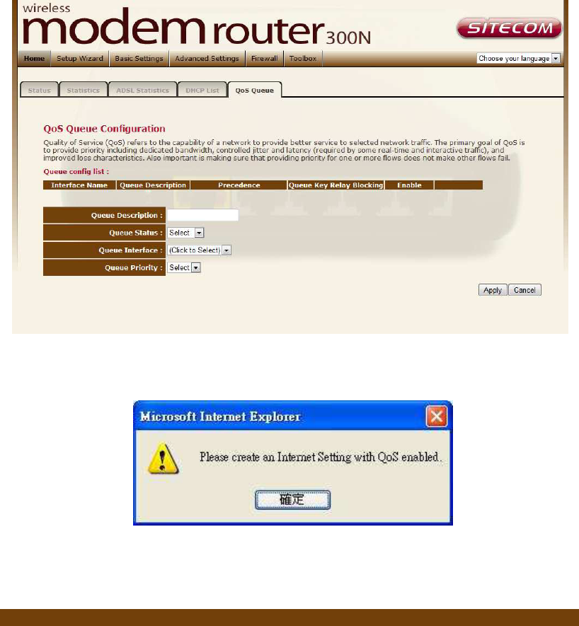
Relay Blocking When you enable this function, wireless clients will not
be able to directly access other wireless clients.
Protection
This is also called CTS Protection. It is recommended to
enable the protection mechanism. This mechanism can
decrease the rate of data collision between 802.11b
and 802.11g/802.11n wireless stations. When the
protection mode is enabled, the throughput of the AP
will be a little lower due to many of frame traffic should
be transmitted.
Aggregation This function is used to join multiple data packets for
transmission as a single unit to increase network
efficiency.
Short GI The 802.11n draft specifies two guard intervals: 400ns
(short) and 800ns (long). Support of the 400ns GI is
optional for transmit and receive. Enable this function
will increase network efficiency.
When you finish, click ‘Apply Changes’. You’ll see the following message
displayed on web browser:
Press ‘Continue’ to save the settings made and back to web management
interface; press ‘Apply’ to save the settings made and restart the router so the
settings will take effect after it reboots.
QoS
The router supports IP QoS feature that can provide different priority to
different users or data flows.
Classification
Parameter Description
IP QoS Click the radio button to enable or disable the IP QoS
function.
Default QoS Select the default mode of QoS from the list.
IP Pred:
In QoS, a three-bit field in the ToS byte of the IP header
(see RFC 791). Using IP Precedence, a network
administrator can assign values from 0(the default) to 7 to
classify and prioritize types of traffic.
802.1P:
IEEE 802.1p is a 3 bit field within an Ethernet frame
header when using tagged frames on an 802.1 network. It
specifies a priority value of between 0 and 7 inclusive that
can be used by Quality of Service (QoS) disciplines to
differentiate traffic.
Source IP The IP address of the traffic source.
Netmask (Source) The source IP netmask. This field is required if the source
IP has been entered.
Port (Source) The source port of the selected protocol. You cannot
configure this field without entering the protocol first.
Destination IP The IP address of the traffic destination.
Netmask The destination IP netmask. This field is required if the
(Destination) destination IP has been entered.
Port (Destination) The destination port of the selected protocol. You cannot
configure this field without entering the protocol first.
Protocol The selections are TCP, UDP, ICMP and the blank for none.
This field is required if the source port or destination port
has been entered.
Physical Port The incoming ports. The selections include LAN ports,
wireless port, and the blank for not applicable.
ClassQueue The priority level for the traffic that matches this
classification rule. Please refer to 5.2.5.2 QOS Queue to
create a ClassQueue.
802.1p_Mark Select this field to mark the 3-bit user-priority field in the
802.1p header of the packet that matches this
classification rule. Note that this 802.1p marking is
workable on a given PVC channel only if the VLAN tag is
enabled in this PVC channel.
IP.Pred_Mark Select this field to mark the IP precedence bits in the
packet that match this classification rule.
TOS_Mark The IP (Internet Protocol) uses the ToS (Type of Service)
field to provide an indication of the quality of service
desired. These parameters are to be used to guide the
selection of the actual service parameters when
transmitting an IP datagram through a particular
network.0
IP QoS Rules
This table lists the rules you have configured. Click “Delete
Selected” to delete the selected rules or click “Delete All”
to delete all the rules.
When you finish, click ‘Apply Changes’. You’ll see the following message
displayed on web browser:
Press ‘Continue’ to save the settings made and back to web management
interface; press ‘Apply’ to save the settings made and restart the router so the
settings will take effect after it reboots.
UPnP
When the UPnP function is enabled, the router can be detected by UPnP
compliant system such as Windows XP. The router will be displayed in the
Neighborhood of Windows XP, so you can directly double click the router or right
click the router and select “Invoke” to configure the router through web
browser.
Parameter Description
UPnP Enable or disable UPnP feature.
WAN Interface The upstream WAN interface is selected here. Select
WAN interface that will use UPnP from the drop-down
lists.
When you finish, click ‘Apply Changes’. You’ll see the following message
displayed on web browser:
Press ‘Continue’ to save the settings made and back to web management
interface; press ‘Apply’ to save the settings made and restart the router so the
settings will take effect after it reboots.
IGMP
The IGMP Proxy page allows you to enable multicast on WAN and LAN
interfaces. The LAN interface is always served as downstream IGMP proxy, and
you can configure one of the available WAN interfaces as the upstream IGMP
proxy. Upstream is the interface that IGMP requests from hosts are sent to the
multicast router. Downstream is the interface data from the multicast router are
sent to hosts in the multicast group database.
Parameter Description
IGMP Proxy Enable or disable IGMP proxy feature.
Proxy Interface The upstream WAN interface is selected here.
When you finish, click ‘Apply Changes’. You’ll see the following message
displayed on web browser:
Press ‘Continue’ to save the settings made and back to web management
interface; press ‘Apply’ to save the settings made and restart the router so the
settings will take effect after it reboots.
Routing
The page enables you to define specific route for your Internet and network
datas.
Most users do not need to define routes. On a typical small home or office LAN,
the existing routes that set up the default gateways for your LAN hosts and for
the router provide the most appropriate path for all your Internet traffic.
You may need to define routes if your home setup includes two or more
networks or subnets, if you connect to two or more ISP services, or if you
connect to a remote corporate LAN.
Parameter Description
Enable Check to enable the selected route or route to be added.
Destination The destination can be specified as the IP address of a
subnet or a specific host in the subnet. It can also be
specified as all zeros to indicate that this route should be
used for all destinations for which no other route is
defined (this is the route that creates the default
gateway).
Subnet Mask The network mask of the destination subnet. The default
gateway uses a mask of 0.0.0.0.
Next Hop The IP address of the next hop through which traffic will
flow towards the destination subnet.
Metric Defines the number of hops between network nodes that
data packets travel. The default value is 0, which means
that the subnet is directly one hop away on the local LAN
network.
Interface The WAN interface to which a static routing subnet is to
be applied.
Add Route Add a user-defined destination route.
Show Routes Click this button to view the router’s routing table.
Static Route
Table
Click “Update” to update the selected destination route o
n
the “Static Route Table”. Click “Delete Selected” to delete
a selected destination route on the Static Route Table.
When you finish, click ‘Apply Changes’. You’ll see the following message
displayed on web browser:
Press ‘Continue’ to save the settings made and back to web management
interface; press ‘Apply’ to save the settings made and restart the router so the
settings will take effect after it reboots.
SNMP
Simple Network Management Protocol (SNMP) is a troubleshooting and
management protocol that uses the UDP protocol on port 161 to communicate
between clients and servers. The router can be managed locally or remotely by
SNMP protocol.
Parameter Description
SNMP Select “Disable” or “Enable” to disable or enable the
SNMP feature.
System Description
Enter the system description of the router.
System Contact Enter the contact person and/or contact information
for the router.
System Name Assign an administratively name for the router.
System Location The physical location of the router.
System Object ID It is the vendor object identifier. The vendor’s
authoritative identification of the network
management subsystem contained in the entity.
Trap IP Address Destination IP address of the SNMP trap.
Community name
(read-only)
Name of the read-only community. This read-only
community allows read operation to all objects in the
MIB.
Community name
(write-only)
Name of the write-only community. This write-only
community allows write operation to the objects
defines as read-writable in the MIB.
When you finish, click ‘Apply Changes’. You’ll see the following message
displayed on web browser:
Press ‘Continue’ to save the settings made and back to web management
interface; press ‘Apply’ to save the settings made and restart the router so the
settings will take effect after it reboots.
DDNS
Dynamic DNS (DDNS) allows you to map the static domain name to a dynamic
IP address. You must get an account, password and your static domain name
from the DDNS service providers.
Parameter Description
Enable Check the box to enable DDNS function.
DDNS Provider Select your DDNS service provider here. This router
supports DynDNS and TZO service providers
Host Name Enter the domain name you’ve obtained from DDNS
service provider.
DynDns Settings
Username Enter the username assigned by the DDNS service
provider.
Password Enter the password assigned by the DDNS service
provider.
TZO Settings
Email Enter the Email account that your DDNS service
provider assigned to you.
Key Enter the
password that your DDNS service provider
assigned to you.
Add/Modify/Remove
These buttons are for you to maintain the DDNS
table.-
Dynamic DDNS Table
The DDNS you have configured will be added to the
list.
When you finish, click ‘Apply Changes’. You’ll see the following message
displayed on web browser:
Press ‘Continue’ to save the settings made and back to web management
interface; press ‘Apply’ to save the settings made and restart the router so the
settings will take effect after it reboots.
RIP
RIP is an Internet protocol you can set up to share routing table information
with other routing devices on your LAN, at your ISP’s location, or on remote
networks connected to your network via the ADSL line.
Most small home or office networks do not need to use RIP; they have only
one router, such as the ADSL Router, and one path to an ISP. In these cases,
there is no need to share routes, because all Internet data from the network is
sent to the same ISP gateway.
You may want to configure RIP if any of the following circumstances apply to
your network:
Your home network setup includes an additional router or RIP-enabled PC
(other than the ADSL Router). The ADSL Router and the router will need to
communicate via RIP to share their routing tables.
Your network connects via the ADSL line to a remote network, such as a
corporate network. In order for your LAN to learn the routes used within your
corporate network, they should both be configured with RIP.
Your ISP requests that you run RIP for communication with devices on their
network.
Parameter Description
RIP Enable/disable the RIP feature.
Interface Select the interface that you want to enable the RIP
feature.
Receive Mode Indicate the RIP version in which information must be
passed to the DSL device in order for it to be
accepted into its routing table.
Send Mode Indicate the RIP version this interface will use when it
sends its route information to other devices.
RIP Config Table
The RIP you have configured will be listed in the t
able.
If you want to delete some settings, please select the
settings and click “Delete Selected.
When you finish, clickApply Changes’. You’ll see the following message
displayed on web browser:
Press ‘Continue’ to save the settings made and back to web management
interface; press ‘Apply’ to save the settings made and restart the router so the
settings will take effect after it reboots.
13 Firewall Settings
The Broadband router provides extensive firewall protection by restricting
connection parameters, thus limiting the risk of hacker attacks, and defending
against a wide array of common Internet attacks. However, for applications that
require unrestricted access to the Internet, you can configure a specific
client/server as a Demilitarized Zone (DMZ).
Port Forwarding
The Port Forwarding allows you to re-direct a particular range of service port
numbers (from the Internet) to a particular LAN IP address. It helps you to host
some servers behind the router NAT firewall.
Parameter Description
Port Forwarding Check this item to enable or disable the port-forwarding
feature.
Protocol
This is the protocol type to be forwarded. You can choose
to forward “TCP” or “UDP” packets only or select “Both”
to forward both “TCP” and “UDP” packets.
Comment Enter the comment for the setting.
Enable Check this item to enable this entry.
Local IP Address IP address of your local server that will be accessed by
Internet.
Local IP Port The destination port number that is made open for this
application on the LAN side.
Remote IP Address
The source IP address from which the incoming traffic is
allowed. Leave blank for all.
Public Port The destination port number that is made open for this
application on the WAN side
Interface Select the WAN interface on which the port-forwarding
rule is to be applied.
Current Port
Forwarding Table
If you want to remove the port forwarding settings from
the table, select the items and then click "Delete
Selected". If you want remove all settings, just click
"Delete All" button.
When you finish, click ‘Apply Changes’. You’ll see the following message
displayed on web browser:
Press ‘Continue’ to save the settings made and back to web management
interface; press ‘Apply’ to save the settings made and restart the router so the
settings will take effect after it reboots.
Port Filter
The IP/Port filtering feature allows you to deny/allow specific services or
applications in the forwarding path.
Parameter Description
Outgoing Default
Action
Specify the default action on the LAN to WAN (Traffic to
Internet) forwarding path. You can choose ‘Allow’ if you
allow the IP Addresses listed in the following table to
connect to the Internet; choose ‘Deny’ if you deny the
IP Addressed listed in the following table to connect to
the Internet.
Incoming Default
Action
Specify the default action on the WAN to LAN (Traffic
from Internet) forwarding path. You can choose ‘Allow’
if you allow the IP Addresses listed in the following
table from connecting to the Internet; choose ‘Deny’ if
you deny the IP Addressed listed in the following table
from connecting to the Internet.
Direction Select the traffic forwarding direction: outgoing or
incoming.
Protocol There are 3 options available: TCP, UDP and ICMP.
Rule Action Deny or allow traffic when matching this rule.
Source IP Address
Enter the start IP Address which will be monitored.
Subnet Mask Enter the Subnet Mask based on the Source IP
Address.
Port LAN users use port number to distinguish one network
application over another such as 21 is for FTP service.
The port number range is from 0 to 65535. It is
recommended that this option be configured by an
advanced user.
Destination IP
Address
Enter the destination IP Address which will be
monitored.
Subnet Mask Enter the Subnet Mask based on the Destination IP
Address.
Port This is the port or port ranges that define the
application.
Current Filter
Table
If you want to remove some IP/Port filter settings from
the "Current Filter Table", select the items you want to
remove in the list and then click "Delete Selected". If
you want remove all the items from the table, just click
"Delete All" button.
When you finish, click ‘Apply Changes’. You’ll see the following message
displayed on web browser:
Press ‘Continue’ to save the settings made and back to web management
interface; press ‘Apply’ to save the settings made and restart the router so the
settings will take effect after it reboots.
MAC Filtering
The MAC filtering feature allows you to define rules to allow or deny frames
through the router based on source MAC address, destination MAC address, and
traffic direction.
Parameter Description
Outgoing Default
Action
Specify the default action on the LAN to WAN (Traffic to
Internet) forwarding path. You can choose ‘Allow’ if you
allow the IP Addresses listed in the following table from
connecting to the Internet; choose ‘Deny’ if you deny
the IP Addressed listed in the following table from
connecting to the Internet.
Incoming Default
Action
Specify the default action on the WAN to LAN (Traffic
from Internet) forwarding path. You can choose ‘Allow’
if you allow the IP Addresses listed in the following
table from connecting to the Internet; choose ‘Deny’ if
you deny the IP Addressed listed in the following table
from connecting to the Internet.
Direction Traffic bridging/forwarding direction: outgoing or
incoming.
Rule Action Deny or allow traffic when matching this rule.
Source MAC
Address
The source MAC address. It must be 12-digit
hexadecimal format, for example: “00-d0-59-c6-12-
43”.
Destination MAC
Address
The destination MAC address. It must be 12-digit
hexadecimal format, for example: “00-d0-59-c6-12-
50”.
Current Filter
Table
If you want to remove some filter rules from the
"Current Filter Table", select the MAC Address you want
to remove in the table and then click "Delete Selected".
If you want remove all settings from the table, just
click "Delete All" button.
When you finish, click ‘Apply Changes’. You’ll see the following message
displayed on web browser:
Press ‘Continue’ to save the settings made and back to web management
interface; press ‘Apply’ to save the settings made and restart the router so the
settings will take effect after it reboots.
URL Blocking
This page is used to block some URL addresses or keywords.
Parameter Description
URL Blocking Enable or disable the URL blocking function.
FQDN Enter FQDN which you want to block. A FQDN is a
complete DNS name. For example, “www.yahoo.com”.
URL Blocking Table
The FQDN settings will be listed in the table. If you
want to delete some FQDN settings from the table,
please select the settings and click “Delete Selected.
If you want remove all settings from the table, just
click "Delete All" button.
Keyword Enter the keyword of the URL Address that you want to
filter.
Keyword Filtering
Table
The keyword settings will be listed in the table. If you
want to delete some keyword settings from the table,
please select the settings and click “Delete Selected.
If you want remove all settings from the table, just
click "Delete All" button.
When you finish, click ‘Apply Changes’. You’ll see the following message
displayed on web browser:
Press ‘Continue’ to save the settings made and back to web management
interface; press ‘Apply’ to save the settings made and restart the router so the
settings will take effect after it reboots.
Domain Blocking
The firewall includes the ability to block access to specific domain based on
string matches. For example, if the URL of Taiwan Yahoo web site is
“tw.yahoo.com” and you enter “yahoo.com”, the firewall will block all the DNS
queries with “yahoo.com” string. So the Host will be blocked to access all the
URLs belong to “yahoo.com” domain. That means you can protect your
computer, your house, your office and anything else that uses DNS from being
able to service domains that you don’t want to load.
Parameter Description
Domain Blocking Check this item to enable the Domain Blocking feature.
Domain The blocked domain. If the URL of Taiwan Yahoo web
site is tw.yahoo.com, the domain can be yahoo.com.
Delete Selected/All
If you want to delete a specific Domain Block entry,
check the ‘select’ box of the Domain Block you want to
delete, then click ‘Delete Selected’ button. If you want
remove all settings from the table, just click "Delete
All" button.
ACL Configuration
The Access Control List (ACL) is a list of permissions attached to the router. The
list specifies who is allowed to access this router. If ACL is enabled, all hosts
cannot access this router except for the hosts with IP address in the ACL table.
Parameter Description
ACL Capability
Enable or disable the ACL function
Enable Check to enable this ACL entry
Interface Select the interface domain: LAN or WAN
IP Address Enter the IP address that is allowed to access the router.
Subnet Mask Enter the Subnet Mask that is allowed to access the router.
ACL Table The ACL settings will be listed here. You can click “Delete
Selected” to delete the settings you have selected. If you
want remove all settings from the table, just click "Delete
All" button.
When you finish, click ‘Apply Changes’. You’ll see the following message
displayed on web browser:
Press ‘Continue’ to save the settings made and back to web management
interface; press ‘Apply’ to save the settings made and restart the router so the
settings will take effect after it reboots.
DMZ
The DMZ Host is a local computer exposed to the Internet. When setting a
particular internal IP Address as the DMZ Host, all incoming packets will be
checked by the firewall and NAT algorithms then passed to the DMZ Host.
For example, if you have a local client PC that cannot run an Internet
application (e.g. Games) properly from behind the NAT firewall, then you can
open the client up to unrestricted two-way Internet access by defining a DMZ
Host.
Parameter Description
DMZ Host Check the item to enable the DMZ function.
DMZ Host IP
Address
Enter a static IP Address to the DMZ Host. This IP
Address will be exposed to the Internet.
When you finish, click ‘Apply Changes’. You’ll see the following message
displayed on web browser:
Press ‘Continue’ to save the settings made and back to web management
interface; press ‘Apply’ to save the settings made and restart the router so the
settings will take effect after it reboots.
14 TOOLBOX Settings
Password
This page allows you to set the password to access the web server of the router.
Please select the “admin (as administrator)” or “user (as user)” account and
configure the password.
When you finish, click ‘Apply Changes’.
If the password you typed in ‘New Password’ and ‘Confirmed Password’ field are
not the same, you’ll see the following message:
Please retype the new password again when you see above message.
If you see the following message:
It means the content in ‘Current Password’ field is wrong, please click ‘OK’ to go
back to previous menu, and try to input current password again.
If the current and new passwords are correctly entered, after you click ‘Apply’,
you’ll be prompted to input your new password:
Please use new password to enter web management interface again, and you
should be able to login with new password.
Time Zone
The Time Zone allows your router to set its time; especially for recording
System Log.
Parameter Description
Current Time
The current time of the specified time zone. You can set
the current time by yourself or configured by SNTP
server.
Time Zone Select Select the time zone of the country you are currently
in. The router will set its time based on your selection.
Enable SNTP client
update
Check the box to enable router to update time from
SNTP server.
SNTP server The IP address or the host name of the SNTP server.
You can select from the list or set it manually.
When you finish, click ‘Apply Changes’. You’ll see the following message
displayed on web browser:
Press ‘Continue’ to save the settings made and back to web management
interface; press ‘Apply’ to save the settings and restart the router so the
settings will take effect after it reboots.
Remote Access
The Remote Access function can secure remote host access to your router from
LAN and WAN interfaces for some services provided by the router. These
services include Telnet, FTP, TFTP, HTTP, SNMP and PING.
Please click ‘System’ menu on the left of web management interface, then click
‘Remote Management’, and the following page will be displayed on your web
browser:
Parameter Description
LAN Check/un-check the services on the LAN column to allow/un-
allow the services access from LAN side.
WAN Check/un-check the services on the WAN column to allow/un-
allow the services access from WAN side.
WAN Port This field allows the user to specify the port of the
corresponding to the service. Take the HTTP service for
example; when it is changed to 8080, the HTTP server address
for the WAN side is http://dsl_addr:8080, where the “dsl addr
is the WAN side IP address of the router.
When you finish, click ‘Apply Changes’. You’ll see the following message
displayed on web browser:
Press ‘Continue’ to save the settings made and back to web management
interface; press ‘Apply’ to save the settings made and restart the router so the
settings will take effect after it reboots.
Firmware Upgrade
This page allows you to upgrade the firmware for the router. Click “Browse”
button to select the firmware file and click “Upload” button to start upgrading.
IMPORTANT! Do not turn off your router while this procedure is in progress.
Configuration Tools
This page allows you to backup the current settings to a file or restore the
settings from the file which was saved previously. Besides, you could reset the
current configuration to factory defaults.
Parameter Description
Save Settings to
File
Click Save button to save the ADSL router current
configuration to a file named "config.bin" on your PC.
Load Settings from
File
Click Browse button to search the file you have saved
before and click Upload button to restore the saved
configuration to the ADSL router.
Restore Settings to
Default
Click Reset button if you want to force the ADSL router
to perform a power reset and restore the original
factory settings.
Reboot
Whenever you use the Web configuration to change system settings, the
changes are initially placed in temporary storage. To save your change for
future use, you have to click “Apply” to reboot the router. If you have
encountered problems during the configuration, You can click the “OPS” button
in the top panel of the router over 15 seconds to reset default settings.
Diagnostics
Ping
Once you have your router configured, you can send a ping command to the
host you specify in this page. To use it, you must know the IP address of the
host you are trying to communicate with and enter the IP address in the Host
Address field.
ATM Loopback
In order to isolate the ATM interface problems, you can use ATM OAM loopback
cells to verify connectivity between VP/VC endpoints, as well as segment
endpoints within the VP/VC. This page allows you to use ATM ping to test the
reachable of a segment endpoint or a connection endpoint.
Parameter Description
Select PVC Select the PVC channel you want to do the loop-back diagnostic.
Flow Type The ATM OAM flow type. The selection can be F5 Segment or F5
End-to-End. ATM uses F4 and F5 cell flows as follows:
F4: used in VPs
F5: used in VCs
Loopback
Location ID
The loop-back location ID field of the loop-back cell. The default
value is all 1s (ones) to indicate the endpoint of the segment or
connection.
Click “Start test” to save the setting to the configuration.
Diagnostic Test
The Diagnostic Test page shows the test results for the connectivity of the
physical layer and protocol layer for both LAN and WAN sides.
20

Hulp nodig? Stel uw vraag in het forum

Spelregels

Misbruik melden

Gebruikershandleiding.com neemt misbruik van zijn services uitermate serieus. U kunt hieronder aangeven waarom deze vraag ongepast is. Wij controleren de vraag en zonodig wordt deze verwijderd.

Product:

Bijvoorbeeld antisemitische inhoud, racistische inhoud, of materiaal dat gewelddadige fysieke handelingen tot gevolg kan hebben.

Bijvoorbeeld een creditcardnummer, een persoonlijk identificatienummer, of een geheim adres. E-mailadressen en volledige namen worden niet als privégegevens beschouwd.

Spelregels forum

Om tot zinvolle vragen te komen hanteren wij de volgende spelregels:

Belangrijk! Als er een antwoord wordt gegeven op uw vraag, dan is het voor de gever van het antwoord nuttig om te weten als u er wel (of niet) mee geholpen bent! Wij vragen u dus ook te reageren op een antwoord.

Belangrijk! Antwoorden worden ook per e-mail naar abonnees gestuurd. Laat uw emailadres achter op deze site, zodat u op de hoogte blijft. U krijgt dan ook andere vragen en antwoorden te zien.

Abonneren

Abonneer u voor het ontvangen van emails voor uw Sitecom WLM-1500 - N300 X2 bij:


U ontvangt een email met instructies om u voor één of beide opties in te schrijven.


Ontvang uw handleiding per email

Vul uw emailadres in en ontvang de handleiding van Sitecom WLM-1500 - N300 X2 in de taal/talen: Engels als bijlage per email.

De handleiding is 2,66 mb groot.


U ontvangt de handleiding per email binnen enkele minuten. Als u geen email heeft ontvangen, dan heeft u waarschijnlijk een verkeerd emailadres ingevuld of is uw mailbox te vol. Daarnaast kan het zijn dat uw internetprovider een maximum heeft aan de grootte per email. Omdat hier een handleiding wordt meegestuurd, kan het voorkomen dat de email groter is dan toegestaan bij uw provider.

Stel vragen via chat aan uw handleiding

Stel uw vraag over deze PDF

Uw handleiding is per email verstuurd. Controleer uw email

Als u niet binnen een kwartier uw email met handleiding ontvangen heeft, kan het zijn dat u een verkeerd emailadres heeft ingevuld of dat uw emailprovider een maximum grootte per email heeft ingesteld die kleiner is dan de grootte van de handleiding.

Er is een email naar u verstuurd om uw inschrijving definitief te maken.

Controleer uw email en volg de aanwijzingen op om uw inschrijving definitief te maken

U heeft geen emailadres opgegeven

Als u de handleiding per email wilt ontvangen, vul dan een geldig emailadres in.

Uw vraag is op deze pagina toegevoegd

Wilt u een email ontvangen bij een antwoord en/of nieuwe vragen? Vul dan hier uw emailadres in.


Info