Table of Contents
1. Introduction.....................................................................................................4
Overview..........................................................................................................4
Features.....................................................................................................4
Internet Features.........................................................................................5
Security Features.........................................................................................5
Wireless Features (WL-404 only)....................................................................5
Physical Details.................................................................................................6
Front - Network Camera...............................................................................6
Rear - Network Camera................................................................................7
Package Contents........................................................................................8
2. Basic Setup.......................................................................................................9
System Requirements........................................................................................9
Installation - Network Camera.............................................................................9
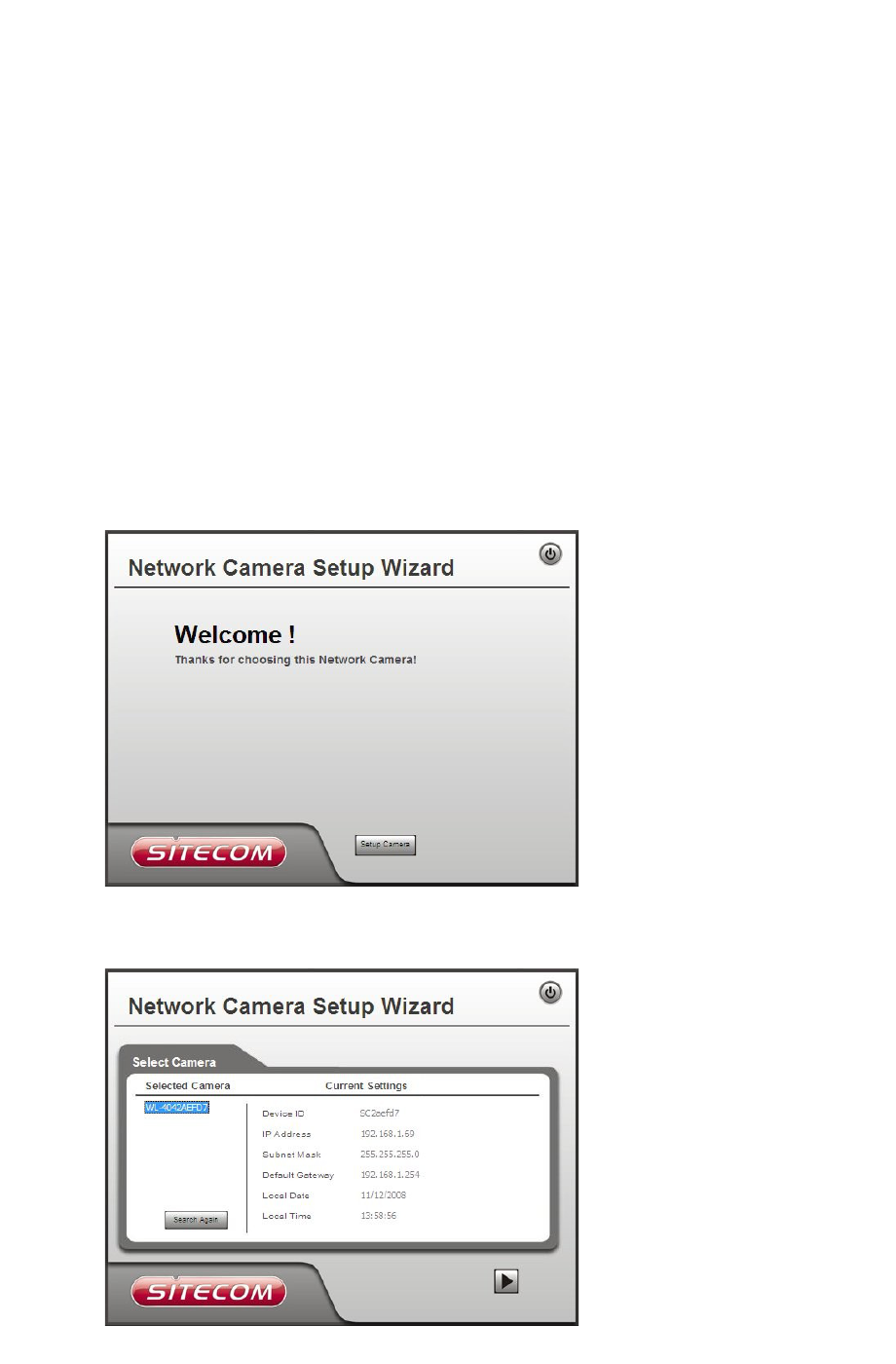
Setup using the Windows Wizard.......................................................................10
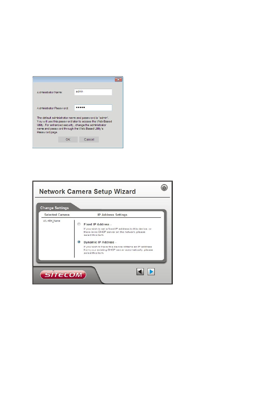
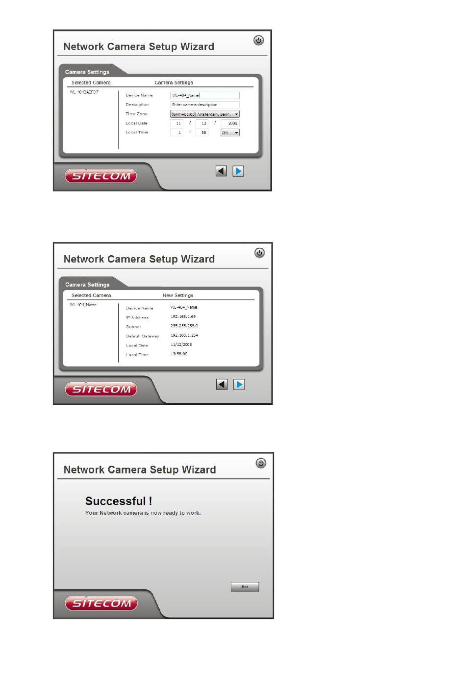
Setup Procedure........................................................................................10
3. Viewing Live Video..........................................................................................13
Overview........................................................................................................13
Requirements..................................................................................................13
Connecting to a Camera on your LAN.................................................................13
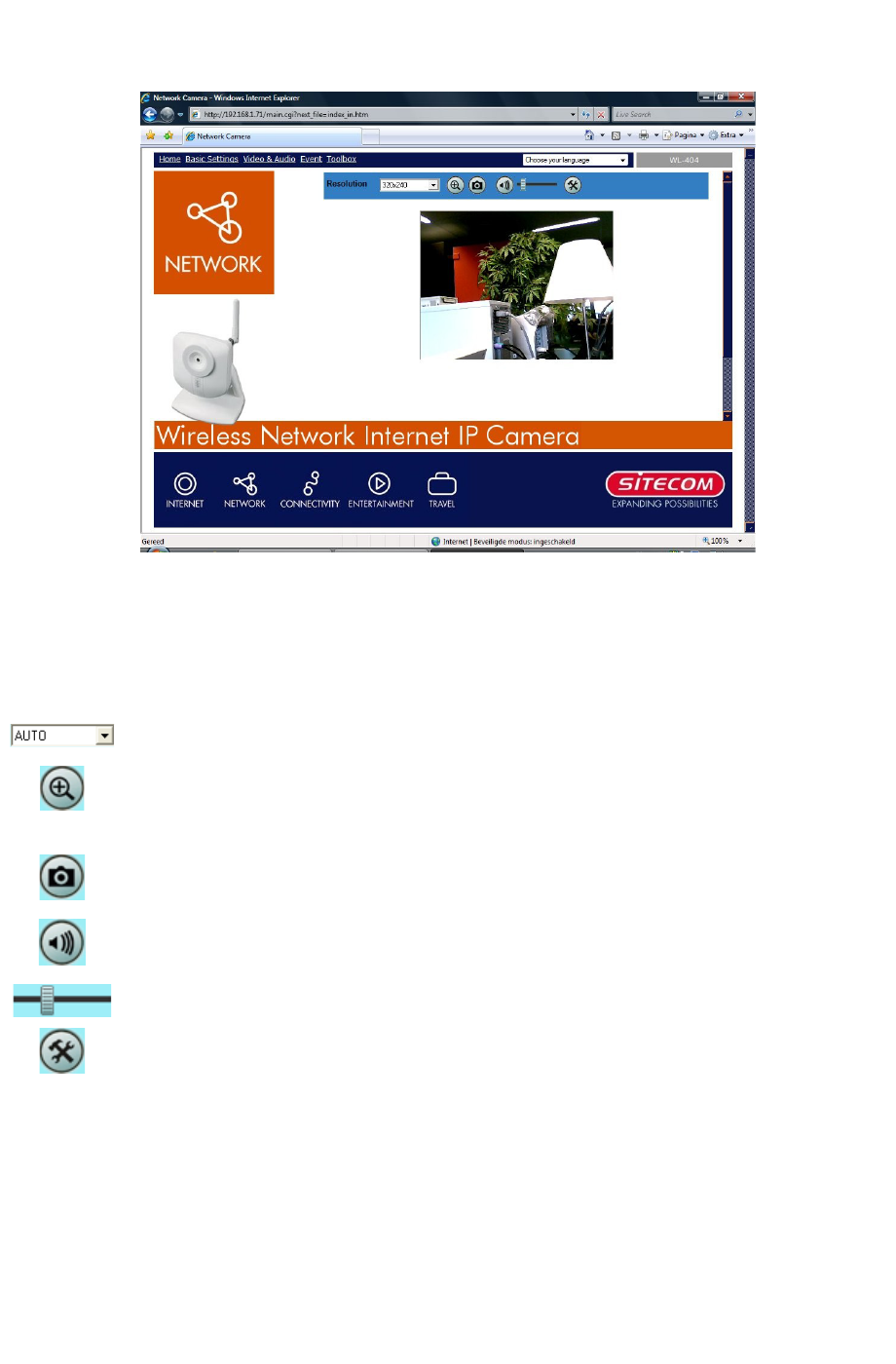
Viewing Live Video...........................................................................................15
General Options.........................................................................................15
4. Advanced Viewing Setup................................................................................16
Introduction....................................................................................................16
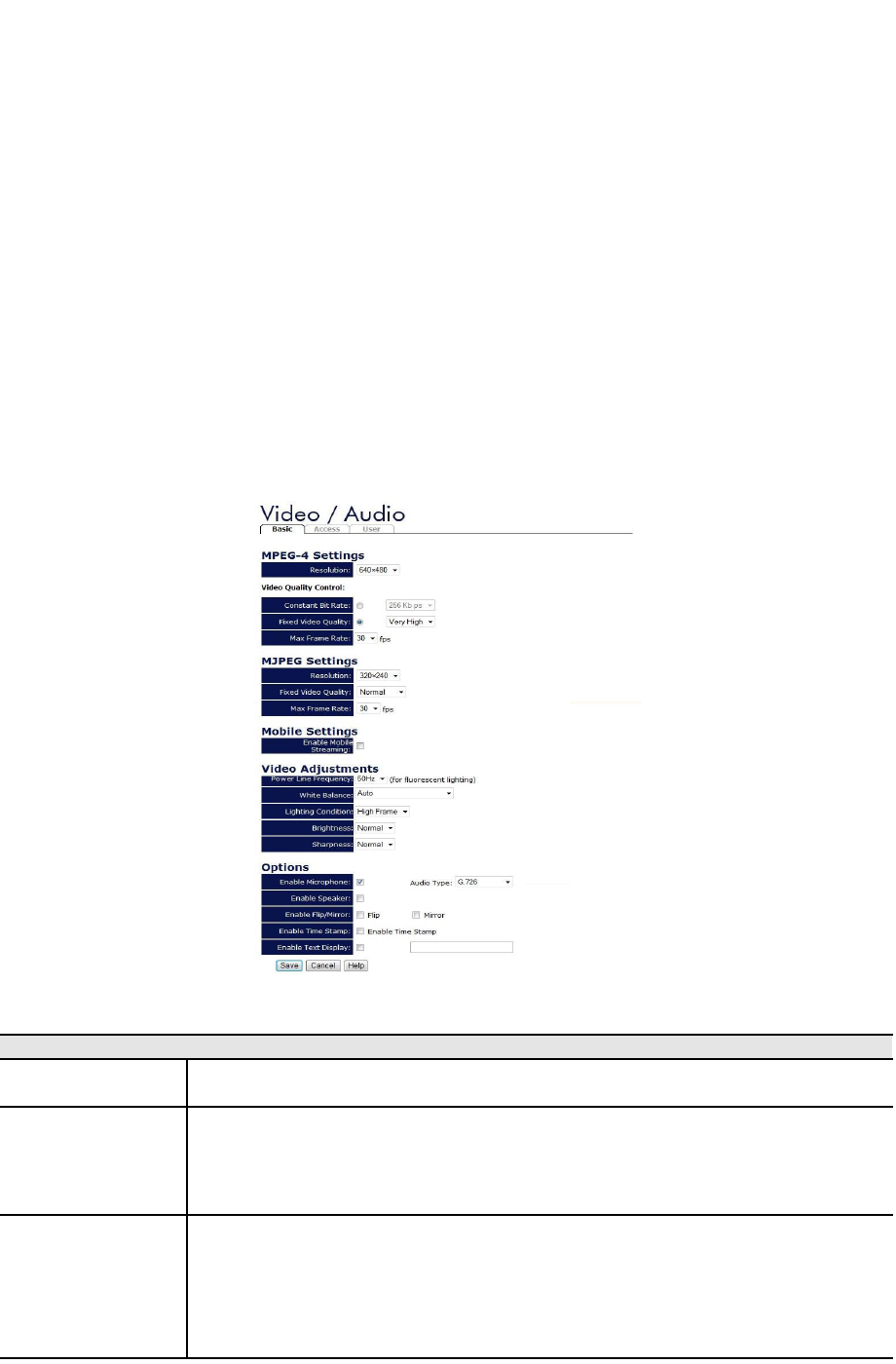
Adjusting the Video Image................................................................................16
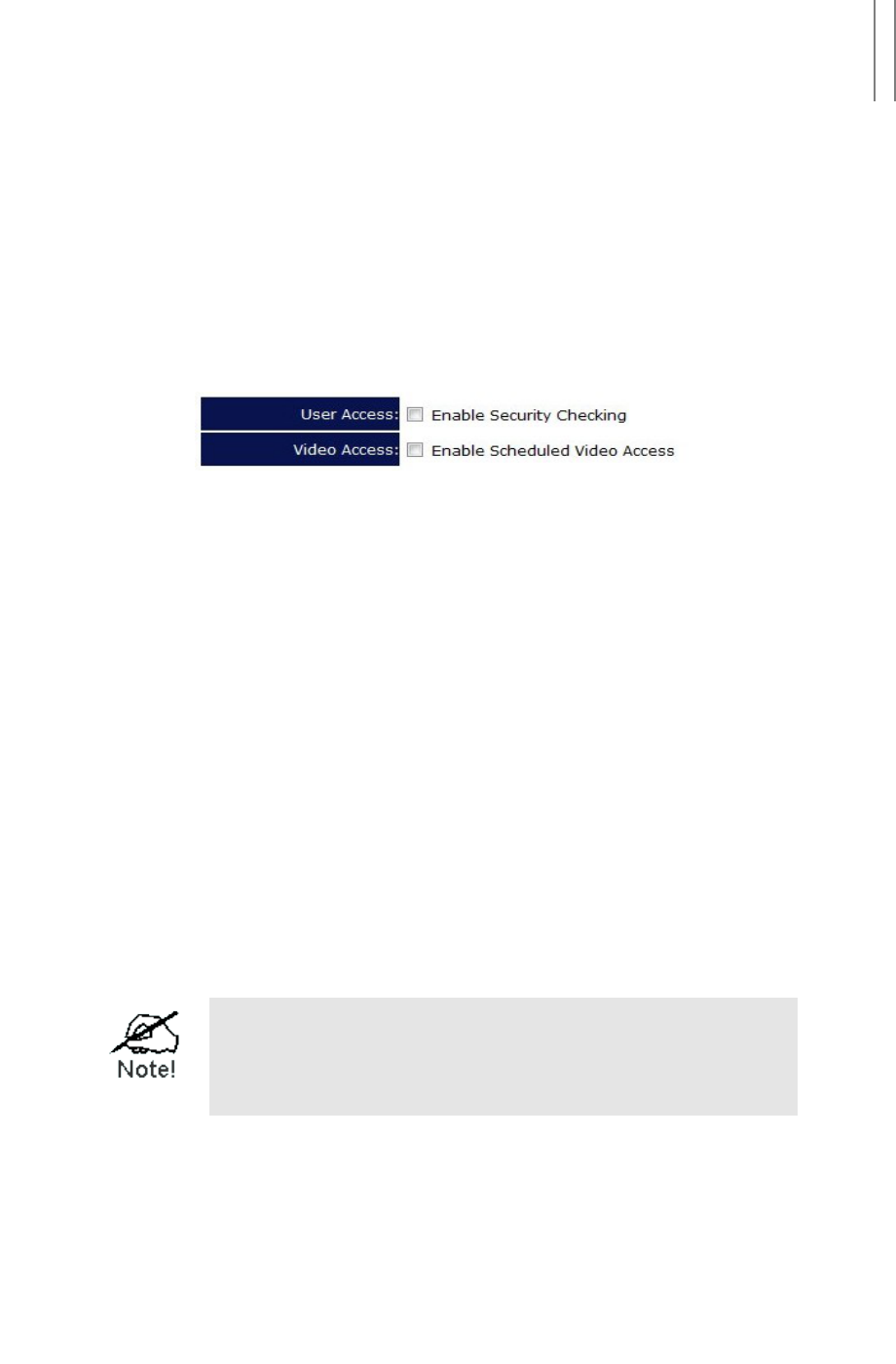
Controlling User Access to the Video Stream.......................................................18
Making Video available from the Internet............................................................18
Router/Gateway Setup................................................................................18
Network Camera Setup...............................................................................18
HTTP Port Configuration..............................................................................19
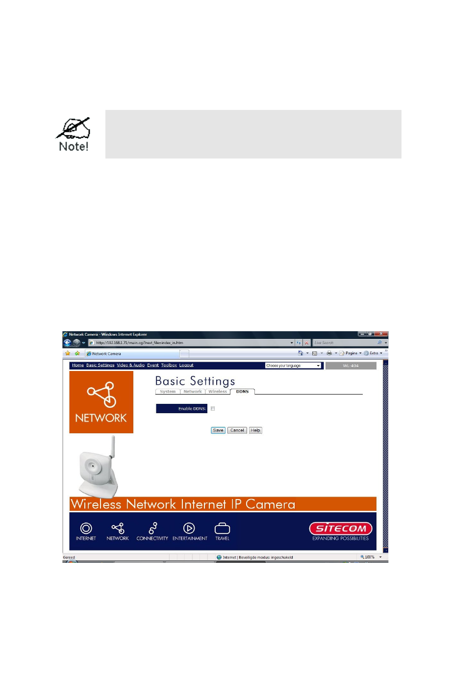
DDNS (Dynamic DNS).................................................................................19
To use DDNS:............................................................................................19
Viewing Live Video via the Internet....................................................................20
Viewing Live Video Using your Web Browser..................................................20
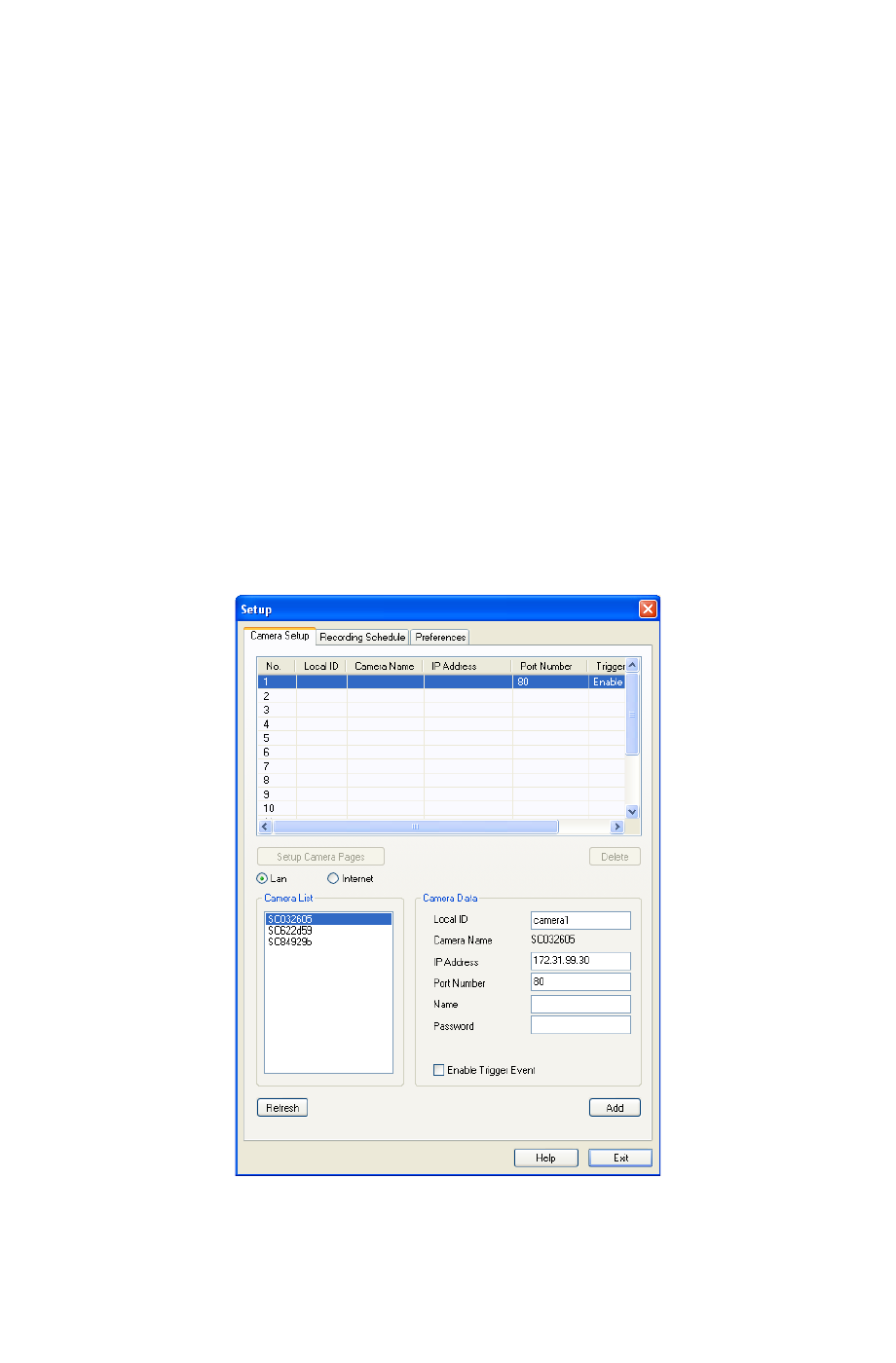
Viewing Live Video with the Viewing/Recording Utility.....................................20
Motion Detection Alerts.....................................................................................21
To Use Motion Detection Alerts.....................................................................21
5. Web-based Management................................................................................22
Introduction....................................................................................................22
Connecting to Network Camera.........................................................................22
Connecting using your Web Browser.............................................................22
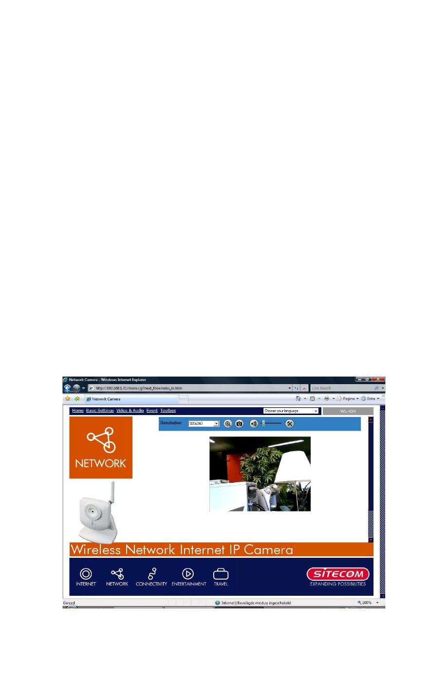
Welcome Screen..............................................................................................22
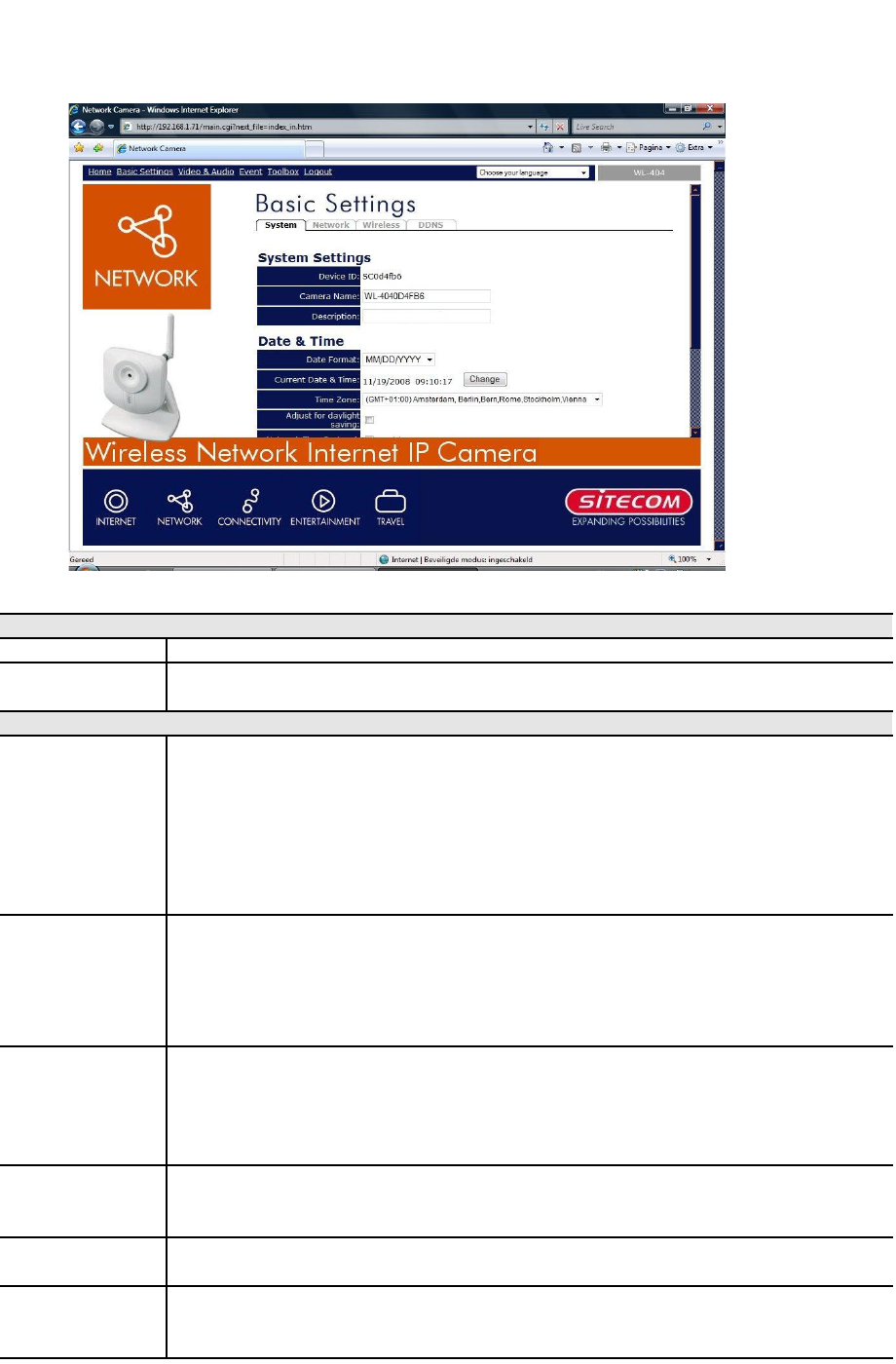
Basic Settings – System...................................................................................23
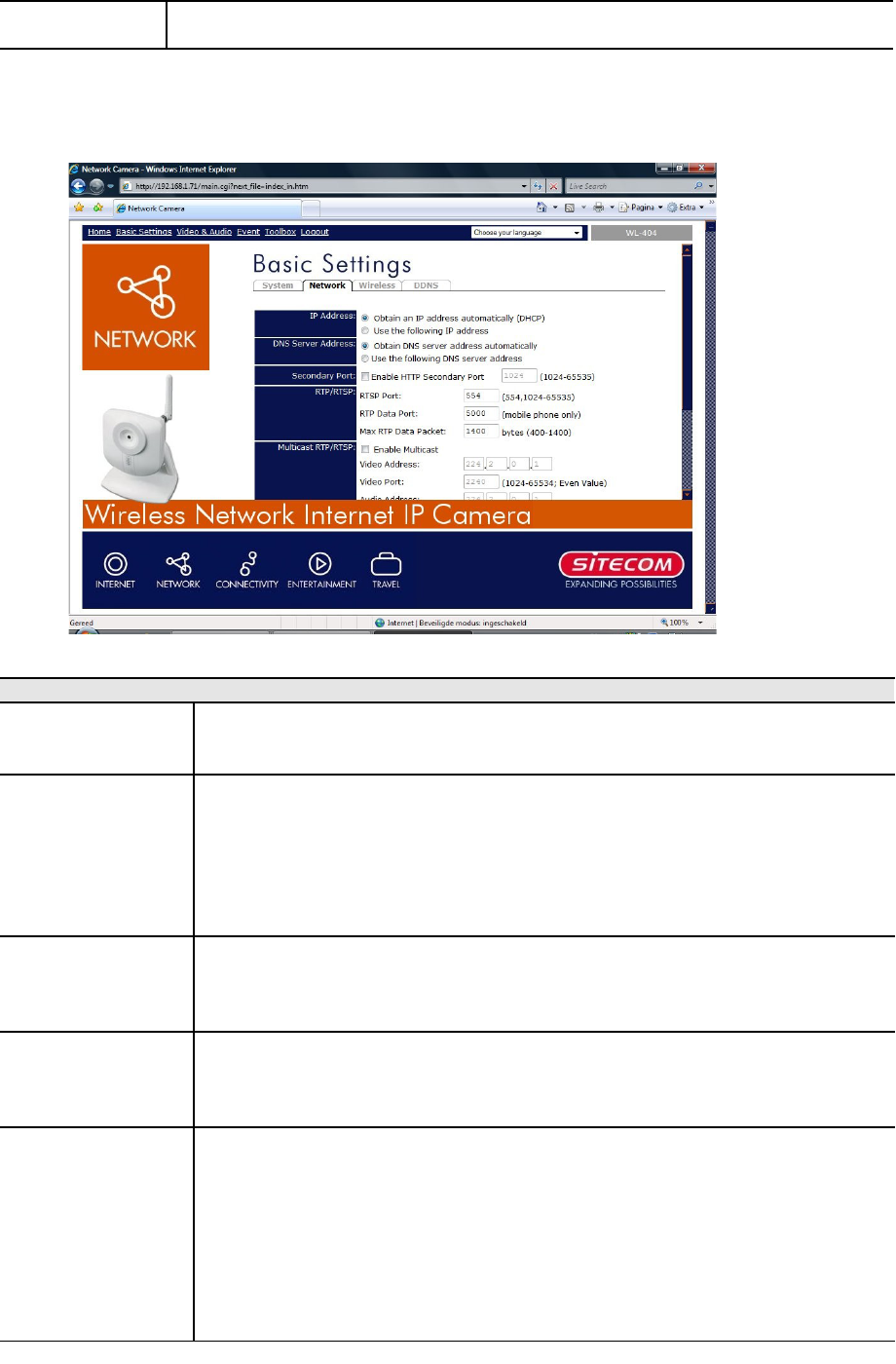
Basic Settings - Network...................................................................................24
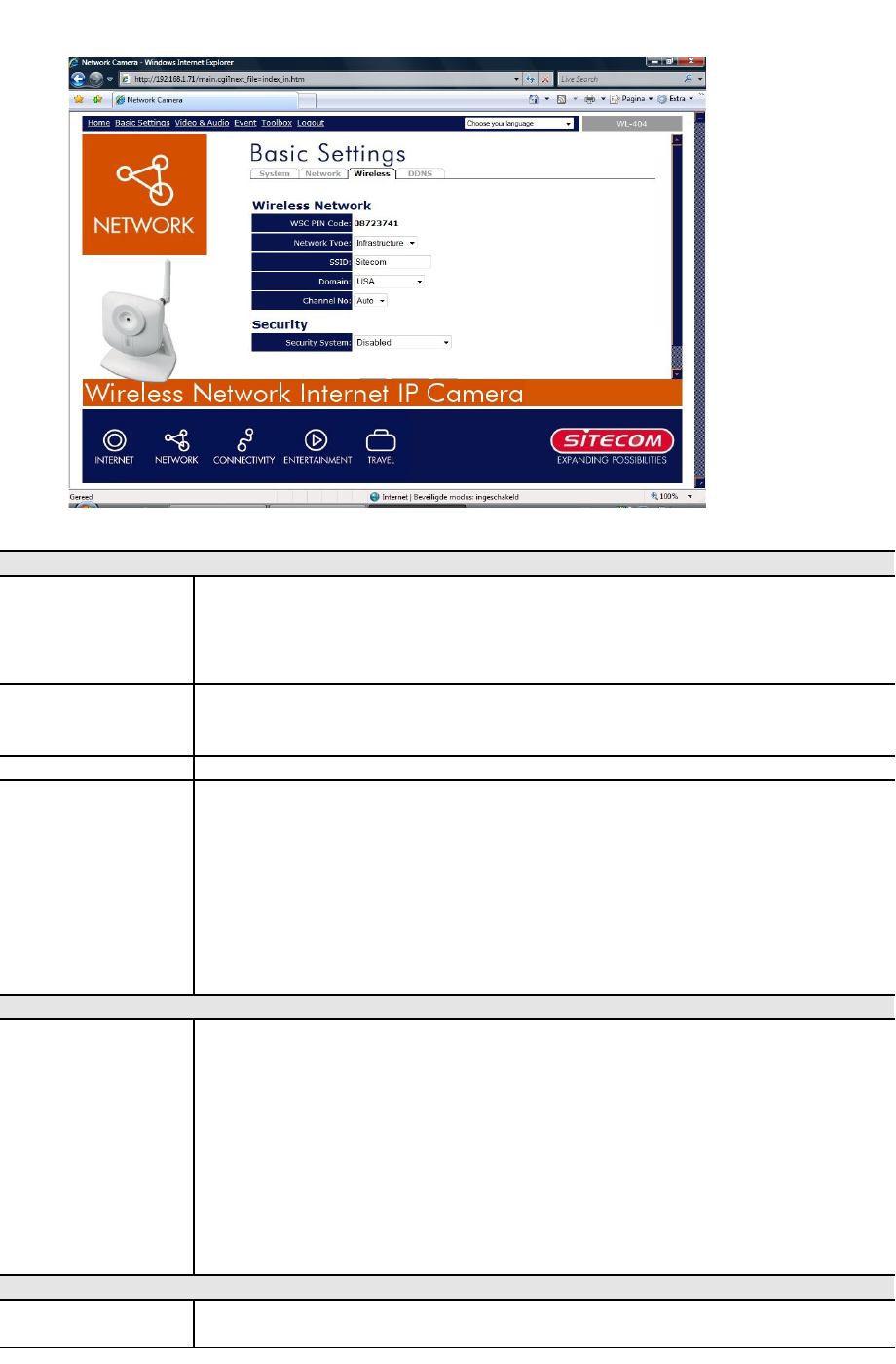
Basic Settings - Wireless (WL-404 only)..............................................................26
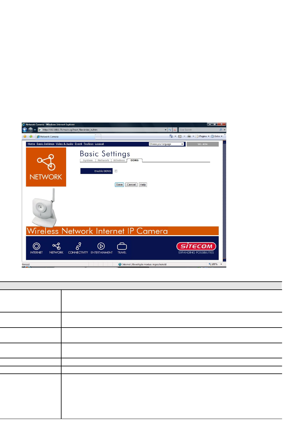
Basic Settings - DDNS......................................................................................28
Video & Audio - Basic.......................................................................................29
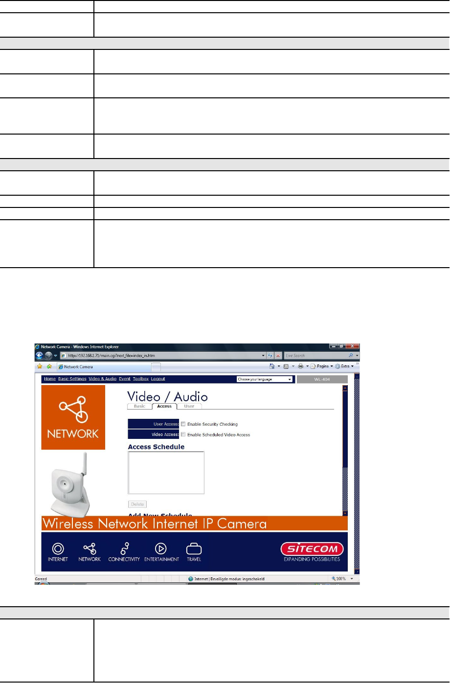
Video & Audio - Access.....................................................................................30
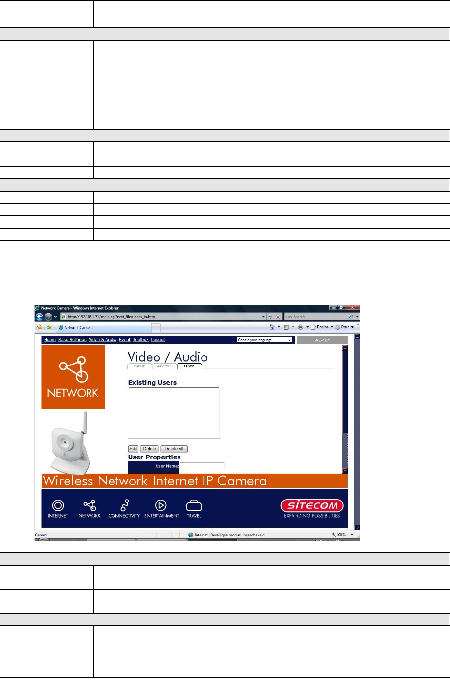
Video & Audio - User........................................................................................31
User List................................................................................................31
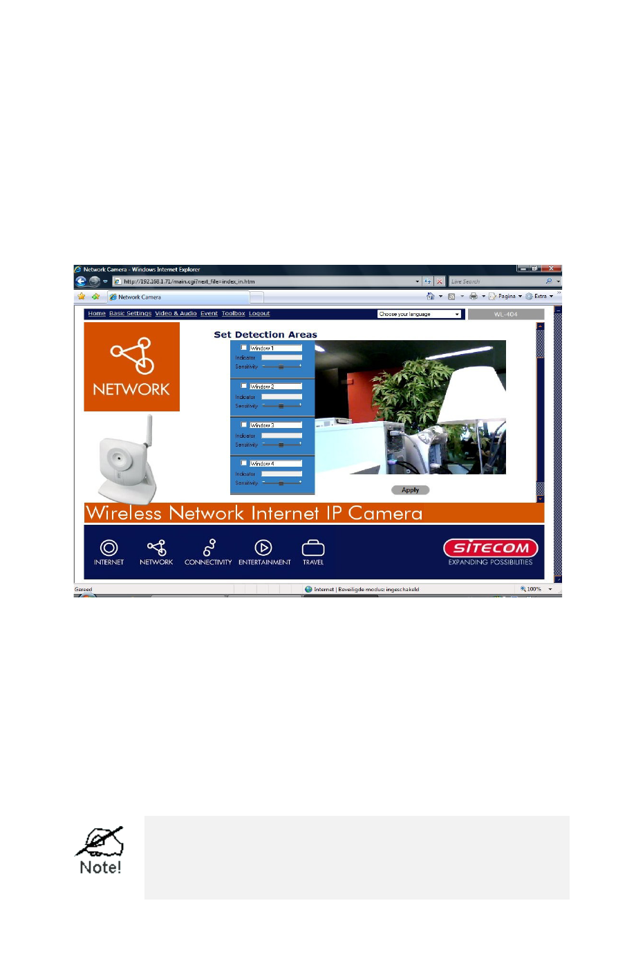
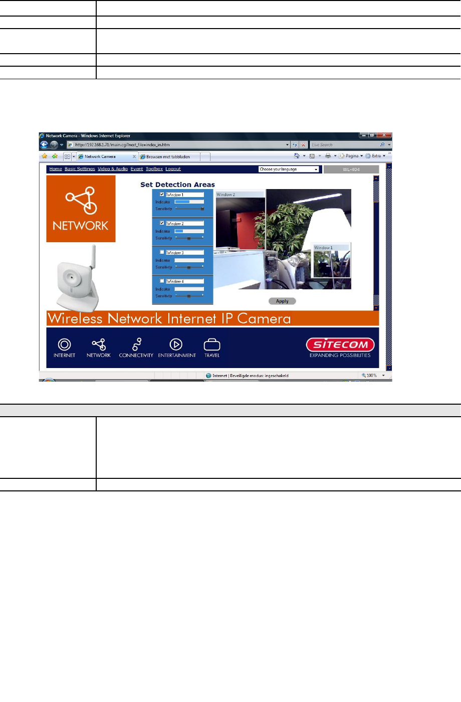
Event - Motion Detection..................................................................................32
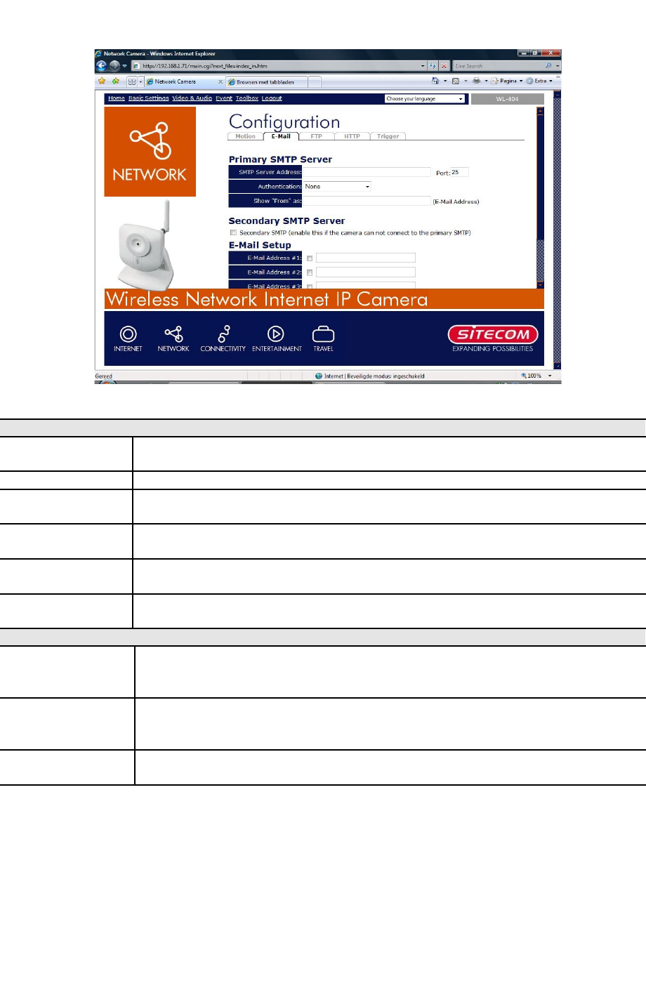
Event - E-Mail.................................................................................................33
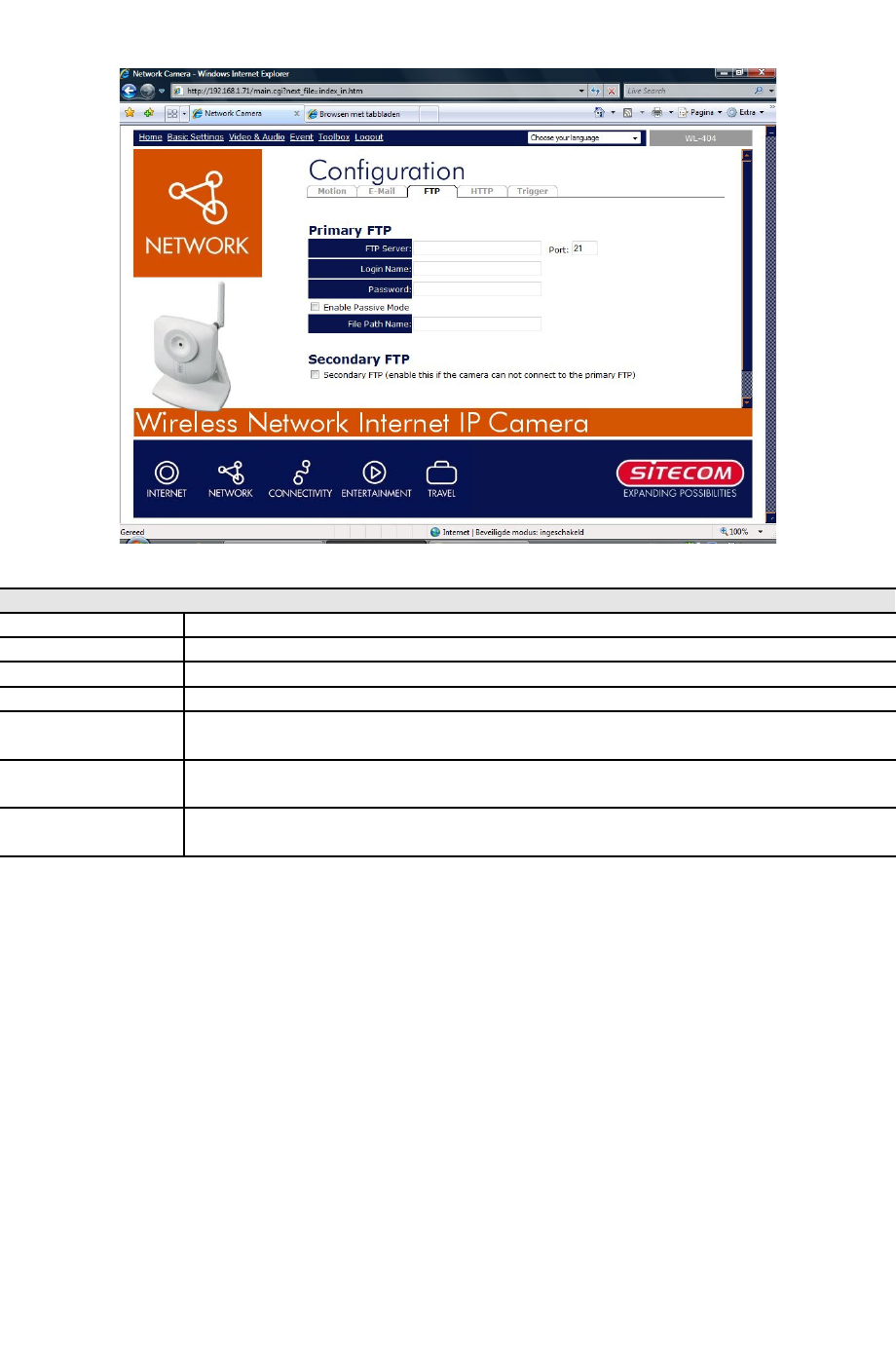
Event - FTP.....................................................................................................34
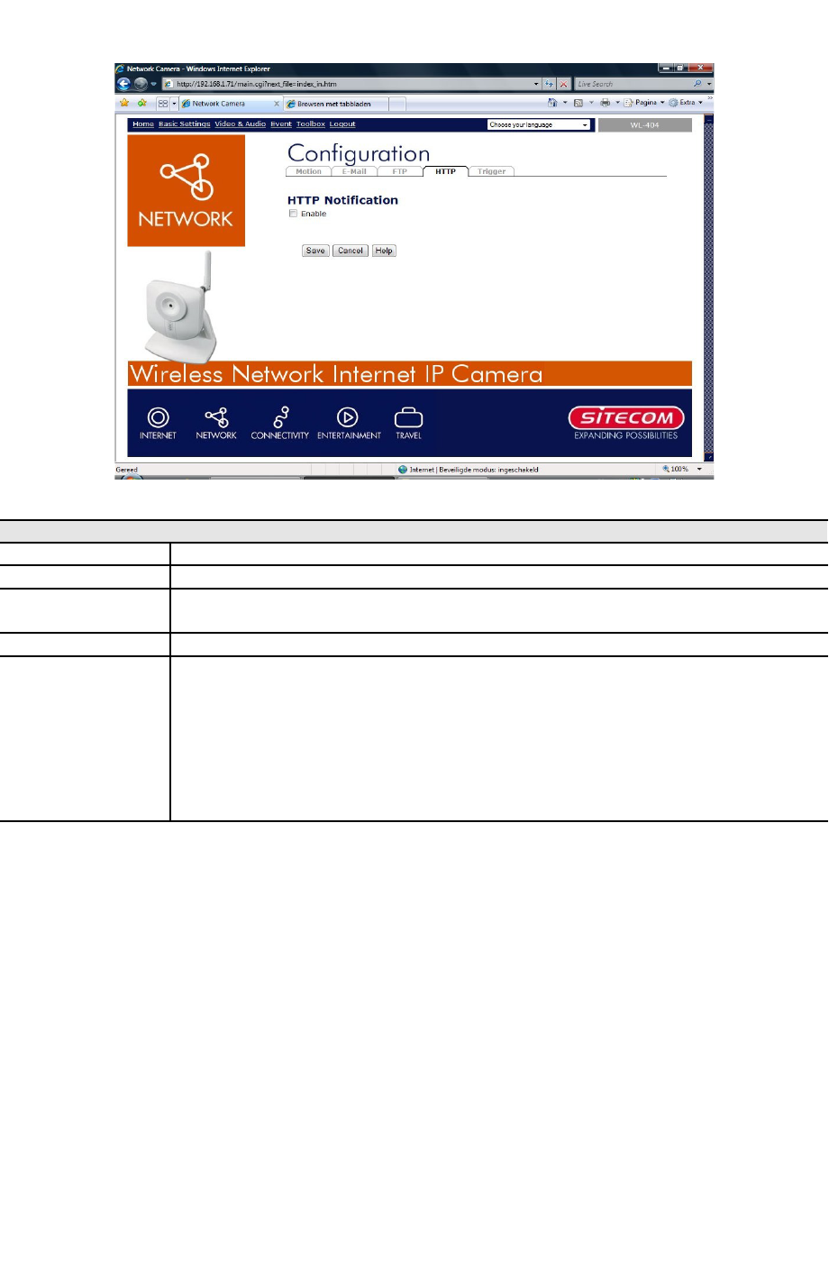
Event - HTTP...................................................................................................35
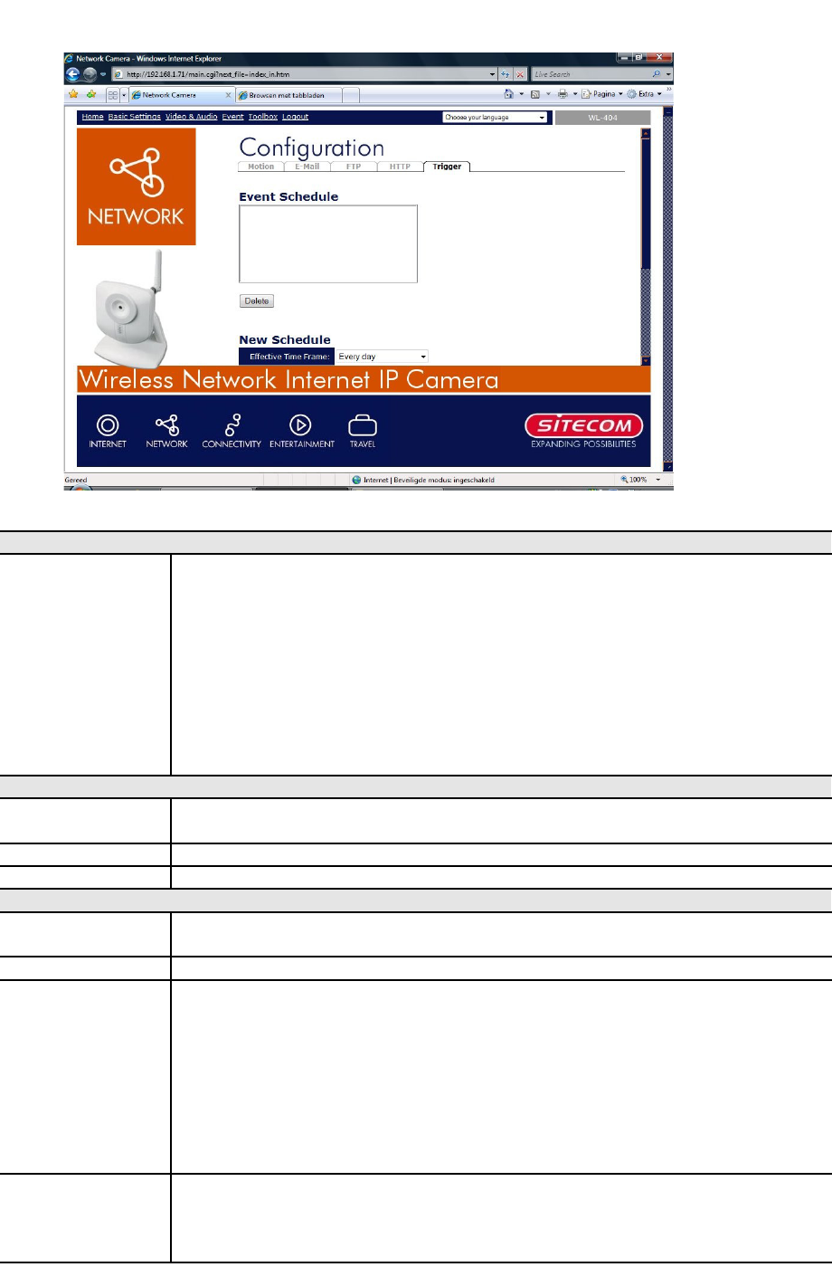
Event - Trigger................................................................................................36
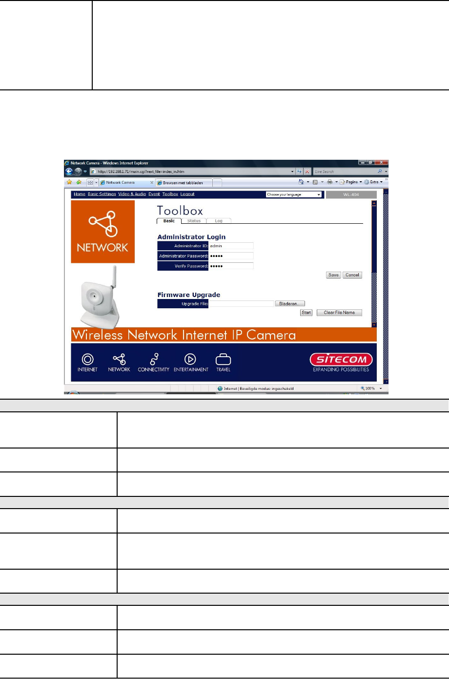
Toolbox - Basic................................................................................................37