70
16:9·············································································31, 32
3D MODE button
Accessories ······································································11
AC socket
Adjustment buttons
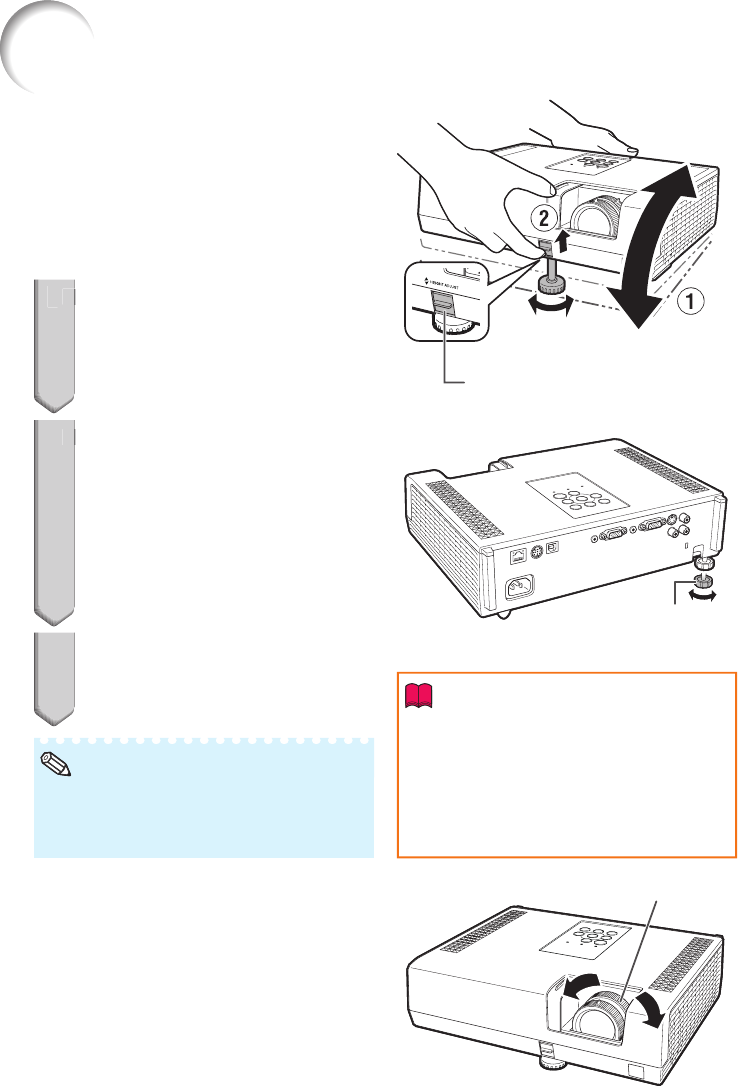
Adjustment foot
All Reset
AREA ZOOM ····································································32
Aspect ratio
Audio input
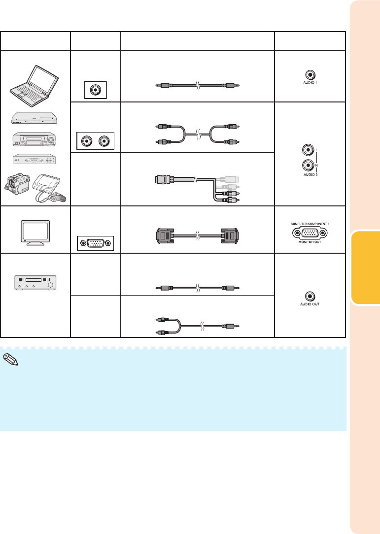
AUDIO 1, 2 terminals
Audio Mute
AUDIO OUT terminal
Auto Power Off
Auto Restart ·····································································50
Auto Sync (Auto Sync adjustment)
AUTO SYNC button··························································34
A
Background ······································································49
Batteries ···········································································15
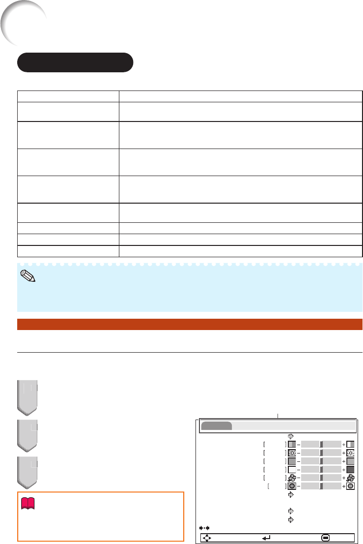
Blue ··················································································49
BORDER ·····································································31, 32
BREAK TIMER button ······················································33
Bright ················································································43
BrilliantColor
TM
Clock ················································································45
Closed Caption
CLR T
C.M.S. ··············································································43
Color ·················································································43
Complete Menu
COMPUTER2 Select
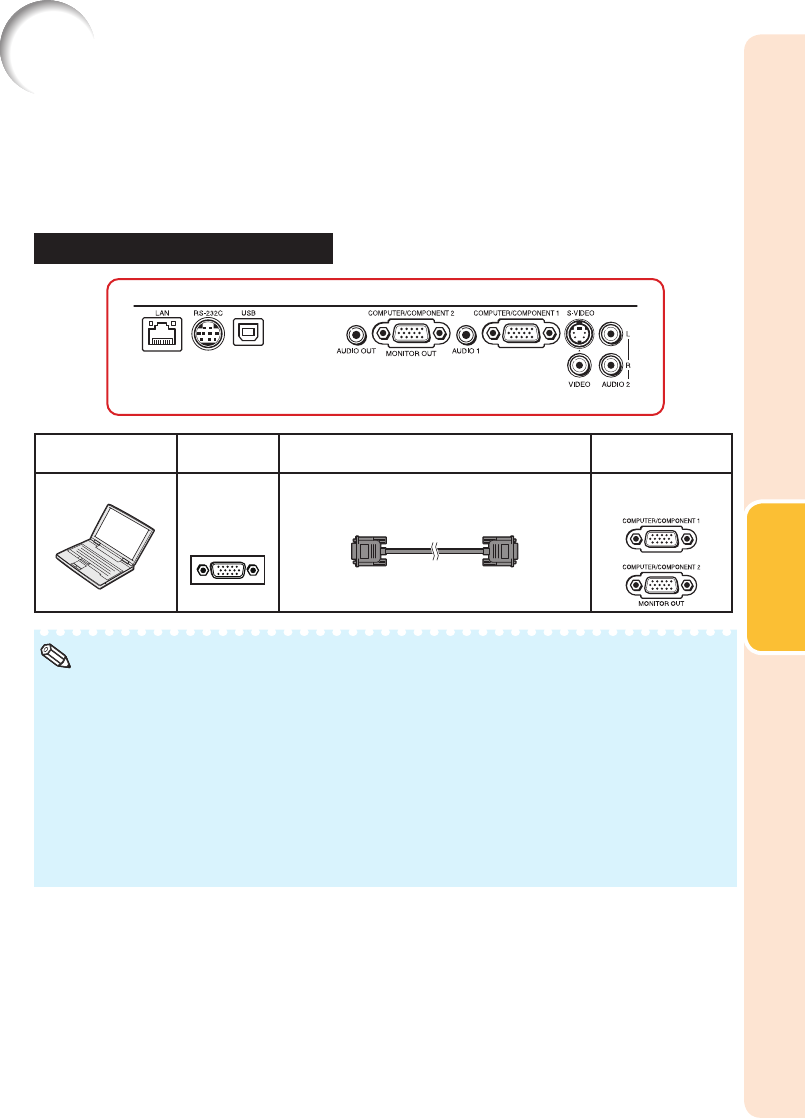
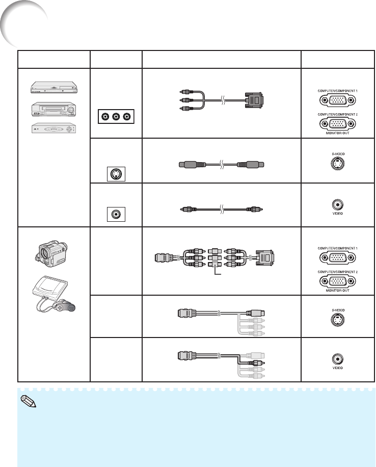
COMPUTER/
COMPONENT1, 2 input terminals
Contrast ············································································43
DHCP Client
DIN-D-sub RS-232C adaptor
DLP
®
Link
TM
······································································53
DLP
®
Link
TM
Invert
DNR ··················································································44
Eco+Quiet
ECO+QUIET button
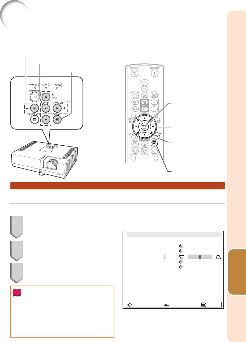
ENTER button
Exhaust vent
Fan Mode
Film Mode
Focus ring
FREEZE button
FULL ·················································································31
FUNCTION button
FUNCTION Button setting
HEIGHT ADJUST lever
H-Pos ···············································································45
Image shift
Information ·······································································40
INPUT modes
Input Search Start
Intake vent
IP Address
Kensington Security Standard connector
Keycode
Keylock
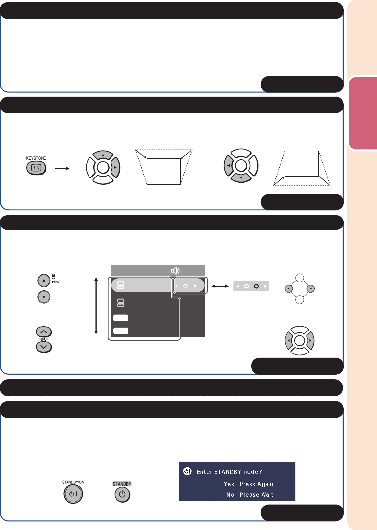
KEYSTONE button
Keystone Correction
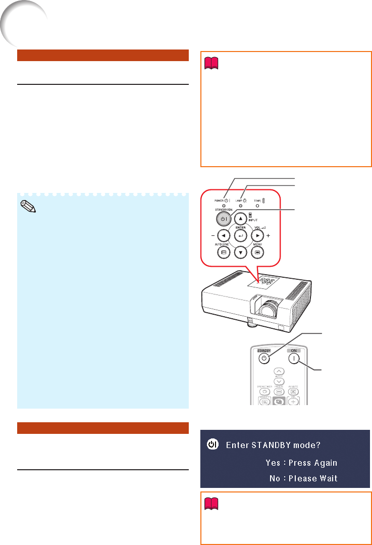
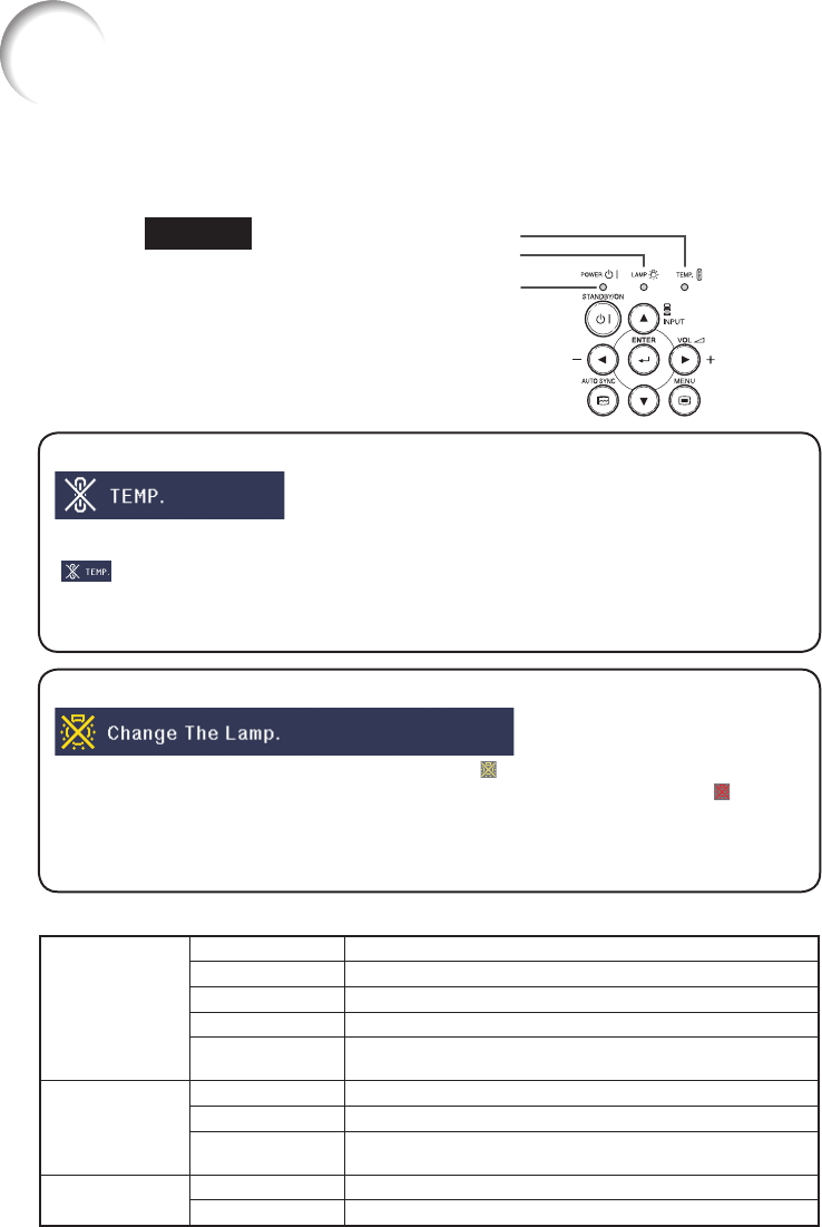
Lamp ················································································60
Lamp indicator ·································································58
Lamp Timer (Life)
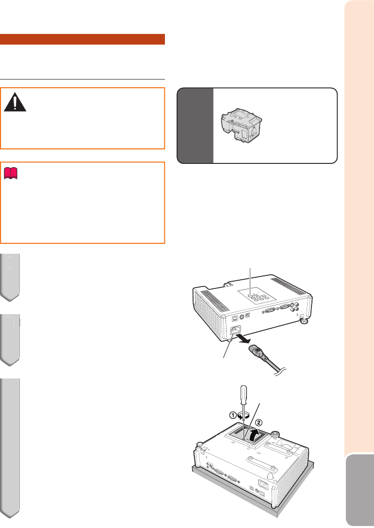
Lamp unit ·········································································61
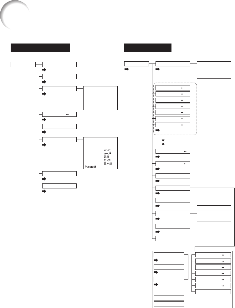
Language (on-screen display language)
LAN terminal
L-CLICK/EFFECT button
Lens shutter
Link ···················································································56
MAC Address
MAGNIFY buttons
MENU button
MONITOR OUT terminal
MOUSE/Adjustment buttons
NA
Network ············································································54
NORMAL ····································································31,
ON button
Optional accessories
OSD Display
Overscan ··········································································48
P
P
Password
PDF
Phase
Picture Adjustment
Picture Mode
PICTURE MODE button
POINTER button
Power cord
Power indicator
PRJ-ADJ1/2
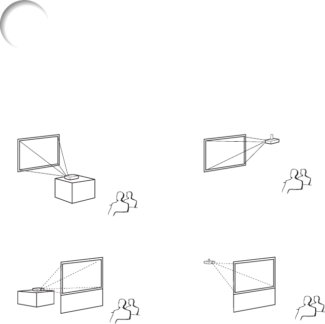
PRJ Mode
Quick Start Menu ·····························································40
R-CLICK/RETURN button
Red ···················································································43
Remote control
Remote control sensor
Replacing the lamp·····················································60, 61
Reset Network Setting
Resize ·········································································31, 47
RESIZE button
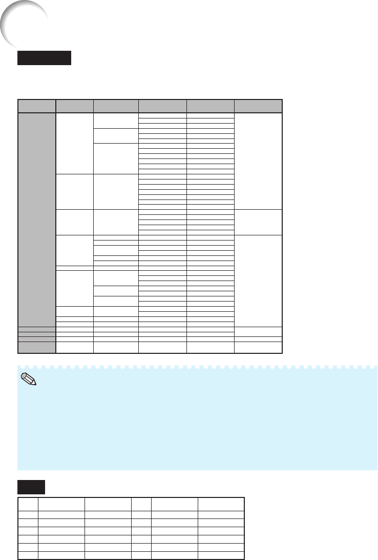
Resolution·········································································45
Restart Network ·······························································55
RGB cable
RS-232C terminal
SCR-ADJ ··········································································47
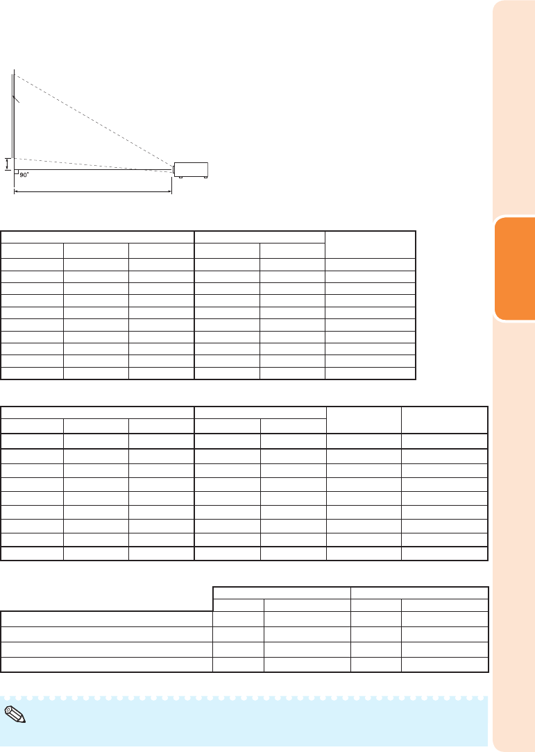
Screen Size and Projection Distance
Security bar
Setup Guide ·······························································27, 49
Sharp ················································································43
SIG-ADJ ···········································································45
Signal Info
Signal T
Speaker ············································································50
SPOT button
ST
ST
ST
Storage case
Supplied accessories
S-VIDEO terminal
System Lock
TCP/IP ··············································································55
T
Tint
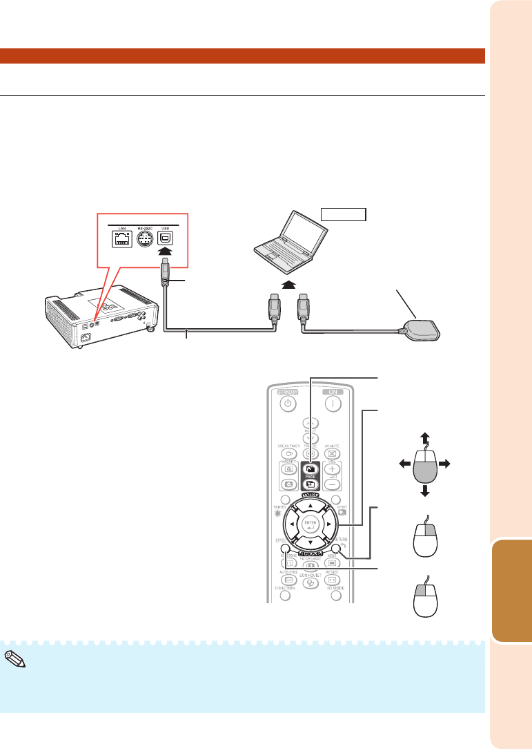
USB terminal
Video Setup
Video System
VIDEO terminal
VOL (V
V
V
Wall Color
Zoom ring
Inde