817397
61
Verklein
Vergroot
Pagina terug
1/387
Pagina verder
7N5012003BA
Inglés 7N5012003BA (07.12)
ALHAMBRA
Owners manual
ALHAMBRA Inglés (07.12)
SEAT S.A. se preocupa constantemente por mantener todos sus tipos y modelos en un desarrollo continuo. Por ello le rogamos que com-
prenda que, en cualquier momento, puedan producirse modificaciones del vehículo entregado en cuanto a la forma, el equipamiento y
la técnica. Por esta razón, no se puede derivar derecho alguno basándose en los datos, las ilustraciones y descripciones del presente
Manual.
Los textos, las ilustraciones y las normas de este manual se basan en el estado de la información en el momento de la realización de la
impresión. Salvo error u omisión, la información recogida en el presente manual es válida en la fecha de cierre de su edición.
No está permitida la reimpresión, la reproducción o la traducción, total o parcial, sin la autorización escrita de SEAT.
SEAT se reserva expresamente todos los derechos según la ley sobre el “Copyright”. Reservados todos los derechos sobre modificación.
Este papel está fabricado con celulosa blanqueada sin cloro.
© SEAT S.A. - Reimpresión: 15.07.12
Foreword
This Instruction Manual and its corresponding supplements should be read carefully to familiarise yourself
with your vehicle.
Besides the regular care and maintenance of the vehicle, its correct handling will help preserve its value.
For safety reasons, always note the information concerning accessories, modifications and part replace-
ments.
If selling the vehicle, give all of the on-board documentation to the new owner, as it should be kept with the
vehicle.
Table of Contents
Manual structure . . . . . . . . . . . . . . . . . . . . 5
Content . . . . . . . . . . . . . . . . . . . . . . . . . . . . . . . . 6
Safety First . . . . . . . . . . . . . . . . . . . . . . . . . . . . 7
Safe driving . . . . . . . . . . . . . . . . . . . . . . . . . . . . . . . 7
Dear SEAT Driver . . . . . . . . . . . . . . . . . . . . . . . . . . 7
Tips for driving . . . . . . . . . . . . . . . . . . . . . . . . . . . 7
Adjusting the seat position . . . . . . . . . . . . . . . . . 10
Transporting objects . . . . . . . . . . . . . . . . . . . . . . . 13
Seat belts . . . . . . . . . . . . . . . . . . . . . . . . . . . . . . . . . 16
Brief introduction . . . . . . . . . . . . . . . . . . . . . . . . . 16
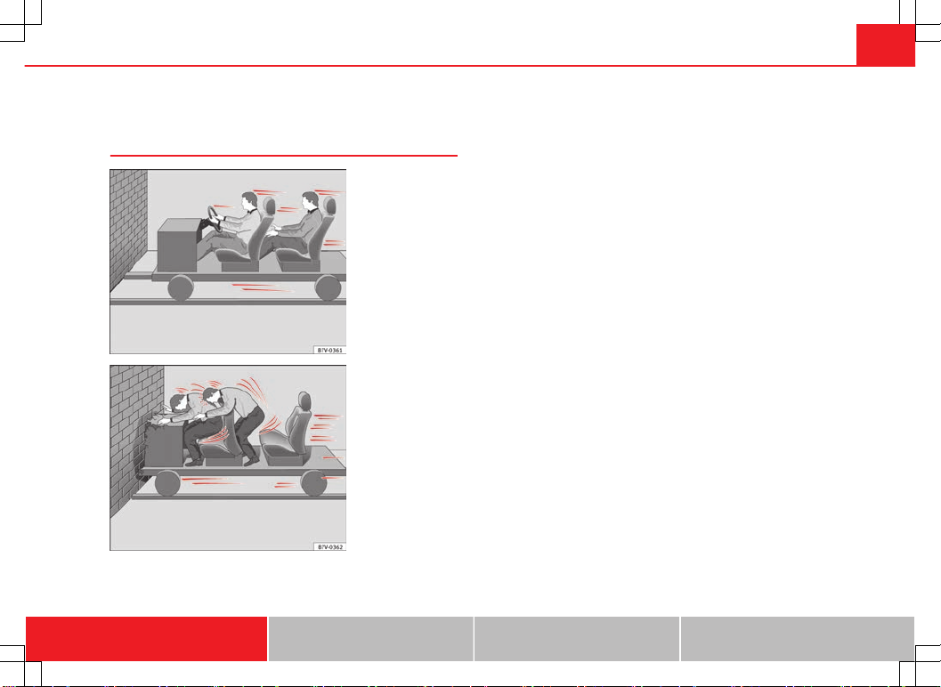
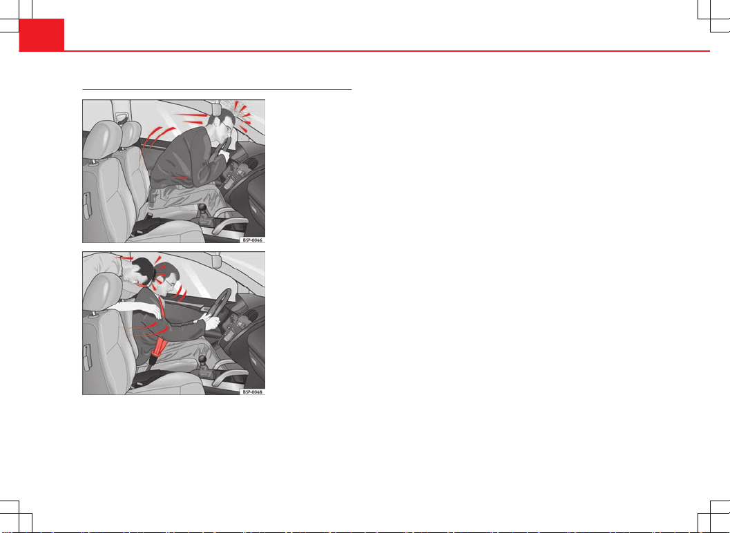
Why wear seat belts? . . . . . . . . . . . . . . . . . . . . . . 19
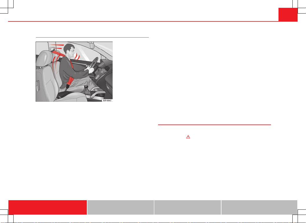
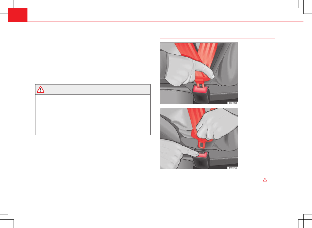
Seat belts . . . . . . . . . . . . . . . . . . . . . . . . . . . . . . . 21
Seat belt tensioners . . . . . . . . . . . . . . . . . . . . . . . 27
Airbag system . . . . . . . . . . . . . . . . . . . . . . . . . . . . . 29
Brief introduction . . . . . . . . . . . . . . . . . . . . . . . . . 29
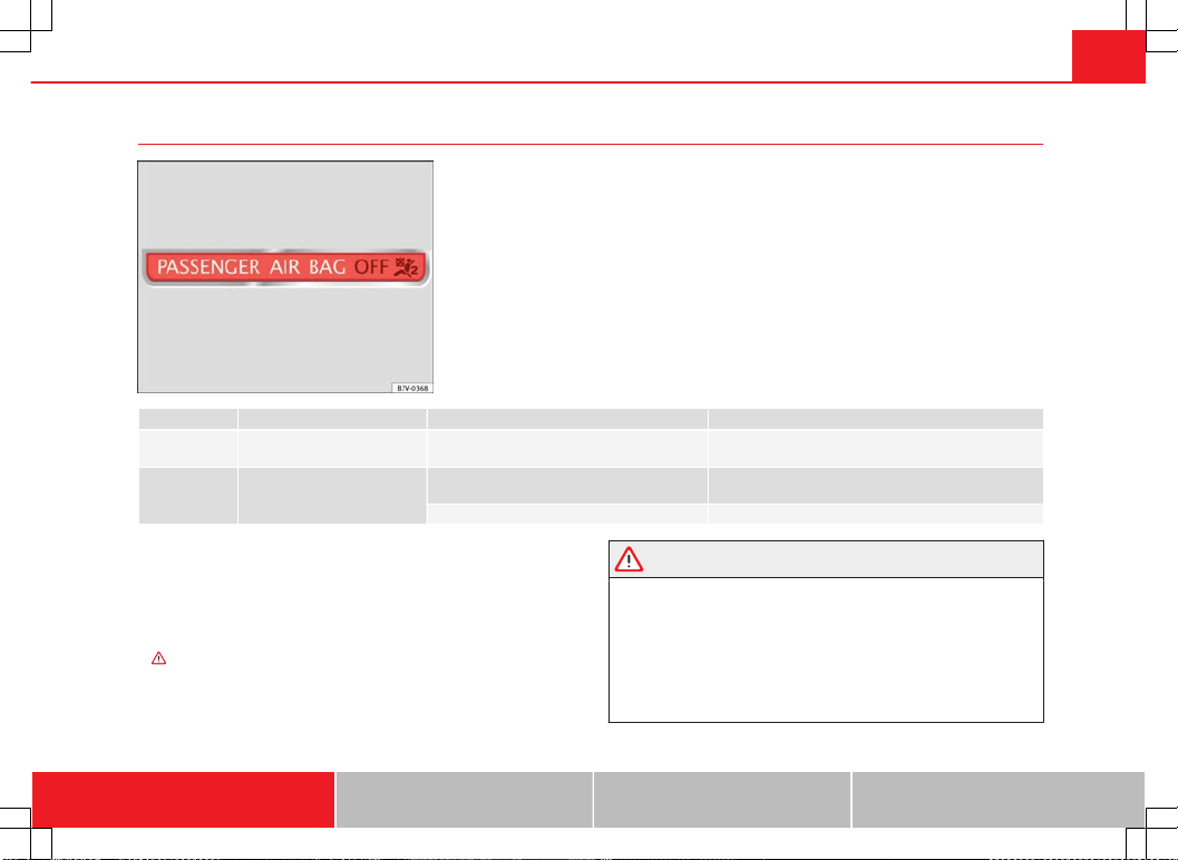
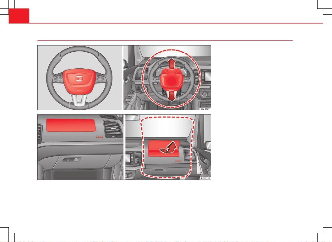
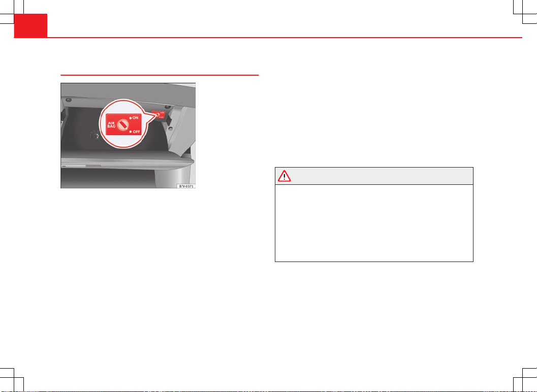
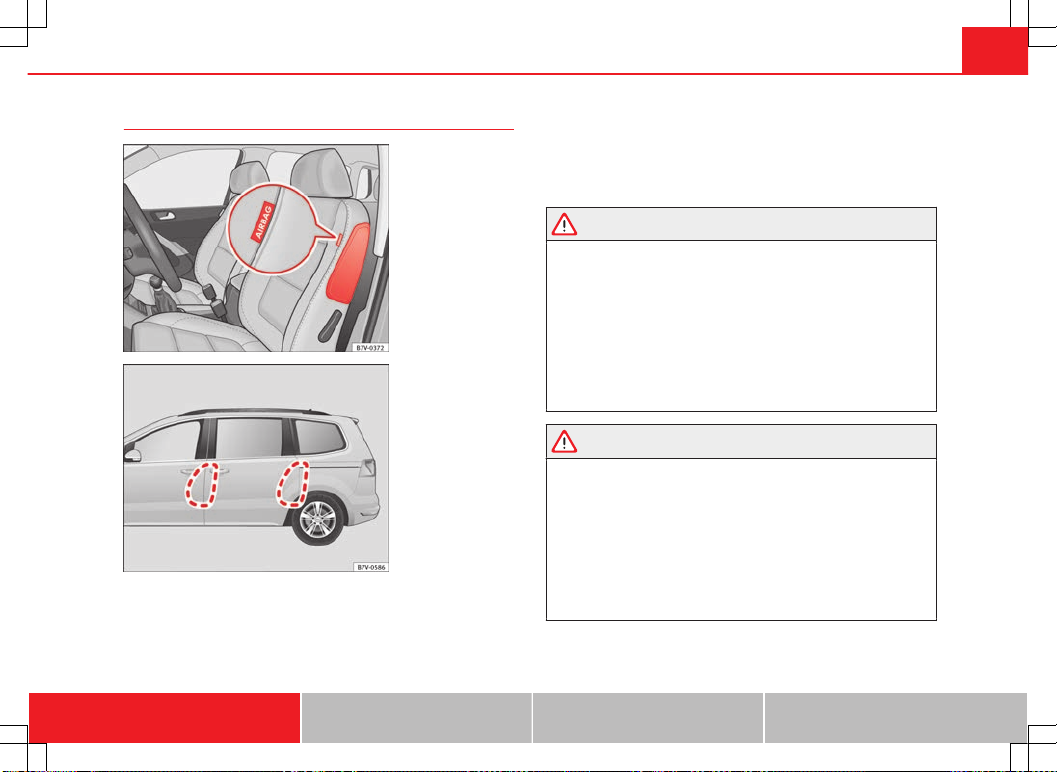
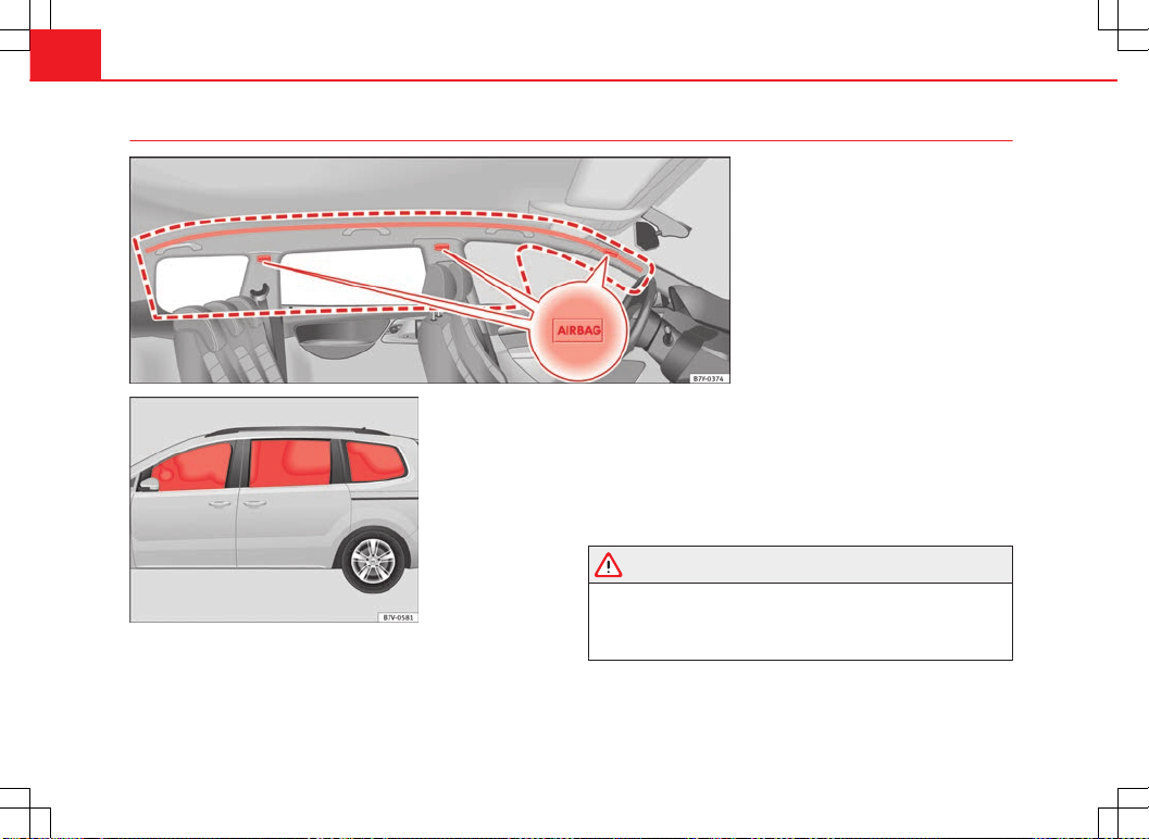
Airbag system . . . . . . . . . . . . . . . . . . . . . . . . . . . . 32
Child safety . . . . . . . . . . . . . . . . . . . . . . . . . . . . . . . 40
Child seats (accessories) . . . . . . . . . . . . . . . . . . . 40
Integrated child seat . . . . . . . . . . . . . . . . . . . . . . . 46
Operating instructions . . . . . . . . . . . . . 53
Cockpit . . . . . . . . . . . . . . . . . . . . . . . . . . . . . . . . . . . 53
Overview . . . . . . . . . . . . . . . . . . . . . . . . . . . . . . . . 53
Instrument panel . . . . . . . . . . . . . . . . . . . . . . . . . . 54
Instruments . . . . . . . . . . . . . . . . . . . . . . . . . . . . . . 57
SEAT information system . . . . . . . . . . . . . . . . . . . 62
Opening and closing . . . . . . . . . . . . . . . . . . . . . . 71
Vehicle key set . . . . . . . . . . . . . . . . . . . . . . . . . . . 71
Central locking and locking system . . . . . . . . . . . 74
Doors . . . . . . . . . . . . . . . . . . . . . . . . . . . . . . . . . . . 80
Sliding doors . . . . . . . . . . . . . . . . . . . . . . . . . . . . . 80
Rear lid . . . . . . . . . . . . . . . . . . . . . . . . . . . . . . . . . . 83
Electric windows . . . . . . . . . . . . . . . . . . . . . . . . . . 88
Panoramic sliding sunroof* . . . . . . . . . . . . . . . . . 92
Lights and visibility . . . . . . . . . . . . . . . . . . . . . . . . 95
Lights . . . . . . . . . . . . . . . . . . . . . . . . . . . . . . . . . . . 95
Sun blind . . . . . . . . . . . . . . . . . . . . . . . . . . . . . . . . 103
Windscreen wiper and washer . . . . . . . . . . . . . . . 105
Rear vision mirror . . . . . . . . . . . . . . . . . . . . . . . . . 110
Seats and storage . . . . . . . . . . . . . . . . . . . . . . . . . 114
Seat adjustment . . . . . . . . . . . . . . . . . . . . . . . . . . 114
Seat functions . . . . . . . . . . . . . . . . . . . . . . . . . . . . 117
Head restraints . . . . . . . . . . . . . . . . . . . . . . . . . . . 123
Centre armrest . . . . . . . . . . . . . . . . . . . . . . . . . . . . 126
Loading luggage compartment . . . . . . . . . . . . . . 126
Roof carrier system* . . . . . . . . . . . . . . . . . . . . . . . 139
Storage compartments . . . . . . . . . . . . . . . . . . . . . 141
Drink holders . . . . . . . . . . . . . . . . . . . . . . . . . . . . . 149
Ashtray and cigarette lighter* . . . . . . . . . . . . . . . 151
Power sockets . . . . . . . . . . . . . . . . . . . . . . . . . . . . 152
Air conditioning . . . . . . . . . . . . . . . . . . . . . . . . . . . 156
Air conditioner . . . . . . . . . . . . . . . . . . . . . . . . . . . . 156
Auxiliary heater* (additional heater) . . . . . . . . . . 164
Driving . . . . . . . . . . . . . . . . . . . . . . . . . . . . . . . . . . . . 168
Steering . . . . . . . . . . . . . . . . . . . . . . . . . . . . . . . . . 168
Stopping and starting the engine . . . . . . . . . . . . 171
Changing gear . . . . . . . . . . . . . . . . . . . . . . . . . . . . 175
Braking, stopping and parking . . . . . . . . . . . . . . 184
Start assist systems . . . . . . . . . . . . . . . . . . . . . . . 195
Parking sensor system* . . . . . . . . . . . . . . . . . . . . 199
Park Assist system* . . . . . . . . . . . . . . . . . . . . . . . 203
Rear Assist system* . . . . . . . . . . . . . . . . . . . . . . . 208
Cruise control system* . . . . . . . . . . . . . . . . . . . . . 213
Lane Assist system* . . . . . . . . . . . . . . . . . . . . . . . 216
Sign Assist* . . . . . . . . . . . . . . . . . . . . . . . . . . . . . . 219
Tiredness detection (recommendation to take a
break) . . . . . . . . . . . . . . . . . . . . . . . . . . . . . . . . . . . 222
Tyre monitoring systems . . . . . . . . . . . . . . . . . . . . 224
Practical tips . . . . . . . . . . . . . . . . . . . . . . . . . . 228
Driving and the environment . . . . . . . . . . . . . . . 228
Running-in . . . . . . . . . . . . . . . . . . . . . . . . . . . . . . . 228
Ecological driving . . . . . . . . . . . . . . . . . . . . . . . . . 228
Engine management and exhaust gas
purification system . . . . . . . . . . . . . . . . . . . . . . . . 231
Trailer towing . . . . . . . . . . . . . . . . . . . . . . . . . . . . . . 234
Introduction . . . . . . . . . . . . . . . . . . . . . . . . . . . . . . 234
Driving with a trailer . . . . . . . . . . . . . . . . . . . . . . . 236
Vehicle maintenance and cleaning . . . . . . . . . 245
Care and cleaning the vehicle exterior . . . . . . . . 245
Caring for and cleaning the vehicle interior . . . . 252
Notes for the user . . . . . . . . . . . . . . . . . . . . . . . . . 258
Accessories, replacement of parts and
modifications . . . . . . . . . . . . . . . . . . . . . . . . . . . . . 260
Accessories, replacement of parts and
modifications . . . . . . . . . . . . . . . . . . . . . . . . . . . . 260
Checking and refilling levels . . . . . . . . . . . . . . . 267
Filling the tank . . . . . . . . . . . . . . . . . . . . . . . . . . . . 267
Fuel . . . . . . . . . . . . . . . . . . . . . . . . . . . . . . . . . . . . 270
Selective Catalytic Reduction* (AdBlue) . . . . . . . 274
Working in the engine compartment . . . . . . . . . . 278
Engine oil . . . . . . . . . . . . . . . . . . . . . . . . . . . . . . . . 282
3Table of Contents
Engine coolant . . . . . . . . . . . . . . . . . . . . . . . . . . . 286
Vehicle battery . . . . . . . . . . . . . . . . . . . . . . . . . . . 291
Wheels and tyres . . . . . . . . . . . . . . . . . . . . . . . . . . 296
Wheels . . . . . . . . . . . . . . . . . . . . . . . . . . . . . . . . . . 296
Wheel trims* . . . . . . . . . . . . . . . . . . . . . . . . . . . . . 307
Changing a wheel* . . . . . . . . . . . . . . . . . . . . . . . . 309
If and when . . . . . . . . . . . . . . . . . . . . . . . . . . . . . . . 315
In case of emergency . . . . . . . . . . . . . . . . . . . . . . 315
Emergency locking and unlocking . . . . . . . . . . . . 317
Vehicle tool kit* . . . . . . . . . . . . . . . . . . . . . . . . . . . 323
Fuses . . . . . . . . . . . . . . . . . . . . . . . . . . . . . . . . . . . 325
Changing bulbs . . . . . . . . . . . . . . . . . . . . . . . . . . . 329
Starting assistance . . . . . . . . . . . . . . . . . . . . . . . . 340
Towing and tow starting . . . . . . . . . . . . . . . . . . . . 343
Technical Specifications . . . . . . . . . . . 347
Description of specifications . . . . . . . . . . . . . . . 347
Important information . . . . . . . . . . . . . . . . . . . . . 347
Information on fuel consumption . . . . . . . . . . . . 349
Towing a trailer . . . . . . . . . . . . . . . . . . . . . . . . . . . 350
Wheels . . . . . . . . . . . . . . . . . . . . . . . . . . . . . . . . . . 350
Technical specifications . . . . . . . . . . . . . . . . . . . . 351
Checking fluid levels . . . . . . . . . . . . . . . . . . . . . . . 351
Petrol engine 1.4 110 kW (150 PS) . . . . . . . . . . . 352
Petrol engine 1.4 110 kW (150 PS) Automatic . . 353
Petrol engine 2.0 147 kW (200 PS) Automatic . . 354
Diesel engine 2.0 TDI CR 85 kW (115 PS) . . . . . . 355
Diesel engine 2.0 TDI CR 100 kW (136 PS) . . . . . 357
Diesel engine 2.0 TDI CR 100 kW (136 PS)
Automatic . . . . . . . . . . . . . . . . . . . . . . . . . . . . . . . 358
Diesel engine 2.0 TDI CR 103 kW (140 PS) . . . . . 359
Diesel engine 2.0 TDI CR 103 kW (140 PS)
Automatic . . . . . . . . . . . . . . . . . . . . . . . . . . . . . . . 360
Diesel engine 2.0 TDI CR 103 kW (140 PS) All-
wheel drive . . . . . . . . . . . . . . . . . . . . . . . . . . . . . . 362
Diesel engine 2.0 TDI CR 125 kW (170 PS) . . . . . 363
Diesel engine 2.0 TDI CR 125 kW (170 PS)
Automatic . . . . . . . . . . . . . . . . . . . . . . . . . . . . . . . 364
Dimensions and capacities . . . . . . . . . . . . . . . . . 366
Index . . . . . . . . . . . . . . . . . . . . . . . . . . . . . . . . . . . 367
4Table of Contents
5Manual structure
Manual structure
What you should know before reading this manual
This manual contains a description of the equipment supplied with the ve-
hicle at the time of press. Some of the equipment hereunder described will
not be available until a later date, or is only available in certain markets.
Because this is a general manual for the ALHAMBRA, some of the equip-
ment and functions that are described in this manual are not included in all
types or variants of the model; they may vary or be modified depending on
the technical requirements and on the market; this is in no way deceptive
advertising.
The illustrations are intended as a general guide and may vary from the
equipment fitted in your vehicle in some details.
The direction indications (left, right, front, rear) appearing in this manual re-
fer to the normal forward working direction of the vehicle except when oth-
erwise indicated.
The equipment marked with an asterisk** is fitted as standard only in cer-
tain versions, and is only supplied as optional extras for some versions, or
are only offered in certain countries.
All registered marks are indicated with ®. Although the copyright sym-
bol does not appear, it is a copyrighted mark.
The section is continued on the following page.
Marks the end of a section.
WARNING
Texts preceded by this symbol contain information on safety. They warn
you about possible dangers of accident or injury.
®
CAUTION
Texts with this symbol draw your attention to potential sources of damage
to your vehicle.
For the sake of the environment
Texts preceded by this symbol contain relevant information concerning envi-
ronmental protection.
Note
Texts preceded by this symbol contain additional information.
6Content
Content
This manual is structured to provide the information you need in an organ-
ised way. The content of this Manual is divided into sections which belong
to chapters (e.g. “Air conditioning”). The entire manual is divided into five
large parts which are:
1. Safety First
Information about the vehicle equipment relating to passive safety such as
seat belts, airbags, seats, etc.
2. Operating instructions
Information about the distribution of controls in the driver position of your
vehicle, about the seat adjustment possibilities, about how to create a suit-
able climate in the vehicle interior, etc.
3. Practical tips
Tips relating to the driving, caring and maintenance of your vehicle and cer-
tain problems you can solve yourself.
4. Technical specifications
Figures, data, dimensions and measurements (for example fuel consump-
tion) of your vehicle.
5. Alphabetic index
At the end of this manual there is a detailed alphabetical index, this will
help you to quickly find the information you require.
7Safe driving
Safety First
Safe driving
Dear SEAT Driver
Safety first!
This chapter contains important information, tips, suggestions and
warnings that you should read and consider for both your own
safety and for your passengers' safety.
WARNING
This manual contains important information about the operation of
the vehicle, both for the driver and the passengers. The other sections of
the on-board documentation also contain further information that you
should be aware of for your own safety and for the safety of your passen-
gers.
Ensure that the on-board documentation is kept in the vehicle at all
times. This is especially important when lending or selling the vehicle to
another person.
Tips for driving
Introduction
Depending upon how you expect to use your vehicle, it may a good idea to
protect the engine from below. A guard underneath the engine may help to
reduce the risk of damage to the lower part of the vehicle and the oil sump
when driving over kerbs, or along dirt tracks or rough roads... SEAT recom-
mends you have the guard fitted by a Technical Service.
Additional information and warnings:
Ensure you are correctly seated ⇒ page 10
Transporting ⇒ page 13
Starting, changing gears, parking ⇒ page 171
Ecological driving ⇒ page 228
Notes for the user ⇒ page 258
WARNING
Driving under the influence of alcohol, drugs, medication or narcotics
may result in severe accidents and even loss of life.
Alcohol, drugs, medication and narcotics may significantly alter per-
ception, affect reaction times and safety while driving, which could result
in the loss of control of the vehicle.
Preparing for the journey and safe driving
Check list
For your own safety, for the safety of passengers in the car, and for that of
other road users, the following should be checked before and during each
journey ⇒  :
Safety First Operating instructions Practical tips Technical Specifications
8Safe driving
Check that the lights and turn signals operate correctly.
Check the tyre pressures (⇒ page 296) and level of fuel (⇒ page 267).
Ensure there is good visibility through all the windows.
Make sure that all objects and bags in the storage compartments, in the
luggage compartment and, where applicable, on the roof, are securely fas-
tened ⇒ page 13.
Ensure there is nothing obstructing the free passage of the foot pedals.
Use child retention systems appropriate for the child's body weight and
height ⇒ page 40.
Correctly adjust front seat, head rests and rear vision mirrors to suit your
height ⇒ page 10.
Wear close-fitting shoes which do not prevent you from using the pedals
correctly.
The driver's floor mat should be fixed to the floor, leaving the pedal area
unobstructed.
Before starting out, ensure you are correctly seated and remain in this
position throughout the journey. This applies to all passengers in the vehi-
cle ⇒ page 10.
Correctly fasten your seat belt before starting to drive and keep it se-
curely fastened throughout the journey. This applies to all passengers in the
vehicle ⇒ page 21.
Never carry more passengers than the number of available seats and
seat belts in your vehicle.
Never drive with impaired faculties (for example, due to medication, al-
cohol or drugs).
Do not allow yourself to be distracted from the traffic, for example, to re-
set or switch on a menu, by other passengers or to answer a phone call.
Always try to adapt the speed of the vehicle and your style of driving to
the condition of the ground or the road and to weather and traffic condi-
tions.
Observe the highway code and speed limits.
On long journeys, rest at regular intervals (at least every two hours).
If carrying animals, make sure they are correctly restrained in accord-
ance with their weight and size.
WARNING
Always observe traffic regulations and speed limits and try to anticipate
traffic movements. Correctly anticipating traffic situations may mean the
difference between arriving safe and sound at your destination or having
a serious accident.
Note
Regular servicing of your vehicle not only helps to keep it in good working
order but also helps to ensure road safety. Therefore, please ensure the ve-
hicle is taken for service as indicated in the Maintenance Programme. If the
vehicle is subjected to hard use, it may require certain maintenance work
before the next service date. Hard use may involve frequent driving in traffic
jams, driving in dusty areas or frequent use of the tow bar. For further infor-
mation, please refer to a Technical Service or specialised workshop.
Driving abroad
Check list
In some countries, certain safety regulations and requirements are in force
relating to exhaust gas emissions, which differ from the technical character-
istics of the vehicle. Before travelling abroad, SEAT recommends you con-
sult a Technical Service about the legal requirements and the following
points:
Does the vehicle need technical modifications for driving abroad, for ex-
ample, adjustment of the headlamps?
Does the vehicle have all the tools, diagnostics equipment and spare
parts required for inspections and repairs?
9Safe driving
Are there any SEAT dealers in the destination country?
For petrol vehicles: Is unleaded petrol available at the right octane rat-
ing?
For diesel engines: Is diesel fuel available with a low sulphur content?
Are a suitable engine oil (⇒ page 282) and other engine fluids comply-
ing with SEAT specifications available in the destination country?
Will the navigation system fitted at the factory operate correctly in the
destination country with the available navigation data?
Are special tyres required in the destination country?
CAUTION
SEAT does not accept liability for any damage to the vehicle due to the use
of a lower quality fuel, an inadequate service or the non-availability of genu-
ine spare parts.
Driving along flooded roadways
To prevent damage to the vehicle when driving through water, for example,
along a flooded road, please observe the following:
Check the depth of the water before entering the flooded zone. The wa-
ter should never come above the lower edge of the bodywork ⇒  .
Do not drive faster than a pedestrian.
Do not stop in the water, use reverse gear or switch off the engine.
Oncoming traffic will cause waves which raise the level of the water,
making it difficult to cross the water.
WARNING
When driving through water, mud, melted snow, etc., please remember
that due to damp or frozen brake discs and shoes in winter, the braking
effect may be delayed, therefore the required braking distance is greater.
Dry the brakes and remove ice by braking carefully. Ensure that you
are not endangering other road-users or breaking traffic regulations in
the process.
After driving through water, avoid sudden sharp manoeuvres.
CAUTION
Driving through flooded areas may severely damage vehicle compo-
nents such as the engine, transmission, running gear or electrical system.
Never drive through salt water as salt causes corrosion. Always rinse any
parts of the vehicle which have been in contact with salt water.
Safety First Operating instructions Practical tips Technical Specifications
10 Safe driving
Adjusting the seat position
Introduction
Number of seats
Depending on the equipment, your vehicle has a total of five or seven seats.
Each seat is equipped with a seat belt.
Equipment Seats in the
front
Seats in the sec-
ond row
Seats in the
third row
5 seats 2 3
7 seats 2 3 2
Additional information and warnings:
Seat functions ⇒ page 117
Seat belts ⇒ page 21
Airbag system ⇒ page 32
Child seats (accessories) ⇒ page 40
WARNING
An incorrect sitting position in the vehicle can lead to severe injuries or
death in the event of sudden braking or manoeuvres, collision or acci-
dents or if the airbag deploys.
Before the vehicle moves, assume the proper sitting position and
maintain it throughout the trip. This also includes fastening the seat
belt.
Never transport more people than there are seats with a seat belt
available in the vehicle.
WARNING (Continued)
Children must always be protected with an approved child restraint
system suited to their height and weight ⇒ page 40, ⇒ page 32.
Always keep your feet in the footwell while the vehicle is in motion.
Never, for example, put your feet on the surface of a seat or on the dash
panel and never put them out of a window. Otherwise the airbag and seat
belt offer insufficient protection and the risk of injury in the event of an
accident is increased.
WARNING
Before every trip, adjust the seat, the seat belt and the head restraints
and instruct your passengers to fasten their seat belts properly.
Move the front passenger seat back as far as possible.
Adjust the driver seat so that there is a distance of at least 25 cm
(10 inches) between the centre of your chest and the hub of the steering
wheel. Adjust the driver seat so that you are able to press the accelera-
tor, brake and clutch pedals to the floor with your knees slightly angled
and that the distance between your knees and the dash panel is at least
10 cm (4 inches). If your physical constitution prevents you from meeting
these requirements, contact a specialised workshop to make any modifi-
cations required.
Never drive with the seat backrest tilted far back. The further the seat
backrests are tilted to the rear, the greater the risk of injury due to incor-
rect positioning of the belt web or to the incorrect sitting position!
Never drive with the seat backrest tilted forwards. Should a front air-
bag deploy, it could throw the seat backrest backwards and injure the
passengers of the rear seats.
Sit as far away as possible from the steering wheel and the dash pan-
el.
11Safe driving
WARNING (Continued)
Keep your back straight and resting completely against the seat back-
rest and the front seats correctly adjusted. Never place any part of your
body in the area of the airbag or very close to it.
If passengers on the rear seats are not sitting in an upright position,
the risk of severe injury due to incorrect positioning of the belt web in-
creases.
WARNING
Incorrect seat adjustment may lead to accidents and severe injuries.
Only adjust the seats when the vehicle is stationary, as the seats
could move unexpectedly while the vehicle is in motion and you could
lose control of the vehicle. Furthermore, an incorrect position is adopted
when adjusting the seat.
Only adjust the height, seat backrest and forwards or backwards po-
sition of the seat when there is nobody in the seat adjustment area.
There must be no objects blocking the seat adjustment area.
Only adjust the height, angle and longitudinal position of the rear
seats when nobody is in the way.
The seat adjustment and lock areas must be kept clean.
Danger of injuries due to an incorrect sitting position
If the seat belts are worn incorrectly or not at all, the risk of severe injuries
increases. Seat belts can provide optimal protection only if the belt web is
properly worn. The seat belt cannot offer its full protection if the belt web is
not positioned correctly. This could result in severe and even fatal injuries.
The risk of severe or fatal injuries is especially increased when a deploying
airbag strikes a vehicle occupant who has assumed an incorrect sitting po-
sition. The driver is responsible for all passengers in the vehicle, particularly
children.
The following list shows just some examples of incorrect sitting positions
which can be dangerous to all vehicle occupants.
Whenever the vehicle is in motion:
Never stand in the vehicle.
Never stand on the seats.
Never kneel on the seats.
Never tilt your seat backrest too far to the rear.
Never lean against the dash panel.
Never lie on the rear bench.
Never sit on the front edge of a seat.
Never sit sideways.
Never lean out of a window.
Never put your feet out of a window.
Never put your feet on the dash panel.
Never put your feet on the surface of a seat or seat backrest.
Never travel in a footwell.
Never sit on the armrests.
Never travel on a seat without wearing the seat belt.
Never carry any person in the luggage compartment.
WARNING
Every incorrect sitting position increases the risk of severe or fatal inju-
ries in the event of accidents or sudden braking or manoeuvres.
All passengers must assume the proper sitting position and be prop-
erly belted in while travelling.
Vehicle occupants in incorrect sitting positions, not wearing their
seat belt or too close to the airbag run the risk of suffering severe or fatal
injuries, particularly if the airbag deploys and hits an occupant sitting in
an incorrect position.
Safety First Operating instructions Practical tips Technical Specifications
12 Safe driving
Correct sitting position
Fig. 1 The correct dis-
tance between the driver
and the steering wheel
must be at least 25 cm
(10 inches)
Fig. 2 Correct belt web
and head restraint posi-
tions
The correct sitting positions for the driver and passengers are shown below.
If your physical constitution prevents you from maintaining the correct sit-
ting position, contact a specialised workshop for help with any special devi-
ces. The seat belt and airbag can only provide optimum protection if a cor-
rect sitting position is adopted. SEAT recommends visiting a Technical Serv-
ice.
For your own safety and to reduce the risk of injury in the event of an acci-
dent or sudden braking or manoeuvre, SEAT recommend the following posi-
tions:
Valid for all vehicle occupants:
Adjust the head restraint so that its upper edge is at the same level as
the top of your head, or as close as possible to the same level as the top of
your head and under no circumstances below eye level. Keep the back of
your neck as close as possible to the head restraint ⇒ Fig. 1 and ⇒ Fig. 2.
Short people must lower the head restraint completely, even if your
head is below its upper edge.
Tall people must raise the head restraint completely.
Adjust the seat backrest to an upright position so that your back rests
completely against it.
Always keep your feet in the footwell while the vehicle is in motion.
Adjust and fasten your seat belt correctly ⇒ page 21.
Also valid for the driver:
Adjust the steering wheel so that there is a distance of at least 25 cm
(10 inches) between it and your chest ⇒ Fig. 1 and so that you can hold the
steering wheel with both hands on the outside of the ring at the 9 o'clock
and 3 o'clock positions with your arms slightly bent.
The adjusted steering wheel must face your chest and not your face.
Adjust the driver seat forwards or backwards so that you are able to
press the accelerator, brake and clutch pedals to the floor with your knees
slightly angled and the distance between your knees and the dash panel is
at least 10 cm (4 inches) ⇒ Fig. 1.
Adjust the height of the driver seat so that you can easily reach the top
of the steering wheel.
Keep both feet in the footwell so that you have the vehicle under control
at all times.
13Safe driving
Also valid for the front passenger:
Move the front passenger seat back as far as possible for optimum pro-
tection should the airbag deploy.
Transporting objects
Introduction
Always transport heavy loads in the luggage compartment and place the
seat backs in a vertical position. Always use the anchors provided with suit-
able rope to secure heavy objects. Never overload the vehicle. Both the car-
rying capacity as well as the distribution of the load in the vehicle have ef-
fects on the driving behaviour and braking ability ⇒  .
Additional information and warnings:
Rear lid ⇒ page 83
To lower the front passenger seat back ⇒ page 117
Light ⇒ page 95
Luggage compartment ⇒ page 126
Roof carrier ⇒ page 139
Towing mode ⇒ page 236
Wheels and tyres ⇒ page 296
WARNING
Unsecured or incorrectly secured objects can cause serious injury in case
of a sudden manoeuvring or breaking or in case of an accident. This is es-
pecially true when objects are struck by a detonating airbag and fired
through the vehicle interior. To reduce the risks, please note the follow-
ing:
Secure all objects in the vehicle. Always keep equipment and heavy
objects in the luggage compartment.
Always secure objects with suitable rope or slings so that they cannot
enter the areas around the front or side airbags in case of sudden braking
or an accident.
Always ensure that objects inside the vehicle cannot move into the
area of the airbags while driving.
While driving, always keep object compartments closed.
Remove all objects from the front passenger seat when this is fol-
lowed down. When the seat backrest is folded down, it presses on small
and light objects and these are detected by the weight sensor on the
seat; this sends false information to the airbag control unit.
While the seat backrest of the front passenger seat is folded, the
front airbag must remain disabled and the PASSENGER AIRBAG OFF
light on.
Objects secured in the vehicle should never be placed in such a way
as to make passengers sit in an incorrect position.
If secured objects occupy a seat then this should not be occupied or
used by anybody.
Safety First Operating instructions Practical tips Technical Specifications
14 Safe driving
WARNING
The driving behaviour and braking ability change when transporting
heavy and large objects.
Adjust your speed and driving style to visibility, road, traffic and
weather conditions.
Accelerate gently and carefully.
Avoid sudden braking and manoeuvres.
Brake early.
Transporting a load
Secure all objects in the vehicle
Distribute the load throughout the vehicle, on the roof and in a trailer as
uniformly as possible.
Transport heavy objects as far forward as possible in the luggage com-
partment and lock the seat backs in the vertical position.
Secure luggage in the luggage compartment with suitable straps on the
fastening rings ⇒ page 126.
Check the headlight adjustment ⇒ page 95.
Use the suitable tyre pressure according to the load being transported.
Read the tire inflation information label ⇒ page 296.
For vehicles with a tire pressure indicator, change the vehicle load status
⇒ page 224.
CAUTION
Objects on the shelf could chafe against the wires of the heating element in
the heated rear window and cause damage.
Note
Please note the information about loading a trailer ⇒ page 236 and the
roof carrier system ⇒ page 139.
Driving with the rear lid open
Driving with the rear lid open creates an additional risk. Secure all objects
and secure the rear lid correctly and take all measures possible to reduce
toxic gases from entering the vehicle.
WARNING
Driving with the rear lid unlocked or open could cause serious injuries.
Always drive with the rear lid closed.
Secure all objects in the vehicle. Loose items could fall out of the ve-
hicle and injure other road users or damage other vehicles.
Drive particularly carefully and think ahead.
Avoid sudden manoeuvres and braking given that this could cause an
uncontrolled movement of the open rear lid.
When transporting objects that protrude out of the luggage compart-
ment, indicate them suitably. Observe legal requirements.
If objects must project out of the luggage compartment, the rear lid
must never be used to “secure” or “attach” objects.
If a baggage rack is fitted on the rear lid, it should be removed before
travelling with the rear lid open.
15Safe driving
WARNING
Toxic gases may enter the vehicle interior when the rear lid is open. This
could cause loss of consciousness, carbon monoxide poisoning, serious
injury and accidents.
To avoid toxic gases entering the vehicle always drive with the rear lid
closed.
In exceptional circumstances, if you must drive with the rear lid open,
observe the following to reduce the entry of toxic gases inside the vehi-
cle:
Close all windows and the sliding sunroof.
Turn off the air recirculation for the heating and air conditioner.
Open all of the air outlets in the dash panel.
Turn the heating fan and heater to the highest level.
CAUTION
An open rear lid changes the length and height of the vehicle.
Driving a loaded vehicle
For the best handling when driving a loaded vehicle, note the following:
Secure all objects ⇒ page 14.
Accelerate gently and carefully.
Avoid sudden braking and manoeuvres.
Brake early.
If necessary, read the instructions for driving with a trailer ⇒ page 236.
If necessary, read the instructions for driving with a roof carrier system
⇒ page 139.
WARNING
A sliding load could considerably affect the stability and safety of the ve-
hicle resulting in an accident with serious consequences.
Secure loads correctly so they do not move.
When transporting heavy objects, use suitable ropes or straps.
Lock the seat backs in vertical position.
Specific vehicle weight information
The instructions in the official vehicle documents take precedence. All the
technical data provided in this documentation is applicable to the basic
model. The vehicle data label in the Maintenance Programme or the vehicle
documentation shows which engine is installed in your vehicle.
The figures may be different depending whether additional equipment is fit-
ted, for different models and for special vehicles.
WARNING
Exceeding the maximum authorised weight and the load on the axles
could cause damage to the vehicle, accidents and serious injuries.
The real load on the axles should never exceed the maximum permit-
ted.
The load and its distribution in the vehicle have effects on the vehicle
handling and the braking ability. Always drive at a suitable speed.
CAUTION
Distribute the load as uniformly and as low down on the vehicle as possible.
When transporting heavy objects in the luggage compartment, these
should be placed as far forward as possible or over the rear axle to have as
little influence on handling as possible.
Safety First Operating instructions Practical tips Technical Specifications
16 Seat belts
Seat belts
Brief introduction
Introduction
Check the condition of all the seat belts at regular intervals. If you notice
that the belt webbing, fittings, retractor mechanism or buckle of any of the
belts is damaged, the belt must be replaced immediately by a specialised
workshop ⇒  . The specialised workshop must use the appropriate spare
parts corresponding to the vehicle, the equipment and the model year. SEAT
recommends visiting a Technical Service.
Additional information and warnings:
Adjust the seat position ⇒ page 10
Airbag system ⇒ page 32
Child seats (accessories) ⇒ page 40
Integrated child seats ⇒ page 46
Accessories, parts replacement, repairs and modifications ⇒ page 260
WARNING
Unbuckled or badly buckled seat belts increase the risk of severe or even
fatal injuries. The seat belt cannot offer its full protection if it is not fas-
tened and used correctly.
Seats belts are the most effective ways of reducing the risk of sus-
taining severe or fatal injuries In the event of an accident. Seat belts
must be correctly fastened when the vehicle is in motion to protect the
driver and all vehicle occupants.
WARNING (Continued)
Before each trip, every occupant in the vehicle occupants must sit
properly, correctly fasten the seat belt belonging to his or her seat and
keep it fastened throughout the trip. This also applies to other vehicle
occupants when driving in town.
When travelling, children must be secured in the vehicle with a child
restraint system suitable for their weight and height and with the seat
belts correctly fastened ⇒ page 40.
Instruct your passengers to fasten their seat belts properly before
driving off.
Insert the latch plate into the buckle for the appropriate seat and en-
sure it is engaged. Using the latch plate in the buckle of another seat will
not protect you properly and may cause severe injuries.
Do not allow liquids or foreign bodies to enter the buckle fastenings.
This could damage the buckles and seat belts.
Never unbuckle your seat belt when the vehicle is moving.
Never allow more than one passenger to share the same seat belt.
Never hold children or babies on your lap sharing the same seat belt.
Loose, bulky clothing (such as a jacket) impairs the proper fit and
function of the seat belt.
WARNING
It is extremely dangerous to drive using damaged seat belts and could re-
sult in serious injury or loss of life.
Avoid damaging the seat belt by jamming it in the door or the seat
mechanism.
17Seat belts
WARNING (Continued)
If the fabric or other parts of the seat belt are damaged, the seat belts
could break in the event of an accident or sudden braking.
Always have damaged seatbelts replaced immediately by seat belts
approved for the vehicle in question by SEAT. Seat belts which have been
worn in an accident and stretched must be replaced by a specialised
workshop. Renewal may be necessary even if there is no apparent dam-
age. The belt anchorage should also be checked.
Never attempt to repair, modify or remove a seat belt yourself. All re-
pairs to seat belts, retractors and buckles must be carried out by a speci-
alised workshop.
Warning lamp
Fig. 3 Warning lamp on
the instrument panel
Fig. 4 Example of seat
belt status display for the
rear seats (here, a 7-seat
vehicle) on the instru-
ment panel above the
second row and below
the third row of seats
Lights up
or flash-
es
Possible cause Solution
Driver's seat belt not fas-
tened or front passenger seat
belt not fastened if the front
passenger seat is occupied.
Fasten seat belts!
Objects on the front passen-
ger seat.
Remove any objects from the
front passenger seat and store
them safely.
Some control and warning lamps on the instrument panel will come on to
check certain functions when the ignition is switched on. They will switch off
after a few seconds.
An audible warning will be heard for a maximum of 90 seconds if the seat
belts are not fastened as the car drives off and reaches a speed of more
then 25 km/h (15 mph) or if the seat belts are unfastened while the vehicle
is in motion. The seat belt warning lamp will also flash.
The warning lamp does not switch off until the driver and front passenger
fasten their seat belts while the ignition is switched on.
Safety First Operating instructions Practical tips Technical Specifications
18 Seat belts
Seat belt status display for rear seats
The seat belt status display on the instrument panel informs the driver,
when the ignition is switched on, whether any passengers in the rear seats
have fastened their seat belts. The symbol indicates that the passenger
in this seat has fastened “his or her” seat belt ⇒ Fig. 4.
The seat belt status is displayed for around 30 seconds when a seat belt in
the rear seats is fastened or unfastened. You can switch off this display by
pressing the 0.0 / SET button.
The seat belt status flashes for a maximum of 30 seconds when a seat belt
in the rear seats is unfastened while the vehicle is in motion. An audible
warning will also be heard if the vehicle is travelling at over 25 km/h
(15 mph).
The rear seat display can be enabled or disabled by a Technical Service.
WARNING
Unbuckled or badly buckled seat belts increase the risk of severe or even
fatal injuries. The optimal protection from seat belts can be achieved only
if you use them properly.
19Seat belts
Why wear seat belts?
Frontal collisions and the laws of physics
Fig. 5 Vehicle about to
hit a wall: the vehicle oc-
cupants are not wearing
seat belts
Fig. 6 The vehicle hits
the wall: the vehicle oc-
cupants are not wearing
seat belts
It is easy to explain how the laws of physics work in the case of a head-on
collision: when a vehicle starts moving ⇒ Fig. 5, this is a certain amount of
energy known as kinetic energy both in the vehicle and in the vehicle occu-
pants.
The higher the speed and the greater the weight of the vehicle, the more
energy there is to be absorbed in an accident.
The most significant factor, however, is the speed of the vehicle. If the
speed doubles from 25 km/h to 50 km/h (15 to 30 mph), for example, the
kinetic energy is multiplied by four.
The amount of kinetic energy depends on the speed of the vehicle and the
weight of the vehicle and its passengers. The higher the speed and the
greater the weight of the vehicle and the vehicle occupants, the more ener-
gy there is to be absorbed in an accident.
Vehicle occupants not wearing seat belts are not “attached” to the vehicle.
As a result, in a frontal collision they will continue to move forward at the
speed their vehicle was travelling just before the impact until something
stops them! Because the vehicle occupants in our example are not restrain-
ed by seat belts, all of the vehicle occupants' kinetic energy has to be ab-
sorbed at the point of impact ⇒ Fig. 6.
At speeds of 30 km/h to 50 km/h (20 to 30 mph), the forces acting on bod-
ies in a collision can easily exceed one tonne (1000 kg). At greater speed
these forces are even higher.
This example applies not only to head-on collisions, but to all accidents and
collisions.
Safety First Operating instructions Practical tips Technical Specifications
20 Seat belts
Dangers of not using the seat belt
Fig. 7 A driver not wear-
ing a seat belt is thrown
forward violently
Fig. 8 The unbelted rear
passenger is thrown for-
ward violently, hitting the
driver wearing a seat belt
Many people believe that the vehicle occupants can protect themselves
with their hands in a minor collision. This is false!
Even at low speeds, the forces acting on the body in a collision are so great
that it is not possible to brace oneself with just one's arms and hands. In a
frontal collision, unbelted passengers are thrown forward and will make vio-
lent contact with the steering wheel, dash panel, windscreen or whatever
else is in the way ⇒ Fig. 7.
The airbag system is not a substitute for seat belts. When triggered, airbags
provide only additional protection. Airbags do not deploy in all types of ac-
cident. All vehicle occupants (including the driver) must be wearing seat
belts properly during the trip, even if the vehicle is equipped with airbag
systems. This will reduce the risk of critical or fatal injuries in the event of an
accident – regardless of whether an airbag is fitted for the seat.
The airbag is only deployed once. To achieve the best possible protection,
the seat belt must always be worn properly so that you will be protected in
accidents in which no airbag is deployed. Vehicle occupants not wearing
belts could be thrown from the vehicle and sustain even more severe or fa-
tal injuries.
It is also important for the rear passengers to wear seat belts properly, as
they could otherwise be thrown forward violently in an accident. Rear pas-
sengers who do not use seat belts endanger not only themselves but also
the driver and other vehicle occupants ⇒ Fig. 8.
21Seat belts
Seat belt protection
Fig. 9 Drivers with prop-
erly worn seat belts will
not be thrown forward in
the event of sudden brak-
ing
Wearing a correctly fastened seat belt can significantly change the situa-
tion. Properly worn seat belts hold the vehicle occupants in the correct sit-
ting positions and substantially reduce the kinetic energy in the event of an
accident. Seat belts also help to prevent uncontrolled movements that
could lead to severe injuries. In addition, properly worn seat belts reduce
the danger of being thrown from the car ⇒ Fig. 9.
Passengers wearing their seat belts correctly benefit greatly from the ability
of the belts to absorb kinetic energy. The front crumple zones and other
passive safety features (such as the airbag system) are also designed to ab-
sorb the kinetic energy generated in a collision. Taken together, all these
features reduce the energy released and decrease the risk of injury.
Our examples describe frontal collisions. Of course, properly worn seat belts
substantially reduce the risk of injury in all other types of accidents. This is
why it is so important to fasten seat belts before every trip, even when just
driving “around the corner”. Ensure that your passengers wear their seat
belts as well.
Accident statistics have shown properly worn seat belts to be an effective
means of considerably reducing the risk of severe injury and improving the
chances of survival in a serious accident. Furthermore, properly worn seat
belts improve the protection provided by deployed airbags in the event of
an accident. For this reason, wearing a seat belt is required by law in most
countries.
Although your vehicle is equipped with airbags, the seat belts must be fas-
tened and worn. The front airbags, for example, are only triggered in some
frontal accidents. The front airbags will not be triggered during minor frontal
collisions, minor side collisions, rear collisions, rolls or accidents in which
the airbag trigger threshold value in the control unit is not exceeded.
Therefore, you should always wear your seat belt and ensure that your pas-
sengers have fastened their seat belts properly before you drive off!
Seat belts
Using seat belts
Checklist
Using seat belts ⇒  :
Check the condition of all the seat belts at regular intervals.
Keep the seat belts clean.
Keep the belt web, the latch plate and the buckle free of foreign bodies
and liquids.
Do not jam or damage the seat belt or the latch plate when closing the
door, for example.
Never remove, modify or repair the seat belt or belt fastening mecha-
nisms.
Fasten your seat belt properly before each trip and keep it fastened.
Safety First Operating instructions Practical tips Technical Specifications
22 Seat belts
Twisted seat belt
If it is difficult to remove the seat belt from the guide, the seat belt may
have become twisted inside the side trim after being wound too quickly on
unfastening:
Pull out the seat belt completely, carefully pulling on the latch plate.
Untwist the belt and guide it back, assisting it by hand.
The seat belt must be fastened even if it is impossible to untwist it. In this
case, the twisted area must not be in an area in direct contact with your
body. Have the seat belt untwisted urgently by a specialised workshop.
WARNING
An improperly handled seat belt increases the risk of sustaining severe
or fatal injuries.
Regularly check that the seat belts and their components are in per-
fect condition.
Always keep your seat belt clean.
Do not jam or damage the seat belt or rub it with sharp edges.
Make sure there are no liquids or foreign bodies on the latch plate
and in the buckle.
Fastening or unfastening a seat belt with one buckle
Fig. 10 Insert the latch
plate into the buckle
Fig. 11 Release the latch
plate from the buckle
Properly worn seat belts hold the vehicle occupants in the position that
most protects them in the event of an accident or sudden braking ⇒  .
23Seat belts
Fastening the seat belt
Fasten your seat belt before each trip.
Adjust the front seat and head restraint correctly ⇒ page 10.
Engage the seat backrest of the rear seat in an upright position ⇒  .
Pull the latch plate and place the belt webbing evenly across your chest
and lap. Do not twist the seat belt when doing so ⇒  .
Engage the latch plate in the buckle of the corresponding seat ⇒ Fig. 10.
Pull the belt to ensure that the latch plate is securely engaged in the
buckle.
Unfastening the seat belt
The seat belt must not be unfastened until the vehicle has come to a stand-
still ⇒  .
Press the red button on the buckle ⇒ Fig. 11. The latch plate is released
from the buckle.
Guide the belt back by hand so that it rolls up easily and the trim will not
be damaged.
WARNING
An incorrectly worn seat belt web can cause severe or fatal injuries in the
event of an accident.
The seat belt cannot offer its full protection unless the seat backrests
are in an upright position and the seat belt is worn correctly, according to
your size.
Unbuckling your seat belt while the vehicle is in motion can cause se-
vere or fatal injuries in the event of an accident or sudden braking.
Fastening or unfastening the seat belt with two buckles
Fig. 12 Fasten the seat
belt on the centre seat in
the second row of seats
Properly worn seat belts hold the vehicle occupants in the position that
most protects them in the event of an accident or sudden braking ⇒  .
The seat belts for the centre seat in the second row of seats and for the
seats in the third row of seats are fastened using two buckles.
Fastening the seat belt
Fasten your seat belt before each trip.
Adjust the rear seat and head restraint correctly ⇒ page 10.
Engage the seat backrest of the rear seat in an upright position ⇒  .
Use latch plate of the belt ⇒ Fig. 12 1 to pull the seat belt down. Do not
twist the seat belt when doing so ⇒  .
Engage the latch plate 1 in the buckle of the corresponding seat A.
Use the latch plate 2 to pull the seat belt across your lap.
Engage the latch plate 2 in the buckle of the corresponding seat B.
Pull the belt to ensure that both latch plates are securely engaged in the
buckles.
Safety First Operating instructions Practical tips Technical Specifications
24 Seat belts
Unfastening the seat belt
The seat belt must not be unfastened until the vehicle has come to a stand-
still ⇒  .
Press the red button on the buckle A. The latch plate is released from
the buckle.
Press the red button on the buckle B. The latch plate is released from
the buckle.
Guide the belt back by hand so that it rolls up easily and the trim will not
be damaged.
WARNING
An incorrectly worn seat belt web can cause severe or fatal injuries in the
event of an accident.
The seat belt cannot offer its full protection unless the seat backrests
are in an upright position and the seat belt is worn correctly, according to
your size.
Unbuckling your seat belt while the vehicle is in motion can cause se-
vere or fatal injuries in the event of an accident or sudden braking.
Note
Seat belts with two buckles include a diagram to show how to fasten the
seat belt.
25Seat belts
Seat belt position
Fig. 13 Correct belt web and head restraint positions
Fig. 14 Correct position-
ing of seat belts during
pregnancy
Seat belts offer their maximum protection in the event of an accident and
reduce the risk of sustaining severe or fatal injuries only when they are
properly positioned. Furthermore, if the webbing is correctly positioned, the
seat belt will hold the vehicle occupants in the optimum position to ensure
the airbag provides the utmost protection. The seat belt must therefore al-
ways be worn and the webbing correctly positioned.
Incorrectly worn seat belts can cause severe or even fatal injuries
⇒ page 10, Adjusting the seat position.
Correct seat belt position
The shoulder part of the seat belt must lie on the centre of the shoulder,
never across the neck or the arm, under the arm or behind the shoulder.
The lap part of the seat belt must lie across the pelvis, never across the
stomach.
The seat belt must lie flat and fit comfortably. Pull the belt tight if neces-
sary to take up any slack.
In the case of pregnant women, the seat belt must lie evenly across the
chest and as low as possible over the pelvis, never across the stomach and
must be worn properly at all times during the pregnancy ⇒ Fig. 14.
Safety First Operating instructions Practical tips Technical Specifications
26 Seat belts
Adapting the position of the belt webbing to your size
The seat belt can be adapted using the following equipment:
Belt height adjustment for the front seats.
Seat height adjustment (front seats).
WARNING
An incorrectly worn seat belt web can cause severe injuries in the event
of an accident or sudden braking or manoeuvre.
The seat belt cannot provide optimum protection if it is not correctly
worn and the seat backrest is not tilted slightly backwards.
The seat belt itself or a loose seat belt can cause severe injuries if the
belt moves from hard areas of the body to soft areas (e.g. the stomach).
The shoulder part of the seat belt must lie on the centre of the shoul-
der, never across the neck or the arm.
The seat belt must lie flat and fit comfortably on the torso
The lap part of the seat belt must lie across the pelvis, never across
the stomach. The seat belt must lie flat and fit comfortably on the pelvis
Pull the belt tight if necessary to take up any slack.
For pregnant women, the lap part of the seat belt must lie as low as
possible over the pelvis and always lie flat, “surrounding” the stomach.
Do not twist the seat belt while it is fastened.
Never pull the seat belt away from your body using your hand.
Do not lie the seat belt across rigid or fragile objects, e.g. glasses,
pens or keys.
Never use seat belt clips, retaining rings or similar instruments to al-
ter the position of the belt webbing.
Note
If you physical constitution prevents you from maintaining the correct posi-
tion of the belt webbing, contact a specialised workshop for help with any
special devices to ensure the optimum protection of the seat belt and air-
bag. SEAT recommends visiting a Technical Service.
Belt height adjustment
Fig. 15 Next to the front
seats: belt height adjust-
er
Using the height adjusters for the front seats and the outer seats of the sec-
ond row, the position of the seat belts can be adjusted in the shoulder area
according to the height of the occupant:
Keep the guide device pressed down in the direction of the arrow
⇒ Fig. 15.
Move the guide device up or down until the seat belt lies over the centre
of your shoulder ⇒ page 25, Seat belt position.
Release the guide device.
Pull the belt sharply to check that the device is engaged securely.
27Seat belts
WARNING
Never adjust the belt height while the vehicle is in motion.
Seat belt tensioners
Automatic belt retainer, belt tensioner, belt tension limiter
Seat belts are part of the vehicle safety concept ⇒ page 32 and consist of
the following important functions:
Automatic belt retainer
Every seat belt is equipped with an automatic belt retainer on the shoulder
belt. If the belt is pulled slowly or during normal driving, the system allows
for total freedom of movement on the shoulder belt. However, during sud-
den braking, during travel in mountains or bends and during acceleration,
the automatic belt retainer on the seat belt is locked is pulled quickly.
Belt tensioners
The seat belts on the front seats and the outer seats of the second row are
equipped with belt tensioners.
Sensors will trigger the belt tensioners during severe head-on, lateral and
rear collisions and retract and tighten the seat belts. If the seat belt is
loose, it is retracted to reduce the forwards movement of vehicle occupants
or movement in the direction of the collision. The belt tensioner works in
combination with the airbag system. The belt tensioner will not be triggered
in the event of the vehicle overturning if the side airbags are not deployed.
If the belt tensioner is triggered, a fine dust is produced. This is normal and
it is not an indication of fire in the vehicle.
Belt tension limiter
The belt tension limiter reduces the force of the seat belt on the body in the
event of an accident.
Note
The relevant safety requirements must be observed when the vehicle or
components of the system are scrapped. These requirements are known to
specialised workshops ⇒ page 27.
Service and disposal of belt tensioners
If you work on the belt tensioners or remove and install other parts of the
vehicle when performing other repair work, the seat belt may be damaged.
The consequence may be that, in the event of an accident, the belt tension-
ers function incorrectly or not at all.
So that the effectiveness of the belt tensioner is not reduced and that re-
moved parts do not cause any injuries or environmental pollution, regula-
tions must be observed. These requirements are known to specialised work-
shops.
WARNING
Improper handling and homemade repairs of seat belts, automatic belt
retainers and tension devices increase the risk of sustaining severe or fa-
tal injuries. The belt tensioner may fail to trigger or may trigger in the
wrong circumstances.
Never attempt to repair, adjust or remove or install parts of the belt
tensioners or seat belts. Any work must be performed by a specialised
workshop only ⇒ page 260.
Belt tensioners and automatic belt retainers cannot be repaired and
must be replaced.
Safety First Operating instructions Practical tips Technical Specifications
28 Seat belts
For the sake of the environment
Airbag modules and belt tensioners may contain perchlorate. Observe the
legal requirements for their disposal.
29Airbag system
Airbag system
Brief introduction
Introduction
Front airbags have been installed for both driver and passenger. The front
airbags can also protect the chest and head of driver and passenger if the
seats, seat belts head restraints and, for the driver, the steering wheel are
correctly adjusted and used. Airbags are considered as additional safety
equipment. An airbag cannot replace the seat belt, which must be worn at
all times, even in front seats where front airbags have been installed.
Additional information and warnings:
Driving tips ⇒ page 7
Correct sitting positions ⇒ page 10
Seat belts ⇒ page 21
Child seats (accessories) ⇒ page 40
Care and cleaning of the vehicle interior ⇒ page 252
Accessories, parts replacement, repairs and modifications ⇒ page 260
Notes for the user ⇒ page 258
WARNING
Never exclusively trust the airbag system as a means of protection.
Even when triggered, airbag protection is only auxiliary.
WARNING (Continued)
The airbags provide the best protection when the seat belts are prop-
erly fastened, thus reducing the risk of sustaining injuries ⇒ page 21,
Seat belts.
Before each trip, every occupant must sit properly, correctly fasten
the seat belt belonging to his or her seat and keeping it fastened
throughout the trip. This rule is valid for all vehicle occupants.
WARNING
Vehicle occupants sitting in the front of the vehicle must never carry any
objects in the deployment space between them and the airbags, as this
increases the risk of sustaining injuries if the airbag is triggered. This
modifies the airbag deployment space or the objects may fly uncontrolla-
bly and hit your body.
Never carry objects in your hand or on your lap while the vehicle is in
motion.
Never transport objects on the front passenger seat. In the event of
sudden braking and manoeuvres, the objects may end up in the airbag
deployment space and fly uncontrollably around the vehicle interior if the
airbag is activated.
Vehicle occupants of the front and outer rear seats must never carry
any other people, pets or objects in the deployment space between them
and the airbags. Make sure children and other passengers also respect
this recommendation.
Safety First Operating instructions Practical tips Technical Specifications
30 Airbag system
WARNING
The airbag system provides protection for one accident only. If they have
been deployed, they must be replaced.
Ensure deployed airbags and the system components involved are im-
mediately replaced with new, SEAT-approved components for the vehicle.
Have any repairs or modifications carried out at a specialised work-
shop. Specialised workshops have the necessary tools, diagnostics
equipment, repair information and qualified personnel.
Never fit recycled or reused airbag components in your vehicle.
Never modify the airbag system components.
WARNING
If the airbags are triggered, a fine dust is produced. This is normal and it
is not an indication of fire in the vehicle.
This fine dust may irritate the skin and eyes and cause breathing dif-
ficulties, particularly in people suffering from or who have suffered from
asthma or other illnesses of the respiratory tract. To reduce breathing dif-
ficulties, get out of the vehicle and open and doors and windows to
breath in fresh air.
Should you touch the dust, wash your hands and face using a mild
soap and water before you eat.
Prevent the dust from affecting the eyes or open wounds.
Rinse your eyes with water if you have dust in them.
WARNING
Solvents cause the surfaces of the airbag modules to become porous. If
an airbag is accidentally triggered, the detachment of plastic parts could
cause serious injury.
Never clean the dash panel and the surfaces of the airbag modules
with cleaners containing solvents.
31Airbag system
Control lamp
Fig. 16 Control lamp for
disabling the front pas-
senger front airbag on
the dash panel
lights up Digit Possible cause Solution
Instrument panel Fault in airbag system and seat belt tensioners. Have the system checked immediately by a specialised
workshop.
 Dash panel Fault in the airbag system. Have the system checked immediately by a specialised
workshop.
Front passenger front airbag disabled. Check whether the airbag should remain disabled.
Several warning and control lamps should light up for a few seconds when
the ignition is switched on, signalling that the function is being verified.
They will switch off after a few seconds.
If the PASSENGER AIR BAG  control lamp does not remain lit or if it is lit
together with the control lamp on the instrument panel and the front pas-
senger front airbag is disabled, there may be a fault in the airbag system
⇒  .
WARNING
In the event of a fault in the airbag system, the airbag may not trigger
correctly, may fail to trigger or may even trigger unexpectedly, leading to
severe or fatal injuries.
Have the airbag system checked immediately by a specialised work-
shop.
Never mount a child seat in the front passenger seat or remove the
mounted child seat! The front passenger front airbag may deploy during
an accident in spite of the fault.
Safety First Operating instructions Practical tips Technical Specifications
32 Airbag system
CAUTION
Always pay attention to any lit control lamps and to the corresponding de-
scriptions and instructions to avoid damage to the vehicle.
Airbag system
Description and function of the airbag
The airbag can protect vehicle occupants in the event of an accidents, cush-
ioning the movement of the occupants in the direction of the collision in
frontal and side accidents.
Deployed airbags fill with a propellant gas. This causes the airbag covers to
break and the airbags to deploy extremely quickly in their entire deploy-
ment space within fractions of a second. When an occupant with the seat
belt properly fastened puts pressure on the inflated airbag, the propellant
gas escapes to absorb the force of the impact and slow the movement. This
reduces the risk of severe or fatal injuries. Airbag deployment does not
mean that other types of injury such as swelling, bruising, burns and skin
injuries can be ruled out.
Airbags do not protect the arms or the lower part of the body.
The most important factors for triggering the airbag are the type of accident,
the angle of impact, the vehicle speed and the characteristics of the object
the vehicle hits. Therefore, airbags are not triggered every time the vehicle
is visibly damaged.
The airbag system is designed to be triggered in collisions with a severe im-
pact. The front, curtain, side and knee airbags may be triggered under spe-
cial circumstances. The scope of any visible damage to the vehicle is not an
indication of airbag deployment.
Airbags act in conjunction with three-point seat belts in the event of certain
accidents, when the vehicle deceleration rate is severe enough to trigger
the airbags. Airbags only deploy once and only under certain circumstan-
ces. Seat belts remain present to offer protection in situations where air-
bags are not triggered or where they have already deployed. For example,
when a vehicle hits another after an initial collision or is hit by another vehi-
cle.
The airbag system is an integral part of the car's passive safety system. The
airbag system can only work effectively when the vehicle occupants are
wearing their seat belts correctly and have adjusted the head restraints
properly ⇒ page 10.
Vehicle safety components
The following safety equipment makes up the vehicle safety design to re-
duce the risk of severe and fatal injuries. Depending on the vehicle equip-
ment, some equipment may not be fitted in the vehicle or may not be avail-
able in some markets.
Optimised seat belts for all seats.
Belt tensioners for the driver and front passenger and, where applicable,
on the outer seats of the second row of seats in combination with the side
airbags.
Furthermore, belt tension limiters for the driver's and front passenger
seat belt.
Belt height adjustment for the front seats and, where applicable, the
outer seats of the second row of seats.
Seat belt warning lamp
Front airbags for driver and passenger.
Side airbags for the driver, front passenger and, where applicable, the
outer seats of the second row of seats.
Left and right curtain airbags.
One airbag for the driver's knees.
Airbag control lamp .
PASSENGER AIR BAG  control lamp.
33Airbag system
Control units and sensors.
Height-adjustable head restraint optimised for rear collisions.
Adjustable steering column.
Where applicable, mountings for child seats on the rear seats and on
the front passenger seat.
Where applicable, mountings for the child seat upper retaining strap.
Situations in which the front, knee, side and curtain airbag does not
deploy:
If the ignition is switched off during the collision.
In frontal collisions when the deceleration measured by the control unit
is too low.
In minor side collisions.
In rear collisions.
In the event of the vehicle overturning.
When the impact speed is lower than the reference value set in the con-
trol unit.
Safety First Operating instructions Practical tips Technical Specifications
34 Airbag system
Front airbags
Fig. 17 Location and deployment area of the front air-
bag for the driver
Fig. 18 Location and deployment area of the front air-
bag for the front passenger
In conjunction with the seat belts, the front airbag system gives the driver
and the front passenger additional protection for the head and chest in the
event of a severe frontal collision. Always remains as far away as possible
from the front airbag. This way, the front airbags can completely deploy
when triggered, providing their maximum protection.
The front airbag for the driver is located in the steering wheel ⇒ Fig. 17 and
the airbag for the front passenger is located in the dash panel ⇒ Fig. 18. Air-
bags are identified by the word “AIRBAG”.
35Airbag system
When the front airbags are triggered they fill the zones marked in red (de-
ployment area) ⇒ Fig. 17. Therefore, objects should never be placed or
mounted in these areas ⇒  , Factory-fitted accessories are outside the
range of the front airbag for the driver and the front passenger, e.g. the
baseplate for the mobile phone support.
The airbag covers fold out of the steering wheel or dash panel when the
driver and front passenger front airbags are triggered ⇒ Fig. 18. The airbag
covers remain connected to the steering wheel or the dash panel.
WARNING
The airbag is deployed at high speed in fractions of a second.
Always keep the deployment areas of the front airbags free.
Never secure objects to the covers or in the deployment area of the
airbag modules, e.g. drink holders or phone supports.
The deployment space between the front passengers and the airbags
must not in any case be occupied by other passenger, pets and objects.
Never fix any object to the windscreen above the front airbag on the
front passenger side.
Do not alter, cover or stick anything to the steering wheel hub or the
surface of the airbag module on the passenger side of the dash panel.
WARNING
Front airbags are deployed in front of the steering wheel ⇒ Fig. 17 and
the dash panel ⇒ Fig. 18.
When driving, always hold the steering wheel on the outer edge of
the ring with both hands: 9 o'clock and 3 o'clock position.
WARNING (Continued)
Adjust the driver seat so that there is at least 25 cm distance between
your chest and the hub of the steering wheel. If your physical constitu-
tion prevents you from meeting these requirements, make sure you con-
tact a specialised workshop.
Adjust the front passenger seat so there is as much distance as possi-
ble between the front passenger and the dash panel.
Types of front passenger front airbag systems
There are two different SEAT front passenger front airbag systems:
A B
Characteristics of the front passen-
ger front airbag that can only be dis-
abled in a specialised workshop.
Characteristics of the front passen-
ger front airbag that can be disabled
manually ⇒ page 36.
Name: airbag system Name: airbag system with front
passenger front airbag disabling.
Control lamp on the instrument
panel.
Control lamp on the instrument
panel.
Front passenger front airbag loca-
ted in the dash panel.
Front passenger front airbag loca-
ted in the dash panel.
PASSENGER AIR BAG  control
lamp on the dash panel.
Key switch in the glove compart-
ment on the front passenger side of
the dash panel.
Safety First Operating instructions Practical tips Technical Specifications
36 Airbag system
Deactivating and activating the front passenger front
airbag using the key switch
Fig. 19 In the glove com-
partment on the front
passenger side: key
switch for disabling and
enabling the front pas-
senger front airbag
The front passenger front airbag must be disabled when a rear-facing child
seat is mounted.
Disabling the front passenger front airbag
Switch the ignition off.
Open the glove compartment on the front passenger side.
Unfold the key shaft ⇒ page 71.
Using the vehicle key, turn the key switch to OFF ⇒ Fig. 19.
Close the glove compartment on the front passenger side.
The PASSENGER AIR BAG  control lamp on the dash panel will re-
main lit while the ignition is switched on ⇒ page 31.
Activating the front passenger front airbag
Switch the ignition off.
Open the glove compartment on the front passenger side.
Using the vehicle key, turn the key switch to ON ⇒ Fig. 19.
Close the glove compartment on the front passenger side.
Check that the PASSENGER AIR BAG OFF control lamp on the dash pan-
el does not light up while the ignition is switched on ⇒ page 31.
How to know whether the front passenger front airbag is disabled
Disabling of the front passenger front airbag is only indicated by the PAS-
SENGER AIR BAG  control lamp that remains lit on the dash panel (
remains yellow) ⇒ page 31, Control lamp.
If the PASSENGER AIR BAG  control lamp on the centre console does not
remain lit or is lit in combination with the control lamp on the instrument
panel, a child restraint system cannot be mounted on the front passenger
seat for safety reasons. The front passenger front airbag may deploy during
an accident.
WARNING
The front passenger front airbag must only be disabled in special cases.
Disable and activate the front passenger front airbag when the igni-
tion is switched off to avoid damage to the airbag system.
It is the driver's responsibility to ensure that the key operated switch
is set to the correct position.
Only disable the front passenger front airbag when a child seat is to
be mounted under exceptional circumstances.
As soon as the child seat is no longer needed on the front passenger
seat, reconnect the front passenger front airbag.
37Airbag system
Side airbags
Fig. 20 On the side of
the front seat: location of
the side airbag
Fig. 21 Range of action
of the front and rear side
airbags. With 5 and 7
seats.
The side airbags are located in the outer cushion of the driver and front pas-
senger seat backrests ⇒ Fig. 20. Depending on the equipment of the model,
the outer seats of the second row of seats may also be fitted with side air-
bags, located between the seat backrests and the access area. Their posi-
tion is indicated by the word “AIRBAG”. The red area (dotted line) ⇒ Fig. 21
shows the field of action of the side airbags.
In a side collision, the side airbags are triggered on the affected side of the
vehicle, thus reducing the risk of injury to passengers on that side.
WARNING
The airbag is deployed at high speed in fractions of a second.
Always keep the deployment areas of the side airbags free.
Vehicle occupants of the front and outer rear seats must never carry
any other people, pets or objects in the deployment space between them
and the airbags.
The built-in coat hooks should be used only for lightweight clothing.
Do not leave any heavy or sharp-edged objects in the pockets.
Do not mount accessories on the doors.
Only used protective covers for the seats that are approved for the ve-
hicle. Otherwise, the side airbag would be obstructed when deployed.
WARNING
Incorrect handling of the driver's and front passenger seat could prevent
the side airbag from deploying properly and cause severe injuries.
Never remove the front seats of the vehicle or modify any of their
components.
Great forces must not be exerted on the seat backrest bolsters be-
cause the side airbags might not deploy correctly, might not deploy at all
or might deploy unexpectedly.
Any damage to the original seat upholstery or around the seams of
the side airbag units must be repaired immediately by a specialised
workshop.
Safety First Operating instructions Practical tips Technical Specifications
38 Airbag system
Curtain airbags
Fig. 22 On the left side of the vehicle: location and de-
ployment area of the curtain airbag
Fig. 23 Deployed curtain
airbags
The curtain airbags are located on the driver and front passenger side
above the doors ⇒ Fig. 22. Airbags are identified by the word “AIRBAG”.
The area framed red ⇒ Fig. 22 is covered by the curtain airbag when it is de-
ployed (deployment area). Therefore, objects should never be placed or
mounted in these areas.
In a side collision, the curtain airbag on the side affected will be deployed.
The airbag covers the windows and pillars.
In a side collision, the curtain airbags for the front and outer rear seats re-
duce the risk of injury to the areas of the body facing the impact.
WARNING
The airbag is deployed at high speed in fractions of a second.
Always keep the deployment areas of the curtain airbags free.
Do not fix objects to the cover or in the deployment area of the cur-
tain airbag.
39Airbag system
WARNING (Continued)
Vehicle occupants of the front and outer rear seats must never carry
any other people, pets or objects in the deployment space between them
and the airbags.
The built-in coat hooks should be used only for lightweight clothing.
Do not leave any heavy or sharp-edged objects in the pockets.
Do not mount accessories on the doors.
Do not fit curtains to the windows other than those expressly ap-
proved for use in the vehicle.
Only turn the sun blinds towards the windows if there is no object,
e.g. pens or garage remote controls, secured to the sun blind.
Knee airbag
Fig. 24 On the driver
side: location of the knee
airbag
Fig. 25 On the driver
side: Radius of action of
the knee airbag
The knee airbag is located on the driver side below the dash panel
⇒ Fig. 24. Airbags are identified by the word “AIRBAG”.
The area framed red ⇒ Fig. 25 A is covered by the knee airbag when it is
deployed (deployment area). Therefore, objects should never be placed or
mounted in these areas.
WARNING
The airbag is deployed at high speed in fractions of a second.
The knee airbag is deployed in front of the driver's knees. Always
keep the deployment areas of the knee airbags free.
Never not fix objects to the cover or in the deployment area of the
knee airbag.
Adjust the driver seat so that there is a distance of at least 10 cm
(4 inches) between your knees and the location of the knee airbag. If
your physical constitution prevents you from meeting these require-
ments, make sure you contact a specialised workshop.
Safety First Operating instructions Practical tips Technical Specifications
40 Child safety
Child safety
Child seats (accessories)
Introduction
Please read the information regarding the airbag system fully before trans-
porting babies and children in a child seat or other child restraint system
installed on the front passenger seat.
This information is extremely important for driver and passenger safety, par-
ticularly that of babies and children.
SEAT recommends the use of child seats from the SEAT accessory pro-
gramme. These child seats have been designed and tested for use in SEAT
vehicles. You can purchase child seats with different mountings from a
Technical Service.
Using child restraint systems with a base or foot
Some child retention systems are secured to the seat using a base or foot.
For certain equipment the use of an additional accessory will be necessary
(for example, the accessory for the floor compartment) to fit the child reten-
tion system correctly and securely.
Additional information and warnings:
Airbag system ⇒ page 32
Integrated child seats ⇒ page 46
WARNING
Make sure children are properly belted in and correctly secured to avoid
severe or fatal injuries while the vehicle is in motion.
Never use a rear-facing child seat in the front passenger seat if the
front passenger front airbag is enabled.
Children up to 12 years old should always travel on the rear seat.
Children must always be protected with an approved child restraint
system suited to their height and weight.
Children must assume the proper sitting position and be properly bel-
ted in while travelling.
Ensure the seat backrest is upright when a child seat is being used on
it.
Do not allow the child's head or other part of his or her body to fall
into the deployment area of the side airbags.
Make sure the belt webbing is correctly positioned.
Never hold children or babies on your lap or in your arms.
Only one child may occupy a child seat.
If you are using a child seat with a base or foot, always install this
base or foot correctly and safely.
If the vehicle has a storage compartment in the footwell in front of
the last row of seats, this compartment cannot be used as designed; on
the contrary: It must be filled using the specially designed accessory so
that the base or foot is correctly supported by the closed compartment
and the child seat is secured properly. If this compartment is not suitably
secured when using a child seat with a base or foot then the compart-
ment cover could rupture in an accident and the child will be ejected and
suffer serious injury.
Please read and observe the child seat manufacturer's handling in-
structions.
41Child safety
WARNING
An empty or loose child seat could fly uncontrollably around the vehicle
interior and cause injuries in the event of an accident or sudden braking.
When not in use while the vehicle is in motion, always safely secure
the child seat or store it in the luggage compartment.
Note
Replace the child seat after an accident, as it may have invisible damage.
General information on transporting children in the vehicle
Legal regulations and provisions will always take priority over the descrip-
tions of this instruction manual. There are different regulations and provi-
sions for the use of child seats and their mountings (⇒ table on page 42).
In some countries, for example, the use of child seats on certain seats in the
vehicle may be forbidden.
The physical principles and the forces acting on the vehicle in the event of a
collision or other type of accidents also apply to children ⇒ page 21. Howev-
er, unlike adults and youngsters, children do not have fully developed mus-
cle and bone structures. In the event of an accident, children are subject to
a greater risk than adults of sustaining severe injuries.
Given that children's bodies are not yet fully developed, child restraint sys-
tems must be used that are especially adapted to their height, weight and
constitution. There are laws in force in many countries that determine the
use of approved seat systems for transporting babies and children.
Only used authorised, approved child seats that are suitable for the vehicle.
Always consult with a Technical Service or a specialised workshop should
you have any doubts.
Checklist
To transport children in the vehicle ⇒  :
Observe the legal requirements specific to each country.
For safety reasons, SEAT recommends that children under 12 years of
age are transported on the rear seats.
Only if you have no alternative should a child travel on the front passen-
ger seat ⇒ page 43. The safest place in the vehicle is on the rear seat be-
hind the front passenger seat.
Child must always use a child restraint system when travelling in the ve-
hicle. The child restraint system must be suitable for the height, weight and
constitution of the child.
Only one child may occupy a child seat.
Follow the user instructions from the child seat manufacturer and always
keep them in the vehicle.
If the child seat is secured using the seat belt, guide the seat belt
through or around the child seat according to the instructions of the child
seat manufacturer.
Make sure the belt webbing is correctly positioned and that the child is
sitting properly.
The child seat should be installed on the rear seat behind the front pas-
senger seat so that the child can exit the car on the kerb side.
Do not leave toys or other loose objects on the child seat or on the seat
while the vehicle is in motion.
Specific child seat regulations for each country (selection)
Regulation Further information
ECE-R 44a) Technical Service or qualified work-
shop
a) ECE-R: Economic Comission for Europe Regulation.
Safety First Operating instructions Practical tips Technical Specifications
42 Child safety
Categorisation of child seats according to ECE-R 44
Weight cate-
gory
Weight of the
child Installation of the child seat
Group 0 up to 10 kg Rear-facing. On rear seats, optionally
using the ISOFIX system.
Group 0+ up to 13 kg
Group 1 9 to 18 kg Forward-facing. On rear seats, optional-
ly using the ISOFIX system.
Group 2 15 to 25 kg
Forward-facing. On the outer rear seats
or in the centre seat of the second row
of seats and on all seats in the third
row. Optionally with ISOFIX system.
Group 3 22 to 36 kg Forward-facing.
Not all children fit in the seat of their weight group. Nor do all seats adapt to
the vehicle. Therefore, always check whether the child fits properly in the
child seat and whether the seat can be installed safely in the vehicle.
The rear seats are suitable for child seats with the ISOFIX system specially
designed for this type of vehicle in accordance with regulation ECE-R 44.
Child seats approved under the ECE-R 44 regulation are fitted with the corre-
sponding approval symbol. The sign is an upper-case E in a circle with the
identification number below it.
WARNING
Not following the checklist prepared for your own safety could lead to ac-
cidents and severe injuries.
Always follow the check list and perform the necessary operations.
WARNING
In general, the rear seat is always the safest place for correctly belted in
children in the event of an accident.
A suitable child seat that is correctly installed and used on one of the
rear seats offer the most protection possible for babies and small chil-
dren in most accidents.
Note
Other accessories may be required to fit the child retention system with a
base or foot security and safely. Contact a Technical Service or specialised
workshop.
Different mounting systems
Fig. 26 On the rear seats: figure A shows the basic child restraint system mounting
using lower retaining rings and the upper retaining strap Figure B shows the child re-
straint system mounting using the vehicle seat belt
43Child safety
Always secure child seats properly and safely in the vehicle according to the
child seat manufacturer's installation instructions.
Mounted child seats must rest correctly on the vehicle's seat and must not
move or rock more than 2.5 cm (1 inch).
Child seats equipped for a Top Tether strap must also be secured using the
Top Tether retaining strap in the vehicle ⇒ page 46. Only secure the re-
taining belt to the rings fitted for this purpose and identified as Top Tether.
Not all rings can be used with the Top Tether system. Always tighten the Top
Tether retaining strap so that the child seat fits snugly against the corre-
sponding seat in the vehicle.
Specific mounting systems for each country
Europe: ISOFIX retaining rings and upper retaining strap ⇒ page 45
and ⇒ page 46.
Three-point seat belt and upper retaining strap ⇒ page 45.
The systems include the child restraint system mounting with an upper re-
taining strap (Top Tether) and lower anchoring points on the seat.
Use of the child seat on the front passenger seat
Transporting children on the front passenger seat is not permitted in all
countries. Furthermore, not all child seats are approved for use on the front
passenger seat. Your Technical Service has an updated list of all approved
child seats. Only used child seats that are approved for each vehicle.
The front airbag on the front passenger side is highly dangerous for a child.
The front passenger seat is life-threatening to a child if he or she is trans-
ported in a rear-facing child seat.
If a rear-facing child seat is secured to the front passenger seat, an inflating
front airbag can strike it with such great force that severe or fatal injuries
may result ⇒  . Therefore, rear-facing child seats must never be used on
the front passenger seat when the front passenger front airbag is enabled.
A
B
Only use a rear-facing child seat on the front passenger seat if the front pas-
senger front airbag is disabled. When it is disabled, the yellow PASSENGER
AIR BAG  control lamp on the dash panel will be lit ⇒ page 32. If you
cannot disable the front passenger front airbag and it remains activated, it
is forbidden to transport children on the front passenger seat ⇒  .
Things to note if using a child seat on the front passenger seat:
The front passenger front airbag must be disabled when using a rear-
facing child seat ⇒ page 36.
The seat backrest of the front passenger seat must be upright.
The front passenger seat must be moved as far back as possible.
The seat backrest of the front passenger seat must be upright.
The seat belt height adjustment must be as high as possible.
Suitable child seats
The child seat must be authorised by the manufacturer especially for use on
a front passenger seat with a front or side airbag.
If the front passenger seat is equipped with retaining rings, the child seat
can be secured using the approved retaining system provided it is approved
for this type of vehicle in accordance with current regulations in the country
in question.
Universal seats for children of groups 0, 0+, 1, 2 or 3 according to the
standard ECE-R 44 can be mounted In the front passenger seat and the rear
seats.
WARNING
If a child seat is mounted on the front passenger seat, the risk of the
child sustaining severe or fatal injuries in the event of an accident increa-
ses. Rear-facing child seats must never be mounted on the front passen-
ger seat when the front passenger front airbag is enabled. This is life-
threatening to the child should the front airbag deploy, as the child seat
would be struck by the inflated airbag and thrown against the seat back-
rest.
Safety First Operating instructions Practical tips Technical Specifications
44 Child safety
WARNING
If, in exceptional circumstances, a child must be transported in a rear-fac-
ing child seat on the front passenger seat, strictly observe the following:
Always disable the front passenger front airbag and leave it disabled.
The child seat must be approved by the manufacturer for use on a
front passenger seat with front and side airbag.
Follow the installation instructions of the child seat manufacturer and
observe the warnings.
Move the front passenger seat as far back as possible and adjust it to
its highest position to keep as far away as possible from the front airbag.
Move the seat backrest to the upright position.
The seat belt height adjustment must be as high as possible.
Children must always be protected with an approved child restraint
system suited to their height and weight.
Use of the child seat on the rear seat
If a child seat is mounted on the rear seat, adapt the position of the front
passenger seat so that the child has enough space. Therefore, adapt the
front passenger seat to the size of the child seat and the height of the child.
Ensure the passenger is in the correct position ⇒ page 10.
Move the second and third row of seats fully back and lock them. Place the
seat backs in a vertical position and fold the head restraints down.
ISOFIX child seats approved for rear seats
The rear seats are suitable for child seats with the ISOFIX system specially
designed for this type of vehicle in accordance with regulation ECE-R 44.
ISOFIX child seats are divided into “specific categories for the vehicle”,
“limited” or “semi-universal”.
Child seat manufacturers supply a list of vehicles with each ISOFIX seat,
which includes the models for which the ISOFIX child seat in question is ap-
proved. If the vehicle is included in the manufacturer's list and the ISOFIX
child seat belongs to a seat category included in the list, then it can be
used in your vehicle. If necessary, contact the child seat manufacturer for an
updated list of vehicles.
Group (weight
category)
ISOFIX child seat cate-
gory Seat position on the rear seats
Group 0:
to 10 kg E IUFa)
Group 0+:
to 13 kg
E IUFa)
D IUFa)
C IUFa)
Group 1:
9 to 18 kg
D IUFa)
C IUFa)
B IUFa)
B1 IUFa)
A IUFa)
a) IUF: suitable for “universal” ISOFIX child seats authorised for use in this group.
WARNING
If child seats are fitted to all the seats in the second row then it is possi-
ble that the seats of this row cannot be folded down from the third row of
seats in case of an accident. In case of an emergency, passengers in the
third row of seats will not be able to leave the vehicle or to help them-
selves.
Child seats should not occupy all the seats of the second row if other
passengers are to occupy the third row of seats.
45Child safety
Securing child seats with the seat belt
Securing the child seat using the seat belt
Please read and observe the child seat manufacturer's handling instruc-
tions.
Positioning the child seat on the seat according to the manufacturer's
instructions.
The seat belt height adjustment must be as high as possible.
Fasten the seat belt or pass it around the child seat structure in the man-
ner described in the manufacturer's instructions.
Make sure the seat belt is not twisted.
Insert the latch plate into the buckle for the appropriate seat and push it
down until it is securely locked with an audible click.
Ensure that the upper belt web lies tightly on the child seat.
Pull the belt (it must be no longer possible to pull the lower belt web-
bing out).
Removing the child seat
The seat belt must not be unfastened until the vehicle has come to a stand-
still ⇒  .
Press the red button on the buckle. The latch plate is released from the
buckle.
Guide the belt back by hand so that it rolls up easily and the trim will not
be damaged.
Remove the child seat from the vehicle.
WARNING
Unbuckling the seat belt while the vehicle is in motion can cause severe
or fatal injuries in the event of an accident or sudden braking.
The seat belt must not be unfastened until the vehicle has come to a
standstill.
Securing the child seat using the lower anchor points
(ISOFIX, LATCH*)
Fig. 27 Version 2: identi-
fication of the anchor
points for the child seat
on the vehicle seat
There are two retaining rings, the so-called lower anchor points, on each
rear seat or, where applicable, on the front passenger seat. The retaining
rings are attached to the seat frames.
Child seats with rigid mounting
Observe the manufacturer's instructions when installing and removing
the child seat ⇒  .
Press the child seat onto the retaining rings ⇒ Fig. 27 in the direction of
the arrow. The child seat must be safely engaged and click audibly into
place.
Pull on both sides of the child seat to ensure that it is secure.
Child seat with adjustable retaining straps
Observe the manufacturer's instructions when installing and removing
the child seat ⇒  .
Place the child seat on the seat cushion and attach the retaining strap
hooks to the retaining rings ⇒ Fig. 27.
Safety First Operating instructions Practical tips Technical Specifications
46 Child safety
Tighten the straps evenly using the corresponding adjustment device.
The child seat must sit flush against the vehicle seat.
Pull on both sides of the child seat to ensure that it is secure.
WARNING
The lower anchor points for child seats do not include rings. Only secure
booster seats to lower anchor points.
Securing a child seat using a Top Tether retaining strap
Fig. 28 Upper retaining
strap hooked in the lug-
gage compartment
Observe the manufacturer's instructions when installing and removing
the child seat ⇒  .
Raise the head restraint behind the child seat until it engages.
Secure the child seat to the lower anchor points ⇒ page 45.
Pull the upper child seat retaining strap back to the seat backrest of the
rear seat, below or on both sides of the head restraint (depending on the
child seat model).
Hook the upper retaining strap to the corresponding retaining ring (for
TOP TETHER) on the back of the seat backrest on the rear seat ⇒ Fig. 28.
Push the head restraint down as far as it will go. Ensure that it does not
interfere with the seatbelt from the upper attachment.
Tighten the strap so that the top of the child seat rests on the seat back-
rest.
WARNING
Child seats with lower anchor points and with an upper retaining strap
must be installed in line with the manufacturer's instructions. Failure to
comply could result in severe injuries.
Always secure just one retaining strap from a child seat to a retaining
ring (for TOP TETHER) on seat backrest on the rear seat in the luggage
compartment.
Never secure a child seat to the retaining rings.
Never secure a child seat to the movable attachment elements for ve-
hicles with an attachment element and rail system.
Integrated child seat
Introduction
The integrated child seat is only suitable for children in Group 2 (15-25 kg)
and Group 3 (22-36 kg), according to the ECE-R 44 regulation.
Additional information and warnings:
Seat belts ⇒ page 21
47Child safety
WARNING
Child travelling without their seat belt fastened or not secured using a
suitable restraint system may sustain fatal injuries if the airbag is de-
ployed.
Children up to 12 years old should always travel on the rear seat.
Always disable the front passenger front airbag if, in exceptional ca-
ses, you have no alternative but to transport a child in a rear-facing child
safety seat on the front passenger seat.
Children must always be protected with a child restraint system suit-
ed to their height and weight.
Always fasten children's seat belts correctly.
WARNING
Children must travel in a child seat appropriate to their weight and
height while the vehicle is in motion.
Children must always be protected with a child restraint system suit-
ed to their height and weight.
Children must assume the proper sitting position and be properly bel-
ted in while travelling.
The shoulder part of the seat belt must lie approximately on the cen-
tre of the shoulder, never across the neck or the arm.
The seat belt must lie close to the upper part of the body.
WARNING (Continued)
The lap belt part must lie across the pelvis, not across the stomach,
and always fit closely.
Allow the belt to retract until it fits tightly over the child's seat.
Never hold children or babies on your lap.
Always use a child seat and the seat belt for children who are less
than 1.5 metres tall. The normal seat belt could cause injuries to the ab-
dominal and neck areas.
Only one child may occupy a child seat.
Read and follow the information and warnings provided by the child
seat manufacturer.
Never leave an unsupervised child alone on a child seat or in the vehi-
cle.
All modifications to the integrated child seat must be carried out by a
specialised workshop.
Replace the child seat or any seat components damaged or involved
in an accident.
WARNING
Loose objects could fly uncontrollably around the vehicle interior and
cause injuries in the event of an accident or sudden braking.
Do not leave toys or other hard, loose objects on the child seat or on
the seat while the vehicle is in motion.
Safety First Operating instructions Practical tips Technical Specifications
48 Child safety
Unfolding the integrated child seat
Fig. 29 Integrated child
seats. lift up the cushion
Fig. 30 Integrated child seats. position the head re-
straint over the side head restraint A and fit into place
B
The integrated child seat can be fitted with a side head restraint. SEAT rec-
ommends use of the integrated child seat with the side head restraint fitted
and also that this seat be used only for children above the age of 3.
49Child safety
Lifting the cushion
Pull the unlock lever ⇒ Fig. 29 A on the cushion in the direction of the
arrow 1.
Fold both sides B up in the direction of the arrow 2.
Push the cushion C back in the direction of the arrow 3 until it engag-
es.
Fitting the side head restraint
Fold the seat backrest of the rear seat forwards ⇒ page 117.
Remove the head restraint.
Make sure the belt guide handle on the window side is on the side head
restraint ⇒ page 49.
Insert the guide rods ⇒ Fig. 30 1 of the head restraint into the guides
on the side head restraint 2.
Insert the head restraint and the side head restraint into the guides on
the corresponding seat backrest B.
Push the head restraint down as far as it will go.
Fold the seat backrest of the rear seat back.
Pull the rear seat and the seat backrest to check whether they are en-
gaged properly.
Seat belt routing on the integrated child seat
Fig. 31 Integrated child
seats. Adjusting the seat
belt
Fig. 32 Integrated child
seats. seat belt routing
with guide handle
Using the guide handle ⇒ Fig. 32, position the seat belt so that the shoul-
der part of the belt lies on the centre of the child's shoulder.
Safety First Operating instructions Practical tips Technical Specifications
50 Child safety
Seat belt guide handle
Secure the seat belt guide handle to the side head restraint on the win-
dow side. The guide handle is secured by a button.
Open the upper button on the seat belt guide handle and pass the belt
webbing below the side head restraint and through the guide handle.
Close the button again.
Adjusting the seat belt
Guide the automatic three-point seat belt below the side head restraint.
Pull the latch plate and slowly place the belt webbing across the child's
chest and lap.
Insert the latch plate into the buckle for the appropriate seat and push it
down until it is securely locked with an audible click.
Pull the belt to ensure that the latch plate is securely engaged in the
buckle.
WARNING
The seat belt only offers maximum protection from severe or fatal injuries
when it is correctly positioned.
Children must assume the proper sitting position and be properly bel-
ted in while travelling.
The shoulder belt must be positioned against the middle of the
shoulder.
The seat belt must lie flat and fit comfortably.
Allow the belt to retract until it fits tightly over the child's seat.
The lap part of the seat belt must lie across the pelvis, never across
the stomach.
Only one child may occupy a child seat.
Removing the child seat
Fig. 33 Integrated
child seats. lowering
the cushion
Lowering the cushion
Pull the unlock lever ⇒ Fig. 33 A on the cushion in the direction of the
arrow 1.
Push the cushion down through the central area B in the direction of
the arrow 2 until it safely engages ⇒  . The side supports fold away auto-
matically.
Removing the side head restraint
Open the seat belt guide handle.
Guide the seat belt by hand to pull the belt back in more easily and not
damage the trim.
Push the head restraint up as far as it will go.
Fold the seat backrest of the rear seat forwards ⇒ page 117.
Remove the head restraint along with the side head restraint.
Remove the head restraint and side head restraint by pulling on it.
Fitting the head restraint.
51Child safety
CAUTION
When lowering the integrated child seat, only press on the centre of the
cushion 2. Otherwise the cushion could bend and not engage properly.
Safety First Operating instructions Practical tips Technical Specifications
52 Cockpit
Fig. 34 Dash panel
53Cockpit
Operating instructions
Cockpit
Overview
Overview of the dash panel
This overview will help you to familiarise yourself with the
controls and displays.
Door release lever . . . . . . . . . . . . . . . . . . . . . . . . . . . . . . . . . . . . . . . . . 80
Central lock button . . . . . . . . . . . . . . . . . . . . . . . . . . . . . . . . . . 74
Switch for adjusting the exterior mirrors . . . . . . . . . . . . . . . . . . . . 110
Exterior mirror adjustment
Heated exterior mirrors
Folding exterior mirrors
Instrument panel controls and lighting control . . . . . . . . . . . 95
Headlamp range adjustment . . . . . . . . . . . . . . . . . . . . . . . . . . . . 95
Light switch . . . . . . . . . . . . . . . . . . . . . . . . . . . . . . . . . . . . . . . . . . . . 95
Light off --
Automatic dipped beam headlight control --
Side/dipped lights
Fog lights
Controls on the multi-function steering wheel . . . . . . . . . . . . . . . 62
Volume control for radio, navigation system and phone
conversations
Radio mute or voice control activation
1
2
3
4
5
6
7
Activate telephone main menu or accept an incoming call
SEAT information system control buttons , , OK,
Lever for . . . . . . . . . . . . . . . . . . . . . . . . . . . . . . . . . . . . . . . . . . . . . . . . . . 95
Main beam headlights
Headlight flasher
Turn signals
Parking lights
Instrument panel:
Instruments . . . . . . . . . . . . . . . . . . . . . . . . . . . . . . . . . . . . . . . . . . . . 57
Digital display . . . . . . . . . . . . . . . . . . . . . . . . . . . . . . . . . . . . . . . . . . 57
Control and warning lamps . . . . . . . . . . . . . . . . . . . . . . . . . . . . . . 54
Horn (works only when the ignition is on)/Front driver airbag 32
Windscreen wiper/ windscreen wash lever . . . . . . . . . . . . . . . . . . 105
Windscreen wipers 
Intermittent wipe
“Brief wipe” x
Windscreen wipers
Automatic windscreen wash/wipe
Rear window wiper
Automatic rear window wash/wipe
Lever with buttons for controlling the SEAT information
system - , / . . . . . . . . . . . . . . . . . . . . . . . . . . . . . . . . . . . . 62
Left seat heating controls . . . . . . . . . . . . . . . . . . . . . . . . . . . . . . . . 117
8
9
10
11
12
Safety First Operating instructions Practical tips Technical Specifications
54 Cockpit
Radio or navigation system (fitted at factory) ⇒ Booklet Ra-
dio or ⇒ Booklet Navigation system
Storage compartment . . . . . . . . . . . . . . . . . . . . . . . . . . . . . . . . . . . . . 141
Hazard warning lights switch . . . . . . . . . . . . . . . . . . . . . . . . . . . . 315
Switches for:
Electronic manual air conditioning . . . . . . . . . . . . . . . . . . . . . . 156
Climatronic . . . . . . . . . . . . . . . . . . . . . . . . . . . . . . . . . . . . . . . . . . . . . 156
Right seat heating controls . . . . . . . . . . . . . . . . . . . . . . . . . . . . . . 117
Button for:
Anti-slip regulation (ASR) . . . . . . . . . . . . . . . . . . . . . . . . . . 184
Start/stop operation . . . . . . . . . . . . . . . . . . . . . . . . . . . . . . . . . 195
Parking distance warning system (Park Pilot) . . . . . . . . . . 199
Park Assist system . . . . . . . . . . . . . . . . . . . . . . . . . . . . . . . . . . . 203
Tyre pressure monitor  . . . . . . . . . . . . . . . . . . . . . . . . . . . . . 224
Opening the rear lid . . . . . . . . . . . . . . . . . . . . . . . . . . . . . . . . . 83
Opening and closing of electric sliding doors . . . . . . . . . 80
Locking lever to open glove compartment . . . . . . . . . . . . . . . . . . 141
Position of passenger front airbag on the dash panel . . . . . . . 32
Key-operated switch in glove compartment for deactivating
front passenger front airbag . . . . . . . . . . . . . . . . . . . . . . . . . . . . . . . 32
Passenger front airbag off warning lamp . . . . . . . . . . . . . . . . . . . 32
Lever for:
Manual gearbox . . . . . . . . . . . . . . . . . . . . . . . . . . . . . . . . . . . . . . . . 175
Automatic gearbox . . . . . . . . . . . . . . . . . . . . . . . . . . . . . . . . . . . . . 175
12 Volt power socket . . . . . . . . . . . . . . . . . . . . . . . . . . . . . . . . . . . . . . 152
Auto Hold Switch - . . . . . . . . . . . . . . . . . . . . . . . . . . . . . . . . . 195
Electronic parking brake switch . . . . . . . . . . . . . . . . . . . . . . . . . 184
Ignition lock . . . . . . . . . . . . . . . . . . . . . . . . . . . . . . . . . . . . . . . . . . . . . . 171
Pedals . . . . . . . . . . . . . . . . . . . . . . . . . . . . . . . . . . . . . . . . . . . . . . . . . . . . 175
Steering column adjustment lever . . . . . . . . . . . . . . . . . . . . . . . . . . 10
13
14
15
16
17
18
19
20
21
22
23
24
25
26
27
28
29
Fuse box cover . . . . . . . . . . . . . . . . . . . . . . . . . . . . . . . . . . . . . . . . . . . . 325
Lever for:
Cruise control system (CCS)  / -
- / -- . . . . . . . . . . . . . . . . . . . . . . . . . . . . . . . . . . . . . . . . . . . . . 213
Open bonnet lever . . . . . . . . . . . . . . . . . . . . . . . . . . . . . . . . . . . . . . . . 278
Controls for:
Electric windows . . . . . . . . . . . . . . . . . . . . . . . . . . . . . . . . . . . . . 88
Childproof locks . . . . . . . . . . . . . . . . . . . . . . . . . . . . . . . . . . . . . 80
Note
Some of the items of equipment listed here are fitted only on certain
model versions or are optional extras.
In versions with the steering wheel on the right, the layout of the control
elements is somewhat different. But the symbols assigned to the controls
correspond to the symbols used in the versions with the steering wheel on
the left
Instrument panel
Control and warning lamps
The control and warning lamps are indicators of warnings, ⇒  , faults ⇒ 
or certain functions. Some control and warning lamps come on when the ig-
nition is switched on, and switch off when the engine starts running, or
while driving.
Depending on the model, additional text messages may be viewed on the
instrument panel display. These may be purely informative or they may be
advising of the need for action ⇒ page 57, Instruments.
30
31
32
33
55Cockpit
Depending upon the equipment fitted in the vehicle, instead of a warning
lamp, sometimes a symbol may be displayed on the instrument panel.
When certain control and warning lamps are lit, an audible warning is also
heard.
Red symbols
Symbol Meaning ⇒  See
Do not continue driving!
The electronic parking brake is on, the brake
fluid level is too low or the brake system is faul-
ty.
⇒ page 184
Do not continue driving!
Fault in the engine cooling system. ⇒ page 286
Do not continue driving!
Engine oil pressure too low. ⇒ page 282
Do not continue driving!
At least one of the vehicles doors is open, or is
not correctly closed.
⇒ page 80
Do not continue driving!
The rear lid is open or is incorrectly closed. ⇒ page 83
Do not continue driving!
Fault in the steering. ⇒ page 168
Engine cannot be started again!
"AdBlue" level too low. ⇒ page 274
Driver or passenger has not fastened seat belt. ⇒ page 21
Use the foot brake!
Change
⇒ page 175
Brake
⇒ page 184
Faulty generator. ⇒ page 291
Yellow symbols
Symbol Meaning ⇒  See
Front brake pads worn.
⇒ page 184
lights: ESC malfunction or off.
flashes: ESC working.
ASR manually deactivated.
ABS faulty or does not work.
Electronic parking brake faulty. ⇒ page 184
Rear fog light switched on. ⇒ page 95
lights: Driving light totally or partially faulty. ⇒ page 329
flashes: Fault in the adaptive light system. ⇒ page 95
Fault in catalytic converter.
⇒ page 231
lights: pre-ignition of diesel engine.
flashes: Fault in engine management.
 Fault in engine management.
Diesel particulate filter blocked
Fault in the steering system. ⇒ page 168
Tyre pressure too low. ⇒ page 296
Fault in the tyre pressure gauge. ⇒ page 224
Level of windscreen washer fluid too low. ⇒ page 105
Fuel tank almost empty. ⇒ page 267
Safety First Operating instructions Practical tips Technical Specifications
56 Cockpit
Symbol Meaning ⇒  See
flashes: Engine oil sensor faulty. ⇒ page 282
lights: Insufficient engine oil.
Fault in airbag system and seat belt tensioners. ⇒ page 32

Front passenger front airbag is disabled (PAS-
SENGER AIRBAG  ). ⇒ page 32
Top up "AdBlue", or there is a fault in the "AdBl-
ue" system. ⇒ page 274
Fuel tank not closed correctly. ⇒ page 267
Lane assist is switched on, but not active. ⇒ page 217
Green symbols
Symbol Meaning ⇒  See
Left or right turn signal. ⇒ page 95
Hazard warning lights on. ⇒ page 315
Use the foot brake!
Change
⇒ page 175
Brake
⇒ page 184
Cruise control operating. ⇒ page 213
Lane assist is switched on and active. ⇒ page 217
Blue symbols
Symbol Meaning ⇒  See
Main beam on or flasher on.
⇒ page 95
Headlight adjustment (Light Assist) on.
Other control lamps
Symbol Meaning ⇒  See
 Electronic immobiliser active. ⇒ page 171
Service interval display ⇒ page 61
Mobile telephone is connected via Bluetooth to
the original telephone device. ⇒ Book-
let Bluetooth
System
Mobile telephone battery charge meter. Availa-
ble only for pre-installed factory-fitted devices.
Freezing warning. The outside temperature is
lower than +4 °C (+39 °F). ⇒ page 59
WARNING
If the warning lamps and messages are ignored, the vehicle may stall in
traffic, or may cause accidents and severe injuries.
Never ignore the warning lamps or text messages.
Stop the vehicle safely as soon as possible.
Park the vehicle away from the traffic, ensuring that there are no easi-
ly inflammable materials under the vehicle which could come into contact
with the exhaust system (e.g. dry grass, fuel).
57Cockpit
WARNING (Continued)
A faulty vehicle represents a risk of accident for the driver and for oth-
er road users. If necessary, switch on the hazard warning lamps and put
out the warning triangle to advise other drivers.
Before opening the bonnet, switch off the engine and allow it to cool.
In any vehicle, the engine compartment is a hazardous area and could
cause severe injuries ⇒ page 278.
CAUTION
Failure to heed the control lamps and text messages when they appear may
result in faults in the vehicle.
Instruments
Introduction
Additional information and warnings:
Control and warning lamps ⇒ page 54
Gear engaged display (automatic gearbox) ⇒ page 175
Instructions for inspection intervals ⇒ Booklet Maintenance Programme
WARNING
Any distraction may lead to an accident, with the risk of injury.
Do not operate the instrument panel controls when driving.
View of instrument panel
Fig. 35 Instrument panel, on dash panel
Details of the instruments ⇒ Fig. 35:
Safety First Operating instructions Practical tips Technical Specifications
58 Cockpit
Clock set button1).
Press button to select the hour or minute display.
To continue setting the time, press button 0.0 / SET 7. Hold button
down to scroll through the numbers quickly.
Press button again to end the clock setting.
Rev counter (with the engine running, in thousands of revolutions per
minute).
The beginning of the red zone of the rev counter indicates the maxi-
mum speed in any gear after running-in and with the engine hot. How-
ever, it is advisable to change up a gear or move the selector lever to D
(or lift your foot off the accelerator) before the needle reaches the red
zone ⇒  .
Engine coolant temperature display ⇒ page 286.
Displays on the screen ⇒ page 58.
Fuel reserve display ⇒ page 267.
Speedometer.
Reset knob for trip recorder (trip).
Press button 0.0 / SET to reset to zero.
CAUTION
To prevent damage to the engine, the rev counter needle should only re-
main in the red zone for a short period of time.
For the sake of the environment
Changing up a gear in time reduces fuel consumption and noise.
1
2
3
4
5
6
7
Displays on screen
A variety of information can be viewed on the instrument panel display
⇒ Fig. 35 4, depending on the vehicle equipment:
Warning and information texts
Mileage
Time
Outside temperature
Compass
Selector lever positions ⇒ page 175
Recommended gear (manual gearbox) ⇒ page 175
Multifunction display (MFI) and menus for different setting options
⇒ page 62
Service interval display ⇒ page 61
Second speed display (menu Configuration) ⇒ page 62
Start/Stop operation indicator ⇒ page 59
Warning and information texts
The system runs a check on certain components and functions when the ig-
nition is switched on and while the vehicle is moving. Faults in the opera-
tion are displayed on the screen using red and yellow symbols and messag-
es on the instrument panel display (⇒ page 54) and, in some cases, with
audible warnings. The display may vary according to the type of instrument
panel fitted.
1) Depending on the vehicle equipment, it is also possible to set the time using the settings
menu on the instrument panel display ⇒ page 67.
59Cockpit
Type of mes-
sage
Symbol
colour Description
Priority 1
warning. Red
Symbol flashing or lit; partly combined with
audible warnings.
Stop the vehicle! It is dangerous ⇒  !
Check the function that is faulty and repair it.
If necessary, request assistance from special-
ised personnel.
Priority 2
warning. Yellow
Symbol flashing or lit; partly combined with
audible warnings.
A faulty function, or fluids which are below
the correct levels may cause damage to the
vehicle! ⇒ 
Check the faulty function as soon as possible.
If necessary, request assistance from special-
ised personnel.
Informative
text. Information relating to different vehicle pro-
cesses.
Mileage
The odometer registers the total distance travelled by the car.
The trip recorder (trip) shows the distance travelled since the last reset. The
last digit of the trip recorder indicates distances of 100 metres or tenths of a
mile.
Outside temperature display
When the outside temperature is below +4 °C (+39 °F), the symbol “ice crys-
tal” (warning of risk of freezing) is also displayed next to the temperature.
At first this symbol flashes and then it remains lit until the outside tempera-
ture rises above +6 °C (+43 °F) ⇒  .
When the vehicle is at a standstill, with the auxiliary heating on
(⇒ page 164), or when travelling at very low speeds, the temperature dis-
played may be higher than the true outside temperature, as a result of the
heat produced by the engine.
The temperatures measured range from -40 °C to +50 °C (-40 °F to +122 °F).
Compass
With the ignition on and the navigation system on, the cardinal point corre-
sponding to the vehicle's direction of travel is displayed on the instrument
panel ⇒ page 60.
Selector lever positions
The range of engaged gears of the selector lever is shown on the side of the
lever, and on the instrument panel display. In positions D and S, and with
the Tiptronic, the corresponding gear is also displayed.
Recommended gear (manual gearbox)
The recommended gear in order to save fuel is displayed on the instrument
panel while you are driving ⇒ page 175.
Second speed display (mph or km/h)
In addition to the speedometer, the speed can also be displayed in a differ-
ent unit of measurement (in miles or in km per hour). To change the units, in
the Settings menu, select the option Second speed ⇒ page 62.
Vehicles without menu display on the instrument panel
Switch on the engine.
Press button three times. The odometer display flashes on the instru-
ment panel display.
Press button 0.0 / SET once. “mph” or “km/h” is displayed briefly in-
stead of the odometer.
This activates the second speed display. To switch it off, repeat the pro-
cedure.
This option cannot be deactivated in models destined for countries in which
the second speed must always be visible.
Start/Stop operating display
Updated information relating to the status is displayed on the instrument
panel ⇒ page 195.
Safety First Operating instructions Practical tips Technical Specifications
60 Cockpit
WARNING
If the warning lamps and messages are ignored, the vehicle may stall in
traffic, or may cause accidents and severe injuries.
Never ignore the warning lamps or text messages.
Stop the vehicle safely as soon as possible.
A faulty vehicle represents a risk of accident for the driver and for oth-
er road users. If necessary, switch on the hazard warning lamps and put
out the warning triangle to advise other drivers.
Park the vehicle away from the traffic, ensuring that there are no easi-
ly inflammable materials under the vehicle which could come into contact
with the exhaust system (e.g. dry grass, fuel).
WARNING
Although the outside temperature is above freezing, some roads and
bridges may be frozen.
At an outside temperature of above +4 °C (+39 °F), even when the
“ice crystal” is not visible, there may still be ice on the road.
Never rely on the outside temperature indicator!
CAUTION
Failure to heed the control lamps and text messages when they appear may
result in faults in the vehicle.
Note
Different versions of the instrument panel are available and therefore
the versions and instructions on the display may vary. In the case of dis-
plays without warning or information texts, faults are indicated exclusively
by the warning lamps.
When several warnings are active at the same time, the symbols are
shown successively for a few seconds. The symbols will stay on until the
fault is rectified.
Compass*
Fig. 36 Magnetic zones
The compass does not require calibration in vehicles for which the naviga-
tion system was mounted at the factory. The option compass disappears.
The compass in vehicles in which the navigation system was not mounted
at the factory, is permanently and automatically calibrated. If electronic or
metal accessories (mobile phone, television) are subsequently mounted in
the vehicle, the compass should be recalibrated manually.
Adjusting the magnetic zone
Switch the ignition on.
Select the Settings menu followed by the option Compass and Zone.
Select the magnetic zone corresponding to the position of the vehicle
⇒ Fig. 36.
Adjust and confirm the magnetic zone (1-15).
61Cockpit
Calibrating compass
To calibrate the compass you must be in one of the valid magnetic zones
with sufficient space to be able to trace a circumference with the vehicle.
Switch the ignition on.
Select the Settings menu followed by the option Compass and Calibrate.
Confirm the message Describe a complete circumference to calibrate the
compass with OK and then trace a complete circumference driving at ap-
proximately 10 km/h (6 mph).
When the corresponding cardinal point is displayed, the calibration is com-
plete.
Service interval display
The service indication is shown on the instrument panel display
⇒ Fig. 35 4.
SEAT makes a difference between services with engine oil change (Interval
Service) and services without engine oil change (Inspection Service). The
service interval display only gives information for service dates which in-
volve an engine oil change. The dates of the remaining services (for exam-
ple, the next Inspection Service or change of brake fluid) are listed on the
label attached to the door strut, or even in the Maintenance Programme.
In vehicles with Services established by time or mileage, the service inter-
vals are already pre-defined.
In vehicles with LongLife Service, the intervals are determined individually.
Technical progress has made it possible to considerably reduce servicing re-
quirements. The technology used by SEAT ensures that your vehicle only
has an Interval Service when it is necessary. To establish when the Interval
Service is due (max. 2 years), the vehicle's conditions of use and individual
driving styles are considered. The service pre-warning first appears 20 days
before the date established for the corresponding service. The kilometres
remaining until the next service are always rounded up to the nearest
100 km (miles) and the remaining time is given in complete days. The cur-
rent service message cannot be viewed until 500 km (miles) after the last
service. Prior to this only lines are visible on the display.
Inspection reminder
When the Service date is approaching, when the ignition is switched on a
Service reminder is displayed.
In vehicles without text messages, a spanner is displayed on the instrument
panel with a figure given in km. The number of kilometres shown is the
maximum number that may be driven until the next service. After a few sec-
onds, the display mode changes. A clock symbol appears and the number
of days until the next service appointment is due.
In vehicles with text messages, Service in --- km (miles) or --- days is dis-
played on the instrument panel.
Service due
After the service date, an audible warning is given when the ignition is
switched on and the spanner displayed on the screen flashes for a few sec-
onds . In vehicles with text messages, Service in --- km (miles) or --- days is
displayed on the instrument panel.
Reading a service notification
With the ignition switched on, the engine off and the vehicle at a standstill,
the current service notification can be read:
Press the button on the instrument panel several times until the
spanner symbol is displayed .
OR: select the Settings menu.
From the Service submenu, select the option Info.
When the service date has past, a minus sign is displayed in front of the
number of kilometres or days. In vehicles with text messages the following
is displayed: Service --- km (miles) or --- days ago.
Safety First Operating instructions Practical tips Technical Specifications
62 Cockpit
The service interval display is reset
If the service was not carried out by a Technical Service, the display can be
reset as follows:
In vehicles with text messages:
Select the Settings menu.
In the submenu Service, select the option Reset.
Confirm with OK when requested to do so by the system.
In vehicles without text messages:
Switch the ignition off.
Press and hold the 0.0 / SET button.
Switch the ignition back on.
Release the 0.0 / SET button and, press for the next 20 seconds.
Do not reset the indicator to zero between two intervals, otherwise the dis-
play will be incorrect.
If, while the LongLife service is valid, the service interval display is reset to
zero, the “service will be activated by time or mileage”. The service interval
is no longer calculated individually ⇒ Booklet Maintenance Programme.
Note
The service message disappears after a few seconds, when the engine is
started or when OK is pressed.
In vehicles with the LongLife system in which the battery has been dis-
connected for a long period of time, it is not possible to calculate the date
of the next service. Therefore the service interval display may not be correct.
In this case, please check the maximum permitted service intervals ⇒ Book-
let Maintenance Programme.
SEAT information system
Introduction
With the ignition switched on, it is possible to read the different functions of
the display by scrolling through the menus.
In vehicles with a multifunction steering wheel, there are no buttons on the
windscreen wiper lever. The multifunction display can only be controlled
from the buttons on the multifunction steering wheel.
The number of menus displayed on the instrument panel will vary according
to the vehicle electronics and equipment.
A specialised dealer will be able to programme or modify additional func-
tions, according to the vehicle equipment. SEAT recommends visiting a
Technical Service.
Some menu options can only be read when the vehicle is at a standstill.
As long as a priority 1 warning is displayed, it will not be possible to read
the menus. To display the menus, confirm the warning by pressing OK .
Additional information and warnings:
Exterior mirrors ⇒ page 110
Auxiliary heating ⇒ page 164
WARNING
Any distraction may lead to an accident, with the risk of injury.
Do not read the instrument panel menus when driving.
63Cockpit
Summary of the menu structure
Multifunction display (MFI) ⇒ page 66
Journey duration
Current fuel consumption
Average fuel consumption
Fuel range
Distance covered
Average speed
Digital display of speed
Oil temperature digital display
Speed warning
Audio ⇒ Booklet Radio or ⇒ Booklet navigation system
Navigation ⇒ Booklet Navigation system
Auxiliary heating ⇒ page 164
Activation
Programme On / Off
Disconnection
Timer 1-3
Day
Time
Minute
Activate
Duration
Operating mode
Heat
Ventilation
Day
Default setting
Vehicle condition ⇒ page 66
Configuration ⇒ page 67
Multifunction display data
Journey duration
Current fuel consumption
Average fuel consumption
Distance covered
Fuel range
Average speed
Digital display of speed
Speed warning
Compass
Convenience ⇒ page 68
Open door
Manual
automatic mode
Anti-theft alarm confirmation On / Off
Handling windows
Off
All
Driver
Mirror adjustment On / Off
Rear vision mirror adjustment
Synchronised
Individual
Default setting
Lights & visibility ⇒ page 69
Coming Home
Leaving Home
Footwell light
Convenience turn signals On / Off
Default setting
Tourist light On / Off
Safety First Operating instructions Practical tips Technical Specifications
64 Cockpit
Time
Winter tyres
Language
Units
Second speed display On / Off
Autohold
Service
Info
Reset
Default setting
65Cockpit
Using the menus on the instrument panel
Fig. 37 In vehicles with-
out multifunction steer-
ing wheel: On the wind-
screen washer lever: but-
ton A to confirm the
menu point and rocker
switch B to change the
menu
Fig. 38 Right side of
multifunction steering
wheel: Buttons to access
the instrument panel me-
nus
Enabling the main menu
Switch the ignition on.
If a message or vehicle symbol is displayed, press OK (⇒ Fig. 37 A or
⇒ Fig. 38).
If managed from the windscreen wiper lever: the main menu list is dis-
played.
If managed from the multifunction steering wheel: the main menu list is
not displayed. To scroll through the options of the main menu, press the ar-
row keys or several times ⇒ page 66.
Select a submenu
Press the rocker switch ⇒ Fig. 37 B upwards or downwards, or, on the
multifunction steering wheel, the arrow keys or , until reaching the re-
quired menu option.
The selected option is displayed between two horizontal lines. In addi-
tion, a triangle is displayed on the right .
To select the submenu, press OK .
Making changes according to the menu
Use the rocker switch on the windscreen wiper lever or the arrow keys on
the multifunction steering wheel to make the required modifications. If the
switch or keys are held down, the scroll speed is faster (fast forward or re-
turn).
Mark or confirm the selected option with OK .
Returning to the main menu
Via the menu: in the submenu, select the option Return to exit the sub-
menu.
If managed from the windscreen wiper lever: hold down the rocker
switch.
If managed from the multifunction steering wheel: press button .
Safety First Operating instructions Practical tips Technical Specifications
66 Cockpit
Main menu
Menu Function See
MFI Information and possible configurations of
the multifunction display (MFI).
⇒ page 66
Audio
If the radio is on, the station is displayed.
In CD mode, the current CD is played.
⇒ Booklet Ra-
dio or ⇒ Book-
let navigation
system
Navigation Navigation system information:
when the navigation to destination is on,
change of direction arrows and a proximity
bar are displayed. These symbols are similar
to those used in the navigation system.
If navigation to destination is not on, the di-
rection of travel (compass) and the name of
the street on which you are driving are dis-
played.
⇒ Book-
let Navigation
system
Parking
heating
Information and configurations of the park-
ing heating:
switching the parking heating on or off. Se-
lect the operating mode and duration.
⇒ page 164
Vehicle con-
dition
Current warning or information texts.
This option only appears when one of the
following texts is available. The number of
available messages is displayed. Example
1/1 or 2/2.
⇒ page 57
Settings Different setting options, for example, the
Convenience, Lighting & Visibility menus,
and the time, speed warning with winter
tyres, language, units of measurement, or
“Display off”.
⇒ page 67
MFI (multifunction display) menu
The multifunction display (MFI) has two automatic memories: 1 - Partial
memory and 2 - Total memory. The selected memory will be shown in the
upper right-hand corner of the display.
With the ignition switched on, and memory 1 or 2 displayed, briefly press
OK to change from one memory to another.
1
Trip memo-
ry (for a
single jour-
ney).
The memory stores the values for the journey and the con-
sumption from the moment the ignition is switched on un-
til it is switched off again.
If the journey is broken for more than two hours, the mem-
ory is automatically erased. If the journey is continued in
less than two hours after the ignition is switched off, the
new data is added to the data already stored in the memo-
ry.
2
Total mem-
ory (for all
journeys).
The memory records the values for a specific number of
partial trips, up to a total of 19 hours and 59 minutes or 99
hours and 59 minutes, or 1999.9 km (or miles) for
9999 km (or miles), depending on the model of instrument
panel. On reaching either of these limits, the memory is
automatically erased and starts to count from 0 again.
Possible displays
Menu Function
Journey duration This indicates the hours (h) and minutes (min) since
the ignition was switched on.
Current fuel con-
sumption
The current fuel consumption while driving is dis-
played in l/100 km (or miles per gallon, mpg); when
the engine is running but the vehicle is not moving,
in l/h (or gallons per hour).
67Cockpit
Menu Function
Average fuel con-
sumption
When the ignition is switched on, the average con-
sumption (in l/100 km or in mpg) is displayed after
the vehicle has moved approximately 100 metres
(328 feet). Otherwise horizontal lines are displayed.
The value shown is updated approximately every 5
seconds.
Fuel range Approximate distance in km (or miles) that can still
be travelled with the fuel remaining in the tank, as-
suming the same style of driving is maintained. This
is calculated using the current fuel consumption.
Distance covered Distance travelled, after ignition is switched on, in
km (or miles).
Average speed After the ignition is switched on, the average speed
will be shown after a distance of approximately 100
metres (328 feet) has been travelled. Otherwise hori-
zontal lines are displayed. The value shown is upda-
ted approximately every 5 seconds.
Digital display of
speed
Current speed displayed digitally.
Oil temperature digi-
tal display
Updated engine oil temperature digital display
Speed warning to ---
km/h
If the stored speed is exceeded (between 30 -
250 km/h, or 18 - 155 mph), an audible warning is
given together with a visual warning.
Changing between display modes
In vehicles without multifunction steering wheel: press the lever.
Vehicles with a multifunction steering wheel: press or .
Storing a speed for the speed warning
Select the display Speed warning at --- km/h.
Press OK to store the current speed and switch off the warning.
In addition, set the required speed by pressing the rocker switch on the
windscreen wiper lever or buttons or on the multifunction steering
wheel for 5 seconds. Next, press OK again or wait a few seconds. The
speed is stored and the warning activated.
To switch off, press OK . The stored speed is deleted.
Manually erasing memory 1 or 2
Select the memory to be erased.
Press and hold OK for approximately two seconds.
Personalising the displays
It is possible to select which of the displays in the multifunction display you
wish to see on the instrument panel in the settings menu. The units of
measurement can also be modified ⇒ page 67.
Configuration Menu
Configuration
Menu Function
Multifunction
display data
Configuration of the multifunction display data that you
wish to see on the instrument panel display ⇒ page 66.
Compass Changing the magnetic region and calibration of the com-
pass. To calibrate the compass, please follow the instruc-
tions given on the instrument panel display.
Convenience Changing vehicle convenience functions ⇒ page 68.
Lights & visi-
bility Configuration of vehicle lighting ⇒ page 69.
Time Changing the hours and minutes of the instrument panel
clock and the navigation system. The time can be set here
and the choice can be made between the 24 hour and 12
hour display. The S in the upper part of the display indi-
cates that the clock is set to summer time.
Safety First Operating instructions Practical tips Technical Specifications
68 Cockpit
Configuration
Menu Function
Winter tyres Changing the visual and audible speed warnings. This
function should only be used when the vehicle is fitted
with winter tyres, which are not designed for travel at high
speeds.
Language Changing the language of the display texts and the navi-
gation system.
Units Changing the units of measurement for the temperature,
consumption and distance.
Second speed Switching second speed display on and off
Configuration
Menu Function
Autohold Selecting whether the Auto-Hold function should remain
on permanently.
Service Check the service notifications or reset the service inter-
vals to zero
Factory set-
tings
Some functions of the Configuration menu will be reset to
the factory value.
Back The main menu is displayed again.
Submenu Convenience
Convenience menu Function
Open door
⇒ page 74
Manual
When the vehicle is unlocked with the key, the following doors (depending upon the configuration)
are unlocked:
all doors: All of the doors will be unlocked.
one door: see above Method 1.
Side of vehicle: The driver side doors will unlock.
Individually: Only the driver door is unlocked.
automatic mode
Automatic locking function (Auto Lock) All doors are automatically locked at speeds above approxi-
mately 15 km/h (10 mph). To unlock when the vehicle is stopped, push the central locking button
or remove the key from the ignition lock.
Automatic unlock: When the key is removed from the ignition lock, all doors and the rear lid are
unlocked.
Electronic childproof locks Switching the childproof locks on or off ⇒ page 83.
Confirm anti-theft alarm Switching on or off the audible confirmation that the anti-theft alarm is activated ⇒ page 74.
Handling windows Adjusting the electric windows: This permits the windows to be opened or closed when the vehicle is unlocked or locked
respectively. The open function can only be activated from the driver door ⇒ page 88.
69Cockpit
Convenience menu Function
Rear vision mirror adjustment Tilts passenger mirror downwards when reverse gear is engaged. This enables the driver to see the edge of the pavement,
for example ⇒ page 110.
Exterior mirror adjust. If synchronised adjustment is selected, when the driver side exterior mirror is adjusted, the passenger exterior mirror is also
moved.
Factory settings Some functions of the Convenience submenu will be reset to the factory value.
Back The Configuration menu is displayed again.
Lights & visibility submenu
Lights & visi-
bility menu Function
Coming Home This permits the adjustment of the time the headlamps
stay on after locking or unlocking the vehicle, the function
can also be connected or disconnected here ⇒ page 100.
Leaving Home
Footwell light This permits the adjustment of the brightness of the foot-
well lighting when the doors are open, the function can al-
so be connected or disconnected here
Convenience
turn signals
Switching convenience turn signals on and off When the
convenience turn signals are connected, when the turn
signal is switched on, these flash at least three times
⇒ page 95.
Factory set-
tings
All the configurations in the submenu Lights & visibility are
reset to the predefined factory values.
Tourist light Headlamp adjustment for countries in which vehicles are
driven on the other side of the road. When the mark is acti-
vated, the headlamps of a left-hand drive vehicle are ad-
justed for driving on the left. This function must only be
used for a short period.
Back The Configuration menu is displayed again.
Personal convenience settings
When two people use a vehicle, SEAT recommends that each person always
uses “their” own remote control key. When the ignition is switched off, or
the vehicle is locked, the personal convenience settings are stored and au-
tomatically allocated to the vehicle key ⇒ page 62.
The values of the personalised convenience settings of the following menu
options are allocated to the vehicle key:
Parking heating menu
Configuration Menu
Time
Language
Units
Convenience settings menu
Door unlock (individual opening, Auto Lock)
Convenience handling of windows
Rear vision mirror adjustment
Lights & visibility settings menu
Coming home and Leaving home
Footwell light
Convenience turn signals
Safety First Operating instructions Practical tips Technical Specifications
70 Cockpit
The stored settings are automatically activated, at the latest when the igni-
tion is switched on. Please refer to the information and tips relating to the
seat memory ⇒ page 117.
71Opening and closing
Opening and closing
Vehicle key set
Introduction
Additional information and warnings:
Adjustments to the SEAT information system ⇒ page 62
Central locking and locking system ⇒ page 74
Start and stop the engine ⇒ page 171
Notes for the user ⇒ page 258
Emergency locking and unlocking ⇒ page 317
WARNING
Careless or incorrect use of vehicle keys may result in severe injury and
accident.
Always take all the keys with you whenever you leave the vehicle.
Children and unauthorised individuals could lock the doors or the rear
lid, start the engine or turn the ignition on activating electrical systems,
for example: the electric windows.
Never leave children or disabled people alone in the car. They could
be trapped in the car in an emergency and will not be able to get them-
selves to safety. For example, depending on the time of the year, temper-
atures inside a locked and closed vehicle can be extremely high or ex-
tremely low resulting in serious injuries and illness or even death, partic-
ularly for young children.
Never remove the key from the ignition if the vehicle is in motion. The
steering may lock and it will not be possible to turn the steering wheel.
Vehicle key
Fig. 39 Vehicle keys
Fig. 40 Vehicle key for
vehicles with electric
sliding doors
Safety First Operating instructions Practical tips Technical Specifications
72 Opening and closing
Vehicle keys
With the vehicle key ⇒ Fig. 39 or ⇒ Fig. 40 the vehicle may be locked or un-
locked remotely.
The vehicle key includes an emitter and batteries. The receiver is in the inte-
rior of the vehicle. The range of the vehicle key with remote control and new
batteries is several metres around the vehicle.
If it is not possible to open or close the vehicle using the remote control key,
this should be re-synchronised ⇒ page 74 or the battery changed
⇒ page 73.
Different keys belonging to the vehicle may be used.
Folding the key shaft in and out
When the button is pressed, the key shaft is released and unfolds.
To fold it press the button and fold the key shaft in until it locks in place.
Duplicate keys
To obtain a spare key and other vehicle keys, the vehicle chassis number is
required.
Each new key must contain a microchip and be coded with the data from the
vehicle electronic immobiliser. A vehicle key will not work if it does not con-
tain microchip or the microchip has not been encoded. This is also true for
keys cut for the vehicle.
The vehicle keys or new spare keys can be obtained from a Technical Serv-
ice, a specialised workshop or approved key service qualified to create this
kind of key.
New keys or spare keys must be synchronised before use ⇒ page 74.
CAUTION
All of the vehicle keys contain electronic components. Protect the vehicle
keys from damage, impacts and humidity.
Note
Only use the key button when you require the corresponding function.
Pushing the button unnecessarily could accidentally unlock the vehicle or
trigger the alarm. It is also possible even when you are outside the radius of
action.
Key operation can be greatly influenced by overlapping radio signals
around the vehicle working in the same range of frequencies (for example,
radio transmitters, mobile telephones).
Obstacles between the remote control and the vehicle, bad weather con-
ditions and discharged batteries can considerably reduce the range of the
remote control.
73Opening and closing
Control lamp on the vehicle key
Fig. 41 Control lamp on
the vehicle key
Fig. 42 Control lamp on
the vehicle key for vehi-
cles with electric sliding
doors
When a button on the vehicle key is pressed, the control lamp flashes (ar-
row) ⇒ Fig. 41 or ⇒ Fig. 42 once briefly. If the button is pressed and held,
the indicator blinks several times, for example: for the convenience opening
function.
When the control lamp does not light upon pushing a button, the batteries
of the vehicle key must be changed ⇒ page 73.
Changing the battery
Fig. 43 Vehicle key: bat-
tery compartment cover
Fig. 44 Vehicle key: re-
moving the battery
Safety First Operating instructions Practical tips Technical Specifications
74 Opening and closing
SEAT recommend having the batteries changed in a specialised workshop.
The battery is located to the rear of the vehicle key, under a cover ⇒ Fig. 43.
When changing the battery, use another battery of the same model and ob-
serve the polarity when fitting it ⇒  .
To change the battery
Unfold the key shaft ⇒ page 71.
Remove the cover from the back of the vehicle key ⇒ Fig. 43 in the direc-
tion of the arrow ⇒  .
Extract the battery from the compartment using a suitable thin object
⇒ Fig. 44.
Place the new battery in the compartment, pressing in the direction of
the arrow as shown ⇒ Fig. 44 ⇒  .
Fit the battery compartment cover, pressing in the direction of the arrow
as shown ⇒ Fig. 43 until it clicks into place.
CAUTION
If the battery is not changed correctly, the vehicle key may be damaged.
Use of unsuitable batteries may damage the vehicle key. For this reason,
always replace the dead battery with another of the same voltage, size and
specifications.
For the sake of the environment
Please dispose of your used batteries correctly and with respect for the
environment.
The vehicle key battery may contain perchlorate. Observe the legal re-
quirements for their disposal.
Synchronising the vehicle key
If the button is pressed frequently outside of the vehicle range, it is pos-
sible that the vehicle can no longer be locked or unlocked using the key. In
this case, the vehicle key must be synchronised once more as follows:
Unfold the key shaft ⇒ page 72.
Remove the cover from the driver door handle ⇒ page 317.
Press the button on the vehicle key. For this, it must remain with the
vehicle.
Open the vehicle within one minute using the key shift.
Turn on the ignition using the vehicle key. The key has been synchron-
ised.
Replace the driver door handle cover.
Central locking and locking system
Introduction
Central locking functions correctly when all the doors and the rear lid are
correctly shut. If the driver door is open, the vehicle cannot be locked with
the key.
The battery of a vehicle left unlocked during a long period (for instance, in a
private garage) may run down and fail to start the motor.
Additional information and warnings:
Personal convenience settings in the SEAT information system
⇒ page 62
Vehicle key set ⇒ page 71
Sliding doors ⇒ page 80
75Opening and closing
Electric windows ⇒ page 88
Panoramic sliding sunroof ⇒ page 92
Towing mode ⇒ page 236
Emergency locking and unlocking ⇒ page 317
WARNING
The incorrect use of the central locking system may cause serious inju-
ries.
The central locking system will lock all doors. A vehicle locked from
the inside can prevent any non-authorised individual from opening the
doors and accessing the vehicle. Nevertheless, in case of emergency or
accident, locked doors will complicate access to the vehicle interior to
help the passengers.
Never leave children or disabled people alone in the vehicle. The cen-
tral locking button can be used to lock all the doors from within. There-
fore, passengers will be locked inside the vehicle. Individuals locked in
the vehicle can be exposed to very high or very low temperatures.
Depending on the time of the year, temperatures inside a locked and
closed vehicle can be extremely high or extremely low resulting in seri-
ous injuries and illness or even death, particularly for young children.
Never leave individuals locked in a closed and locked vehicle. In case
of emergency, they may not be able to exit the vehicle by themselves or
get help.
Description of the central locking system
The central locking system allows all doors and the rear lid to be locked and
unlocked centrally.
From outside, using the vehicle key.
From inside, by pushing the central locking button ⇒ page 77.
In the submenu Convenience in the Configuration menu, or by visiting a spe-
cialised workshop, special functions of the central locking system can be
switched on or off ⇒ page 62.
In case of a vehicle key fault or central locking system fault, all doors can be
locked or unlocked manually.
Locking the vehicle after the airbags have been deployed
If the airbags are deployed due to an accident, the vehicle will be automati-
cally and completely unlocked. Depending on the amount of damage, the
vehicle can be locked following an accident in the following ways:
Function Necessary operations
Locking the vehicle
from within:
– Turn off the ignition and turn it on again.
– Push the central locking button .
Locking the vehicle
from the outside:
– Turn off the ignition and turn it on again.
OR: – Remove the key from the ignition.
– Open any door just once.
– Lock the vehicle with the key.
Safety First Operating instructions Practical tips Technical Specifications
76 Opening and closing
Locking and unlocking the vehicle from the outside
Fig. 45 Buttons on the
vehicle key
Fig. 46 Buttons on the
key of vehicles with slid-
ing doors
Function Handling the buttons on the vehicle
Unlocking the vehicle. Press button . Keep it pushed for the
convenience opening.
Lock the vehicle. Press button . Keep it pushed for the
convenience locking function.
Unlocking the rear lid. Press button .
Open the sliding door. ⇒ page 80.
Attention: Depending on the selected function in the central locking subme-
nu Convenience, you may push the button twice ⇒ page 62 to unlock all
doors and the rear lid.
The vehicle key only locks and unlocks the vehicle if it is within range of the
vehicle and if the batteries have enough power. When locking, the vehicle's
turn signals will blink.
If the driver door is open, the vehicle cannot be locked with the key. If you
unlock the vehicle without opening any doors or the rear lid, it will lock
again automatically after a few seconds. This function prevents the vehicle
from remaining unlocked if the unlocking button is pressed by mistake.
Convenience open/close function
See "Electric windows: functions" ⇒ page 88.
See "Panoramic sliding sunroof: operation" ⇒ page 92.
77Opening and closing
Locking and unlocking the vehicle from the inside
Fig. 47 In the driver
door: central locking but-
ton
Push the button ⇒ Fig. 47:
Unlocking the vehicle.
Lock the vehicle.
The central locking button is still operative when the ignition is switched off.
The central locking button is only deactivated if the deadlock is activated
⇒ page 77.
Please note the following when you use the central locking button to lock
your vehicle:
Do not turn on the deadlock ⇒ page 77.
Do not turn on the anti-theft alarm.
It will not be possible to open the doors or the rear lid from the outside
this may offer extra safety, when stopped at traffic lights for example.
The doors can be opened and unlocked individually from the inside by
pulling the inside door handle. If necessary, pull the door release lever
twice.
The driver door cannot be locked when it is still open. This avoids lock-
ing the vehicle key inside the vehicle when there is nobody inside.
Deadlock
Function Necessary operations
Locks the vehicle with the dead-
lock.
Press the button once on the vehicle
key.
Locks the vehicle without the
deadlock.
Press the button twice on the vehicle
key.
Press the central locking button on
the driver door once.
When the vehicle is locked, the deadlock deactivates the door handles and
the central locking button making the vehicle difficult to open. The doors
cannot be opened from inside ⇒  .
When the deadlock is switched off:
The vehicle can be opened and unlocked from the inside using an inside
door handle.
The vehicle may be unlocked from the inside by pushing the central
locking button.
The anti-theft alarm will be activated.
The vehicle interior monitoring system and the anti-tow system are de-
activated.
Safety First Operating instructions Practical tips Technical Specifications
78 Opening and closing
Driver door control lamp.
When the vehicle is locked: Meaning
The red LED flashes for approximately 2
seconds at short intervals and then more
slowly.
The deadlock is switched on.
The red LED flashes for about two sec-
onds then turns off. After 30 seconds, the
LED flashes again.
The deadlock is switched off.
The red LED remains lit for about 30 sec-
onds.
There is a fault in the locking
system. Contact a specialised
workshop.
WARNING
Careless use of the deadlock can cause serious injury.
Never leave anybody inside the vehicle if this is locked using the key.
When the deadlock is activated, doors cannot be opened from the inside!
When the doors are locked, it is difficult to get to passengers in the
vehicle interior in case of an emergency. Passengers could remain trap-
ped inside in case of emergency.
Anti-theft alarm
The anti-theft alarm makes it more difficult to break into the vehicle or steal
it.
The anti-theft alarm is automatically turned on when the vehicle is locked
with the key.
When does the system trigger an alarm?
The anti-theft alarm siren will be triggered for about 30 seconds accompa-
nied by optical warning signals for about five minutes when the vehicle is
locked and the following unauthorised actions are taken:
When the door is mechanically unlocked using the vehicle key without
turning the ignition within the following 15 seconds.
A door is opened.
The bonnet is opened.
The rear lid is opened.
When the ignition is switched on with a non-authorised key.
When the vehicle battery is disconnected.
When there is movement inside the vehicle (vehicles with interior moni-
toring).
When the vehicle is towed (vehicles with anti-tow system)
When the vehicle is lifted (vehicles with anti-tow system).
Transporting the vehicle on a ferry or by railroad (vehicles with an anti-
tow system or interior monitoring).
Unhitch a trailer connected to the anti-theft alarm ⇒ page 236.
How to turn OFF the alarm
Unlock the vehicle with the unlocking button on the key or turn on the igni-
tion with a valid key.
Note
The alarm will be triggered once more when anybody enters the same
zone of surveillance or any other zone. If, for example, after opening a door,
the rear lid is also opened.
The anti-theft alarm is not activated when the vehicle is locked from
within using the central locking button .
If the driver door is unlocked mechanically with the key, only the driver
door is unlocked, the rest of the doors remain locked. Only when the igni-
tion has been turned on will the other doors be available - but not unlocked
- and the central lock button activated.
If the vehicle battery is run down or flat then the anti-theft alarm will not
operate correctly.
79Opening and closing
Interior monitoring system and anti-tow system*
Fig. 48 On the roof con-
sole: interior monitoring
sensors
The interior monitoring system triggers the alarm if the vehicle is locked and
movement is detected inside the vehicle. The anti-tow system triggers the
alarm if the vehicle is locked when the system detects the vehicle is being
raised.
Switching on the interior monitoring and the anti-tow systems
Close the storage compartment ⇒ Fig. 48 1 on the roof console otherwise
the interior monitoring function (arrow) may not work without restrictions.
Use the key to lock the vehicle. If the anti-theft alarm is turned on, the interi-
or monitoring and the anti-tow systems are also activated.
Switching off the interior monitoring and the anti-tow systems
The interior monitoring is switched off by pressing the remote control lock
button twice.
Lock all doors and rear lid.
Use the key to lock the vehicle. The interior monitoring and / or anti-tow-
ing alarm are switched off until the next time the vehicle is locked.
To turn off the interior monitoring and anti-tow systems before unlocking
the vehicle, for example in the following situations:
When leaving animals inside the vehicle ⇒ page 74.
When the vehicle must be loaded.
When the vehicle is being transported, for example, by ferry.
When the vehicle must be towed with the axle raised.
Risk of false alarms
The interior monitoring system only operates correctly if the vehicle is com-
pletely closed. Observe legal requirements. The alarm may be accidentally
triggered in the following cases:
When a window is completely or partially open.
If the sunglasses storage compartment in the roof console is open.
When the panoramic sliding sunroof is completely or partially open.
When suspended objects are hung from the interior mirror (air freshen-
er) or there are loose papers in the vehicle.
If the separation net is fitted and moves (due to heating).
Due to a vibrating mobile telephone inside the vehicle.
Note
Upon activating the alarm, if any door or the rear lid is open, only the anti-
theft alarm will be activated. The interior monitoring and anti-tow systems
will only be activated when the doors and rear lid are fully closed.
Safety First Operating instructions Practical tips Technical Specifications
80 Opening and closing
Doors
Introduction
Additional information and warnings:
Vehicle key set ⇒ page 71
Central locking and locking system ⇒ page 74
Emergency locking and unlocking ⇒ page 317
WARNING
If a door is not correctly closed, it could open unexpectedly when driving
and cause serious injuries.
Always stop immediately and close the door.
When closing, ensure that the door has closed correctly. A closed
door should be flush with the corresponding parts of the bodywork.
Open and close doors only when nobody is in the way of the door.
WARNING
A door held open by its retainer could be blown closed by the wind or
close if the vehicle is on a hill causing injury.
When opening and closing doors, always use the door handle.
Warning lamp
lights up Possible cause Solution
At least one vehicle door is
open or not correctly shut.
Stop driving immediately!
Open the corresponding door
and close it immediately.
Several warning and control lamps should light up for a few seconds when
the ignition is switched on, signalling that the function is being verified.
They will switch off after a few seconds.
If a door is open or incorrectly closed, the warning lamp or on the in-
strument panel will light.
Depending on the vehicle equipment, a symbol may be displayed on the
dash panel screen instead of the warning lamp. The indication is also visi-
ble when the ignition is switched off. The indication disappears around 15
seconds after the vehicle has been locked.
Sliding doors
Introduction
Additional information:
Vehicle key set ⇒ page 71
Central locking and locking system ⇒ page 74
Emergency locking and unlocking ⇒ page 317
WARNING
If a sliding door is not correctly closed, it could open unexpectedly when
driving and cause serious injuries.
Always stop immediately and close the sliding door.
When closing, ensure that the sliding door has closed correctly. A
closed sliding door should be flush with the corresponding parts of the
bodywork.
Only open and close sliding doors when no body is in the way of the
door.
81Opening and closing
WARNING
If a sliding door is not fully open, it could close unexpectedly and cause
serious injuries.
Always open the sliding door fully.
WARNING
Opening sliding doors while driving is dangerous. The sliding door could
be pushed open or closed when the vehicle accelerates and brakes caus-
ing serious injuries.
Never open the sliding doors when the vehicle is in movement.
Manually opening and closing the sliding door
Fig. 49 On the sliding
door. door handle 1
Function Necessary operations
Open the sliding door from the
inside.
When the sliding door is released, open
the door fully by pulling on the outside
handle.
Opening the sliding door from
the inside.
When the sliding door is released, open
the door fully by pulling on its interior
handle ⇒ Fig. 49 1.
Closing the sliding door.
Pull on the inside or outside door handle
and close the sliding door by pushing
gently. Make sure that the sliding door is
closed properly.
Opening and closing the sliding door electrically*
Fig. 50 On the dash pan-
el, on the remote control
key and on the interior
lining of the sliding door:
Button for opening and
closing the electric slid-
ing door
All of the electric sliding doors can be opened and closed manually using
more force.
Safety First Operating instructions Practical tips Technical Specifications
82 Opening and closing
Function Necessary operations
Opens the sliding door electri-
cally.
Press the ⇒ Fig. 50 button on the dash
panel, on the remote control key and on
the interior lining of the sliding door.
The sliding door opens with the rollback
anti-trap function as long as the button
is not pressed again.
Pull briefly on the interior or exterior
handle the door. The sliding door opens
automatically.
Closing the sliding door electri-
cally.
Press the ⇒ Fig. 50 button on the dash
panel, on the remote control key and on
the interior lining of the sliding door.
The sliding door closes with the rollback
anti-trap function as long as the button
is not pressed again. As it closes, a
warning sound is given.
Pull briefly on the interior or exterior
handle the door. The sliding door closes
with the roll-back function. As it closes,
a warning sound is given.
Note
When the fuel tank cover is open, the right-hand side electric sliding
door is locked and can only be opened manually.
If the window of a sliding door is lowered them this door cannot open
fully.
Rollback anti-trap function of the electric sliding doors
The rollback anti-trap function of the electric sliding doors can reduce the
risk of injury when opening and closing the sliding doors ⇒  .
If an object gets in the way of the sliding door while it is closing, it opens
again.
If an object gets in the way of the sliding door while it is opening, the door
stops moving.
Check the reason for which the sliding door does not open or close.
Try to open or close the sliding door again.
To close the sliding door without the rollback anti-trap function
Turn off the ignition and turn it on again.
Press and hold the ⇒ Fig. 50 button. The sliding door closes with
full force.
WARNING
Closing the electric windows without the anti-trap function can cause se-
rious injury.
Always close the sliding doors carefully.
Nobody should ever get in the way of the electric sliding doors, espe-
cially when closing without the anti-trap function.
The anti-trap function does not prevent fingers or other parts of the
body getting pinched against the window frame and causing injury.
83Opening and closing
Electric child safety lock
Fig. 51 In the driver
door: electric child safety
locks buttons
The electric child safety lock avoids opening and locking of the sliding door
and its electric windows from the inside so that children cannot accidentally
open the door while the vehicle is being driven. Using the left-hand side
⇒ Fig. 51 1 or right-hand side 2 button, the childproof lock is activated
on the left hand side or right-hand side respectively.
Turning on and off the electric child safety
Function Necessary operations
To switch system on: Press the button 1 o 2.
To switch system off: Press the button again.
The yellow control lamp indicates that the function is on for the corre-
sponding button.
WARNING
When the electric child safety function is activated, the sliding door can
be opened from the outside only.
Never leave children or disabled people alone in the vehicle if the
doors are to be locked. Therefore, passengers will be locked inside the
vehicle. They could be trapped in the car in an emergency and will not be
able to get themselves to safety. Individuals locked in the vehicle can be
exposed to very high or very low temperatures.
Depending on the time of the year, temperatures inside a locked and
closed vehicle can be extremely high or extremely low resulting in seri-
ous injuries and illness or even death, particularly for young children.
Rear lid
Introduction
Additional information and warnings:
Central locking ⇒ page 74
Transporting ⇒ page 13
Emergency locking and unlocking ⇒ page 317
WARNING
Careless and unsuitable locking, opening and closing of the rear lid can
cause accidents and serious injury.
Open and close the rear lid only when nobody is in the way.
Do not close the rear lid by pushing it down with your hand on the
rear window. The rear window could break and cause injury.
Safety First Operating instructions Practical tips Technical Specifications
84 Opening and closing
WARNING (Continued)
Ensure the rear lid is locked after closing, otherwise, it may open un-
expectedly while driving. A closed rear lid should be flush with the corre-
sponding parts of the bodywork.
Always keep the rear lid closed while driving to avoid toxic gases en-
tering the vehicle interior.
Do not open the rear lid when there is a load carrier installed. Like-
wise, the rear lid cannot be opened when a load is attached to it, for ex-
ample bicycles. An open rear lid could close itself if there is an additional
weight on it. If necessary, press down on the rear lid and remove the
load.
Close and lock both the rear lid and all the other doors when you are
not using the vehicle. Ensure that nobody remains inside the vehicle.
Never allow children to play inside or around the vehicle without su-
pervision, especially if the rear lid is open. Children could enter the lug-
gage compartment, close the rear lid and become trapped. Depending on
the time of the year, temperatures inside a locked and closed vehicle can
be extremely high or extremely low resulting in serious injuries and ill-
ness or even death, particularly for young children.
Never leave children or disabled people alone in the vehicle. If the ve-
hicle key or the central locking button is used, they may be locked in the
vehicle.
CAUTION
Before opening the rear lid, ensure that there is sufficient free space to
open and close it, for example if you are towing a trailer or in a garage.
Warning lamp
lights up Possible cause Solution
The rear lid is open or not
correctly shut.
Stop driving immediately!
Open the rear lid and close it
again.
Several warning and control lamps should light up for a few seconds when
the ignition is switched on, signalling that the function is being verified.
They will switch off after a few seconds.
A warning lamp appears on the instrument panel if the rear lid is open or
not properly closed.
Depending on the vehicle equipment, a symbol may be displayed on the
dash panel screen instead of the warning lamp. The indication is also visi-
ble when the ignition is switched off. The indication disappears around 15
seconds after the vehicle has been locked.
WARNING
If the rear lid is not correctly closed, it could open unexpectedly when
driving and cause serious injuries.
Always stop immediately and close the rear lid.
Ensure that the rear lid has been locked into place by the element on
the lock carrier when you close it.
85Opening and closing
Opening the rear lid
Fig. 52 Detailed view of
the centre console: but-
ton for unlocking the rear
lid
Fig. 53 Opening the rear
lid from the exterior
Before opening the rear lid, always remove any load on its luggage rack
⇒  .
Opening with the ignition key
Press the button on the vehicle key until the rear lid opens automatical-
ly.
To open using the centre console control
Press the button on the centre console ⇒ Fig. 52. The rear lid will be au-
tomatically opened.
The button is still operative when the ignition is switched off.
Opening the rear lid with the button
Unlock the vehicle or open a door.
Raise the rear lid using the button ⇒ Fig. 53 (arrow).
WARNING
Unsuitable or careless unlocking and opening of the rear lid could cause
serious injuries.
If there is a loaded luggage carrier on the rear lid, it could be un-
locked or open but not recognised as such. An unlocked or open rear lid
could open unexpectedly while driving.
Note
At outside temperatures of less than 0 °C (+32 °F), the pressurised gas
struts cannot always automatically lift the rear lid. In this case, open the
rear lid manually.
Safety First Operating instructions Practical tips Technical Specifications
86 Opening and closing
Closing the rear lid
Fig. 54 Rear lid open:
hand grip
Closing the rear lid
Grab the handgrip inside the rear lid ⇒ Fig. 54 (arrow).
Push the rear lid downwards until it locks into place in the lock.
Ensure that it is correctly closed by pulling on it firmly.
Locking the rear lid
If you unlock the vehicle without opening any doors or the rear lid, it will
lock again automatically after 30 seconds. This function prevents the vehi-
cle from remaining unlocked if the unlocking button is pressed by mistake.
Locking is only possible when the rear lid is correctly and fully closed.
The rear lid is also locked by a central locking.
If the vehicle rear lid is locked or unlocked using the button, when it
is closed once more it will lock automatically.
A closed but not locked rear lid will lock automatically at a speed above
about 9 km/h (7 mph).
WARNING
Unsuitable or careless closing and locking of the rear lid could cause se-
rious injuries.
Never allow children to play inside or around the vehicle without su-
pervision, especially if the rear lid is open. Children could enter the lug-
gage compartment, close the rear lid and become trapped. A locked vehi-
cle can be subjected to extremely high and low temperatures, depending
on the time of year, thus causing serious injuries/illness and even death.
Note
Before closing the rear lid, make sure that the key has not been left inside
the luggage compartment.
Opening the rear lid electronically
Fig. 55 Button with rear
lid open
87Opening and closing
Opening the rear lid
Press and hold the button on the vehicle key until the rear lid opens
automatically.
OR: Press and hold the button on the centre console for approxi-
mately 1 second ⇒ Fig. 52.
ALTERNATIVELY: Press the ⇒ Fig. 53 rear lid button (arrow).
In case of difficulty or obstruction, automatic opening of the rear lid is inter-
rupted.
Electronically opening the rear lid does not work when a trailer is electrically
connected and hitched to a factory fitted tow hitch ⇒ page 236.
The rear lid can be opened manually by applying more force.
Closing the rear lid
Press and hold the button on the vehicle key for approximately 1
second.
OR: Press and hold the button on the centre console for approxi-
mately 1 second ⇒ Fig. 52.
OR: Press the ⇒ Fig. 53 rear lid button (arrow).
Press the button on the open rear lid ⇒ Fig. 55 ⇒  .
Manually push the rear lid down to close it.
The rear lid will move down to the closed position to close and lock itself
automatically using the power-close feature ⇒  .
In case of difficulty or obstruction, automatic closing of the rear lid is inter-
rupted and it will open slightly.
Check why the rear lid could not close.
Attempt to close it once more.
Interrupting the opening and closing process
Rear lid opening and closing can be stopped by pressing one of the but-
tons. Each time one of the buttons is pressed, the rear lid moves to its
initial position.
Then, it can be opened or closed by hand. To do this, apply a little more
force.
Memorising the opening angle
The rear lid must be at least half open to memorise an opening angle.
Stop automatic opening in the opening position required ⇒ page 87.
Hold down the button ⇒ Fig. 55 with the rear lid open for at least three
seconds. The opening angle is memorised.
Memorisation is confirmed by blinking of the hazard warning lights and an
audible warning.
To be opened completely, the opening angle must be memorised once
more.
Release the rear lid and open it to the memorised height.
Push the rear lid all the way up. To do this, apply a little more force.
Hold down the button ⇒ Fig. 55 with the rear lid open for at least three
seconds.
The opening angle is reset to the original factory setting.
WARNING
Unsuitable or careless closing and locking of the rear lid could cause se-
rious injuries.
Never allow children to play inside or around the vehicle without su-
pervision, especially if the rear lid is open. Children could enter the lug-
gage compartment, close the rear lid and become trapped. A locked vehi-
cle can be subjected to extremely high and low temperatures, depending
on the time of year, thus causing serious injuries/illness and even death.
Safety First Operating instructions Practical tips Technical Specifications
88 Opening and closing
WARNING
It is possible that the rear lid does not open completely or, if it is open,
closes alone if a large amount of snow has built up on it or if a luggage
rack is fitted. In this case, the rear lid must be supported.
CAUTION
When using a trailer, ensure that there is sufficient space to open and
close the rear lid.
Before opening the rear lid, any kind of equipment carrier should be re-
moved, for example a bicycle carrier.
CAUTION
In case of repeated short-term use, the system is turned off to avoid over-
heating.
When it has cooled, it may be used once again. During this time, the
rear lid may be manually opened or closed applying a little more effort.
If the vehicle battery is disconnected or the fuse blows when the rear lid
is open, the rear lid system must be re-initialised. To do this, close the rear
lid.
Note
Before closing the rear lid, make sure that the key has not been left inside
the luggage compartment.
Electric windows
Introduction
Additional information and warnings:
SEAT information system ⇒ page 62
Central locking and locking system ⇒ page 74
WARNING
Careless use of the electric windows can cause serious injury.
Only operate the electric windows when nobody is in the way.
Never leave children or disabled people alone in the vehicle if the
doors are to be locked. The windows cannot be opened in case of an
emergency.
Always take all the keys with you whenever you leave the vehicle. Af-
ter turning off the ignition, the windows can be opened and closed for a
short time using the buttons on the door as long as the driver door or
passenger side door is not open.
When transporting children in the rear seats, always deactivate the
rear electric windows with the child safety lock so that they cannot be
opened and closed.
89Opening and closing
Opening and closing the electric windows
Fig. 56 In the driver
door: Buttons for front
and rear electric windows
and child safety lock
Buttons on the driver door
Legend for the Fig. 56:
For the front electric windows.
For the sliding door electric windows.
To lock the sliding doors and their windows.
Opening and closing the windows
Function Necessary operations
Opening: Press button .
Closing: Push the button .
To stop the one
touch function:
Press or pull on the corresponding window button.
Press the button for the electronic child safety
lock to deactivate the controls for the electric win-
dows on the sliding doors and to lock these doors
⇒ page 80. The button will light up.
1
2
3
After turning off the ignition, the windows can be opened and closed for a
short time using the buttons on the door as long as the driver door or pas-
senger side door is not open. When the key is removed from the ignition
and the driver door is open, all of the electric windows can be opened or
closed using the corresponding button on the driver door. After a few sec-
onds, the convenience opening or closing function will begin ⇒ page 90.
Electric windows: functions
One-touch opening and closing
The one-touch automatic opening and closing is used to open or close the
windows completely. It will not be necessary to hold the button of the corre-
sponding electric window.
For the one-touch closing function: pull up on the button for the window to
the second position.
For the one-touch opening function: Push down the button for the window
to the second position.
To stop the one touch function: Push or pull on the button of the corre-
sponding window.
Restoring one-touch opening and closing
The one-touch opening and closing function is not active after the vehicle
battery has been disconnected or is flat and will have to be reset.
Close all windows and doors.
Pull the button of the corresponding window and hold it for one second
in this position.
Release the button and pull upwards and hold again. The one-touch
function is now ready for operation.
The automatic one-touch electric windows can be reinitialised individually
or several at a time.
Safety First Operating instructions Practical tips Technical Specifications
90 Opening and closing
Convenience opening and closing function
The electric windows can be opened or closed from outside using the vehi-
cle key:
Keep the vehicle unlocking or locking button pressed. All windows
which function electrically will be either opened or closed.
To interrupt the function, release the locking or unlocking button.
During convenience closing, first the windows and then the sliding sunroof
will be closed.
In the Configuration - convenience menu, there are different settings for oper-
ating the windows ⇒ page 62.
WARNING
Careless use of the electric windows can cause serious injury.
Only operate the electric windows when nobody is in the way.
Never leave children or disabled people alone in the vehicle if the
doors are to be locked. The windows cannot be opened in case of an
emergency.
Always take all the keys with you whenever you leave the vehicle. Af-
ter turning off the ignition, the windows can be opened and closed for a
short time using the buttons on the door as long as the driver door or
passenger side door is not open.
When transporting children in the rear seats, always deactivate the
rear electric windows with the child safety lock so that they cannot be
opened and closed.
Note
The one-touch function and roll-back function will not work if there is a mal-
function in the electric windows. Visit a specialised workshop.
Electric Windows anti-trap function
The anti-trap function of the electric windows can reduce the risk of injury
when opening and closing the electric windows ⇒  . If a window is not
able to close because it is stiff or because of an obstruction, it will automati-
cally open again.
Check why the window does not close.
Attempt to close the window again.
If you try within the following 10 seconds and the window closes with
difficulty or there is an obstruction once again, the one-touch closing will
stop working for 10 seconds.
If the window is still obstructed, it will stop at the corresponding posi-
tion. When the button is operated within 10 seconds, the window will close
without the anti-trap function ⇒  .
To close windows without the anti-trap function
Attempt to close the corresponding electric window within 10 seconds
after by holding the button. The window is closed without the anti-trap
function, deactivated for a short time.
After more than 10 seconds, the anti-trap function is reactivated. The
window will stop once again if there is another difficulty or obstacle.
If the window will still not close, visit a specialised workshop.
WARNING
Closing the electric windows without the anti-trap function can cause se-
rious injury.
Always close the electric windows carefully.
Nobody should be in the way of the electric windows, especially when
the anti-trap function is deactivated.
The anti-trap function does not prevent fingers or other parts of the
body getting pinched against the window frame and causing injury.
91Opening and closing
Note
The anti-trap function also operates if the windows are closed from the out-
side of the vehicle using the ignition key for convenience closing
⇒ page 90.
Safety First Operating instructions Practical tips Technical Specifications
92 Opening and closing
Panoramic sliding sunroof*
Introduction
Additional information and warnings:
SEAT information system ⇒ page 62
Central locking and locking system ⇒ page 74
Emergency locking and unlocking ⇒ page 317
WARNING
Careless or uncontrolled use of the panoramic sliding sunroof can cause
serious injuries.
Only close the panoramic sliding sunroof and the sun blind when no-
body is in the way.
Always take all the keys with you whenever you leave the vehicle.
Never leave children or disabled persons in the vehicle, particularly if
they have access to the keys. Uncontrolled use of the key could lock the
vehicle, start the engine, turn on the ignition and operate the panoramic
sliding sunroof.
The panoramic sliding sunroof can be operated for up to about ten mi-
nutes after the ignition has been switched off, provided the driver door
and the front passenger door are not opened.
Note
In case of a fault in the operation of the panoramic sliding sunroof, the anti-
trap function will not operate correctly. Visit a specialised workshop.
Opening or closing the panoramic sliding sunroof
Fig. 57 On the interior
roof lining: use the rotary
button for opening and
closing
Fig. 58 On the interior
roof lining: Press the but-
ton and pull on it to lift
and close the sliding
sunroof
To open the panoramic sliding sunroof, the switch must be in the position
A.
93Opening and closing
Function Switch setting Necessary operations
⇒ Fig. 57
To open the sliding
sunroof completely: C
Rotate the switch to the re-
quired position.
To choose the con-
venience position
for the sliding sun-
roof:
B
To close the sliding
sunroof completely: A
⇒ Fig. 58
To completely de-
ploy the tilting sun-
roof:
DBriefly push the switch up
(arrow).
To stop automatic
operation: D or EBriefly push back the but-
ton again or pull it.
To completely close
the tilting sunroof: EBriefly push the switch up
(arrow).
To set the inter-
mediate position: D or E
Push the button up or
hold it back until the roof
is in the required position.
The panoramic sliding sunroof will only work with the ignition on. The pan-
oramic sliding sunroof can be operated for up to about ten minutes after the
ignition has been switched off, provided the driver door and the front pas-
senger door are not opened.
Opening or closing the sun blind
Fig. 59 On the interior
roof lining: switches for
the sun blind
Function Necessary operations
To open completely
(automatic): Press the button ⇒ Fig. 59 1 briefly.
To stop automatic
operation: Press the button 1 or 2.
To set the intermedi-
ate position:
Hold the button 1 or 2 until the required position
is reached.
To close completely
(automatic): Press the button 2 briefly.
The panoramic sliding sunroof can be operated for up to about ten minutes
after the ignition has been switched off, provided the driver door and the
front passenger door are not opened.
Safety First Operating instructions Practical tips Technical Specifications
94 Opening and closing
Panoramic sliding sunroof: operation
Convenience open/close function
The panoramic sliding sunroof can be opened or closed from outside the
vehicle using the vehicle key:
Keep the vehicle unlocking or locking button pressed. The panoramic
sliding sunroof is adjusted or closes.
Release the unlock or lock button to stop the function.
During convenience closing, first the windows and then the panoramic slid-
ing sunroof will be closed.
Note
The panoramic sliding sunroof rotary button remains in the last position se-
lected if the roof is closed using convenience closing from outside the vehi-
cle and will have to be re-positioned the next time you drive.
Anti-trap function of the panoramic sliding sunroof and the
sun blind
The anti-trap function reduces the risk of injury when opening and closing
the panoramic sliding sunroof and sun blind ⇒  . When the panoramic
sliding sunroof or the sun blind encounters difficulty or an obstacle when
closing, they will stop and reopen.
Check why the panoramic sliding sunroof or the sun blind did not close.
Attempt to close the panoramic sliding sunroof or sun blind once again.
If the panoramic sliding sunroof or sun blind is still obstructed, it will
stop at the corresponding position. Now close the panoramic sliding sun-
roof or sun blind without the anti-trap function.
Closing without the roll-back function
The ⇒ Fig. 57 1 switch should be in the “closed” position A.
Panoramic sliding sunroof: Within five seconds of triggering the anti-
trap function, pull the control all the way back ⇒ Fig. 58 (arrow E) until the
panoramic sliding sunroof closes fully.
Sun blind: Within five seconds of triggering the anti-trap function, push
the ⇒ Fig. 59 2 button until the sun blind closes completely.
The panoramic sliding sunroof or sun blind closes without the anti-trap
function.
If the panoramic sliding sunroof still cannot be closed, visit a special-
ised workshop.
WARNING
Closing the panoramic sliding sunroof or sun blind without the anti-trap
function can cause serious injuries.
Always close the panoramic sliding sunroof carefully.
Nobody should be in the way of the panoramic sliding sunroof or sun
blind, especially when they are closed without the anti-trap function.
The anti-trap function does not prevent fingers or other parts of the
body getting pinched against the window frame and causing injury.
Note
The anti-trap function is activated if the windows and the panoramic sliding
sunroof are closed from the outside of the vehicle using the ignition key for
convenience closing ⇒ page 90.
95Lights and visibility
Lights and visibility
Lights
Introduction
The legal requirements regarding the use of vehicle lights in each country
must be observed.
The driver is personally responsible for the correct use and adjustment of
the lights in all situations.
Additional information and warnings:
SEAT information system ⇒ page 62
Changing bulbs ⇒ page 329
WARNING
If the headlights are set too high and the main beam is not used correct-
ly, there is a risk of dazzling or distracting other road users. This could
result in a serious accident.
Always make sure that the headlights are correctly adjusted.
Never use the main beam or flashed headlamps as this could dazzle
other drivers.
Control lamps
lights up Possible cause Solution
Driving light totally or partially
faulty.
Replace the corresponding
bulb ⇒ page 329.
If all the bulbs are OK, the vehi-
cle should be taken to a speci-
alised workshop if necessary.
Fault in adaptive light. ⇒ page 99.
Rear fog light switched on.
⇒ page 98.
Fog lights switched on
Left or right turn signal.
The control lamp flashes twice
as fast when a vehicle or trailer
turn signal is faulty.
If necessary, check the vehicle
and trailer lighting.
Main beam on or flasher on. ⇒ page 96.
Headlight adjustment (Light
Assist) on. ⇒ page 98.
flashes Possible cause Solution
Fault in the adaptive light sys-
tem.
Contact a specialised work-
shop ⇒ page 98.
Several warning and control lamps should light up for a few seconds when
the ignition is switched on, signalling that the function is being verified.
They will switch off after a few seconds.
Safety First Operating instructions Practical tips Technical Specifications
96 Lights and visibility
WARNING
If the warning lamps and messages are ignored, the vehicle may stall in
traffic, or may cause accidents and severe injuries.
Never ignore the warning lamps or text messages.
Stop the vehicle safely as soon as possible.
Park the vehicle at a suitable distance away from the traffic ensuring
that the exhaust system is not in contact with inflammable material, for
example, dry grass, fuel, oil, etc.
A faulty vehicle represents a risk of accident for the driver and for oth-
er road users. If necessary, switch on the hazard warning lamps and put
out the warning triangle to advise other drivers.
CAUTION
Failure to heed the control lamps and text messages when they appear may
result in faults in the vehicle.
Turn signal and main beam lever
Fig. 60 Turn signal and
main beam lever
Move the lever to the required position:
Right turn signal. Right-hand parking light (ignition switched off)
⇒ page 98.
Left turn signal. Left-hand parking light (ignition switched off)
⇒ page 98.
Main beam switched on ⇒  . The control lamp will light up on the
instrument panel.
Flashing the headlights. The flashed beam comes on if the lever is
pressed. The control lamp will light up.
Push the lever all the way down to turn off the corresponding function.
Convenience turn signals
For the convenience turn signals, move the lever as far as possible upwards
or downwards and release the lever. The turn signal will flash three times.
1
2
3
4
97Lights and visibility
The control turn signals are switched on and off from the menu Lights & Visi-
bility on the instrument panel display ⇒ page 62. This function can be dis-
connected at a specialised workshop for those vehicles which do not have
the menu Lights & Visibility.
WARNING
Incorrect use of the headlights may cause accidents and serious injury,
as the main beam may distract or dazzle other drivers.
Note
The turn signal only works when the ignition is switched on. The hazard
warning lights also work when the ignition is switched off ⇒ page 315.
If a turn signal on the vehicle or trailer is faulty, the warning lamp flash-
es twice as fast as usual.
The main beam headlights can only be switched on if the dipped beam
headlights are already on.
Turning lights on and off
Fig. 61 Next to the steering wheel: diagram of some of
the types of light switch
The legal requirements regarding the use of vehicle lights in each country
must be observed.
In vehicles with tow hitch fitted as standard: If the trailer is connected elec-
trically and is fitted with a rear fog light, this is automatically switched off
on the vehicle.
Turn the light switch to the required position ⇒ Fig. 61:
if the ignition is switched off when the ignition is on
Fog lights, dipped beam and
side lights off.
Lights off or daytime driving light
on.
 The guidance lights may be
switched on.
Automatic dipped beam control
or daytime driving light on.
Safety First Operating instructions Practical tips Technical Specifications
98 Lights and visibility
if the ignition is switched off when the ignition is on
Side light on. Side light on.
Dipped beam off; if necessa-
ry, the side light comes on for
a time.
Dipped beam switched on.
Fog lights
The warning lamps or on the light switch also indicate that the fog
lights are switched on.
Switching on the fog lights : Turn the switch to position or pull out
to the first stop.
Switching on the rear fog light : turn the light switch to position o
pull out to the maximum.
To switch off the fog lights, press the light switch or turn it to position .
Audible warnings to advise the driver that the lights have not been
switched off
If the key is not in the ignition and the driver door is open, an audible warn-
ing signal is heard in the following cases: This is a reminder to turn off the
lights.
When the parking light is on ⇒ page 96.
When the light switch is in position .
WARNING
The side lights or daytime driving lights are not bright enough to illumi-
nate the road ahead and to ensure that other road users are able to see
you.
Always use your dipped beam head lights if it is raining or if visibility
is poor.
Lights and visibility: functions
Parking light
When the parking light is switched on (right or left turn signal), the front
side light and the rear light on the corresponding side of the vehicle stay lit.
The parking lights will only work with the ignition off.
Daytime driving light*
The daytime driving light consists of individual lights in the front head-
lamps.
When the daytime driving light is switched on, only the individual lights
come on ⇒  .
The daytime lights are switched on each time the ignition is turned on if the
light switch is in position .
When the light switch is in position , a photo sensor automatically turns
the instrument and switch lighting on and off.
Automatic dipped beam control 
The automatic dipped beam control is merely intended as an aid and is not
able to recognise all driving situations.
When the light switch is in position , the vehicle lights and the instru-
ment panel and switch lighting switch on and off automatically in the fol-
lowing situations ⇒  :
Automatic switching on: Automatic switching off or switch to
daytime driving lighting:
The photo sensor detects darkness,
for example, when driving through a
tunnel.
When adequate lighting is detected.
The rain sensor detects rain and ac-
tivates the windscreen wipers.
When the windscreen wiper has
been inactive for a few minutes.
99Lights and visibility
Adaptive headlights (AFS)
The adaptive headlights only operate when the dipped beam is on and at
speeds of over 10 km/h (6 mph). When taking a bend, the adaptive head-
lights automatically light up the road better.
The adaptive headlights can be switched on and off from the infotainment
system.
Static turning lights
When turning slowly to change direction or going round a tight bend, the
static cornering lights automatically come on. The static cornering lights on-
ly work at speeds of less than 40 km/h (25 mph).
The static cornering lights may be incorporated into the fog lights or the
front headlights, depending upon the equipment.
WARNING
If the road is not well lit and other road users cannot see the vehicle well
enough or at all, accidents may occur.
The automatic dipped beam control () only switches on the dip-
ped beam when there are no changes in brightness, and not, for example
when it is foggy.
Never drive with daytime lights if the road is not well lit due to weath-
er or lighting conditions. Daytime lights do not provide enough light to
illuminate the road properly or be seen by other road users.
Headlight adjustment
Headlight adjustment (Light Assist)
The headlight adjustment automatically connects and disconnects the main
beam headlights depending on the environmental and traffic conditions
and on the speed, within the limitations of the system ⇒  . This is moni-
tored by a sensor located on the inside of the windscreen, above the interior
rear vision mirror.
The automatic headlight adjustment automatically switches on the main
beam depending on the vehicles travelling in front and in the opposite di-
rection, and of other environmental and traffic conditions from an approxi-
mate speed of 60 km/h (37 mph) and turns them off again at speeds below
approximately 30 km/h (18 mph).
Switching on and off
How it works
Switching
on:
– With the ignition on, turn the lights control to the position
 and put the turn signal and main beam lever in the
main beam position ⇒ page 96. When the headlight adjust-
ment (automatic also) is activated, the warning lamp lights
up in the instrument panel display .
Switching
off:
– Disconnect the on button.
OR: turn the lights control to a different position to 
⇒ page 97.
OR: place the turn signal and main beam lever in the
headlight flasher or main beam position ⇒ page 96.
The following conditions can cause the headlight adjustment to fail to turn
off the main beam or fail to do so in time:
On roads with insufficient lighting with very reflective signs
If road users are insufficiently lit up, e.g. pedestrians or cyclists
On closed curves, when the traffic in the opposite direction is partially
hidden, on pronounced slopes
On roads with traffic in the opposite direction and with a central reserva-
tion barrier when the driver can see through gaps or over it e.g. lorry drivers
If the camera is damaged or if the power supply has been cut off
In the event of fog, snow or heavy rain
In the event of dust or sand storms
Safety First Operating instructions Practical tips Technical Specifications
100 Lights and visibility
If the windscreen is damaged by the impact from a stone in the camera's
field of vision
If the camera's field of vision is misted up, dirty or covered by a sticker,
snow or ice.
WARNING
The greater comfort that the headlight adjustment provides (automatic
also) must not cause you to take risks. The system is not a replacement
for driver awareness.
Always monitor the lights yourself and adjust them depending on the
light, visibility and traffic conditions.
The headlight adjustment (automatic also) may not correctly detect
all situations and in certain situations may only provide limited function.
If the windscreen is damaged or modifications are made to the vehi-
cle lighting, this may harm the functioning of the headlight adjustment
(automatic also), for example, if additional headlight are fitted.
Note
Main beam and flashed headlights can be turned on and off manually at
any time with the turn signal and main beam lever ⇒ page 96.
Adhesive strips for headlights or adjusting headlights
In those countries where vehicles drive on the other side of the road to the
home country, the asymmetric dipped beam may dazzle drivers of oncom-
ing vehicles. Therefore, when driving abroad, adhesive strips should be at-
tached to the headlights or the headlights should be adjusted accordingly.
The direction of the headlights can be adjusted from the instrument panel,
in the Tourist light submenu of the Configuration menu ⇒ page 67.
For those vehicles in which it is not possible to adjust the headlights from
the menu, adhesive strips are used to cover certain parts of the headlamp
cover or the headlights may be adjusted at a specialised workshop. For fur-
ther information, please refer to a specialised workshop. SEAT recommends
visiting a Technical Service.
Note
Use of the Tourist light option and the adhesives on the headlights is only
allowed if they are to be used for a short period of time. To modify the direc-
tion of the headlights permanently, please take the vehicle to a specialised
workshop. SEAT recommends visiting a Technical Service.
“Coming home” and “Leaving home” function (guidance
lights)
The “Coming home” function should be switched on manually. However the
“Leaving home” function is automatically controlled by a photo sensor.
“Coming home” Necessary operations
To switch sys-
tem on:
– Switch off the ignition.
– Briefly flash the headlights for approximately one sec-
ond ⇒ page 96.
The “Coming home” lighting comes on when the driver
door is opened. The delay in switching off the headlights
is counted from when the last door or rear lid is closed.
To switch sys-
tem off:
– Automatically at the end of the delay period.
– Automatically, if 30 seconds after coming on, a vehicle
door rear lid remains open.
– If the light switch is turned to position .
– If the ignition is switched on.
101Lights and visibility
“Leaving home” Necessary operations
To switch sys-
tem on:
– Unlock the vehicle when the light switch is in position
 and the photo sensor detects darkness.
To switch sys-
tem off:
– Automatically, at the end of the delay period.
– When the vehicle is locked.
– When the light switch is turned to position .
– When the ignition is switched on.
Lighting around the exterior mirrors
The lighting around the exterior mirrors illuminates the door area on enter-
ing and leaving the vehicles. It comes on when the vehicle is unlocked,
when the vehicle door is opened and when the “Coming home” or “Leaving
home” function is switched on. If the equipment includes the light sensor,
the lighting around the exterior mirrors only comes when it is dark.
Note
The time taken for the headlights to go off can be changed in the Lights
& Visibility menu and the function can be switched on or off ⇒ page 62.
When the “Coming home” function is on, if the vehicle door is opened
there is no audible warning signal to advise that the light is still on.
Headlight range control, instrument and switch lighting
Fig. 62 Next to the
steering wheel: instru-
ment and switch lighting
control 1 and headlight
range control 2
1 Instrument and switch lighting
When the headlights are switched on, the brightness of the instruments
and switch lighting can be regulated to suit your requirements by turning
the switch ⇒ Fig. 62 1.
2 Headlight range control
The headlight range control 2 is modified according to the value of the
headlight beam and the vehicle load status. This offers the driver optimum
visibility and the headlights do not dazzle oncoming drivers ⇒  .
The headlights can only be adjusted when the dipped beam is switched on.
To reset, turn switch 2:
Value Vehicle load statusa)
Two front occupants, luggage compartment empty
1 All seats occupied, luggage compartment empty
Safety First Operating instructions Practical tips Technical Specifications
102 Lights and visibility
Value Vehicle load statusa)
2All seats occupied, luggage compartment full With trailer
and minimum drawbar load
3Driver only, luggage compartment full With trailer and
maximum drawbar load
a) If the vehicle load does not correspond to those shown in the table, it is possible to select
intermediary positions.
Dynamic headlight range control
The control 2 is not mounted in vehicles with dynamic headlight range
control. The headlight range is automatically adjusted according to the ve-
hicle load status when the headlights are switched on.
WARNING
Heavy objects in the vehicle may mean that the headlights dazzle and
distract other drivers. This could result in a serious accident.
Adjust the light beam to the vehicle load status so that it does not
blind other drivers.
Interior and reading lights
Button/
Switch
Function
Switches interior lights off.
Switches interior lights on.
Button/
Switch
Function
Switches door contact control on (central position).
The interior lights come on automatically when the vehicle is
unlocked, a door is opened or the key is removed from the ig-
nition.
The lights go off a few seconds after all the doors are closed,
the vehicle is locked or the ignition is switched on.
Turning the reading light on and off
Storage and luggage compartment lighting
When the glove compartment and the rear lid are opened and closed, a
light automatically switches on or off.
Ambient lighting
The ambient lighting in the front covering of the ceiling lights up the con-
trols on the centre console from above when the side light or dipped beam
lights are on.
In addition, the lever on the door moulding can also be illuminated.
Note
The reading lights go out when the vehicle is locked, or a few minutes after
the key is removed from the ignition. This prevents the battery from dis-
charging.
103Lights and visibility
Sun blind
Introduction
WARNING
Sun visors and sun blinds may reduce visibility when open.
Always roll or fold sun blinds and visors away when not in use.
Sun visors
Fig. 63 Sun visor
Options for adjusting driver and front passenger sun visors:
Lower by unfolding towards the windscreen.
The sun visor can be pulled out of its mounting and turned towards the
door ⇒ Fig. 63 1.
Swing the sun visor towards the door, longitudinally backwards.
Vanity mirror light
There may be a vanity mirror, with a cover, on the rear of the sun visor. When
the cover is opened 2 a light comes on.
The lamp goes out when the vanity mirror cover is closed or the sun visor is
pushed back up.
Note
The light above the sun visor automatically switches off after a few minutes
in certain conditions. This prevents the battery from discharging.
Rear side window sun blinds
Fig. 64 On the rear
right-hand window: sun
blind
The sun blinds for the vehicle interior are fitted in the side panels of the
windows.
Safety First Operating instructions Practical tips Technical Specifications
104 Lights and visibility
Pull the sun blind by the handle ⇒ Fig. 64 A up to the top.
Hook both rings of the fastening rod in the spaces provided B. Check
that the sun blind is securely hooked into the spaces provided when it has
been lowered B.
To put the sun blind away, unhook it at the top and lower by hand ⇒  .
CAUTION
To prevent damage to the blind or the interior trim, do not lower the sun
blind “quickly”.
105Lights and visibility
Windscreen wiper and washer
Introduction
Additional information and warnings:
Recirculation of air conditioner air ⇒ page 156
Working in the engine compartment ⇒ page 278
Caring for and cleaning the vehicle exterior ⇒ page 245
WARNING
Water from the windscreen washer water bottle may freeze on the wind-
screen if it does not contain enough anti-freeze, reducing forward visibili-
ty.
In winter, ensure the windscreen washer contains enough anti-freeze.
In cold conditions, you should not use the wash/wipe system unless
you have warmed the windscreen with the ventilation system. The anti-
freeze could freeze on the windscreen and reduce visibility.
WARNING
Worn or dirty wiper blades reduce visibility and increase the risk of acci-
dent and serious injury.
Always replace damaged or worn blades or blades which do not clean
the windscreen correctly.
CAUTION
In icy conditions, always check that the wiper blades are not frozen to the
glass before using the wipers for the first time. In cold weather, it may help
to leave the vehicle parked with the wipers in service position ⇒ page 107.
Control lamp
lights up Possible cause Solution
Windscreen wiper fluid level
too low
Top up the windscreen wiper
reservoir as soon as possible
⇒ page 109.
Several warning and control lamps should light up for a few seconds when
the ignition is switched on, signalling that the function is being verified.
They will switch off after a few seconds.
CAUTION
Failure to heed the control lamps and text messages when they appear may
result in faults in the vehicle.
Safety First Operating instructions Practical tips Technical Specifications
106 Lights and visibility
Window wiper lever
Fig. 65 Using the
windscreen wipers
Fig. 66 Using the rear
window wipers
Move the lever to the required position ⇒  :
0 Windscreen wiper off.
1
Windscreen wipers interval wipe.
Using the control ⇒ Fig. 65 A adjust the interval (vehicles
without the rain sensor), or the sensitivity of the rain sen-
sor.
2 Slow wipe.
3 Continuous wipe.
4Brief wipe - short wipe. Hold the lever down for more time
to increase the wipe frequency.
5Automatic wipe for cleaning windscreens with the lever up.
6Interval wipe for rear window. The rear wiper will wipe the
window approximately every 6 seconds.
7Automatic wipe for cleaning rear windows with the lever
pressed.
CAUTION
If the ignition is switched off while the windscreen wipers are on, the wind-
screen wipers carry on wiping at the same level when the ignition is switch-
ed back on. Ice, snow and other obstacles may damage the windscreen wip-
er and the wiper motor.
Note
The windscreen wipers will only function when the ignition is switched
on and the respective bonnet or rear lid are closed.
The interval wipe speed varies according to the vehicle speed. The faster
the vehicle is moving, the more often the windscreen is cleaned.
The rear wiper is automatically switched on when the windscreen wiper
is on and the car is in reverse gear.
107Lights and visibility
Windscreen wiper functions
Windscreen wiper performance in different situations:
If the vehicle is at a stand-
still:
The activated position provisionally changes
to the previous position.
During the automatic wipe:
The air conditioner comes on for approxi-
mately 30 seconds in air recirculation mode
to prevent the smell of the windscreen wash-
er fluid entering the inside the vehicle.
For the interval wipe:
The intervals between wipes vary according
to the speed of the vehicle. The higher the
vehicle speed the shorter the intervals.
Heated windscreen washer jets
The heating only thaws the frozen jets, it does not thaw the water in the
washer hoses. The heated windscreen washer jets automatically adjust the
heat depending on the ambient temperature, when the ignition is switched
on.
Headlight wash/wipe system
The headlight washers/wipers clean the headlight lenses.
After the ignition is switched on, the first and every fifth time the wind-
screen washer is switched on, the headlights are also washed. Therefore,
the windscreen wiper lever should be pulled towards the steering wheel
when the dipped beam or main beam are on. Any incrusted dirt (such as in-
sects) should be cleaned regularly (e.g. when refuelling).
To ensure the headlight washers work correctly in winter, any snow which
has got into the bumper jet supports should be cleaned away. If necessary,
remove snow with an anti-icing spray.
Note
The wiper will try to wipe away any obstacles that are on the windscreen.
The wiper will stop moving if the obstacle blocks its path. Remove the ob-
stacle and switch the wiper back on again.
Windscreen wipers service position
Fig. 67 Wipers in service
position
The wiper arms can be raised when the wipers are in service position
⇒ Fig. 67. To place the windscreen wipers in the service position, proceed
as follows:
The bonnet must be closed ⇒ page 278.
Switch the ignition on and off.
Press the windscreen wiper lever downwards briefly ⇒ Fig. 65 4.
Before driving, always lower the wiper arms. Using the windscreen wiper
lever, the windscreen wiper arms return to their initial position.
Safety First Operating instructions Practical tips Technical Specifications
108 Lights and visibility
Lifting and returning windscreen wiper arms
Place the wiper arms in the service position ⇒  .
Only hold the wiper arms at the point where the blade is fixed.
CAUTION
To prevent damage to the bonnet and the wiper arms, only leave them in
the service position.
Before driving, always lower the wiper arms.
Rain sensor*
Fig. 68 Windscreen wip-
er lever: adjusting the
rain sensor A
Fig. 69 Rain sensor sen-
sitive surface
The rain sensor controls the frequency of the windscreen wiper intervals,
depending on the amount of rain ⇒  . The sensitivity of the rain sensor can
be adjusted manually. Manual wipe ⇒ page 106
Move the lever to the required position ⇒ Fig. 68:
Rain sensor off.
Rain sensor on; automatic wipe if necessary.
Setting sensitivity level of rain sensor
Set control to the right: highly sensitive.
Set control to the left: less sensitive.
When the ignition is switched off and then back on, the rain sensor stays on
and starts operating again when the windscreen wipers are in position 1
and the vehicle is travelling at more than 4 km/h (2 mph).
Rain sensor modified behaviour
Possible causes of faults and mistaken readings on the sensitive surface
⇒ Fig. 69 of the rain sensor include:
0
1
A
109Lights and visibility
Damaged blades: A film of water on the damaged blades may lengthen
the activation time, reduce the washing intervals or result in a fast and con-
tinuous wipe.
Insects: insects on the sensor may trigger the windscreen washer.
Salt on roads: in winter, salt spread in the roads may cause an extra
long wipe when the windscreen is almost dry.
Dirt: dry dust, wax, coating on glass (Lotus effect) or traces of detergent
(car wash) may reduce the effectiveness of the rain sensor or make it react
more slowly, later or not at all.
Cracked windscreen: the impact of a stone will trigger a single wipe cy-
cle with the rain sensor on. Next the rain sensor detects the reduction in the
sensitive surface area and adapts accordingly. The behaviour of the sensor
will vary with the size of the damage caused by the stone.
WARNING
The rain sensor may not detect enough rain to switch on the wipers.
If necessary, switch on the wipers manually when water on the wind-
screen obstructs visibility.
Note
Clean the sensitive surface of the rain sensor regularly and check the
blades for damage ⇒ Fig. 69 (arrow).
To remove wax and coatings, we recommend a window cleaner contain-
ing alcohol.
Checking and topping up the windscreen washer reservoir
with water
Fig. 70 In the engine
compartment: wind-
screen washer reservoir
top
Check the water level in the windscreen washer reservoir regularly and top
up as required.
Open the bonnet ⇒ page 278.
The washer reservoir is marked with the symbol on the lid ⇒ Fig. 70.
Check there is enough water in the reservoir.
To top up, mix water with a window cleaner recommended by SEAT ⇒  .
Please follow the instructions for use found on the packaging.
In cold weather, a special antifreeze should also be added to prevent
the water from freezing ⇒  .
Reservoir capacity
The reservoir holds approximately 3.0 litres; in vehicles with headlight
washer, it is approximately 7.0 litres.
Safety First Operating instructions Practical tips Technical Specifications
110 Lights and visibility
WARNING
Never mix an unsuitable antifreeze or other similar additives with the
windscreen washer water. A greasy layer may be formed on the wind-
screen which will impair visibility.
Use clean water with a window cleaner recommended by SEAT.
If necessary, add a suitable antifreeze to the water in the reservoir.
CAUTION
Do not mix cleaning products recommended by SEAT with other prod-
ucts. This could lead to flocculation and may block the windscreen washer
jets.
When topping up service fluids, make absolutely certain that you fill the
fluids into the correct reservoirs. Using the wrong fluids could cause serious
malfunctions and engine damage!
Rear vision mirror
Introduction
Additional information and warnings:
Personal convenience settings in the SEAT information system
⇒ page 62
Seat memory ⇒ page 117
Changing gear ⇒ page 175
Braking, stopping and parking ⇒ page 184
WARNING
The automatic anti-dazzle rear vision mirror contains an electrolytic fluid
which may leak if the mirror is broken. This fluid can cause irritation to
the skin, eyes and respiratory organs.
The electrolytic fluid may cause irritation to the skin, eyes and respi-
ratory organs, particularly in individuals suffering from asthma or other
illnesses. Make sure that adequate quantities of fresh air enter and leave
the vehicle if it is not possible to open all the doors and windows.
If the electrolytic fluid comes into contact with eyes or skin, wash the
area for at least 15 minutes with plenty of water, and seek medical ad-
vice.
If the electrolytic fluid comes into contact with shoes or clothing,
wash the area for at least 15 minutes with plenty of water. Wash shoes
and clothing before wearing them again.
If the electrolytic fluid is swallowed, wash your mouth with plenty of
water for at least 15 minutes. Do not try to provoke vomiting unless rec-
ommended by a Doctor. Seek medical advice immediately.
CAUTION
In the event that an automatic anti-dazzle rear vision mirror breaks, an elec-
trolyte fluid may leak. This liquid attacks plastic surfaces. Therefore, it
should be cleaned as fast as possible with a damp sponge or similar.
111Lights and visibility
Rear vision mirror
Fig. 71 Manual anti-daz-
zle function for rear vi-
sion mirror
Fig. 72 Automatic anti-
dazzle function for rear
vision mirror
The driver should always adjust the rear vision mirror to permit adequate
visibility through the rear window.
Manual anti-dazzle function for interior rear vision mirror
Basic position: point the lever at the bottom of the mirror forwards.
Pull the lever to the back to select the anti-dazzle function ⇒ Fig. 71.
Automatic anti-dazzle function for interior mirror
Legend for the Fig. 72:
control lamp
Control
Light incidence sensor
This function can be activated and deactivated by pressing the rear vision
mirror switch 2. When it is activated, the warning lamp lights up 1.
When the ignition is on, the sensor 3 automatically moves the rear vision
mirror to the anti-dazzle position depending upon the incidence of the light
from behind.
The automatic anti-dazzle function is deactivated when reverse gear is en-
gaged or the interior or reading lights are on.
Note
If the incidence of the light on the sensor is obstructed or prevented, e.g. by
the sun blinds, the rear vision mirror with automatic anti-dazzle function will
not operate correctly.
1
2
3
Safety First Operating instructions Practical tips Technical Specifications
112 Lights and visibility
Exterior mirrors
Fig. 73 In the driver
door: exterior mirror con-
trols
Turn the knob to the required position:
Electric folding exterior mirrors ⇒  .
Switch on the exterior mirror heating This only heats up if the
ambient temperature is less than +20 °C (+68 °F).
Adjust the left-hand exterior mirror by turning the knob for-
wards, backwards, to the left or to the right.
Adjust the right-hand exterior mirror by turning the knob for-
wards, backwards, to the left or to the right.
Zero position. Exterior mirror unfolded, exterior mirror heating
off, adjustment of exterior mirror not possible.
Synchronised mirror adjustment
In the Settings - Convenience menu, select whether or not the mirrors
should move in synchronisation ⇒ page 62.
Turn the knob to position L.
Adjust the left-hand exterior mirror. The right exterior mirror will be ad-
justed at the same time (synchronised).
If necessary the right exterior mirror adjustment may need correcting.
Turn the knob to position R.
Automatic anti-dazzle exterior mirror, driver side
The automatic anti-dazzle exterior mirror is controlled in the same way as
the automatic anti-dazzle rear vision mirror ⇒ page 111.
Store the reverse settings for the passenger exterior mirror
Select the vehicle key in which the setting is to be stored.
Use this key to unlock the vehicle.
Connect the automatic parking brake.
Switch the ignition on.
Move the gear lever to neutral.
In the menu Settings - Convenience activate the function Mirror adjust-
ment.
Select reverse gear.
Adjust the front passenger side exterior mirror so that you can see, for
example, the kerb area.
The new position of the mirror will be stored automatically and allocated
to the vehicle key that was used to unlock the vehicle. For vehicles with seat
memory, please see ⇒ page 117.
Activating the passenger exterior mirror settings
Turn the exterior mirror knob to position R.
With the ignition switched on, select reverse gear.
The stored position of the passenger exterior mirror for reverse gear is
deleted when driving forwards at 15 km/h (10 mph), or if the knob is turned
from position R to another position.
113Lights and visibility
WARNING
Fold and unfold the exterior mirror, taking care to avoid injuries.
Only fold or unfold the exterior mirror when there is no-one in the way
of the mirror.
When moving the mirror, take care not to trap fingers between the
mirror and the mirror bracket.
WARNING
Failure to correctly estimate the distance of the vehicle behind could lead
to serious accident.
Rear-view convex or aspheric mirrors increase the field of vision, how-
ever objects appear smaller and further away in the mirrors.
The use of these mirrors to estimate the distance to the next vehicle
when changing lane is imprecise and could result in serious accident.
If possible, use the rear vision mirror to estimate distances to vehi-
cles behind you or in other circumstances.
Make sure that the rear visibility is adequate.
CAUTION
Before entering a car wash, always ensure that the exterior mirrors are
correctly folded in.
Electrically-folding exterior mirrors should not be folded and unfolded
mechanically as this may damage the electrical operation.
For the sake of the environment
The exterior mirror heating should be switched off when it is no longer nee-
ded. Otherwise, it is an unnecessary fuel waste.
Note
The exterior mirror heating initially heats up with a high power, after two
minutes the heat will depend upon the ambient temperature.
In the event of faults, the electric exterior mirrors can be adjusted man-
ually by pressing the edge of the mirror surface.
Safety First Operating instructions Practical tips Technical Specifications
114 Seats and storage
Seats and storage
Seat adjustment
Mechanical controls on the front seat
Fig. 74 Front left seat
controls
The controls are mirrored for the front right-hand seat.
Mechanically and electrically adjusted controls can be combined on the
seat.
Fig. 74 Function Necessary operations
1
Moving the head re-
straint backwards or for-
wards.
Pull the lever and move the seat for-
wards. The front seat must be engag-
ed when the lever is released!
2Adjusting the lumbar
support*. Turn the lever.
Fig. 74 Function Necessary operations
3Adjusting the seat back-
rest angle. Turn the wheel.
4Adjusting the seat
height.
Pull the lever up or push down (sev-
eral times if necessary) from its
home position.
115Seats and storage
Electrical controls on the front seat*
Fig. 75 Adjusting the
front left seat forwards or
backwards, the height,
the seat angle and the
front seat backrest
Fig. 76 Adjusting the
lumbar support
The controls are mirrored for the front right-hand seat.
Mechanically and electrically adjusted controls can be combined on the
seat.
Fig. 75 Press the control in the direction of the arrow:
A
1Move the seat backwards or forwards.
2 and 3Raise or lower the seat.
2 or 3Adjust the seat angle.
BForwards or
backwards. Adjust the seat backrest angle.
Fig. 76 Press the corresponding area of the switch:
1 or 2Adjust the curve of the lumbar support.
3 or 4Adjust the height of the lumbar support.
WARNING
Using the front electric seats in a careless or uncontrolled manner may
lead to severe injuries.
The front seats can also be electrically adjusted when the ignition is
switched off. Never leave children or disabled people alone in the vehicle.
In the event of an emergency, stop electrical adjustment by pressing
any button.
CAUTION
So as not the damage the electrical components of the front seats, do not
kneel on the seats or apply specific pressure to one point of the seat or seat
backrest.
Note
It may not be possible to electrically adjust the seat if the vehicle battery
is very low.
Seat adjustment is stopped when the engine is started.
Safety First Operating instructions Practical tips Technical Specifications
116 Seats and storage
Adjusting the rear seats
Fig. 77 Adjusting rear
seats
⇒ Fig. 74 Function Necessary operations
1Adjusting the seat
backrest angle.
Pull the lever and adjust the seat back-
rest to the required position ⇒  . The
seat backrest must be engaged when
the lever is released! There is a handle
instead of the lever on the third row of
seats and on the central seat of the
second row. It is used in the same
manner as the lever.
2
On the second row of
seats only: Moving the
seat backwards or for-
wards.
Pull the lever and move the seat for-
wards or backwards. The seat must be
engaged when the lever is released!
CAUTION
Tilting the seat backrest of the second row of seats fully back could dam-
age the luggage compartment tray. Remove the tray before adjusting the
seat backrest.
Objects in the luggage compartment could cause damage when moving
the rear seats forwards or backwards.
117Seats and storage
Seat functions
Introduction
Additional information and warnings
Adjust the seat position ⇒ page 10
Seat belts ⇒ page 21
Airbag system ⇒ page 32
Child seats (accessories) ⇒ page 40
Integrated child seats ⇒ page 46
Exterior mirrors ⇒ page 110
Luggage compartment ⇒ page 126
WARNING
Inappropriate use of the seat functions can cause severe injuries.
Assume the proper sitting position before your trip and remain in it
throughout. This also applies to the other vehicle occupants.
Only adjust the seat position memory when the vehicle is stationary.
Only switch the lumbar massage function on and off when the vehicle
is stationary.
Keep hands, fingers, feet and other limbs away from the seat operat-
ing and adjustment radius.
Seat heating*
Fig. 78 Detailed view of
the centre console: front
seat heating controls,
here with the second
temperature level set
Fig. 79 Detailed view of
the centre console: con-
trols for the front seat
heating in vehicles
equipped with Climatron-
ic
The seat cushions can be heated electrically when the ignition is switched
on. The seat backrest is also heated in some versions.
Switch off seat heating if there is nobody in the seat.
Safety First Operating instructions Practical tips Technical Specifications
118 Seats and storage
Function Action ⇒ Fig. 78
To switch system on: Press button . Seat heating is switched on fully.
Adjusting the heating
output:
Keep pressing button until the required intensi-
ty is set.
To switch system off: Keep pressing button until all of the lights are
switched off ⇒ Fig. 78.
WARNING
People whose pain and temperature threshold has been affected by some
kind of medicine, paraplegia or chronic illness (e.g. diabetes) may sus-
tain burns to the back, buttocks and legs from use of the seat heating
that may lead to a long healing process or that may never completely
heal. Seek medical advice if you have doubts regarding your health.
People with a limit pain and temperature threshold must never use
seat heating.
CAUTION
To avoid damaging the heating elements of the seat heating, please do
not kneel on the seat or apply sharp pressure at a single point to the seat
cushion and seat backrest.
Liquids, sharp objects and insulating materials on the seat could dam-
age the seat heating.
In the event of smells, switch off the seat heating immediately and have
the unit inspected by a specialised workshop.
For the sake of the environment
The seat heating should remain on only when needed. Otherwise, it is an
unnecessary fuel waste.
Seat with position memory*
Fig. 80 Memory buttons
on the outside of the
driver seat
Memory buttons
Individual settings for the driver seat and the exterior mirror can be as-
signed to each memory button.
Storing exterior mirror settings for driving forwards
Connect the automatic parking brake.
Move the gear lever to neutral.
Switch the ignition on.
Adjust the front seat and the exterior mirrors.
Keep the SET button held down for more than one second ⇒ Fig. 80.
Press the required memory button for the following 10 seconds. An au-
dible warning confirms the settings have been stored.
Storing front passenger exterior mirror settings for driving in reverse gear
Connect the automatic parking brake.
Move the gear lever to neutral.
Switch the ignition on.
119Seats and storage
Press the required memory button.
Select reverse gear.
Adjust the front passenger side exterior mirror so that you can see, for
example, the kerb area.
The new position of the mirror will be stored automatically and allocated
to the vehicle key that was used to unlock the vehicle.
Activating exterior mirror settings
With the driver door open and the ignition turned off, push the memory
button of the corresponding door briefly.
OR: With the ignition switched on, hold in the corresponding memory
button until the memorised position is reached.
To activate the memory function of the vehicle key
Important: a position must be memorised in the memory.
Open the driver-side door.
Press and hold any memory button.
Within the following three seconds, push the button to open the vehi-
cle on the vehicle key. An audible warning confirms the settings have been
activated.
Adjusting the wing mirrors for driving and assigning driver seat settings to
a vehicle key
Activate the memory function of the vehicle key
Adjust the front seat and the exterior mirrors.
Lock the vehicle. The settings are assigned to the vehicle key.
To deactivate the memory function of the vehicle key
Important: a position must be memorised in the memory.
Press and hold the SET button.
Within the following ten seconds, push the button to open the vehi-
cle on the vehicle key. An audible warning confirms the settings have been
deactivated.
Initialising the seat position memory
The position memory system must be initialised if, for example, the driver
seat has been changed.
Initialisation deletes all memories and assignments for the seat with posi-
tion memory. The memory buttons can then be reprogrammed and the vehi-
cle keys re-assigned.
Open the driver door and do not get into the vehicle.
Operating the seat settings from outside the vehicle.
Move the angle of the seat backrest completely forwards.
Release the control to set the angle and then press again until an audi-
ble warning is heard.
Note
The front passenger side exterior mirror automatically changes from the po-
sition stored for reversing as soon as the vehicle moves forward at a speed
of at least 15 km/h (10 mph) or when the gear selection lever is changed to
a position other than R.
Safety First Operating instructions Practical tips Technical Specifications
120 Seats and storage
Convenient entry function for the third row of seats
Fig. 81 Second row of
seats: convenient entry
function controls
The outer seats of the second row can be folded to make it easier to get in
and out of the third row of seats.
Folding down the seat of the second row
If necessary, open the belt loop and wind up the seat belt by hand.
If necessary, remove the side head restraint of the integrated child seat
⇒ page 46.
If necessary, raise the armrests.
Remove any objects located in the footwell of the second row of seats,
where applicable ⇒  .
Push the head restraint down as far as it will go ⇒ page 10.
Push the lever ⇒ Fig. 81 1 forwards and fold the seat backrest of the
rear seat. The seat can still be moved forwards when rear seat is folded
completely forwards ⇒  .
Always take care when entering and leaving the vehicle ⇒  .
Repositioning the seat of the second row
Lift the seat backrest of the rear seat in an upright position. The entire
seat folds backwards ⇒  .
Make sure that the rear seat is securely engaged so that the seat belts
can provide proper protection in the rear seats. The red mark 2 should no
longer be visible ⇒  in Folding down rear seats to create load space on
page 129.
Emergency exit function
If the lever 1 does not work, e.g. after an accident, the seats on the second
row can be folded forwards from the third row to allow vehicle occupants of
the third row of seats to get out of the vehicle ⇒  .
Pull handle 3 back and fold the seat backrest of the rear seat. The com-
plete rear seat folds forward ⇒  .
WARNING
Careless or uncontrolled use of the convenient entry assistant may result
in severe injury and accident.
Never use the convenient entry function when the vehicle is in mo-
tion.
Avoid trapping or damaging the seat belt when folding the rear seats
back.
Keep your hands, fingers, feet and other body parts out of the hinges
and the seat locking mechanism when folding and unfolding.
Mats or other objects can be caught in the hinges of the seat backr-
ests or rear seat. This could prevent the seat backrest from locking safely
when positioned upright.
121Seats and storage
WARNING (Continued)
All seat backrests must engage correctly for the seat belts on the rear
seats to work properly. When the seat backrest of an occupied seat is not
correctly locked in place, the passenger can be thrust forward with the
seat backrest in case of sudden braking, sudden manoeuvres or an acci-
dent.
A red mark on the side of the seat 2 indicates that the seat backrest
is not engaged. The mark is no longer visible when the seat backrest is
correctly engaged.
If the seat backrest or seat are folded down and are not correctly
locked in place, no passenger should use them.
When getting in or out, never lean or hold onto the folded seat on the
second row of seats.
WARNING
If child seats are fitted to all the seats in the second row then it is possi-
ble that the seats of this row cannot be folded down from the third row of
seats in case of an accident. In case of an emergency, passengers in the
third row of seats will not be able to leave the vehicle or to help them-
selves.
Child seats should not occupy all the seats of the second row if other
passengers are to occupy the third row of seats.
CAUTION
Before folding down the rear seat backrest for returning it to its position,
adjust the front seats so that the head restraints and seat backrests do not
hit off each other when folding and unfolding.
Any objects located in the footwell of the second row of seats may be
damaged on folding the rear seat forwards. Remove any objects before fold-
ing the seat down.
Folding the seat backrest of the front passenger seat*
Fig. 82 Folding the seat
backrest of the front pas-
senger seat
Fig. 83 Unlocking the
folding seat backrest of
the front passenger seat
The seat backrest of the front passenger seat can be folded and locked hori-
zontally.
The front passenger front airbag must be disabled ⇒ page 32 if objects are
being transported on the folded front passenger seat.
Safety First Operating instructions Practical tips Technical Specifications
122 Seats and storage
Folding the seat backrest of the front passenger seat
Remove any objects from the front passenger seat cushion ⇒  .
Adjust the front passenger seat to its lowest position ⇒ page 10.
Push the head restraint down as far as it will go ⇒ page 10.
Unlock the seat backrest of the front passenger seat in the direction of
the arrow ⇒ Fig. 82 1.
Fold the seat backrest of the front passenger seat forwards in the direc-
tion of the arrow 2 until it is horizontal.
The seat backrest of the front passenger seat must engage safely in its
folded position.
Lifting the seat backrest of the front passenger seat
Check that there are no objects or parts of the body in the hinge area.
Lift the seat backrest of the front passenger seat by first unlocking it
again ⇒ Fig. 83.
Lift the seat backrest of the front passenger seat until it is upright. The
seat backrest must be engaged.
The upright seat backrest of the front passenger seat must safely en-
gage.
WARNING
Folding and lifting the seat backrest of the front passenger seat uncon-
trollably or without paying attention may lead to severe injuries.
Only fold and lift the seat backrest of the front passenger seat when
the vehicle is stationary.
While the seat backrest of the front passenger seat is folded, the
front airbag must remain disabled and the PASSENGER AIRBAG OFF
light on.
Keep your hands, fingers, feet and other body parts out of the hinges
and the seat locking mechanism when folding and unfolding.
WARNING (Continued)
Mats or other objects can be caught in the hinges of the seat backrest
of the front passenger seat. This could prevent the seat backrest from
locking safely when positioned upright.
The upright seat backrest of the front passenger seat must engage. If
the seat backrest of the front passenger seat is not locked, it may sud-
denly move and cause severe injuries.
WARNING
Seat anchors and hinges exposed when the seat backrest of the front
passenger seat is folded may lead to severe injuries in the event of an ac-
cident or sudden braking.
Never carry people or children on the front passenger seat when the
seat backrest is folded.
When the seat backrest of the front passenger seat is folded, only the
outer seat behind the driver on the second row of seats may be occupied.
This also applies to children sitting in a child seat.
123Seats and storage
Head restraints
Adjusting the head restraints
Fig. 84 A: Adjust the head restraints with no possibili-
ty of lengthways direction adjustment, B: Adjust the
head restraints with lengthways direction adjustment
Fig. 85 Adjust the head
restraints in the second
or third row of seats
All seats are equipped with a head restraint.
Adjusting height
Raise the head restraint in the direction of the arrow or lower it ⇒ Fig. 84
or ⇒ Fig. 85 1 with the button pressed ⇒  .
The head restraint must engage securely in position. There are three
possible positions on the second row of seats and two possible positions
on the third row of seats.
Adjusting the front head restraints
Push the head restraint forward in the direction of the arrow or backward
⇒ Fig. 84 1 B with the button pressed.
The head restraint must engage securely in position.
Correct adjustment of head restraints
Adjust the head restraint so that its upper edge is at the same level as the
top of your head, or as close as possible to the same level as the top of your
Safety First Operating instructions Practical tips Technical Specifications
124 Seats and storage
head and under no circumstances below eye level. Keep the back of your
neck as close as possible to the head restraint.
Adjusting the head restraint for short people
Lower the head restraint completely, even if your head is below its upper
edge. When the head restraint is at its lowest, it is possible that a small gap
remains between it and the seat backrest.
Adjusting the head restraint for tall people
Raise the head restraint completely.
WARNING
Travelling with the head restraints removed or improperly adjusted in-
creases the risk of severe or fatal injuries in the event of accidents and
sudden braking or manoeuvres.
Always fit and adjust the head restraint properly whenever a person
is occupying a seat.
All vehicle occupants must correctly adjust the head restraint accord-
ing to their height to reduce the risk of back injuries in the event of an
accident. The upper edge of the head restraint must be as close as possi-
ble to the same level as the top of your head and under no circumstances
below eye level. Keep the back of your neck as close as possible to the
head restraint.
Never adjust the head restraint while the vehicle is in motion.
Removing and fitting the head restraints
Fig. 86 A: Fitting the head restraints with no possibili-
ty of lengthways direction adjustment, B: Fitting the
head restraints with lengthways direction adjustment
125Seats and storage
Fig. 87 Fitting the head
restraints in the second
or third row of seats
All seats are equipped with a head restraint.
Removing the front head restraints in vehicles without the lengthways
direction adjustment of the head restraints
If necessary, adjust the seat backrest so that the head restraint can be
fitted.
Push the head restraint up as far as it will go ⇒  .
Pull out the head restraint pressing the button completely ⇒ Fig. 86 1
A.
Fitting the front head restraints in vehicles without the lengthways
direction adjustment of the head restraints
Correctly place the head restraint into the guides on the seat backrest
and insert it.
Completely press the button 1 A and push the head restraint down-
wards.
Adjust the head restraint according to the correct seat position and se-
cure it ⇒ page 123.
Removing the front head restraints in vehicles with the lengthways
direction adjustment of the head restraints
If necessary, adjust the seat backrest so that the head restraint can be
fitted.
Push the head restraint up and backward as far as it will go ⇒  .
Place a flat object, e.g. a plastic card 2 B, on both sides between the
seat backrest cover and the end protector of the seat backrest retaining bar
and unlock the retaining bars with a little pressure.
Completely pull out the head restraint.
Fitting the front head restraints in vehicles with the lengthways direction
adjustment of the head restraints
Pull out the two retaining bars from the head restraint as far as possible.
Correctly place the head restraint into the guides on the seat backrest
and insert it.
Push the head restraint down as far as possible until the two retaining
bars are secured.
Adjust the head restraint according to the correct seat position and se-
cure it ⇒ page 123.
Removing the head restraints from the second and third row of seats
Fold the seat backrest of the rear seat forwards ⇒ page 126.
Push the head restraint up as far as it will go ⇒  .
Pull out the head restraint ⇒ Fig. 87 1 with the button pressed.
Fold the seat backrest of the rear seat backwards until it is engaged.
Installing the head restraints for the second and third row of seats
Fold the seat backrest of the rear seat forwards ⇒ page 126.
Insert the head restraint into the guides on the seat backrest.
Push the head restraint down while pressing the button 1.
Fold the seat backrest of the rear seat backwards until it is engaged.
Adjust the head restraint to the correct position ⇒ page 123.
Safety First Operating instructions Practical tips Technical Specifications
126 Seats and storage
WARNING
Travelling with the head restraints removed or improperly adjusted in-
creases the risk of severe or fatal injuries in the event of accidents and
sudden braking or manoeuvres.
Always fit and adjust the head restraint properly whenever a person
is occupying a seat.
Refit any removed head restraints immediately so that passengers
are properly protected.
CAUTION
On removing and fitting the head restraint, make sure the head restraint
does not hit the interior roof of the vehicle or the seat backrest of the front
seat. This could damage the interior roof and other parts of the vehicle.
Centre armrest
Fig. 88 Front centre arm-
rest
To lift the central armrest, lift it upwards in the direction of the arrow
⇒ Fig. 88, setting by setting.
To lower the centre armrest, pull it downwards. Then lower the centre arm-
rest.
WARNING
The centre armrest may limit the freedom of movement of the driver's
arm and cause a serious accident.
Keep the centre armrest compartments closed while the vehicle is in
motion.
The centre armrest is not designed for children to sit on! Sitting in
this incorrect position can cause severe injuries.
Loading luggage compartment
Introduction
Always transport heavy loads in the luggage compartment and place the
seat backs in a vertical position. Always use the fastening rings with suita-
ble rope or straps. Never overload the vehicle. Both the carrying capacity as
well as the distribution of the load in the vehicle have effects on the driving
behaviour and braking ability ⇒  .
Additional information and warnings:
Airbag system ⇒ page 32
Light ⇒ page 95
Transporting ⇒ page 13
Towing mode ⇒ page 236
Wheels and tyres ⇒ page 296
127Seats and storage
WARNING
When the vehicle is not in use or being watched, always lock the doors
and the rear lid to reduce the risk of serious injury or death.
Do not leave children unwatched, especially when the rear lid is open.
Children could climb into the luggage compartment, close the rear lid
from inside and be unable to escape themselves. This could lead to seri-
ous injury or death.
Never allow children to play in or around the vehicle.
Never transport people in the luggage compartment.
WARNING
Unsecured or incorrectly secured objects can cause serious injury in case
of a sudden manoeuvring or breaking or in case of an accident. This is es-
pecially true when objects are struck by a detonating airbag and fired
through the vehicle interior. To reduce the risks, please note the follow-
ing:
Secure all objects in the vehicle. Always keep equipment and heavy
objects in the luggage compartment.
Always secure objects with suitable rope or straps so that they can-
not enter the areas around the front or side airbags in case of sudden
braking or an accident.
While driving, always keep object compartments closed.
WARNING (Continued)
Do not place hard, heavy or sharp objects inside the vehicle interior,
in open storage compartments, the rear shelf or on the dash panel.
Remove hard, heavy and sharp objects from clothes and pockets in-
side the vehicle and store securely.
WARNING
The transport of heavy object changes vehicle handling and increases
braking distance. Heavy loads that have not been stored or secured cor-
rectly could cause loss of control and result in serious injury.
The vehicle handling changes when transporting heavy objects due
to a change in the centre of gravity.
Distribute the load as uniformly and as low down on the vehicle as
possible.
Store heavy objects in the luggage compartment as far from the rear
axle as possible.
CAUTION
Hard objects on the rear shelf could chafe the wires of the heating ele-
ment and antenna of the rear window and cause damage.
The side window antenna could be damaged due to chafing from ob-
jects.
Note
The ventilating slits between the heated rear window and the shelf must not
be covered so that used air can escape from the vehicle.
Safety First Operating instructions Practical tips Technical Specifications
128 Seats and storage
Folding down rear seats to create load space
Fig. 89 Second row of seats: folding the rear seat A,
rear seat as load space B
Fig. 90 Third row of seats: fold down the rear seat to
load A then return to position B
Each rear seat can fold down individually to extend the luggage compart-
ment.
Folding the seats in the second row of seats for loading
If necessary, open the belt loop and wind up the seat belt by hand.
If it is necessary, remove the head restraints on the integrated child
seats then reinstall the integrated child seats ⇒ page 46.
129Seats and storage
If necessary, raise the armrests.
Remove objects from the footwell in front of and behind the rear seat
⇒  .
Move the rear seat all the way back.
Push the head restraint down as far as it will go ⇒ page 10.
In the middle seat, close the drinks carrier in the rear of the centre con-
sole, if necessary.
Pull lever ⇒ Fig. 89 1 back and fold the seat backrest forwards. The
complete rear seat folds forward ⇒  .
Fold the seat backrest forwards until it locks into the load surface posi-
tion B.
If necessary, pull on the lever ⇒ Fig. 90 2 to move the seat to the re-
quired position.
When the seat is folded down, no adults or children should travel in it
⇒  .
Folding the seats in the third row of seats for loading
If necessary, open the belt loop and wind up the seat belt by hand.
Open the rear lid.
Push the head restraint down as far as it will go ⇒ page 10.
Remove objects from the footwell in front of and behind the rear seat
⇒  .
Remove objects from the space below the rear seat.
Remove the attachment elements and supports for the net from the rail
system.
Pull lever 1 back and fold the seat backrest forwards. The rear seat
folds forward ⇒  and the cushion also moves forward.
Fold the seat tray forward on top of the folded seat.
When the seat is folded down, no adults or children should travel in it
⇒  .
Putting the seats in the second row back in place
Pull lever ⇒ Fig. 89 1 upwards and place the seat backrests in vertical
position. The entire seat folds backwards.
Pull on the rear seats and the seat backrest to ensure that they are cor-
rectly locked in place and that the seat belt protection is guaranteed for rear
seat passengers.
Putting the seats in the third row back in place
Open the rear lid.
Pull on the handle ⇒ Fig. 90 2 to put the seat tray back in position.
Pull on the handle 3. The entire seat folds backwards.
Press on the seat tray in the seat backrest until it is held in position by
its magnets.
Open the sliding door.
Put the seat backrest into position and press firmly until it clicks into
place.
Pull on the rear seats and the seat backrest to ensure that they are cor-
rectly locked in place and that the seat belt protection is guaranteed for rear
seat passengers.
WARNING
Folding and lifting the rear seats carelessly without paying attention
could cause serious injury.
Never fold or lift the seats while driving.
Do no trap or damage seat belts when raising the seat backrest.
Keep your hands, fingers, feet and other body parts out of the hinges
and the seat locking mechanism when folding and unfolding.
Mats or other objects can be caught in the hinges of the seat backr-
ests or rear seat. This could prevent the seat or seat backrest from lock-
ing securely in the vertical position.
Safety First Operating instructions Practical tips Technical Specifications
130 Seats and storage
WARNING (Continued)
All seat backrests must engage correctly for the seat belts on the rear
seats to work properly. When the seat backrest of an occupied seat is not
correctly locked in place, the passenger can be thrust forward with the
seat backrest in case of sudden braking, sudden manoeuvres or an acci-
dent.
No seat must be occupied if the seat backrest or seat is folded or not
correctly engaged.
CAUTION
Before folding the seat backrest of the rear seat, adjust the front seats
so that the head restraint or seat backrest do not hit them when it is folded.
Objects placed in the footrest area in front of and behind the rear seats
can be damaged when seats are folded down or put back into position. Re-
move any objects in the way before folding seats down or repositioning
them.
Objects placed in the moulding on the back of the third row of seats can
be damaged when folding down the seats or putting them back into posi-
tion. Remove any objects in the way before folding seats down or reposi-
tioning them.
The attachment elements and supports for the net partition placed on
the rail system can be damaged when folding down seats from the third row
or putting them back into position and these can also damage the seats
themselves. Before folding down or repositioning the seats, remove the at-
tachment elements and supports for the net from the rail system.
131Seats and storage
Rear shelf*
Fig. 91 In the luggage
compartment: rear shelf
Fig. 92 Remove the shelf supports A then put them
away safely B
The rear shelf can be fitted behind the second or third row of seats ⇒  .Opening the shelf
Pull the shelf handle ⇒ Fig. 91 A backwards.
Release the shelf upwards by the side supports and guide it forward.
Safety First Operating instructions Practical tips Technical Specifications
132 Seats and storage
Closing the shelf
Pull the unfolded shelf evenly on the guide backwards.
Secure the shelf using the left and right side supports.
Installing the shelf behind the second row of seats
Place the shelf in its position in the side lining, left-hand side first.
Release the shelf in the direction of the arrow B.
Insert the shelf into the right-hand support, pressing down.
Installing the shelf behind the third row of seats
Remove the shelf from the support in the side lining ⇒ Fig. 92 A. To do
this, press the shelf upwards (arrow) and remove it.
Open the compartment in the left-hand side rear lining ⇒ page 141 and
hook the shelf to the rear of the luggage compartment cover B.
Close the rear left-hand side lining compartment.
Place the shelf in its position in the side lining, left-hand side first.
Lift the shelf off in direction of the arrow ⇒ Fig. 91 B.
Insert the shelf into the right-hand support, pressing down.
Removing the shelf
Release the shelf in the direction of the arrow B and lift it in the direc-
tion of the arrow C.
Remove the shelf from the right-hand side support.
Also, when removing from behind the third row of seats: Cover the side-
lining supports with their covers.
Only with 5 places: Support the released shelf by placing it on the front
section of the luggage compartment floor ⇒ page 141.
WARNING
If the shelf is placed on one of the rear seats, this could cause serious
injury in case of sudden braking or an accident.
Whenever it the third row seats are occupied, the shelf should be put
behind this row.
WARNING
Unsecured or incorrectly secured objects or animals on the rear shelf
could cause serious injuries in case of a sudden manoeuvre or braking or
even an accident.
Do not leave hard, heavy or sharp objects (loose or in bags) on the
rear shelf.
Never transport animals on the rear shelf.
133Seats and storage
Net partition*
Fig. 93 Unfold the net partition 1 then fold it again
2 and 3
Fig. 94 In the luggage
compartment: Install the
net partition behind the
second row of seats
The net partition can prevent objects in the luggage compartment entering
the vehicle interior / the driver area.
First remove the net from its bag and unfold it.
Fold out the net partition
Fold out the support transversal rods ⇒ Fig. 93 1 for the net partition fully
in the direction of the arrow until you hear a “click”.
Installing the net partition behind the second row of seats
Hook in the net partition on the left-hand side roof support ⇒ Fig. 94 A.
To do this, guide the rod from up to down.
Hook in the net partition on the rear right-hand side roof support by
pressing on the rod.
Secure the net partition hooks into the straps in the front of the luggage
compartment B then tighten them.
Safety First Operating instructions Practical tips Technical Specifications
134 Seats and storage
Installing the net partition behind the front seats
Hook in the net partition on the left-hand side roof support C. To do
this, guide the rod from up to down.
Hook in the net partition on the rear right-hand side roof support by
pressing on the rod.
Secure the hooks of the net partition to the attachment rings in the left
and right hand side footwells on the second row of seats then tighten the
straps.
Removing the net partition
Loosen the net partition straps.
Release the net partition hooks from the rings B.
Release the net partition from the right and left roof supports A or C
by pressing on the rod.
Unhook the net partition from the left-hand side roof support.
Folding in the net partition
Press on the release button ⇒ Fig. 93 2 and bend the rod A in the di-
rection of the arrow with the release o button pressed.
Press on the release button 3 and bend the rod B in the direction of
the arrow with the release button pressed.
Store the net partition securely in the vehicle.
WARNING
Loose objects in the vehicle interior can be violently thrown in case of a
sudden manoeuvre or braking and especially in accidents causing seri-
ous injury.
Ensure that the rods are correctly locked in place.
Even when net partition is correctly fitted, objects must be secured.
When driving with the net partition, no passengers should be behind
it.
Fastening rings*
Fig. 95 In the luggage
compartment: fastening
rings
To the front and rear of the luggage compartment, there are fastening rings
for securing objects ⇒ Fig. 95 (arrows). On some models, the fastening
rings are all the way to the back on the lock carrier plate.
There are other fastening rings located to the left and right hand side of the
second row footrests.
Some models of fastening rings must be lifted to use them.
WARNING
Unsuitable or damaged ropes or straps may be released in case of sud-
den braking or an accident. As a result, objects may be fired through the
vehicle interior causing serious injury or death.
Always use suitable ropes and straps in good condition.
Secure the ropes and straps to the fastening rings.
135Seats and storage
WARNING (Continued)
Loose objects in the luggage compartment can suddenly slide and
change the way the vehicle handles.
Secure all objects, little and large.
Never secure a load that is too heavy for the fastening rings.
Never secure a child seat to the fastening rings.
Note
The maximum load of the fastening rings is approximately 3.5 Kn (3.57
Kp).
You can find suitable transport straps and load securing systems at a
specialised workshop. SEAT recommends visiting a Technical Service.
Rails and attachment system*
Fig. 96 In the luggage
compartment: System in-
cluding rails, adjustable
attachment elements 1
and adjustable tighten-
ing straps 2
The rails and attachment system consists of four rails, movable attachment
elements, straps to be secured to the rails and a net with supports to cover
baggage ⇒ page 136. The rail and attachment system is designed to se-
cure light objects. If the seats in the third row are to be occupied by passen-
gers then attachment elements should never be placed in the section of the
rails close to the seats ⇒  .
Installing the attachment elements
Fit the attachment element with the ruts facing upwards ⇒ Fig. 96 1 to
the upper part of the guide and press downwards.
Move the attachment element to the desired position.
Always ensure that the attachment inserts into the guide system ⇒  .
Removing the attachment elements
Remove the attachment element from the guide and pull downwards.
Securing a load
Pull the strap through the attachment element and secure the load
⇒  .
WARNING
In case of an accident or sudden braking, the attachment elements in the
parts of the rails close to the seats of the third row could injure seat oc-
cupants.
Whenever the seats on the third row are to be occupied, remove the
attachment elements from the rails or move them all the way back.
WARNING
Movable attachment elements that are not secured correctly can be re-
leased from the guide in case of sudden braking or accident. As a result,
objects may be fired through the vehicle interior causing serious injury or
death.
Always ensure that the movable attachment elements are correctly in-
serted into the guides.
Safety First Operating instructions Practical tips Technical Specifications
136 Seats and storage
WARNING
Unsuitable or damaged ropes or straps may be released in case of sud-
den braking or an accident. As a result, objects may be fired through the
vehicle interior causing serious injury or death.
Always use the attachment straps of the rail and attachment system.
Secure the attachment straps firmly to the attachment elements.
Loose objects in the luggage compartment can suddenly slide and
change the way the vehicle handles.
WARNING (Continued)
Secure all objects, little and large.
Never secure a child seat to the attachment elements.
CAUTION
The attachment elements placed on the rail system can be damaged
when folding down seats from the third row or putting them back into posi-
tion and these can also damage the seats themselves. Before folding down
or repositioning the seats, remove the attachment elements and supports
for the net from the rail system.
Baggage net*
Fig. 97 Hook the baggage net A and use it as a bag
B
137Seats and storage
Fig. 98 Release the bag-
gage net
If the seats in the third row are to be occupied by passengers then attach-
ment elements should never be placed in the section of the rails close to
the seats ⇒  .
Installing the baggage net supports
Fit the baggage net support into the guide from the back and press
downwards.
Move the baggage net support to the required position.
Always ensure that the net support inserts into the rail system ⇒  .
Hooking the baggage net into the support
Place the attachment rod on the baggage net support ⇒ Fig. 97 1 and ro-
tate 90° to the left 2. The red mark on the attachment rod should not be
visible ⇒  .
Using the net for bag type baggage
Fit the baggage net supports to each one of the upper rails.
Fit a movable baggage net attachment element to each one of the lower
guides ⇒ page 135.
Hook the baggage net into the supports.
Hook the baggage net attachment strap underneath into one of the mov-
able attachment elements B.
Join the baggage net supports to the upper rails as much as possible by
pushing them.
Press the sides of the baggage net together so that they are held by the
Velcro.
Using the baggage net to separate the luggage compartment
Fit the baggage net supports to each one of the upper rails.
Fit the baggage net supports to each one of the lower rails.
Hook the baggage net into the supports.
To release the baggage net
Rotate the attachment rod 90° to the right ⇒ Fig. 98 1 until you can see
the red mark on the rod. Pull the attachment rod upwards 2.
Only with 5 places: After removing, place the baggage net safely in the
front compartment on the floor of the luggage compartment ⇒ page 141.
Removing the baggage net supports
Remove the net attachment element from the rail and pull it out down-
wards.
WARNING
In case of an accident or sudden braking, the net attachment elements in
the parts of the rails close to the seats of the third row could injure seat
occupants.
Whenever the seats on the third row are to be occupied, remove the
attachment elements from the rails or move them all the way back.
Safety First Operating instructions Practical tips Technical Specifications
138 Seats and storage
WARNING
Baggage net supports that are not secured correctly can be released from
the guide in case of the sudden braking or accident. As a result, objects
may be fired through the vehicle interior causing serious injury or death.
Always ensure that the baggage net supports are correctly inserted
into the rails; the red mark should not be visible.
Never secure a child seat to the baggage net supports.
CAUTION
The baggage net supports placed on the rail system can be damaged
when folding down seats from the third row or putting them back into posi-
tion and these can also damage the seats themselves. Before folding down
or repositioning the seats, remove the baggage net supports from the rail
system.
Retaining hooks
Fig. 99 In the luggage
compartment: retaining
hooks
On the right-hand side of the luggage compartment, there are folding re-
taining hooks ⇒ Fig. 99 that can be used to secure light shopping bags.
Press the retaining hooks down ⇒ Fig. 99 (arrow) and fold them.
Hook the bags in place.
After use, raise the hooks again.
WARNING
Never use these hooks to secure objects. In case of sudden braking or an
accident, the hooks could rupture.
CAUTION
The hooks can support a maximum of 2.5 kg (about 5 lbs).
Luggage net*
Fig. 100 In the luggage
compartment: net used
on secured baggage
The baggage net can be used to secure lighter items.
139Seats and storage
Hooking the baggage net into the luggage compartment floor
Hook the baggage net into the fastening rings ⇒ Fig. 100 1 and 2.
Releasing the baggage net
The secured baggage net is taut ⇒  .
Carefully unhook the baggage net hooks from the fastening rings 1.
Carefully unhook the baggage net hooks from the fastening rings 2.
WARNING
The elastic baggage net stretches when it is secured to the luggage com-
partment fastening rings. The secured baggage net is taut. The hooks on
the baggage net can cause injury if the net is incorrectly hooked or un-
hooked.
Always ensure that the hooks do not suddenly release from the fas-
tening rings when hooking or un-hooking.
Always keep your face and eyes protected at a safe distance to avoid
injury should a hook slip while hooking or unhooking.
Always engage the hooks in the order given. If a baggage net hook
springs back this can cause injury.
Roof carrier system*
Introduction
The vehicle roof has been designed to optimise aerodynamics. For this rea-
son, conventional roof carrier systems cannot be secured to the roof rails.
Given that the water drains have been incorporated into the roof for aerody-
namic reasons, only the SEAT approved basic supports and roof carrier sys-
tems can be used.
When should the roof carrier system be removed?
When it is not being used.
When the vehicle is being washed in a car wash.
When the vehicle height exceeds the maximum height (for example, in a
garage).
Additional information and warnings:
Light ⇒ page 95
Transporting ⇒ page 13
Ecological driving ⇒ page 228
Wheels and tyres ⇒ page 296
Accessories, parts replacement, repairs and modifications ⇒ page 260
WARNING
The risk of an accident is increased by transporting heavy or bulky loads
on the roof, which affects the car's handling by shifting the centre of
gravity and increasing susceptibility to cross winds.
Always secure loads correctly with suitable and undamaged attach-
ment rope or straps.
Large, heavy, wide and flat loads negatively affect the vehicle aerody-
namics, centre of gravity and handling.
Avoid brusque manoeuvres and sudden braking.
Adjust your speed and driving style to visibility, road, traffic and
weather conditions.
CAUTION
Always remove the roof carrier system from the roof before entering a car
wash.
The height of your vehicle is changed by the installation of the roof carri-
er and the load secured on it. Compare the vehicle height with the passage
height, for example in underground car parks or entering garage doors.
Safety First Operating instructions Practical tips Technical Specifications
140 Seats and storage
The roof antenna, the range of the panoramic sliding sunroof and the
rear lid should not be affected by the roof carrier system and the load being
transported.
Take extra care not to let the rear lid strike the roof load when opening.
For the sake of the environment
The vehicle uses more fuel when the roof carrier system is fitted.
Securing the base supports and roof carrier system
Fig. 101 Attachment
points for the basic sup-
port and the roof carrier
system
The mounts are the basis of a complete roof carrier system. Special fixtures
must then be added in order to safely transport luggage, bicycles, skis, surf
boards or boats on the roof. All these system components are available
from a Technical Service.
It will only be possible to install a basic support or roof carrier system if the
vehicle has a roof rail.
Securing the base supports and roof carrier system
Always secure the base supports and roof carrier system correctly.
The roof carrier system must always be installed exactly according to the in-
structions provided.
The position holes are located on the inner side of the rail ⇒ Fig. 101.
WARNING
If the base supports and the roof carrier system are incorrectly fitted or
used in an unsuitable manner, the entire system could break free causing
accident and injury.
Always take the manufacturer assembly instructions into account.
Only use base supports and roof carrier systems that are not dam-
aged and are correctly fitted.
The base support should only be fitted to the points indicated in the
diagram ⇒ Fig. 101.
Secure the base supports and roof carrier system correctly.
Check the screw fittings and attachments before driving and after a
short distance. During each long journey, check the attachments during
every break.
Always fit the roof carrier system correctly for wheels, skis and surf-
boards.
Never change or repair the basic supports or roof carrier system.
Note
Read and take into account the instructions included with the roof carrier
system fitted and keep them in the vehicle.
141Seats and storage
Loading the roof carrier system
Loads can only be correctly secured when the roof carrier system is correctly
fitted ⇒  .
Maximum authorised roof load
The maximum authorised roof load is 100 kg (about 220 lbs). The roof load
includes the roof carrier system and the load being transported ⇒  .
Always check the roof carrier system weight and the weight of the load to be
transported and, if necessary, weigh them. Never exceed the maximum au-
thorised roof load.
If you are using a roof carrier with a lower weight rating, you cannot trans-
port the maximum roof load. Do not exceed the maximum weight limit for
the roof carrier given in the fitting instructions.
Distributing a load
Uniformly distribute loads and secure them correctly ⇒  .
Check attachments
After fitting the base supports and the roof carrier system, always check the
attachments after a short trip or at regular intervals.
WARNING
Exceeding the maximum authorised roof load can result in accidents
and/or vehicle damage.
Always respect the maximum authorised weight for the roof, the max-
imum authorised weight on the axles and the total maximum authorised
weight of the vehicle.
Never exceed the capacity of the roof carrier system even if this is
less than the maximum authorised roof load.
Secure heavy objects towards the front and distribute the load even-
ly.
WARNING
Loose and incorrectly secured loads can fall from the roof carrier system
causing accidents and injury.
Always use suitable ropes and straps in good condition.
Always secure loads correctly.
Storage compartments
Introduction
Storage compartments must only be used to store light or small objects.
The front central armrest compartment houses the factory-fitted AUX-IN or
multimedia (MEDIA-IN) connection sockets.
The factory-fitted CD changer is located in the left-hand storage compart-
ment of the luggage compartment.
Additional information and warnings:
Child seats (accessories) ⇒ page 40
Luggage compartment ⇒ page 126
Care and cleaning of the vehicle interior ⇒ page 252
⇒ Booklet Radio or ⇒ Booklet navigation system
Safety First Operating instructions Practical tips Technical Specifications
142 Seats and storage
WARNING
In the event of sudden braking movements or turns, loose objects may be
thrown around the vehicle interior. This could cause serious injuries to
passengers and cause the driver to lose control of the vehicle.
Do not transport animals or place hard, heavy or sharp objects inside
the vehicle in: open storage compartments, dash panel, rear shelf, items
of clothing or bags.
While driving, always keep object compartments closed.
WARNING
Objects falling into the driver's footwell could prevent use of the pedals.
This could lead the driver to lose control of the vehicle, increasing the
risk of a serious accident.
Make sure the pedals can be used at all times, with no objects rolling
underneath them.
The floor mat should always be secured to the floor.
Never place other mats or rugs on top of the original mat supplied by
the factory.
Make sure that no objects can fall into the driver's footwell while the
vehicle is in motion.
CAUTION
Objects on the shelf could chafe against the wires of the heating ele-
ment in the heated rear window and cause damage.
Do not keep heat-sensitive objects, food or medicines inside the vehi-
cle. Heat and cold could damage them or render them useless.
Light-transparent objects placed inside the vehicle, such as lenses,
magnifying glasses or transparent suction caps on the windows, could con-
centrate the sun's rays and cause damage to the vehicle.
Note
The ventilating slits between the heated rear window and the shelf must not
be covered so that used air can escape from the vehicle.
Spectacle case in the roof console
Fig. 102 On the roof
console: Sunglasses stor-
age compartment
To open, press and release the button ⇒ Fig. 102 (arrow).
To close, press the cover upwards until it clicks into place.
To ensure the interior monitoring works correctly, the spectacle case must
be closed when the vehicle is locked ⇒ page 79.
143Seats and storage
Storage compartment on the roof console
Fig. 103 On the roof
console: storage com-
partment
To open press the button and release it ⇒ Fig. 103.
To close, press the storage compartment upwards until it clicks into place.
To ensure interior monitoring works properly, the storage compartments
must be closed when the vehicle is locked ⇒ page 79.
Compartment on the instrument panel*
Fig. 104 Storage com-
partment on the dash
panel
The storage compartment on the instrument panel may have a cover.
To open, press the button on the cover ⇒ Fig. 104 (arrow).
To close, press the cover down until it clicks into place.
Safety First Operating instructions Practical tips Technical Specifications
144 Seats and storage
Compartment on the centre console
Fig. 105 Compartment
in the front centre con-
sole
There is an open compartment on the centre console ⇒ Fig. 105 in which
there may be a 12 volt power socket ⇒ page 152.
Compartment in the front central armrest
Fig. 106 Storage com-
partment in the front cen-
tral armrest
To open, fully lift the central armrest in the direction of the arrow ⇒ Fig. 106.
To close, lower the central armrest.
WARNING
The centre armrest may limit the freedom of movement of the driver's
arm and cause a serious accident.
Keep the centre armrest compartments closed while the vehicle is in
motion.
WARNING
The centre armrest is not designed for children to sit on!
145Seats and storage
Card compartments*
Fig. 107 Centre console,
lower section: card com-
partment
To the bottom of the centre console there is a compartment ⇒ Fig. 107 1
for coins, cards, car park tickets and similar items.
Note
To avoid theft or use by others, do not use the compartment to store credit
or ATM cards or similar.
Glove compartment
Fig. 108 Glove compart-
ment
Fig. 109 Glove compart-
ment open
Opening and closing the glove compartment
Unlock the glove compartment where necessary. The glove compartment is
locked when the key slot is vertical.
Pull the lever to open ⇒ Fig. 108.
Safety First Operating instructions Practical tips Technical Specifications
146 Seats and storage
Press the cover upwards to close.
Vehicle wallet compartment
The glove compartment is designed to store the vehicle documentation.
The vehicle on-board documentation wallet should always be kept in the
glove compartment. To store the wallet, insert it sideways into the glove
compartment.
Glove compartment cooling
There is an air vent ⇒ Fig. 109 A on the rear panel so that cooled air from
the air conditioner (this must be connected) is fed into the glove compart-
ment. Turn the air vent to open and close it.
WARNING
The risk of serious injuries in the event of an accident during a sudden
braking manoeuvre or turn is increased if the glove compartment is left
open.
Keep the glove compartment closed while the vehicle is in motion.
CAUTION
For structural reasons, some model versions will have gaps behind the
glove compartment into which small objects may fall. This could lead to
strange noises and damage to the vehicle. You should therefore not keep
very small objects in the glove compartment.
Storage compartments in the rear footwell*
Fig. 110 Storage com-
partments in the footwell
of the second row of
seats
Move the mat to one side (where applicable).
To open, pull on the rear centre part of the cover ⇒ Fig. 110 (arrow).
To close, press the cover down.
WARNING
Make sure children are properly belted in and correctly secured to avoid
severe or fatal injuries while the vehicle is in motion.
If you are using a child seat with a base or foot, always install this
base or foot correctly and safely.
If the vehicle has a storage compartment in the footwell in front of
the last row of seats, this compartment cannot be used as designed; on
the contrary: It must be filled using the specially designed accessory so
that the base or foot is correctly supported by the closed compartment
and the child seat is secured properly. If this compartment is not suitably
147Seats and storage
WARNING (Continued)
secured when using a child seat with a base or foot then the compart-
ment cover could rupture in an accident and the child will be ejected and
suffer serious injury.
Please read and observe the child seat manufacturer's handling in-
structions.
Drawers*
Fig. 111 Drawer under
the front seat
There may be a drawer below the front seats.
Opening and closing the drawer
To open, press the button on the drawer handle and pull the drawer out.
To close, push the drawer under the seat until it clicks into place.
WARNING
If the drawer is open it could obstruct use of the pedals. This could result
in serious accident.
The drawers must remain closed while the vehicle is in motion. Other-
wise, the drawer and any objects in it could fall into the driver's footwell
and obstruct the pedals.
Folding table*
Fig. 112 Folding table
on the front seat
Fold out the table by pulling on it ⇒ Fig. 112 (arrow).
A drink holder is built into the folding table ⇒ page 149.
To fold it back, push the folding table down as far as possible ⇒ Fig. 112.
Safety First Operating instructions Practical tips Technical Specifications
148 Seats and storage
WARNING
The folding table must not be folded down while the vehicle is in motion
to avoid the risk of injuries.
Portable waste bin*
Fig. 113 Portable waste
bin on the trim of the left-
hand sliding door
The portable waste bin fits onto the bottle holder on the trim of the left-
hand sliding door.
WARNING
Do not use the portable waste bin as an ashtray to avoid the risk of fire.
Other storage compartments
Fig. 114 In the luggage
compartment: Side stor-
age compartment
Fig. 115 Other compart-
ments in the luggage
compartment floor
Side compartments in the luggage compartment
There are other compartments ⇒ Fig. 114 1 and 2 in the side of the lug-
gage compartment. To open the compartment 1, turn the catch clockwise.
To open the compartment 2, lift the cover. The factory-fitted CD changer
149Seats and storage
can be located in the storage compartment 1.. The cover of the compart-
ment 1 can be used to safely store the covers of the rear shelf supports.
Compartments in the luggage compartment floor
More storage compartments can be found in the luggage compartment
floor.
Function Necessary operations
Open the front compartment
⇒ Fig. 115 3:
Pull the front of the luggage compart-
ment floor back using the handle.
Open the rear compartment
4:
Lift the rear of the luggage compart-
ment floor using the handle.
Keeping the rear compartment
open:
Move the hook at the rear right of the
luggage compartment and hook the lug-
gage compartment floor onto it
⇒ page 126.
Closing the compartment:
Push back the hook and push the rear
of the luggage compartment floor 4
down.
Fold the front part of the luggage com-
partment floor forwards 3.
Other storage compartments:
in the centre console, front and rear.
in the door trims, front and rear.
Coat hooks on the central door pillars and on the rear roof handles.
Bag hook in the luggage compartment ⇒ page 126.
WARNING
Clothing hung on the coat hooks could restrict the driver's view and lead
to serious accidents.
Hang the clothes from the hooks so that driver's view is not restric-
ted.
The coat hook is suitable for light items of clothing. Never place
heavy, hard or sharp objects in the bags.
CAUTION
Keep the CD changer compartment closed while the vehicle is in motion to
reduce vibrations that could damage the changer.
Note
The first aid kit is located in the rear left compartment of the luggage com-
partment.
Drink holders
Introduction
Bottle holders
There is a bottle holder in the open compartments in the driver and front
passenger doors and in that of the sliding door.
Additional information and warnings:
Care and cleaning of the vehicle interior ⇒ page 252
Safety First Operating instructions Practical tips Technical Specifications
150 Seats and storage
WARNING
Improper use of the drink holders can cause injury.
Never place hot drinks in the drink holders. During sudden braking or
driving manoeuvres, the hot drink could be spilled and lead to scalding.
Ensure that bottles and other object is dropped in the driver footwell,
as it could get under the pedals and obstruct their working.
Never place heavy containers, food or other heavy objects in the drink
holder. In the event of an accident, these heavy objects could be thrown
around the vehicle interior and cause serious injuries.
WARNING
Closed bottles inside the vehicle could explode or crack due to the heat
or the cold.
Never leave a closed bottle in the vehicle if the inside temperature is
too high or too low.
CAUTION
Do not leave open cans in the drink holders when the vehicle is in motion.
They could spill during braking, for example, and cause damage to the vehi-
cle and the electrical system.
Note
The drink holders can be removed for cleaning.
Drink holders in front centre console
Fig. 116 Front centre
console: drink holder
To open, move the cover backwards ⇒ Fig. 116.
To close, move the cover forwards.
151Seats and storage
Drink holders, rear*
Fig. 117 Centre console,
rear section: folding out
the drink holder
Opening and closing the drink holder in the rear centre console
To open, move the drink holder downwards in the direction of the arrow
⇒ Fig. 117.
To close, lift the drink holder.
The third row of seats has a drink holder in the side trim compartment on
the rear left.
Ashtray and cigarette lighter*
Introduction
Additional information and warnings:
Power sockets ⇒ page 152.
Accessories, parts replacement, repairs and modifications ⇒ page 260.
WARNING
Undue use of the ashtray and cigarette lighter may cause a fire or burns
and other serious injuries.
Never put paper or other flammable objects in the ashtray.
Ashtray
Fig. 118 Front centre
console: ashtray closed
There are ashtrays located on the front of the centre console ⇒ Fig. 118 and
on the rear lining of the rear door.
Opening and closing the ashtray
To open, lift the ashtray cover.
To close, push the ashtray cover down.
Safety First Operating instructions Practical tips Technical Specifications
152 Seats and storage
Emptying the ashtray
Remove the ashtray from the drink holder or lining of the door by pulling
it upwards.
After emptying the ashtray, insert it from above into the drink holder or
door lining.
Cigarette lighter
Fig. 119 Front centre
console: lighter
Depending on the vehicle equipment, there may be a lighter to the front of
the centre console ⇒ Fig. 119 or in the compartment to the front of the cen-
tre console.
Push the button on the cigarette lighter inwards with the ignition on
⇒ Fig. 119.
Wait for the lighter to pop out slightly.
Pull out the cigarette lighter and light the cigarette on the glowing coil
⇒  .
Replace the cigarette lighter in its insert.
WARNING
Undue use of the cigarette lighter may cause a fire or burns and other se-
rious injuries.
The cigarette lighter must only be used to light cigarettes or similar.
Never leave children unsupervised in the vehicle. The cigarette lighter
can be used when the ignition is switched on.
Note
The cigarette lighter can also be used with the 12 Volt power socket
⇒ page 152.
Power sockets
Introduction
Electrical equipment can be connected to the power sockets in the vehicle.
All connected appliances should be in perfect working order without any
faults.
Additional information and warnings:
Cigarette lighter ⇒ page 151
Accessories, parts replacement, repairs and modifications ⇒ page 260
153Seats and storage
WARNING
Improper use of the power sockets or electrical devices could lead to a
fire and cause serious injuries.
Never leave children unsupervised in the vehicle. The power sockets
and equipment connected to them can be used when the ignition is
switched on.
Should a connected electrical device overheat, switch it off and un-
plug it immediately.
CAUTION
To avoid damage to the vehicle's electrical system, never connect equip-
ment that generates electrical current, such as solar panels or battery charg-
ers, to the 12 Volt power sockets in order to charge the vehicle's battery.
Only use accessories with approved electromagnetic compatibility ac-
cording to current regulations.
To avoid damage due to voltage variations, switch off all appliances con-
nected to the 12 V power sockets before switching the ignition on or off and
before starting the engine.
Never connect an appliance to the 12 Volt power socket that consumes
more than the power indicated in watts. Exceeding the maximum power ab-
sorption could damage the vehicle's electrical system.
For the sake of the environment
Do not leave the engine running when the vehicle is at a standstill.
Note
Using electrical appliances with the engine stopped and the ignition
switched on will drain the battery.
Unshielded equipment can cause interference on the radio equipment
and the vehicle's electrical system.
Interference can occur on the radio's AM waveband if electrical applian-
ces are used near the rear window aerial.
Safety First Operating instructions Practical tips Technical Specifications
154 Seats and storage
Vehicle power sockets
Depending on your vehicle's version, you may have a 12-
volt power socket and/or a 230 volt power socket.
Fig. 120 Centre console,
rear section: 12 volt pow-
er socket
Fig. 121 Rear centre
console: 230 Volt Euro
power socket
Maximum power consumption
Power socket Maximum power consumption
12 Volts 120 Watts
230 Volts 150 Watts (300 Watt peak)
The maximum capacity of each power socket must not be exceeded. The
power consumption is indicated on the rating plate of each appliance.
Where two or more appliances are connected at the same time, the total rat-
ing of all the connected devices must never exceed 190 Watts ⇒  .
12 volt power socket
The 12 Volt power socket will only work with the ignition on.
Using electrical appliances with the engine stopped and the ignition switch-
ed on will drain the battery. Therefore, electrical consumers connected to
the power socket must only be used when the engine is running.
To prevent voltage variations from causing damage, switch off the electrical
consumer connected to the 12 Volt power socket before switching the igni-
tion on or off and before starting the engine.
12 Volt power sockets can be found in the following locations in the vehicle:
Compartment in the centre of the centre console.
Compartment in the front centre console.
Storage compartment in the front central armrest.
Rear centre console ⇒ Fig. 120.
At the rear right of the luggage compartment.
230 Volt Euro power socket*
The power socket only works when the engine is running ⇒  .
Connecting an electrical appliance: Plug the appliance into the power socket
as far as possible to unlock the built-in childproof lock. The current only
flows when the childproof lock is unlocked.
155Seats and storage
LED on the power socket ⇒ Fig. 121
Steady green light: The childproof lock is unlocked. The power
socket can now be used.
Flashing red light: There is some kind of fault (e.g. discon-
nection due to excess current or tempera-
ture).
Heat protection
The 230 Volt Euro power connector converter switches off automatically
when a certain temperature is exceeded. This disconnect prevents overheat-
ing in the event of an increase in power consumption of the connected ap-
pliance and where the atmospheric temperature is too high. The inverter
will switch on again automatically after it has cooled down. Appliances that
are switched on and connected to the power socket will start up again.
Therefore, switch off all electrical appliances connected to the power socket
when the current converter switches off due to overheating.
WARNING
High voltage in the electrical installation!
Liquids must not be spilt over the power socket.
Do not plug adapters or extension cords into the 230 Volt Euro power
connector. Otherwise, the built-in child safety device will switch off and
the connector will become live.
Do not plug current conductors such as a knitting needle into the 230
Volt Euro power connector.
CAUTION
Always follow the operating instructions for the appliances to be con-
nected!
Never exceed the maximum power rating as this could damage the vehi-
cle's general electrical system.
12 volt power socket:
Only use accessories with approved electromagnetic compatibility ac-
cording to current regulations.
Never power the socket.
230 Volt Euro power socket:
Do not hang appliances or plugs that are too heavy (e.g. a transform-
er) from the power socket.
Do not connect lamps which contain a neon tube.
Only plug appliances with a voltage that matches the power socket
voltage into the power socket.
In the event of consumers with a high start-up current, surge protec-
tion prevents them from switching on. In this case, unplug the consumer
and try plugging it back in after around 10 seconds.
Note
Some appliances may not work properly in the 230 Volt Euro power con-
nector due to a lack of power (Watts).
The 230 Watt Euro power connector can be modified for 115 Watt appli-
ances and vice versa. Consult a specialist shop for advice on accessories to
adapt the connector. SEAT recommends visiting a Technical Service.
Safety First Operating instructions Practical tips Technical Specifications
156 Air conditioning
Air conditioning
Air conditioner
Introduction
Viewing Climatronic information
The factory-fitted radio or navigation system screen briefly displays informa-
tion relating to Climatronic.
The units of temperature measurement is displayed on the factory-installed
radio or navigation system and, depending on the vehicle equipment, can
be set using the Configuration menu on the instrument panel.
Additional information and warnings:
SEAT information system ⇒ page 62
Windscreen wash system ⇒ page 105
Auxiliary heating ⇒ page 164
Caring for and cleaning the vehicle exterior ⇒ page 245
WARNING
Reduced visibility through the windows increases the risk of serious acci-
dents.
Ensure that all windows are free of ice and snow and that they are not
fogged up preventing a clear view of everything outside.
The maximum heat output required to defrost windows quickly is only
available when the engine has reached its normal running temperature.
Only drive when you have good visibility.
WARNING (Continued)
Always ensure that you use the air conditioner and heated rear win-
dow to maintain good visibility.
Never leave the air recirculation on for a long period of time. If the
cooling system is switched off and air recirculation mode switched on,
the windows can mist over very quickly, considerably limiting visibility.
Switch air recirculation mode off when it is not required.
WARNING
Stuffy or used air will increase fatigue and reduce driver concentration
possibly resulting in a serious accident.
Never leave the fresh air fan turned off or use the air recirculation for
long periods of time; the air in the vehicle interior will not be refreshed.
CAUTION
Switch the air conditioner off if you think it may be broken. This will
avoid additional damage. Have the air conditioner checked by a specialised
workshop.
Repairs to the air conditioner require specialist knowledge and special
tools. SEAT recommends visiting a Technical Service.
Do not smoke when air recirculation is switched on in vehicles with an
air conditioner. The smoke taken in could lie on the cooling system vaporis-
er and on the activated charcoal cartridge of the dust and pollen filter, lead-
ing to a permanently unpleasant smell.
157Air conditioning
Note
When the cooling system is turned off, air coming from the outside will
not be dried. To avoid fogging up the windows, SEAT recommends leaving
the cooler (compressor) on. To do this, press the AC button. The button
lamp should light up.
If the humidity and temperature outside the vehicle are high, condensa-
tion can drip off the evaporator in the cooling system and form a pool un-
derneath the vehicle, this is completely normal and there is no need to sus-
pect a leak.
Keep the air intake slots in front of the windscreen free of snow, ice and
leaves to ensure heating and cooling are not impaired, and to prevent the
windows from misting over.
Safety First Operating instructions Practical tips Technical Specifications
158 Air conditioning
Controls
Fig. 122 Detailed view of the centre console: Electronic
manual air conditioning controls
Fig. 123 Detailed view of the centre console: Clima-
tronic controls
To switch a function on or off, press the appropriate button. Press the but-
ton again to switch off the function.
The LED on each control lights up to indicate that the respective function of
a control has been switched on.
159Air conditioning
Some Climatronic controls may also be on the air conditioner control panel
located in the rear centre console. These controls are used to make the ap-
propriate settings for the rear seats.
Control but-
ton
Additional information. Electronic manual air conditioning
⇒ Fig. 122; Climatronic ⇒ Fig. 123.
1 Temper-
ature
...
Electronic manual air conditioning: Rotate the control to ad-
just the temperature accordingly. In the position ACMAX, the
cooling output will be set to maximum. The air recirculation
mode and the cooling system are automatically switched on.
Climatronic: The left and right sides can be adjusted sepa-
rately. Rotate the control to adjust the temperature accord-
ingly.
2 Fan
Electronic manual air conditioning: Setting 0: Air fan and air
conditioning system (manual) switched off, setting 4: Maxi-
mum setting of fan.
Climatronic: The power of the fan is automatically adjusted.
Rotate the control to manually adjust the fan.
3 Air dis-
tribution
Electronic manual air conditioning: Rotate the continuous
control to direct the airflow to the desired area.
Climatronic: The airflow will be automatically adjusted to a
comfortable flow. It can also be switched on manually with
the buttons 3.
4Climatronic: Display of the selected interior temperature for
the left and right sides.
Electronic manual air conditioning: Defrost function. The air-
flow is directed at the windscreen. In this position, air recir-
culation is automatically switched off or is not switched on.
Increase the fan power to clear the windscreen of condensa-
tion as soon as possible. To dry the air the cooling system
will automatically switch on.
Control but-
ton
Additional information. Electronic manual air conditioning
⇒ Fig. 122; Climatronic ⇒ Fig. 123.
Climatronic: Defrost function. The air drawn in from outside
the vehicle is directed at the windscreen and air recirculation
is automatically switched off. To defrost the windscreen more
quickly, the air is dehumidified at temperatures over approxi-
mately +3 °C (+38 °F) and the fan runs at maximum output.
The air is directed at the chest of driver and passengers by
the dash panel air vents.
Air distribution towards the footwell.
Electronic manual air conditioning: Air distribution towards
the windscreen and the footwell.
Climatronic: Upward air distribution.
Heated rear window: Only works when the engine is running
and switches off automatically after a 10 minutes.
Electronic manual air conditioning: Air recirculation
⇒ page 162.
Climatronic: Manual and automatic air recirculation
⇒ page 162.
Instant auxiliary heating on/off button ⇒ page 164.
Buttons for the seat heating ⇒ page 117.
Climatronic: According to the vehicle equipment there may
be a button for the windscreen heating on the air conditioner
control panel. The windscreen heating only works when the
engine is running and switches off automatically after a few
minutes.
 Press the button to switch on or off the cooling system.
Safety First Operating instructions Practical tips Technical Specifications
160 Air conditioning
Control but-
ton
Additional information. Electronic manual air conditioning
⇒ Fig. 122; Climatronic ⇒ Fig. 123.

Climatronic: Accept the temperature selection for the driver
and front passenger sides: When the SYNC button light is lit,
the temperature settings on the driver side also apply to the
passenger side. Press the button or adjust the temperature
control for the passenger side in order to set a different tem-
perature. No lamp lights up on the button.
 Climatronic: Automatic temperature, fan, and air distribution
control. Press the button to switch on the function. The con-
trol lamp lights up on the AUTO button.

Climatronic: Press the button REAR to adjust the air condi-
tioner for the rear seats from the front seats. A lamp is lit in
the REAR button if the function is activated. The settings for
the rear seats will be displayed. Press the button again to
switch the function off or do not touch any other button for
around 10 seconds.

Climatronic: Press the button REST to use the heat that the
engine radiates. When the engine is still warm but the igni-
tion switched off, the heat given off by the engine can be
used to keep the vehicle interior warm. The REST button will
light up when the function is switched on. The function will
switch off after around 30 minutes and if the battery level is
low.
 a)
Switch off.
Electronic manual air conditioning: Turn the fan switch to
setting 0.
Climatronic: Press the button OFF or manually set the fan to
0. When the device is switched off the OFF button will light
up.
a) Depending on the version of the model.
WARNING
Never turn off the air fan for a long time or the air in the vehicle interior
will not be refreshed.
Stuffy or used air will increase fatigue and reduce driver and passen-
ger concentration possibly resulting in a serious accident.
Note
Not all Climatronic buttons are operational in REAR mode.
The REAR button is locked in defrost mode.
Rear operation
Fig. 124 Details of the
rear operation
Control
⇒ Fig. 124 Description
ATemperature selector
BAir flow regulator
161Air conditioning
Air conditioner user instructions
The interior cooling system only works when the engine is running and fan
is switched on.
The air conditioner operates most effectively with the windows and the elec-
tric sliding panoramic roof closed. However, if the vehicle has heated up af-
ter standing in the sun for some time, the air inside can be cooled more
quickly by opening the windows and the sliding electric panoramic sunroof
briefly.
Setting for conditions of optimal visibility
When the air conditioning is switched on, the temperature and the air hu-
midity in the vehicle interior drop. Hence, when the outside air humidity is
high, the windows do not mist over and comfort for the vehicle occupants is
improved:
Electronic manual air conditioning
Switch off the air recirculation ⇒ page 162.
Set the fan to the required setting.
Turn the temperature control to the centre position.
Open and direct all the air outlets in the dash panel ⇒ page 162.
Turn the air distribution control to the required position.
With Climatronic
Press the AUTO button.
Set the temperature to +22 °C (+72 °F).
Open and direct all the air outlets in the dash panel ⇒ page 162.
Climatronic: Switching the measuring units for temperature on the radio
display or the navigation system installed with the default settings
Switching the temperature indication from Celsius to Fahrenheit on the ra-
dio display or the navigation system is carried out in the menu on the in-
strument panel ⇒ page 67.
The cooling system does not switch on
If the air conditioning system cannot be switched on, this may be caused by
the following:
The engine is not running.
The fan is switched off.
The air conditioning fuse is blown.
The outside temperature is lower than approximately +3 °C (+38 °F).
The air conditioner compressor has been temporarily switched off be-
cause the engine coolant temperature is too high.
Another fault in the vehicle. Have the air conditioner checked by a speci-
alised workshop.
Things to note
If the humidity and temperature outside the vehicle are high, condensation
can drip off the vaporiser in the cooling system and form a pool underneath
the vehicle. This is normal and does not indicate a leak!
Note
After starting the engine, any residual humidity in the air conditioner could
mist over the windscreen. Switch on the defrost function as soon as possi-
ble to clear the windscreen of condensation.
Safety First Operating instructions Practical tips Technical Specifications
162 Air conditioning
Air vents
Fig. 125 Air vents in the dash panel
Air vents
Never close the air vents ⇒ Fig. 125 A completely to ensure heating, cool-
ing and ventilation inside the vehicle.
Turn the thumbwheel in the required direction to open and close the air
vents. When the thumbwheel is in the position, the corresponding air vent
is closed.
Change the air direction using the ventilation grille lever.
There are other air vents that cannot be adjusted on the dash panel B, in
the footwell and in the rear area of the interior.
CAUTION
Never place food, medicines or other heat-sensitive objects close to the air
vents. Food, medicines and other heat-sensitive objects may be damaged
or made unsuitable for use by the air coming from the air vents.
Note
The air from the vents flows through the vehicle interior and out through the
outlets below the rear window. The slots must not be covered with items of
clothing or other objects.
Air recirculation mode
Air recirculation mode prevents the ambient air from entering the interior.
When the outside temperature is very high, selecting manual air recircula-
tion mode for a short period refreshes the vehicle interior more quickly.
For safety reasons, air recirculation mode is switched off when the
button is pressed or the air distributor turned to ⇒  .
Switching the recirculation mode on and off manually on the air
conditioning (Electronic manual air conditioning)
Switching on: Press the button until the lamp on the button lights up.
163Air conditioning
Switching off: Press the button until the lamp on the button switches off.
Switching the recirculation mode on and off manually on the
Climatronic
Switching on: Press the button until the lamp on the button lights up.
Switching off: Press the button until the lamp on the button switches
off.
Automatic air recirculation mode
Fresh air enters the vehicle interior in position . If the system detects a
high concentration of hazardous substances in the ambient air, air recircu-
lation mode is switched on automatically. When the level of impurities
drops to within a normal range, recirculation mode is switched off.
The system is unable to detect unpleasant smells.
With the following outside temperatures and conditions the air recirculation
does not switch on automatically:
The cooling system is switched on (the AC button is lit up) and the out-
side temperature is below +3 °C (+38 °F).
The cooling system and the windscreen wipers are switched off and the
outside temperature is below +10 °C (+50 °F).
The cooling system is switched off and the outside temperature is below
+15 °C (+59 °F). The windscreen wiper is switched on.
Switching the automatic air recirculation mode on and off
Switching on: Press the button until the right lamp on the button lights
up.
Switching off: Press the button until all the lamps on the button are
switched off.
Switching the automatic air recirculation mode off temporarily
Press the button once to temporarily switch to manual air recircula-
tion mode in the event of unpleasant smells from outside. The left indicator
lamp turns on.
After more than two seconds, press the button again to restart auto-
matic air recirculation. The right indicator lamp turns on.
WARNING
Stuffy or used air will increase fatigue and reduce driver concentration
possibly resulting in a serious accident.
Never use recirculation mode for long periods as it does not refresh
the air inside the vehicle.
If the cooling system is switched off and air recirculation mode
switched on, the windows can mist over very quickly, considerably limit-
ing visibility.
Switch air recirculation mode off when it is not required.
CAUTION
Do not smoke when air recirculation is switched on in vehicles with an air
conditioner. The smoke taken in could lie on the cooling system vaporiser
and on the activated charcoal cartridge of the dust and pollen filter, leading
to a permanently unpleasant smell.
Note
Climatronic: Air recirculation mode switches on to prevent exhaust gas from
entering the vehicle interior when it is in reverse and while the automatic
windscreen wash and wipe is working.
Safety First Operating instructions Practical tips Technical Specifications
164 Air conditioning
Auxiliary heater* (additional heater)
Introduction
The auxiliary heater is powered by fuel from the vehicle's fuel tank and can
be used while the vehicle is in motion and at a standstill. Select the mode
required (heat or fan) ⇒ page 166 on the instrument panel.
In winter, the auxiliary heater can be used in heat mode before switching on
the ignition to remove any ice, mist or snow from the windscreen (thin lay-
ers only).
Additional information and warnings:
SEAT information system ⇒ page 62
Refuelling ⇒ page 267
WARNING
The auxiliary heater fumes contain carbon dioxide, an odourless and col-
ourless toxic gas. Carbon monoxide can cause people to lose conscious-
ness. It can also cause death.
Never switch on the auxiliary heater or leave it running in places that
are enclosed or unventilated.
Never program the independent heating system to be activated and
operated in closed, unventilated areas.
WARNING
The components of the auxiliary heater exhaust system heat up a great
deal. This could cause a fire.
Always park your vehicle so that no part of the exhaust system can
come in contact with flammable materials (such as dried grass).
CAUTION
Never place food, medicines or other heat-sensitive objects close to the air
vents. Food, medicines and other heat-sensitive objects may be damaged
or made unsuitable for use by the air coming from the air vents.
Switching the auxiliary heater on and off
Switching the auxiliary heater on:
Manually using the instant on/off button. ⇒ page 158
ON Manually using the remote control. ⇒ page 165
Automatically at the programmed and enabled on
time.
⇒ page 166
Switching the auxiliary heater off:
Manually using the instant on/off button for the
air conditioner.
⇒ page 158
OFF Manually using the remote control. ⇒ page 165
Automatically after the programmed time. ⇒ page 166
Automatically when the light comes on (fuel re-
serve).
⇒ page 267
Automatically when the battery power drops to a
very low level.
⇒ page 291
Things to note
After switching the auxiliary heater off, it continues to run for a short period
to completely burn any fuel remaining in the auxiliary heater. The exhaust
gases are also extracted from the system.
165Air conditioning
Remote control
Fig. 126 Auxiliary heat-
er: remote control
Fig. 126 Meaning
ON Switch the auxiliary heater on.
OFF Switch the auxiliary heater off:
AAerial.
BLight.
The auxiliary heater may accidentally switch on if a button is pressed on the
remote control by mistake. This may also occur outside the range of the re-
mote control or if the light flashes.
Remote control light
The remote control light provides users with different information at the
push of a button:
Battery light BMeaning
Lights up green for around two
seconds.
The auxiliary heater has been switched on
using the ON button.
Lights up red for around two
seconds.
The auxiliary heater has been switched off
using the OFF button.
Slowly flashes green for
around two seconds. No ona) signal has been received.
Quickly flashes green for
around two seconds.
The auxiliary heater is locked.
Possible causes: the fuel tank is almost
empty, the battery charge is very low or
there is a fault.
Flashes red for around two
seconds. No offa) signal has been received.
Lights up orange for around
two seconds, then green or
red.
The remote control battery is almost flat.
However, the on or off signal has been re-
ceived, respectively.
Lights up orange for around
two seconds, then flashes
green or red.
The remote control battery is almost flat.
The on or off signal has not been received,
respectively.
Flashes orange for around five
seconds.
The remote control battery is flat. The on
or off signal has not been received, re-
spectively.
a) Within its range, the remote control might not receive the signal sent by the vehicle receiv-
er. In this case, the remote control will send an error message despite the auxiliary heater
being on or off. Come closer to the vehicle and press the corresponding button on the re-
mote control once again.
Replacing the remote control battery
When the light B on the remote control does not come on when the button
is pressed, the remote control battery should soon be replaced.
The battery is located beneath a cover on the back of the remote control.
Turn the slot to the left using a flat, blunt object (e.g. a coin). When chang-
ing the battery, use another battery of the same model and observe the po-
larity when fitting it ⇒  .
Safety First Operating instructions Practical tips Technical Specifications
166 Air conditioning
Range
The receiver is in the interior of the vehicle. The remote control, when fitted
with new batteries, has a range of several hundred metres. Obstacles be-
tween the remote control and the vehicle, bad weather conditions and dis-
charged batteries can considerably reduce the range of the remote control.
An optimum range is obtained by keeping the remote control vertical, with
the aerial A pointing upwards. When doing so, do not cover the aerial with
your fingers or with the palm of your hand.
There must be a minimum distance of two metres between the remote con-
trol and the vehicle.
CAUTION
The radio frequency remote control contains electronic components.
Therefore, avoid getting the remote control wet and from being knocked
and protect it from direct sunlight.
Use of inappropriate batteries may damage the remote control. For this
reason, always replace the dead battery with another of the same voltage,
size and specifications.
For the sake of the environment
Please dispose of old batteries so that they do not harm the environ-
ment.
The remote control battery may contain perchlorate. Observe the legal
requirements for their disposal.
Programming the auxiliary heater
The heater or ventilation inside the vehicle can be programmed for a certain
period.
Before programming, check that the day is correctly set in the Auxiliary heat-
er - day of the week menu ⇒  .
Enabling the Auxiliary heater menu on the instrument panel
From the main menu, select the Auxiliary heater submenu and press the
OK button on the windscreen wiper lever.
OR: press the or arrow buttons on the multi-function steering
wheel until the Auxiliary heater menu is displayed.
Menu options Description
Switching on
Switching off
The auxiliary heater can be set to come on automati-
cally if required. To do so, select a timer:
– The timer is displayed marked with a .
Only one timer can be selected. If a timer has been
selected, Prog. ON will be displayed on the screen. If
no timer has been selected, the instrument panel dis-
play will show Prog. OFF.
– To modify the programmed timer, select another tim-
er or select the Off option.
Timer 1
Timer 2
Timer 3
Three different timers (hh.mm) can later be selected
using the On option. If the auxiliary heater is to be
switched on for just a certain day of the week, select
the day of the week and the time for the auxiliary heat-
er to come on.
Duration The operating time may vary between 10 and 60 mi-
nutes and can be set to 5-minute intervals.
Operating mode Set to heat or ventilate the vehicle interior when the
auxiliary heater is switched on.
Day Set the current day of the week.
Factory settings The predefined factory values for the functions of this
menu are restored.
Back This returns to the main menu.
167Air conditioning
Checking programming
If the timer has been switched on after switching the ignition off, the instant
on button will remain lit for around ten seconds.
WARNING
Never program the independent heating system to be activated and oper-
ated in closed, unventilated areas. The auxiliary heater fumes contain
carbon dioxide, an odourless and colourless toxic gas. Carbon monoxide
can cause people to lose consciousness. It can also cause death.
Operating instructions
The auxiliary heater exhaust system located below the vehicle must be kept
clear of snow, mud and other objects. The exhaust gases must not be ob-
structed in any way. The exhaust gases generated by the auxiliary heater are
removed via an exhaust pipe fitted underneath the vehicle.
On heating the vehicle interior, depending on the outside temperature the
warm air is first directed at the windscreen and then to the rest of the vehi-
cle interior through the air vents. If the air vents are turned towards the win-
dows, for example, the form of air distribution may be affected.
Depending on the outside temperature, the temperature at which the auxili-
ary heater warms the vehicle interior may be somewhat higher if the heating
or air conditioner temperature control is set to maximum before switching
the heating on.
Depending on the engine, vehicles with auxiliary heater may be fitted with a
second battery in the luggage compartment that is responsible for powering
the auxiliary heater.
Cases in which the auxiliary heater will not switch on
The auxiliary heater requires about as much power as the dipped beam
headlights. If the battery charge is low, the auxiliary heater will switch off
automatically or will not even switch on. This avoids problems when starting
the engine.
The heater will switch just once each time. The timer will also have to be
switched back on every time it is required.
Note
Noise will be heard while the auxiliary heater is running.
When the air humidity is high and the outside temperature low, the
heating system may evaporate condensation from the auxiliary heater. In
this case, steam may be released from underneath the vehicle. This is com-
pletely normal and there is no need to suspect a fault!
If the auxiliary heater runs several times over a prolonged period, the ve-
hicle battery may run flat. To re-charge the battery, drive the vehicle for a
long distance. In general: drive for as much time as the auxiliary heating
was working.
Safety First Operating instructions Practical tips Technical Specifications
168 Driving
Driving
Steering
Introduction
The power steering is not hydraulic but electromechanical. The advantage
of this steering system is that it disposes of hydraulic tubes, hydraulic oil,
the pump, filter and other components. The electromechanical system
saves fuel. While a hydraulic system requires oil pressure to be maintained,
electromechanical steering only requires energy when the steering wheel is
turned.
With the power steering system, the assisted steering function automatical-
ly adjusts according to the vehicle speed, the steering torque and the wheel
turning angle. The power steering only works when the engine is running.
Additional information and warnings:
Start and stop the engine ⇒ page 171
Vehicle battery ⇒ page 291
Tow starting and towing away ⇒ page 343
WARNING
If the power steering is not working then the steering wheel is much
more difficult to turn and the vehicle more difficult to control.
The power steering only works when the engine is running.
Never allow the vehicle to move when the engine is switched off.
Never remove the key from the ignition if the vehicle is in motion. The
steering may lock and it will not be possible to turn the steering wheel.
Control and warning lamps
lights up Possible cause Solution
(red)
Power steering faulty.
The steering system should be
checked by a specialised work-
shop as soon as possible.
(yellow)
Power steering operation re-
duced.
The steering system should be
checked by a specialised work-
shop as soon as possible.
If, after restarting the engine
and driving for a short distance,
the yellow warning lamp no lon-
ger comes on, it will not be nec-
essary to take the vehicle to a
specialised workshop.
The vehicle battery was dis-
connected and has been re-
connected.
Drive for a short distance at 15 –
20 km/h (10 to 12 mph).
169Driving
flashes Possible cause Solution
(red)
Fault in the steering column
electronic lock.
Do not drive on!
Seek professional advice.
(yellow)
Steering column deviation. Gently turn the steering wheel to
and fro.
Steering wheel not unlocked
or locked.
Remove the key from the igni-
tion and then switch the ignition
back on. Check the messages
displayed on the instrument
panel at the same time.
Do not drive on, if the steering
column remains locked after the
ignition has been switched on.
You should obtain professional
assistance.
Several warning and control lamps should light up for a few seconds when
the ignition is switched on, signalling that the function is being verified.
They will switch off after a few seconds.
WARNING
If the warning lamps and messages are ignored, the vehicle may stall in
traffic, or may cause accidents and severe injuries.
Never ignore the warning lamps or text messages.
Stop the vehicle safely as soon as possible.
CAUTION
Failure to heed the control lamps and text messages when they appear may
result in faults in the vehicle.
Information on the steering
Steering column electronic lock
If the driver door is opened before the ignition is switched off, the steering
column electronic lock is activated via the ignition key or the sensor built
into the door handle.
Mechanical steering lock
To prevent theft, we recommend you lock the steering before leaving the ve-
hicle.
Please engage steering lock Unlocking the steering
Parking the vehicle ⇒ page 184. Turn the steering wheel slightly to
release the steering lock.
Remove the key from the ignition. Insert the key in the ignition lock.
Turn the steering wheel slightly until
you hear the steering lock.
Hold the steering wheel in this posi-
tion and switch on the ignition.
Electromechanical power steering
With the power steering system, the assisted steering function automatical-
ly adjusts according to the vehicle speed, the steering torque and the wheel
turning angle. The power steering only works when the engine is running.
You should remember that you will need considerably more power than nor-
mal to steer the vehicle if the power steering is not working correctly or not
at all.
Counter steering assistance system
The counter steering assistance system helps the driver in critical situa-
tions. Additional steering power helps the driver when counter steering.
Safety First Operating instructions Practical tips Technical Specifications
170 Driving
WARNING
The counter steering assistance system combined with ESC helps the
driver to steer the vehicle in critical driving conditions. At all times, it is
the driver who steers the vehicle. The counter steering system does not
steer the vehicle.
Adjusting the steering wheel position
Fig. 127 Mechanical
steering wheel adjust-
ment
Adjust the steering wheel before your trip and only when the vehicle is sta-
tionary.
Push the lever ⇒ Fig. 127 1 downwards.
Adjust the steering wheel so that you can hold onto the steering wheel
with both hands on the outside of the ring at the 9 o'clock and 3 o'clock
positions and your arms slightly bent.
Push the lever firmly upwards until it is flush to the steering column
⇒  .
WARNING
Incorrect use of the steering wheel adjustment function and an incorrect
adjustment of the steering wheel can result in severe or fatal injury.
After adjusting the steering column, push the lever 1 firmly upwards
to ensure the steering wheel does not accidentally change position while
driving.
Never adjust the steering wheel while the vehicle is in motion. If you
need to adjust the steering wheel while the vehicle is in motion, stop
safely and make the proper adjustment.
The adjusted steering wheel should be facing your chest and not your
face so as not to hinder the driver's front airbag protection in the event of
an accident.
When driving, always hold the steering wheel with both hands on the
outside of the ring at the 9 o'clock and 3 o'clock positions to reduce inju-
ries when the driver's front airbag deploys.
Never hold the steering wheel at the 12 o'clock position or in any oth-
er manner (e.g. in the centre of the steering wheel). In such cases, if the
driver's airbag deploys, you may sustain injuries to your arms, hands and
head.
171Driving
Stopping and starting the engine
Introduction
Immobiliser display
When an invalid key is used or in the event of a system fault,  or Immo-
biliser on is displayed on the instrument panel. The engine cannot be star-
ted.
Pushing or towing
For technical reasons, the vehicle must not be push- or tow-started. Jump
starting is preferable.
Additional information and warnings:
Vehicle key set ⇒ page 71
Changing gear ⇒ page 175
Braking, stopping and parking ⇒ page 184
Steering ⇒ page 168
Start assist systems ⇒ page 195
Refuelling ⇒ page 267
Fuel ⇒ page 270
Emergency locking and unlocking ⇒ page 317
Jump starting ⇒ page 340
Tow starting and towing away ⇒ page 343
WARNING
Turning off the engine while driving will make stopping the vehicle diffi-
cult; this could even result in the loss of control causing an accident with
serious consequences.
The assisted braking and steering systems, the airbag system, seat
belts and certain safety equipment are only active while the engine is
running.
The engine should only be switched off when the vehicle is at a
standstill.
WARNING
While the engine is running or starting it could help reduce the risk of se-
rious injury.
Never start or leave the engine running in poorly ventilated or closed
spaces. Exhaust gas contains carbon monoxide, a toxic, colourless and
odourless gas. Carbon monoxide can cause people to lose conscious-
ness. It can also cause death.
Never leave the vehicle unattended if the engine is running. The vehi-
cle could move off suddenly or something unexpected could happen re-
sulting in damage and serious injury.
Never use start boosters. Cold start sprays could explode or increase
the engine speed unexpectedly.
Safety First Operating instructions Practical tips Technical Specifications
172 Driving
WARNING
The components of the exhaust system reach very high temperatures.
This could cause a fire and considerable damage.
Always park your vehicle so that no part of the exhaust system can
come in contact with flammable materials (such as wood, leaves, spilled
fuel, dried grass, etc).
Do not apply additional underseal or anti-corrosion coatings to the
exhaust pipes, catalytic converter, heat shields or the diesel particulate
filter.
Ignition lock
Fig. 128 Vehicle key positions
Car keys ⇒ Fig. 128
No key in the ignition lock: The steering lock may be activated.
0Ignition off, all electrical components disconnected. Key can be re-
moved from the vehicle.
Car keys ⇒ Fig. 128
1Ignition is switched on. Pre-heating of diesel engine. The steering
lock can be unlocked.
2Switch on the engine. Release the key when the engine has star-
ted. When it is released, the key returns to position 1.
173Driving
Key not authorised for the vehicle
If a key which is not authorised for this vehicle is inserted in the ignition
lock, it can be removed as follows:
Automatic gearbox: the key cannot be removed from the ignition lock.
Press and release the selector lever locking button. Key can be removed
from the vehicle.
Manual gearbox: Remove the key from the ignition.
WARNING
Unsuitable or careless use of the vehicle key could result in serious in-
jury.
Always take all the keys with you whenever you leave the vehicle. The
engine could accidentally be started and electrical equipment such as
the windows could accidentally be operated resulting in serious injury.
Never leave children or disabled people alone in the car. They could
be trapped in the car in an emergency and will not be able to get them-
selves to safety. For example, depending on the time of the year, temper-
atures inside a locked and closed vehicle can be extremely high or ex-
tremely low resulting in serious injuries and illness or even death, partic-
ularly for young children.
Never remove the key from the ignition if the vehicle is in motion. The
steering may lock and it will not be possible to turn the steering wheel.
Note
If the key is left in the ignition lock with the engine off for long periods,
the vehicle battery will run flat.
For automatic gearbox vehicles the key can only be removed from the ig-
nition lock if the gear selector lever is in position P. In this case, press and
release the selector lever locking button.
Starting the engine
Complete operations only in the sequence given:
Step
1. Press the brake pedal and keep pressed until step 5 has been
completed.
1 a. In vehicles with a manual gearbox: Press the clutch pedal all
the way and keep pressed until the engine starts.
2. Put the gearbox lever in neutral or the selector lever in posi-
tion P or N.
3.
Only in vehicles with diesel engine: To preheat, turn the key
in the ignition lock to position ⇒ Fig. 128 1. A control lamp
lights up in the instrument panel .
4. Turn the key in the ignition lock to position ⇒ Fig. 128 2; do
not press the accelerator.
5. When the engine has started, release the key in the ignition
lock.
6. If the engine does not start, stop the process and try again af-
ter one minute.
7. Disconnect the electronic parking brake when you wish to
start driving ⇒ page 184.
WARNING
Never leave the vehicle unattended if the engine is running. The vehicle
could move off suddenly, especially if it is in gear, resulting in an acci-
dent and serious injury.
Safety First Operating instructions Practical tips Technical Specifications
174 Driving
WARNING
Cold start sprays could explode or cause a sudden increase in the engine
speed.
Never use start boosters.
CAUTION
An attempt to start the engine while driving or starting the engine imme-
diately after turning it off can cause damage to the engine or starter motor.
When the engine is cold, avoid high revs and heavy acceleration and do
not make the engine work hard.
Do not push or tow start the engine. Sunburnt fuel could damage the
catalytic converter.
For the sake of the environment
Do not warm the engine at idle speed; start driving immediately if the visi-
bility is OK. This helps the engine reach operating temperature faster and
reduces emissions.
Note
For example, if the key battery is very worn or flat, the engine cannot be
started with the starter button. In this case, remove the ignition button from
the lock and insert the key.
Electrical components with a high power consumption are switched off
temporarily when the engine starts.
When the engine is started cold, there may be strong vibrations for a few
moments for technical reasons. This is quite normal, and no cause for con-
cern.
At temperatures below +5 °C (+41 °F), smoke may be given off below the
vehicle when the additional heater is connected.
Stopping the engine
Complete operations only in the sequence given:
Step
1. Stopping the vehicle completely ⇒  .
2. Press the brake pedal and keep pressed until step 4 has been
completed.
3. In automatic gearboxes, put the selector lever in position P.
4. Connect the electronic parking brake ⇒ page 184.
5. Turn the key in the ignition lock to position ⇒ Fig. 128 0.
6. With a manual gearbox, put the vehicle in first or reverse gear.
WARNING
Never switch off the engine while the vehicle is moving. You may lose
control of the vehicle and there is a risk of serious accident.
The airbags and belt tensioners do not work when the ignition is
switched off.
The brake servo does not work with the engine off. To stop, the brake
pedal must be pressed with more force.
As the power steering does not work if the engine is not running, you
will need more strength to steer than normally.
If the key is removed from the ignition, the steering may lock and it
will not be possible to steer the vehicle.
CAUTION
If the engine has been driven at high speed for a prolonged period of time,
it may overheat when turned off. To avoid engine damage, allow the engine
to run for approximately two minutes in neutral before switching it off.
175Driving
Note
In vehicles with automatic gearbox, the key can only be removed when
the selector lever is in position P.
After stopping the engine, the engine compartment fan may continue
running for a few minutes, even when the ignition has been switched off or
the key removed. The radiator fan is automatically switched off.
Electronic immobiliser
The gear lock prevents the engine from being started with an unauthorised
key and the vehicle being moved.
The vehicle key has a built-in chip. It automatically deactivates the electron-
ic immobiliser when the key is inserted into the ignition lock.
For this reason, the vehicle can only be used with a genuine SEAT key with
the correct code. Coded keys can be obtained from your Technical Services
⇒ page 71.
If an unauthorised key is used, the message SAFE or Immobiliser active is
displayed on the instrument panel. The vehicle cannot be started in this
case
Note
The correct operation of the vehicle is only guaranteed when original SEAT
keys are used.
Changing gear
Introduction
When reverse gear is engaged and the ignition is switched on the following
takes place:
Reverse lights light up.
When reversing, the air conditioner automatically changes to air recircu-
lation mode.
The rear window heater switches on when the windscreen wiper is acti-
vated.
Also, the parking sensor system, the optical parking sensor and the
camera for the reverse assist system are connected.
Additional information and warnings:
Instruments ⇒ page 57
Braking, stopping and parking ⇒ page 184
Parking sensor system ⇒ page 199
Park Assist system ⇒ page 203
Reverse assist system (Rear Assist) ⇒ page 208
Air conditioning ⇒ page 156
Electronic power control and exhaust gases purification system
⇒ page 231
Emergency locking and unlocking ⇒ page 317
WARNING
Rapid acceleration can cause loss of traction and skidding, especially on
slippery ground. This could cause loss of control of the vehicle resulting
in an accident and considerable damage.
Only use the kick-down function or rapid acceleration if visibility,
weather, road and traffic conditions so permit.
Safety First Operating instructions Practical tips Technical Specifications
176 Driving
WARNING
Do not allow the brakes to “rub” for a prolonged period of time, or brake
frequently or for long periods of time. Continuous braking heats up the
brakes. This could significantly reduce braking power, increase braking
distance or even result in the total failure of the brake system.
CAUTION
Never make the brakes slip by pressing the pedal gently, if it is not really
necessary to brake. This will increase wear.
Reduce speed, move down a gear or select a shorter range of gears be-
fore long steep slopes. This allows you to use the engine braking effect and
to reduce the strain on the brake system. Otherwise, the brakes may over-
heat and fail. Only use the brakes to reduce speed or to stop.
Warning and control lamps
lights up Possible cause Solution
(red)
Brake pedal not pressed! Press brake pedal to the floor.
(green)
Brake pedal not pressed.
To select a range of gears, press
the brake pedal.
Please also see "Electronic park-
ing brake" ⇒ page 184.
flashes Possible cause Solution
(green)
The selector lever locking but-
ton has not engaged. The ve-
hicle does not start to move.
Engage the selector lever lock
⇒ page 179.
Several warning and control lamps should light up for a few seconds when
the ignition is switched on, signalling that the function is being verified.
They will switch off after a few seconds.
WARNING
If the warning lamps and messages are ignored, the vehicle may stall in
traffic, or may cause accidents and severe injuries.
Never ignore the warning lamps or text messages.
Stop the vehicle safely as soon as possible.
If the vehicle stops and must be stopped for repairs, always park a
safe distance from surrounding traffic, turn on the hazard warning lights,
stop the engine and take all of the safety measures necessary to warn
other road users.
CAUTION
Failure to heed the control lamps and text messages when they appear may
result in faults in the vehicle.
177Driving
Pedals
Fig. 129 Pedals in vehi-
cles with a manual gear-
box: 1 accelerator; 2
brake; 3 clutch
Fig. 130 Pedals in vehi-
cles with an automatic
gearbox: 1 accelerator;
2 brake
Do not allow floor mats or other objects to obstruct the free passage of the
pedals.
Floor mats should leave the pedal area free and unobstructed and be cor-
rectly secured in the footwell zone.
In the event of failure of a brake circuit, the brake pedal must be pressed
harder than normal to brake the vehicle.
WARNING
Objects falling into the driver's footwell could prevent use of the pedals.
This could lead the driver to lose control of the vehicle, increasing the
risk of a serious accident.
Make sure the pedals can be used at all times, with no objects rolling
underneath them.
Always secure the mat in the footwell.
Never place other mats or rugs on top of the original mat supplied by
the factory.
Ensure that no objects can fall into the driver's footwell while the ve-
hicle is in motion.
CAUTION
The pedals must always have free and unobstructed passage to the floor.
For example, in case of a fault in the brake circuit, the brake pedal will need
to be pressed further to stop the vehicle. To press the brake pedal down fur-
ther will require more force than usual.
Safety First Operating instructions Practical tips Technical Specifications
178 Driving
Manual gearbox: Engaging gears
Fig. 131 Gear shift pat-
tern of a 6-speed manual
gearbox
The position of each of the gears is shown on the gear stick ⇒ Fig. 131.
Keep the clutch pedal pushed all the way down.
Move the gearbox lever to the required position.
In some countries, it is necessary to press the clutch pedal to the floor to
start the engine.
Selecting reverse gear
With the vehicle at a standstill, press the clutch pedal to the floor and
keep pressed.
Push the gear lever down.
Move the gear stick to the left and then forwards to reverse gear R.
WARNING
When the engine is running, the vehicle will start to move as soon as a
gear is engaged and the clutch released. This is also the case with the
electronic parking brake on.
Never engage the reverse gear when a vehicle is moving forward.
CAUTION
To prevent damage and avoid premature wear, please observe the follow-
ing:
While driving, do not leave your hand resting on the gear stick. The pres-
sure applied by your hand is transmitted to the gearbox selector forks.
Always ensure that the vehicle is completely stopped before engaging
the reverse gear.
When changing gear, always make sure the clutch pedal is pushed right
to the floor.
Never hold the vehicle on the clutch on hills.
179Driving
Automatic gearbox*: Selecting gears
Fig. 132 Left-hand drive
vehicles: Automatic gear-
box selector lever with
locking button (arrow)
Fig. 133 Right-hand
drive vehicles: Automatic
gearbox selector lever
with locking button (ar-
row)
The selector lever has a lock. When changing the selector lever from posi-
tion P to a range of gears, press the brake pedal and press the lock on the
selector lever, located on the front part of the knob, in the direction of the
arrow ⇒ Fig. 132 or ⇒ Fig. 133. To move the gear selector lever from the po-
sition N to D or to R, first press and hold the brake pedal.
When the ignition is on, the current position of the selector lever is shown
on the instrument panel.
Selector
lever po-
sitions
Denomination Meaning ⇒ 
Parking lock
The driven wheels are locked mechanically.
They only engage when the vehicle is at a
standstill. To change the position of the selec-
tor lever, press the brake pedal and switch on
the ignition.
Reverse gear
Reverse gear is engaged.
Only select reverse gear when the vehicle is at
a standstill.
Neutral
The gear box is in neutral. No movement is
transmitted to the wheels and the engine
does not act as a brake.
Standard for-
wards driving
position (nor-
mal pro-
gramme)
The gears are changed (up and down) auto-
matically. The gear shifts are determined by
the engine load, your individual driving style
and the speed of the vehicle.
Standard for-
wards driving
position
(sports pro-
gramme)
The shift up to a higher gear is automatically
delayed and the shift down is faster with re-
spect to the D range of gears, to take full ad-
vantage of the engine power. The gear shifts
are determined by the engine load, your indi-
vidual driving style and the speed of the vehi-
cle.
Selector lever locking
The gear selector lever lock prevents, in P or N, a gear selection from being
inadvertently engaged and the vehicle moving off accidentally.
To release the gear selector lever lock, press and hold the brake pedal with
the ignition on. Press simultaneously on the selector lever lock.
Safety First Operating instructions Practical tips Technical Specifications
180 Driving
The selector lever lock is not engaged if the selector lever is moved quickly
through position N (e.g. when shifting from R to D). This makes it possible,
for instance, to rock the vehicle backwards and forwards if it is stuck in
snow or mud. The selector lever lock engages automatically if the brake
pedal is not pressed and the lever is in position N for more than about one
second at a speed of less than 5 km/h (3 mph).
In vehicles with a DSG® automatic gearbox, on rare occasions the selector
lever lock may not engage. In this case, the transmission is locked to pre-
vent the vehicle from moving accidentally. The green control light flashes
and an information text is displayed. Proceed as follows to engage the se-
lector lever lock:
Press the brake pedal and then release.
WARNING
Placing the selector lever in an incorrect position may cause loss of con-
trol of the vehicle and a serious accident.
Do not press the accelerator when engaging a range of gears.
With the engine running and a range of gears selected, the vehicle
will move off when the brake pedal is released.
Never select reverse gear or the parking lock while driving.
WARNING
Unintentional movements of the vehicle could cause serious injury.
As a driver, you should never leave your vehicle if the engine is run-
ning and a gear range is engaged. If you have to leave your vehicle while
the engine is running, you must apply the electronic parking brake and
engage parking lock P with the selector lever.
WARNING (Continued)
While the engine is running and with the D, S or R range of gears se-
lected, keep the brake pressed to keep the vehicle at a standstill. Trans-
mission is not totally interrupted either when the vehicle is idling or
when the vehicle continues moving forwards.
Never engage the R or P gear ranges when the vehicle is moving.
Never leave the vehicle with the gear selector in N. The vehicle may
move downhill regardless of whether the engine is switched on or not.
CAUTION
If, when the vehicle is at a standstill, the electronic parking brake is not ap-
plied and the brake pedal is released while in position P, the vehicle may
move a few centimetres forwards or backwards.
Note
If, while driving, the selector lever is accidentally placed in position N, lift
your foot off the accelerator. Wait until the engine is running at idle speed
before selecting a new gear range.
181Driving
Changing gears with Tiptronic*
Fig. 134 Selector lever
in Tiptronic position (left-
hand drive vehicles). The
lay-out in right-hand
drive vehicles is symmet-
rically opposed.
Fig. 135 Steering wheel
with two paddle shifts for
Tiptronic
The Tiptronic system allows you to manually change gears in vehicles with
an automatic gearbox. When you change to the Tiptronic programme, the
vehicle remains in the currently selected gear. This is possible as long as
the system is not changing gear automatically due to a traffic situation.
Using Tiptronic with the selector lever
Press the selector lever from position D to the right into the Tiptronic se-
lector gate ⇒  in Automatic gearbox*: Selecting gears on page 180.
Press the lever forwards + or backwards to move up or down a gear
⇒ Fig. 134.
Using the Tiptronic with the steering wheel paddle shifts
In D or S, move the steering wheel paddle shifts ⇒ Fig. 135.
Pull the right-hand side paddle + OFF ⇒ Fig. 135 towards the steering
wheel to step up a gear.
Pull the left-hand side paddle ⇒ Fig. 135 towards the steering wheel
step down a gear.
If the paddles are not used for a period of time, the vehicle leaves Tiptronic
mode.
CAUTION
When accelerating, the gearbox automatically shifts up into the next
gear shortly before the maximum engine speed is reached.
When reducing speed manually, the gear box only shifts gear when the
engine can no longer exceed the maximum engine speed.
Driving with an automatic gearbox
The gearbox changes up or down gears automatically as the vehicle moves.
Driving down hills
The steeper the gradient, the lower the gear you will need. The lowest gears
increase the engine braking work. Never go down hills with the selector lev-
er in neutral N.
Safety First Operating instructions Practical tips Technical Specifications
182 Driving
You should reduce speed accordingly.
Press the selector lever from position D to the right into the Tiptronic se-
lector gate ⇒ page 181.
Gently pull the selector lever back to change down a gear.
ALTERNATIVELY: Reduce using the steering wheel paddles ⇒ page 181.
Back-up programme
If all the selector lever positions on the instrument panel display are shown
with a light-coloured background, this means there is a fault in the system.
The automatic gearbox will operate in back-up mode. When the backup pro-
gramme is activated, it is possible to drive the vehicle, however, at low
speeds and within a selected range of gears.
For the DSG® dual clutch gearbox, in some cases, this may mean that the
reverse gear does not engage. The gearbox should be checked by a special-
ised workshop as soon as possible.
Overload protection for the 6-speed DSG gearbox®
When the clutch is overloaded, the vehicle begins to jerk and the selector
lever position indicator begins to flash. To prevent damage to the clutch,
this interrupts the power transmission between the engine and the gearbox.
There is no more traction and it is not possible to accelerate. If the clutch is
opened automatically due to overloading, press the brake pedal. Wait a few
seconds before starting to move again.
Kick-down
The kick-down system provides maximum acceleration when the gear selec-
tor lever is in the positions D, S or in the Tiptronic position.
When the accelerator pedal is pressed right down, the automatic gearbox
will shift down to a lower gear, depending on road speed and engine speed.
This takes advantage of the maximum acceleration of the vehicle ⇒  .
When the accelerator is pressed to the floor, the automatic gearbox shifts to
the next gear only after the engine reaches the specified maximum engine
speed.
Launch-Control Programme
The Launch-Control programme enables maximum acceleration while at a
standstill.
Switch off the ASR ⇒ page 184.
Press and hold the brake pedal with your left foot.
Place the selector lever in position S or Tiptronic.
Press the accelerator with the right foot until the vehicle reaches an en-
gine speed of approximately 3200 rpm.
Lift the left foot off the brake ⇒  . The vehicle starts with maximum ac-
celeration.
Turn on the ASR after accelerating!
WARNING
Rapid acceleration can cause loss of traction and skidding, especially on
slippery ground. This could cause loss of control of the vehicle resulting
in an accident and considerable damage.
Only use kick-down and rapid acceleration when weather conditions,
surface conditions and traffic conditions permit; accelerate and drive in a
manner that does not endanger other road users.
Please remember that the driven wheels can slip and the vehicle can
skid if the ASR is turned off, especially on slippery ground.
Turn on the ASR after accelerating!
CAUTION
If you stop on a hill with a gear range engaged, do not try to prevent the
vehicle from rolling back by pressing on the accelerator. This could cause
overheating and damage the automatic gearbox.
Never allow the vehicle to move with the gear selector lever in N, espe-
cially with the engine turned off. The automatic gearbox will not be lubrica-
ted and could be damaged.
183Driving
Recommended gear display
In some vehicles, the recommended gear for reducing fuel consumption is
displayed on the instrument panel:
Display Meaning
Optimum gear.
Recommendation to change up a gear.
Recommendation to change down a gear.
Information for cleaning the diesel particulate filter
The exhaust gas system control recognises when the diesel particulate filter
is blocked, and helps to clean it by recommending a specific gear for driv-
ing. It may therefore be necessary to drive with the engine at an exception-
ally high speed ⇒ page 231.
WARNING
The recommended gear display is intended as a guideline only; it should
never replace the driver's attention to driving carefully.
Responsibility for selecting the correct gear for each situation contin-
ues to lie with the driver, for example when overtaking, climbing a hill or
towing a trailer.
For the sake of the environment
Selecting the most appropriate gear for the situation will help you to save
fuel.
Note
The recommended gear display is switched off when the clutch pedal is
pressed.
Safety First Operating instructions Practical tips Technical Specifications
184 Driving
Braking, stopping and parking
Introduction
The assisted braking systems include the anti-lock braking system (ABS),
the brake assist system (BAS), the electronic differential lock (EDL), the trac-
tion control system (ASR) and the electronic stability control (ESC).
Additional information and warnings:
Towing mode ⇒ page 236
Start assist systems ⇒ page 195
Wheels and tyres ⇒ page 296
Accessories, parts replacement, repairs and modifications ⇒ page 260
WARNING
Driving with worn brake pads or a faulty brake system may lead to seri-
ous accident.
If lights, alone or accompanied by a warning message on the in-
strument panel display, please go immediately to a specialised work-
shop to check the brake pads and to replace them if they are worn.
WARNING
Careless parking can cause serious injury.
Never remove the key from the ignition if the vehicle is in motion. The
steering lock may engage and locked the steering wheel making the vehi-
cle impossible to control.
Always park your vehicle so that no part of the exhaust system can
come in contact with flammable materials (such as wood, leaves, spilled
fuel, dried grass, etc).
WARNING (Continued)
Always apply the electronic parking brake when you leave your vehi-
cle and when you park.
Never leave children or disabled people alone in the vehicle. They
could release the electronic parking brake, activate the selector lever or
gear stick and start the vehicle moving. This could result in a serious ac-
cident.
Always take all the keys with you whenever you leave the vehicle. The
engine could accidentally be started and electrical equipment such as
the windows could accidentally be operated resulting in serious injury.
Never leave children or disabled people alone in the car. They could
be trapped in the car in an emergency and will not be able to get them-
selves to safety. For example, depending on the time of the year, temper-
atures inside a locked and closed vehicle can be extremely high or ex-
tremely low resulting in serious injuries and illness or even death, partic-
ularly for young children.
CAUTION
Special care should be taken when parking in areas with high kerbs or
fixed barriers. Objects protruding from the ground may damage the bumper
or other parts of the vehicle during manoeuvres. To avoid damage, stop be-
fore the wheels touched the barrier or kerb.
Special attention is required when driving through entrances, over
ramps, kerbs or other objects. The vehicle underbody, bumpers, mudguards
and running gear, and the engine and exhaust system could be damaged as
you drive over these objects.
185Driving
Warning and control lamps
lights up Possible cause ⇒  Solution
(red)
Together with the control
lamp on the button: Elec-
tronic parking brake on.
⇒ page 186
Fault in the brake system
Stop the vehicle!
Seek professional assistance!
⇒ page 188.
Brake fluid level inadequate.
Do not drive on!
Check brake fluid level
⇒ page 193.
Together with the ABS con-
trol lamp : ABS fault.
Contact a specialised workshop.
The vehicle can be braked with-
out ABS.
(red)
Brake pedal not pressed! Press brake pedal to the floor.
(yellow)
Front brake pads worn.
Contact a specialised workshop
immediately. Inspect all the
brake pads and replace as nec-
essary.
(yellow)
ESC disconnected by the sys-
tem.
Switching the ignition on and
off If necessary, drive for a short
distance.
Fault in the ESC. Contact a specialised workshop.
Together with the ABS con-
trol lamp : Fault in ABS.
Contact a specialised workshop.
The vehicle can be braked with-
out ABS.
The battery has been recon-
nected. ⇒ page 291
lights up Possible cause ⇒  Solution
(yellow)
ASR manually deactivated.
Switch on ASR ⇒ page 192.
ASR is automatically activated
when the ignition is switched on
or off.
(yellow)
Together with the ESC control
lamp : Fault in ABS. Contact a specialised workshop.
The vehicle can be braked with-
out ABS.
Together with the warning
lamp or : ABS fault.
(yellow)
Together with the warning
lamp flashing: Electronic
parking brake faulty.
Contact a specialised workshop.
(green)
Brake pedal not pressed.
Press the brake pedal to select
a gear range.
Press the brake pedal to discon-
nect the electronic parking
brake ⇒ page 186.
flashes Possible cause ⇒  Solution
(red)
Electronic parking brake faul-
ty. The control lamp may
light up at the same time or
the control lamp may flash
on the button.
Contact a specialised work-
shop, as it may not be possible
to park the vehicle in safety.
(yellow)
ESC or ASR regulating.
Take your foot off the accelera-
tor. Adjust your driving style to
the road conditions.
Several warning and control lamps should light up for a few seconds when
the ignition is switched on, signalling that the function is being verified.
They will switch off after a few seconds.
Safety First Operating instructions Practical tips Technical Specifications
186 Driving
WARNING
If the warning lamps and messages are ignored, the vehicle may stall in
traffic, or may cause accidents and severe injuries.
Never ignore the warning lamps or text messages.
Stop the vehicle safely as soon as possible.
WARNING
Driving with brakes in bad condition could result in a serious accident.
If the brake warning lamp does not go out, or if it lights up when
driving, the brake fluid level in the reservoir is too low or there is a fault
in the brake system. Obtain professional assistance immediately
⇒ page 192, Brake fluid.
If the brake warning lamp lights up together with the ABS warning
lamp , the regulation function of the ABS could be malfunctioning. As a
result, the rear wheels can lock relatively easily when braking. If the rear
wheels lock this could result in loss of vehicle control! If possible, reduce
your speed and drive carefully to a specialised workshop close by to
check the brake system. During the following journey, avoid sudden brak-
ing and manoeuvres.
If the ABS warning lamp does not go out or if it lights while driv-
ing, the ABS is malfunctioning. The vehicle can only be stopped using
normal braking without ABS. The protection provided by the ABS is not
available. Visit a specialised workshop as soon as possible.
If lights, alone or accompanied by a warning message on the in-
strument panel display, please go immediately to a specialised work-
shop to check the brake pads and to replace them if they are worn.
CAUTION
Failure to heed the control lamps and text messages when they appear may
result in faults in the vehicle.
Electronic parking brake
Fig. 136 Detailed view of
the centre console: elec-
tronic parking brake
switch
Applying the electronic parking brake
The parking brake can be applied whenever the vehicle is at a standstill,
even when the ignition is switched off. Always apply the parking brake
when you leave your vehicle and when you park.
Pull button until the control lamp on the button lights up.
The parking brake is applied when the control lamp lights up on the
instrument panel ⇒ page 185.
Releasing the electronic parking brake
Switch the ignition on.
Press button . At the same time, press the brake pedal hard or gently
press the accelerator pedal with the engine switched on.
The control lamps on the button and on the instrument panel go
out.
Automatic release of the electronic parking brake on starting the engine
The electronic parking brake is automatically released when the vehicle
starts moving, if the driver door is closed and the driver is wearing his/her
187Driving
seat belt. In vehicles with a manual gearbox the clutch pedal should also be
pressed to the floor before starting the engine so that the system recogni-
ses that the parking brake should be released.
Emergency braking function
Only use the emergency braking function if the vehicle cannot be stopped
with the brake pedal ⇒  !
Pull button hard to stop the vehicle. The warning display will be ac-
companied by the corresponding audible warning.
To stop the braking process, release the button or press the accelerator.
WARNING
The incorrect use of the electronic parking brake may result in serious ac-
cident.
Never use the electronic parking brake to brake the vehicle except in
an emergency. The braking distance is considerably longer, because
braking is only applied to the rear wheels. Always use the foot brake.
Never accelerate from the engine compartment with the engine run-
ning and a gear or a gear range engaged. The vehicle could move, even if
the parking brake is applied.
Note
In vehicles with a manual gearbox: When the clutch pedal is released
and the accelerator pressed at the same time, the electronic parking brake
is automatically released.
If the vehicle battery is flat, it will not be possible to disconnect the elec-
tronic parking brake. Use the jump-start ⇒ page 340.
When the electronic parking brake is applied or released, noises may be
heard.
If the electronic parking brake has not been used for a long while, the
system sometimes performs automatic and audible checks while the vehi-
cle is at a standstill.
Parking
When parking your vehicle, all legal requirements should be observed.
To park the vehicle
Complete operations only in the sequence given.
Park the vehicle on a suitable surface ⇒  .
Press and hold the brake pedal until the vehicle comes to a standstill.
Connect the electronic parking brake ⇒ page 186.
For an automatic gearbox, move the selector lever to position P.
Switch off the engine and release the brake pedal.
Remove the key from the ignition.
If necessary, turn the steering wheel slightly to lock the steering.
With a manual gearbox, engage the 1st gear on flat ground and slopes,
or even the reverse gear on hills, and release the clutch pedal.
Ensure that all passengers leave the vehicle, especially children.
When leaving the vehicle, take all keys with you.
Lock the vehicle.
Additional information for steep slopes and hills
Before switching off the engine, rotate the steering wheel so that if the vehi-
cle should move then it will be held by the kerb.
On slopes, turn the front wheels so that they are against the edge of the
kerb.
Uphill, turn the wheels towards the centre of the road.
Safety First Operating instructions Practical tips Technical Specifications
188 Driving
WARNING
The components of the exhaust system reach very high temperatures.
This could cause a fire and considerable damage.
Always park your vehicle so that no part of the exhaust system can
come in contact with flammable materials (such as wood, leaves, spilled
fuel, dried grass, etc).
CAUTION
Special care should be taken when parking in areas with high kerbs or
fixed barriers. Objects protruding from the ground may damage the bumper
or other parts of the vehicle during manoeuvres. To avoid damage, stop be-
fore the wheels touched the barrier or kerb.
Special attention is required when driving through entrances, over
ramps, kerbs or other objects. The vehicle underbody, bumpers, mudguards
and running gear, and the engine and exhaust system could be damaged as
you drive over these objects.
Information about the brakes
For the first 200 to 300 km (100 to 200 miles), new brake pads have not yet
reached their maximum braking capacity, and need to be “run in” first ⇒  .
The slightly reduced braking effect can be compensated for by increasing
pressure on the brake pedal. While running in, the full braking distance or
emergency braking distance is larger then when the brake pads have been
run in. While running in, avoid full power braking or situations requiring
braking performance. For example, in heavy traffic.
The rate of wear of the brake pads depends to a great extent on the condi-
tions in which the vehicle is used and the way the vehicle is driven. If the
vehicle is used frequently in city traffic or for short trips or driven sport style,
visit a specialised workshop regularly, more frequently than advised in the
Maintenance Programme, to have the bake pads checked.
If you drive with wet brakes, for example, after crossing areas of water, in
heavy rainfall or even after washing the car, the effect of the brakes is less-
ened as the brake discs are wet or even frozen (in winter). At higher speed,
dry the brakes as quickly as possible by braking gently several times. Only
do this without endangering vehicles behind you or any other road users
⇒  .
A layer of salt on the discs and brake pads will reduce the effectiveness of
the brakes and increase braking distance. If you drive for a prolonged peri-
od on salted roads without braking then brake carefully several times to
eliminate the layer of salt on the brakes ⇒  .
If the vehicle remains parked for considerable lengths of time, is used little,
or if the brakes are not used, there may be corrosion on the brake discs and
a build up of dirt on the brake pads. If the brakes are not used frequently, or
if rust has formed on the discs, SEAT recommends cleaning the pads and
discs by braking firmly a few times at a moderately high speed. Only do this
without endangering vehicles behind you or any other road users ⇒  .
Faults in the brake system
During braking, if you notice that the vehicle does not react as usual (that
the braking distance has increased suddenly) it may be possible that there
is a fault in the braking system. The warning lamp lights up and a text
message displayed. Take the vehicle to a specialised workshop immediately
and have the fault repaired. Drive at a moderate speed and be prepared to
use more pressure on the brake pedal, and allow for longer stopping distan-
ces.
Brake servo
The brake servo only operates when the engine is running and the pressure
applied by the driver on the brake pedal increases.
If the brake servo does not operate or the vehicle must be towed, then the
brake pedal will have to be pressed with more force given that the braking
distance will be increased when the brake servo does not operate ⇒  .
189Driving
WARNING
New brake pads do not brake to full efficiency.
For the first 320 km (200 miles), new brake pads have not yet reached
their maximum braking capacity, and need to be run in first. For this, to
compensate for reduced braking efficiency the brake pedal will have to
be pressed with more force.
To avoid losing control of the vehicle and causing serious accidents,
always take great care when driving with new brake pads.
When running in new brake pads, always respect the safety distances
between you and other vehicles and do not cause situations requiring ex-
treme braking performance.
WARNING
When brakes overheat, braking is less efficient and braking distances in-
crease.
When driving on slopes, brakes can be overloaded and overheat
quickly.
Reduce speed, move down a gear or select a shorter range of gears
before long steep slopes. This allows you to use the engine braking ef-
fect and to reduce the strain on the brake system.
Non-standard or damaged front spoilers could restrict the airflow to
the brakes and cause them to overheat.
WARNING
Wet, frozen or salt-covered brakes take time to brake and this increases
braking distances.
Test the brakes carefully.
Dry the brakes, free them of ice and salt by braking gently several
times, when weather, road and traffic conditions permit.
WARNING
Driving without the brake servo may significantly increase the braking
distance and result in a severe accident.
Never allow the vehicle to move forwards when the engine is switched
off.
If the brake servo does not operate or the vehicle must be towed,
then the brake pedal will have to be pressed with more force given that
the braking distance will be increased when the brake servo does not op-
erate.
CAUTION
Never make the brakes slip by pressing the pedal gently, if it is not really
necessary to brake. Continuously pressing on the brake pedal will heat the
brakes. This could significantly reduce braking power, increase braking dis-
tance or even result in the total failure of the brake system.
Reduce speed, move down a gear or select a shorter range of gears be-
fore long steep slopes. This allows you to use the engine braking effect and
to reduce the strain on the brake system. Otherwise, the brakes may over-
heat and fail. Only use the brakes to reduce speed or to stop.
Note
When checking the front brake pads, take the time to also check the rear
brake pads. The thickness of the brake pads should be checked visually and
regularly, by looking through the openings in the wheel rims or from under-
neath the vehicle. If necessary, remove the wheels to check them thorough-
ly. SEAT recommends visiting a Technical Service.
Safety First Operating instructions Practical tips Technical Specifications
190 Driving
Brake assist systems
The brake assist systems ESC, ABS, BAS, ASR and EDL only operate when
the ignition is switched on. They contribute significantly to increasing active
safety.
Electronic Stability Control (ESC)
ESC reduces the risk of skidding and increases the vehicle stability by brak-
ing individual wheels under specific driving conditions. ESC detects critical
handling situations, such as understeer, oversteer and wheelspin on the
driven wheels. The system stabilises the vehicle by braking individual
wheels or by reducing the engine torque.
The ESC has limits. It is important to realise that the ESC is also subject to
the laws of physics. ESC will not be able to deal with all situations with
which drivers may be faced. For example, if the road surface changes sud-
denly then ESC will not be useful in all cases. If the vehicle suddenly enters
a section covered by water, mud or snow then ESC will not provide assis-
tance in the same way as on dry ground. If the vehicle loses its grip on the
ground and moves on a film of water (aquaplaning), the ESC will not be able
to assist the driver to control the vehicle due to the loss of adherence with
the road surface preventing braking and steering. If the vehicle is driven
through series of bends at high speed, the ESC will not always be as effec-
tive: the vehicle reaction to aggressive driving is not the same as at reduced
speeds. When driving with a trailer, ESC does not provide the same amount
of vehicle control as without a trailer.
Adjust your speed and driving style to road, traffic and weather conditions.
ESC cannot push the limits of the laws of physics; improve the transmission
available or maintain the vehicle on the road if a lack of driver attention cre-
ates an inevitable situation. Otherwise, ESC assists in maintaining vehicle
control in extreme situations and uses the movements of the steering made
by the driver to maintain the vehicle moving in the desired direction. If the
vehicle is driven at such a speed that it will leave the road before ESC can
intervene then the system cannot provide assistance.
The ABS, BAS, ASR and EDL systems are incorporated into the ESC. The ESC
is always on. The ESC should only be turned off using the ASR button
⇒ Fig. 137 when traction is insufficient. Always remember to turn on the
ASR once more when the vehicle has traction again.
Anti-lock brake system (ABS)
ABS can prevent the wheels from locking during braking until just before
the vehicle stops thus helping the driver to steer the vehicle and maintain
control. This means that, even during full braking, the risk of skidding is re-
duced:
Press and hold the brake pedal fully. Do not remove your foot from the
brake pedal or reduce braking force!
Do not “pump” the brake pedal, or reduce braking force!
Maintain vehicle direction when braking fully.
When the brake pedal is released or when the brake force is reduced,
ABS is turned off.
ABS control can be observed by vibration of the brake pedal and noise. You
should never expect the ABS to reduce the braking distance under any cir-
cumstances. Braking distances will increase when driving on gravel, recent
snow or on icy and slippery ground.
When driving on loose ground, the all-terrain configuration of the ABS is au-
tomatically turned on. When ABS is activated, the front wheels may lock
briefly. This shortens the braking distance in off-road situations as the
wheels are prevented from digging into loose surfaces. All-terrain ABS only
intervenes when driving in a straight line. When the front wheels are turned,
the normal ABS is activated.
Brake assist system (BAS)
The brake assist system may reduce the required braking distance. The
brake assist system boosts the braking force if you press the brake pedal
quickly in an emergency. As a result, the braking pressure increases rapidly,
the braking force is multiplied and the braking distance is reduced. This en-
ables the ABS to be activated more quickly and effectively.
191Driving
¡Do not lift your foot off the brake pedal! When the brake pedal is released
or when the brake force is reduced, braking assist automatically turns off
the brake servo.
Traction control when accelerating (ASR)
In the event of wheelspin, the traction control system reduces the engine
torque to match the amount of grip available. The ASR makes some situa-
tions easier, for example, when starting, accelerating or going uphill, even
in unfavourable road conditions.
The ASR can be switched on or off manually ⇒ page 192.
Electronic differential lock system (EDL and XDS)
EDL is available when driving in straight lines under normal conditions.
When the EDL detects wheelspin, it brakes the spinning wheel and directs
the power to the other drive wheels. To prevent the disc brake of the braked
wheel from overheating, the EDL cuts out automatically if subjected to ex-
cessive loads. The EDL will switch on again automatically when the brake
has cooled down.
The XDS function is an extension of the electronic differential lock. The XDS
does not react to the traction of the driving wheels, but to the adherence of
the front wheel on the inside of the curve whilst gripping rapidly in corners.
The XDS gives pressure to the brakes of the wheel on the interior of the cor-
ner to prevent skidding. This improves traction, which assists the vehicle in
continuing the required line.
WARNING
Driving at high speed on icy, slippery wet ground can result in loss of ve-
hicle control and serious injury to the driver and passengers.
Adjust your speed and driving style to visibility, road, traffic and
weather conditions. Even though the brake assist systems, ABS, BAS,
EDL, ASR and ESC, provide more security, do not take unnecessary risks
while driving.
WARNING (Continued)
Brake assist systems can not overcome the laws of physics. Even with
ESC and other systems, slippery and wet roads will always be dangerous.
Driving to quickly on wet ground can result in the wheels losing con-
tact with the ground in an effect known as aquaplaning. Without adher-
ence, it is impossible to brake, steer or control the vehicle.
Brake assist systems cannot avoid accidents if, for example, the driv-
er does not respect safety distances or drives to quickly in difficult condi-
tions.
Even though brake assist systems are extremely effective and help
control the vehicle in difficult situations, remember that the vehicle sta-
bility depends on tyre grip.
When accelerating on a slippery surface, for example on ice and
snow, press the accelerator carefully. The wheels can still slip even with
brake assist systems resulting in loss of vehicle control.
WARNING
The effectiveness of the ESC can be considerably reduced if other compo-
nents and systems affecting driving dynamics are not maintained or are
not functioning correctly. This includes, among others, brakes, tyres and
other systems already mentioned.
Remember that changing and fitting other components to the vehicle
can affect operation of the ABS, BAS, ASL EDL and ESC.
Changes to the vehicle suspension or using unapproved wheel/tyre
combinations can affect operation of the ABS, BAS, ASL EDL and ESC and
their effectiveness.
Likewise, the effectiveness of ESC depends on the use of suitable
tyres ⇒ page 296.
Safety First Operating instructions Practical tips Technical Specifications
192 Driving
Note
To ensure that the ESC and ASR work properly, all four wheels must be
fitted with identical tyres. Any differences in the rolling radius of the tyres
can cause the system to reduce engine power when this is not desired.
If a malfunction should occur in the ABS, the ESC, EDL and ASR will also
be out of action.
Noises may be heard while any of the above systems are operating.
Turning on and off the ASR
Fig. 137 Detailed view of
the centre console: but-
ton used to switch ASR
on and off (vehicles with
ESC)
The electronic stability control ESC consists of ABS, EDL and ASR and only
works when the engine is running.
The ASR can be switched off while the engine is running by pressing the
OFF ⇒ Fig. 137 button. The ASR (and similar) is only switched off when the
required traction is not obtained:
When driving through deep snow or on loose ground (gravel...).
When freeing a trapped vehicle.
Turn the ASR back on by pressing the button OFF ⇒ Fig. 137.
Brake fluid
Fig. 138 In the engine
compartment: brake fluid
reservoir, lid
In the course of time, the brake fluid absorbs water from the ambient air. If
there is too much water contained in the brake fluid, the brake system could
be damaged. In addition, the boiling point of the brake fluid is significantly
lowered. When the brake fluid contains too much water and the brakes are
subject to considerable forces, bubbles of water vapour can form in the sys-
tem. These bubbles of water vapour can significantly reduce braking power,
notably increasing braking distance, and could even result in the total fail-
ure of the brake system. Ensuring that the brake system is always function-
ing correctly is essential for your own safety and the safety of other road
users ⇒  .
193Driving
Brake fluid specifications
SEAT have developed a special brake fluid optimised for the brake systems
of their vehicles. To ensure the optimum working of the brake system, SEAT
recommends the use of brake fluid in accordance with the VW 501 14
standard. If this brake fluid is not available or another brake fluid is used for
different reasons, use a brake fluid that complies with the United States
standard FMVSS 116 DOT 4 or the German standard DIN ISO 4925 CLASS 4
⇒  .
Brake fluids conforming to the standard VW 501 14, fulfil the American re-
quirements of the FMVSS 116 DOT 4 standard and the German
DIN ISO 4925 CLASS 4 standard. However, fluids that comply with the Amer-
ican FMVSS 116 DOT 4 standard or the German DIN ISO 4925 CLASS 4
standard do not necessarily comply with the VW 501 14 standard. Always
check the information on the brake fluid container and ensure that you are
using suitable brake fluid.
A suitable brake fluid can be obtained from Technical Services.
Brake fluid level
The level of the brake fluid should always be between the MIN and MAX
marks, or above the MIN mark ⇒  .
It is not always possible to check the level of the brake fluid, as in some
models the engine components make it difficult to see the brake fluid reser-
voir. If you cannot read the exact brake fluid level, consult a specialist.
The brake fluid level drops slightly when the vehicle is being used due to
wear of the brake pads and the automatic readjustment of the brake.
Changing the brake fluid
The brake fluid should be changed in accordance with the instructions giv-
en in the Maintenance Programme. Have the brake fluid changed by a spe-
cialised workshop. SEAT recommends visiting a Technical Service. This
means that only brake fluid complying with the required specifications will
be used.
WARNING
If the brake fluid level is low or unsuitable/old brake fluid is used, the
brake system may fail or braking power will be reduced.
Check the brake system and the brake fluid level regularly!
The brake fluid should be changed regularly in accordance with the
instructions given in the Maintenance Programme.
When the brake fluid is used and brakes are subjected to extreme
braking forces, bubbles of vapour form in the brake system. These bub-
bles of water vapour can significantly reduce braking power, notably in-
creasing braking distance, and could even result in the total failure of the
brake system.
Only used brake fluid that conforms to the VW 501 14 standard,
FMVSS 116 DOT 4 standard or even the DIN ISO 4925 CLASS 4 standard.
Other types of brake fluid could affect brake operation and reduce brak-
ing power. Do not use a brake fluid if the container does not specify com-
pliance with the VW 501 14, FMVSS 116 DOT 4 or DIN ISO 4925 CLASS 4
standards.
The replacement brake fluid must be new.
Always ensure that you use suitable brake fluid. Do not use a brake
fluid if the container does not specify compliance with the VW 501 14,
FMVSS 116 DOT 4 or DIN ISO 4925 CLASS 4 standards.
WARNING
Brake fluid is poisonous.
To reduce the risk of poisoning, do not keep brake fluid in drinks bot-
tles/containers or similar. Other people could drink from these recipients
even if the contents are clearly marked.
Always keep brake fluid in the original container; keep it correctly
sealed and out of reach of children.
Safety First Operating instructions Practical tips Technical Specifications
194 Driving
CAUTION
Brake fluid damages the vehicle paintwork. Wipe off any brake fluid from
the paintwork immediately.
For the sake of the environment
Brake fluid is an environmental pollutant. Collect any spilt service fluids and
allow a professional to dispose of them.
195Driving
Start assist systems
Introduction
Additional information and warnings:
SEAT information system ⇒ page 62
Braking, stopping and parking ⇒ page 184
Vehicle battery ⇒ page 291
Wheels and tyres ⇒ page 296
Accessories, parts replacement, repairs and modifications ⇒ page 260
Jump starting ⇒ page 340
WARNING
The intelligent technology in the start assist systems cannot change the
laws of physics. The improved comfort provided by start assist systems
should not prompt you to take risks.
Unintentional movements of the vehicle could cause serious injury.
The start assist systems are not a replacement for driver awareness.
Always try to adapt the speed of the vehicle and your style of driving
to the condition of the ground or the road and to weather and traffic con-
ditions.
The start assist system cannot keep the vehicle stationary in all con-
ditions on a gradient or cause it to brake on steep downhill gradients,
e.g. if the road is slippery or icy.
Auto Hold function*
Fig. 139 Detailed view of
the centre console: Au-
to Hold button
The control lamp on the button switches on when the Auto Hold function is
on.
When the Auto Hold function is on, it helps the driver if they must regularly
stop the vehicle or if they must stop with the engine running for prolonged
periods, for example, on hills, before a traffic light or in traffic jams with
continuous stopping and starting.
The Auto Hold function automatically prevents the vehicle from rolling away
accidentally when at a standstill, without the driver having to keep his/her
foot on the brake pedal.
When the system that detects that the vehicle has stopped, the Auto Hold
keeps the vehicle at a standstill. The brake pedal can be released.
If the driver presses the brake pedal briefly or presses the accelerator to
start off, the Auto Hold function releases the brake once more. The vehicle
moves according to the gradient.
Safety First Operating instructions Practical tips Technical Specifications
196 Driving
If any of the conditions necessary for the Auto Hold function change while
the vehicle stopped, the system is turned off as is the indicator on the but-
ton ⇒ Fig. 139. The electronic parking brake engages where necessary to
park the vehicle safely ⇒  .
Conditions for keeping the vehicle at a standstill with Auto Hold:
The driver door must be closed.
The driver seat belt must be buckled.
The engine must be running.
The ASR system is switched on ⇒ page 184.
Switching Auto Hold on and off manually
Press the AUTO HOLD button ⇒  . The control lamp on the button switches
off when the Auto Hold function is switched off.
Permanent Auto Hold connection
The Auto Hold function must be switched on every time the engine is star-
ted. However, to switch the Auto Hold function on permanently, the mark
must be switched on in the Settings menu, “Autohold” submenu
⇒ page 62.
Auto Hold works automatically under the following conditions:
All points must be fulfilled simultaneously ⇒  :
manual gearbox Automatic gearbox
1. If the vehicle is stopped using the brake pedal on a flat or slope.
2. The engine must be running smoothly.
3. On a slope, the 1st gear is engag-
ed uphill or the reverse gear is en-
gaged for a downhill. The clutch
must be held down.
A gear for driving is selected from
R, D or S.
Upon accelerating and pressing in
the clutch simultaneously, the
brake releases gradually.
Upon accelerating, the brake re-
leases gradually.
Auto Hold turns off automatically under the following conditions:
manual gearbox Automatic gearbox
1. If one of the conditions mentioned in table on page 196 changes.
2. If the engine is not running regularly or if there is a malfunction.
3. When changing to idle speed. If the selector lever is placed in
neutral (N).
4. If the engine is turned off or stalls. If the engine is switched off.
5. If the driver accelerates while
pressing the clutch in.
If the vehicle is accelerated.
6. When one of the wheels has mini-
mal contact with the ground (for
example, on uneven ground).
WARNING
The Auto Hold technology is limited by the laws of physics. The improved
comfort provided by Auto Hold should never prompt you to take risks.
Never leave the vehicle running and with the Auto Hold function
switched on.
Auto Hold cannot always stop the vehicle uphill and downhill (for ex-
ample, if the ground is slippery or frozen).
CAUTION
Before entering an automatic car wash, always switch the Auto Hold func-
tion off, as it could be damaged when the electronic parking brake automat-
ically engages.
197Driving
Start-Stop Function*
Fig. 140 Detailed view of
the centre console: Start-
Stop function button
In Start-Stop mode, the engine is automatically switched off when the vehi-
cle is at a standstill. The engine restarts automatically when required.
The function is enabled automatically whenever the ignition is switched on.
The instrument panel displays information on the current status.
Vehicles with a manual gearbox
When the vehicle is at a standstill, leave it in neutral and take your foot
off the clutch. The engine switches off.
Simply depress the clutch pedal to move off again.
Vehicles with an automatic gearbox
When the vehicle is at a standstill, depress the brake or keep it pressed
down. The engine switches off.
The engine will start again as soon as you release the brake pedal.
With the selector lever set to position P, the engine will not start until a
range of gears is selected or the accelerator pedal is depressed.
Important conditions for the engine to automatically switch off
The driver seat belt must be buckled.
The driver door must be closed.
The bonnet must be closed.
The factory-fitted towing bracket must not be electrically connected to a
trailer.
A minimum engine temperature has been reached.
The steering wheel must not be turned more than 270 degrees.
The vehicle has moved since the last stop.
In vehicles with Climatronic: The temperature inside the vehicle is within
the preset temperature range.
The temperature set is neither very high nor very low.
The air conditioning defrost function is not switched on.
In vehicles with Climatronic: the blower has not been manually set to a
high speed.
The power level of the vehicle's battery is sufficient.
The vehicle's battery temperature is neither too high nor too low.
The vehicle is not on a steep gradient or slope.
The front wheels are not overly turned.
The heated windscreen is not switched on.
Reverse gear is not engaged.
The park assist system is not switched on.
Conditions for automatically restarting the engine
The engine may automatically restart under the following conditions:
If the vehicle interior is too hot or too cold.
If the vehicle moves.
If the vehicle's battery voltage drops.
Conditions requiring the key to restart the engine
The engine must be started using the key under the following conditions:
Safety First Operating instructions Practical tips Technical Specifications
198 Driving
If the driver unbuckles his/her seat belt.
If the driver door is opened.
If the bonnet is opened.
In vehicles with a manual gearbox: If a gear has been selected.
Switching Start-Stop mode on and off manually
Press the button on the centre console ⇒ Fig. 140.
The button will light up when the Start-Stop function is switched off.
The engine will start immediately if the vehicle is in Stop mode when it is
switched off manually.
WARNING
The brake servo and the power steering do not work when the engine is
switched off.
Never allow the vehicle to move when the engine is switched off.
CAUTION
Using the Start-Stop function for a long period at very high outside tempera-
tures could damage the vehicle's battery.
Note
In some cases, you may have to restart the vehicle using the key. Ob-
serve the corresponding message on the instrument panel display.
If the steering wheel is turned more than 270°, Stop will not function;
however, the angle of steering wheel turn does not affect starting the vehi-
cle.
199Driving
Parking sensor system*
Introduction
The parking sensor system assists the driver when parking. When the vehi-
cle approaches an obstacle, forwards or backwards, an intermittent audible
warning will be heard, higher or lower depending on the distance. The
shorter the distance, the shorter the intervals between tones. If the vehicle
is too close to the obstacle, the audible warning becomes constant.
If you continue to approach an obstacle when the sound is continuous, this
means the system can no longer measure the distance.
The sensor system on the bumpers transmit and receive ultrasound. Using
the ultrasound signal (transmission, reflection from the obstacle and recep-
tion), this system continuously calculates the distance between the bumper
and the obstacle.
Additional information and warnings:
Park Assist system ⇒ page 203
Accessories, parts replacement, repairs and modifications ⇒ page 260
WARNING
The parking sensor system and the optical parking system cannot re-
place driver awareness.
The sensors have blind spots in which obstacles and people are not
registered.
Always observe the area around the vehicle, as the sensors do not al-
ways detect small children, animals or objects.
WARNING (Continued)
The surface of certain objects and some clothing do not reflect the ul-
trasound signals from the parking distance system. The system cannot
detect or incorrectly detects these objects and people wearing these
types of clothes.
External sound sources can affect the parking distance aid signals. In
this case, under certain circumstances, people and objects will not be de-
tected.
CAUTION
The sensors may not always be able to detect objects such as trailer
draw bars, thin rails, fences, posts, trees and open luggage compartments,
etc. This could result in damage to your car.
Although the parking sensor system detects and warns of the presence
of an obstacle, the obstacle could disappear from the angle of measure-
ment of the sensors if it is too high or low and the system would no longer
indicate it. Therefore, it will not warn you of these objects. Ignoring the
warnings of the parking sensor system could cause considerable damage to
the vehicle.
The bumper sensors may become damaged or misaligned, for example,
when parking.
To ensure that the system works properly, the bumper sensors must be
kept clean, free of ice and snow and uncovered.
When cleaning the sensors with high-pressure or steam cleaning equip-
ment, spray the sensors briefly at a distance of no less than 10 cm (4 in-
ches).
Note
Acoustic sources may lead to erroneous warnings on the parking sensor
system, e.g. rough tarmac, cobbles or the noise of other vehicles.
Safety First Operating instructions Practical tips Technical Specifications
200 Driving
Parking sensor system*
Fig. 141 Detailed view of
the centre console: but-
ton for switching the
parking sensor system
on and off
Fig. 142 Parking sensor
system sensors on the
front bumper
The parking sensor system assists the driver when parking. If the vehicle is
approaching an obstacle, an intermittent audible warning is emitted. The
shorter the distance, the shorter the intervals between tones. If the vehicle
is too close to the obstacle, the audible warning becomes constant.
Switching the parking sensor system on and off
Press the button ⇒ Fig. 141 when the ignition is switched on.
Automatic on: select reverse gear.
Automatic off: drive faster than 15 km/h (10 mph).
The button lights up when the function is switched on.
Things to note regarding the parking sensor system
The parking sensor system sometimes registers water on the sensors as
an obstacle.
If the distance does not change, the warning signal will sound less loud-
ly after a few seconds. If the continuous signal sounds, the volume will re-
main constant.
When the vehicle moves away from the obstacle, the beeping sound au-
tomatically switches off. On approaching the obstacle again, the beeping
sound will automatically switch back on.
If the electronic parking brake is engaged or the selector lever is set to
P, no audible warning will be emitted.
Your Technical Service can adjust the volume of the warning signals.
Note
If the parking sensor system is faulty, a constant audible warning will be
emitted the first time it is switched on and the button will flash. Switch the
parking sensor system off using the button and take the vehicle to a speci-
alised workshop to have the system checked as soon as possible.
201Driving
Optical parking system* (OPS)
Fig. 143 On-screen OPS
display: A an obstacle
has been detected in the
collision zone. B an ob-
stacle has been detected
in the segment C zone
recorded behind the vehi-
cle
Fig. 144 On-screen OPS
display: A an obstacle
has been detected in the
segment B zone recor-
ded behind the vehicle
The optical parking system is an accessory to the Parking sensor system
⇒ page 200 and the park assist system ⇒ page 203.
The zone recorded by the sensors in front of and behind the vehicle is dis-
played on the factory-fitted radio or navigation system screen. Any obsta-
cles are display in relation to the vehicle ⇒  .
Function Necessary operations
Switching the display
on:
Switch on the parking sensor system ⇒ page 200
or the park assist system ⇒ page 203. The OPS
switches on automatically.
Switching the display
off manually:
Press a zone selection button on the factory-fit-
ted radio or navigation system
OR: Briefly press the function button or RVC
on the screen.
Switching the display
off manually:
Drive forwards at more than about 10-15 km/h (6
to 10 mph).
Select the reverse gear on vehicles with rear as-
sist ⇒ page 208. The display changes to the im-
age of the camera.
Zones explored
The zone in which obstacles are recognised runs to a distance of around
120 cm from the front of the vehicle and up to 60 cm to the side
⇒ Fig. 144 B. Behind the vehicle, the zone analysed reaches a distance of
up to 160 cm and around 60 cm to the sides ⇒ Fig. 143 C.
Screen display
The image displayed represents the supervised zones in several segments.
As the vehicle moves closer to an obstacle, the segment moves closer to the
vehicle displayed B and ⇒ Fig. 144 A. When the penultimate segment is
displayed, this means that the vehicle has reached the collision zone. Stop
the vehicle!
Safety First Operating instructions Practical tips Technical Specifications
202 Driving
Distance from the vehicle to the
obstacle
Audible warn-
ing
Displayed in colour on
the screen: colour of the
segment if an obstacle is
recognised
in front: approx. 31 - 120 cm
behind: approx. 31 - 160 cm
beeping
sound Yellow
approx. 0 – 30 cm in front or be-
hinda)
permanent
sound Red
a) The permanent sound starts at a somewhat greater distance on vehicles with a factory-fit-
ted towing bracket.
With towing bracket
A specific image is displayed on the screen of vehicles with a factory-fitted
towing bracket and an electrically connected trailer. In this case, the distan-
ces behind the vehicle are not indicated.
Switching the parking sensor system sound on and off
If the button on the radio or navigation system screen may mute the
sound of OPS warnings. To switch the warnings back on, press the button
again briefly.
When the OPS is switched off and back on again, muting is cancelled. Error
messages cannot be switched off.
WARNING
Do not be distracted from the traffic when looking at the screen.
203Driving
Park Assist system*
Introduction
The Park Assist system helps the driver to find a suitable place to park, to
insert the vehicle into parallel and perpendicular parking places and to
leave parallel parking places.
The Park Assist system is limited to the system abilities and requires that
the driver is especially attentive ⇒  .
The parking sensor system is a component of the Park Assist system that
helps to park the vehicle.
For vehicles with the optical parking system, the radio navigation systems
screen displays the detected zones in front of and behind the vehicle, indi-
cating - within the limits of the system - the position of obstacles compared
to the vehicle.
The park assist system cannot be switched on if the factory-fitted towing
bracket is electrically connected to a trailer.
Additional information and warnings:
Braking, stopping and parking ⇒ page 184
Parking sensor system ⇒ page 199
Caring for and cleaning the vehicle exterior ⇒ page 245
Accessories, parts replacement, repairs and modifications ⇒ page 260
WARNING
Despite the assistance provided by the park assist system, do not run
any risks when parking. The system is not a replacement for driver
awareness.
Unintentional movements of the vehicle could cause serious injury.
Adjust your speed and driving style to visibility, road, traffic and
weather conditions.
The surface of certain objects and items of clothing and external
sound sources may have a negative affect on the park assist signals or on
the system sensors or may not reflect its signals.
The sensors have blind spots in which obstacles and people are not
registered.
Always observe the area around the vehicle, as the sensors do not al-
ways detect small children, animals or objects.
CAUTION
The park assist system aims exclusively at other parked vehicles, with-
out taking curbs or other circumstances into account. Make sure you do not
damage the tyres and wheel rims when parking. Where necessary, stop ma-
noeuvring to avoid damaging the vehicle.
The sensors may not always be able to detect objects such as trailer
draw bars, thin rails, fences, posts and trees, etc. This could result in dam-
age to your car.
Although the parking sensor system detects and warns of the presence
of an obstacle, the obstacle could disappear from the angle of measure-
ment of the sensors if it is too high or low and the system would no longer
indicate it. Therefore, it will not warn you of these objects. Ignoring the
warnings of the parking sensor system could cause considerable damage to
the vehicle. This is also valid when using the park assist (e.g. to park be-
hind a truck or motorcycle). Therefore, always keep a close watch on the
area in front of and behind the vehicle while parking, and intervene prompt-
ly if necessary.
Safety First Operating instructions Practical tips Technical Specifications
204 Driving
To ensure that the system works properly, the bumper sensors must be
kept clean, free of ice and snow and uncovered.
The bumper sensors may become damaged or misaligned, for example,
when parking.
When cleaning the sensors with high-pressure or steam cleaning equip-
ment, spray the sensors briefly at a distance of no less than 10 cm.
Note
Contact a specialised workshop with any system faults. SEAT recommends
visiting a Technical Service.
Parking using the park assist system
Fig. 145 Detailed view of
the centre console: but-
ton to switch the park as-
sist system on manually
Fig. 146 Gap detected: Engage the reverse gear to park (parallel or nose/tail to the
kerb)
Preparing to park
The Traction control system ASR must be turned on ⇒ page 184.
Parallel parking: press the button at speeds up to 50 km/h (30 mph)
once. When the function is enabled, the button ⇒ Fig. 145 will light up.
Perpendicular parking: press the button at speeds up to 50 km/h
(30 mph) twice. When the function is enabled, the button ⇒ Fig. 145 will
light up.
If necessary, press the button once more to change parking mode.
Apply the turn signal for the side on which a gap is to be detected for
parking. The instrument panel displays the side corresponding to the road.
205Driving
Parking
Parking parallel to the road: Drive next to the gap at a speed of no more
than 40 km/h (25 mph) and at a distance of between 0.5 m and 2 m.
Parking perpendicular to the road: Drive next to the gap at a speed of no
more than 20 km/h (12 mph) and at a distance of between 0.5 m and 2 m.
The best parking results will be achieved if you position the vehicle as
parallel as possible to the line of parked cars or the kerb.
When a suitable parking place is displayed on the instrument panel,
stop and select reverse gear.
Follow the instructions given on the instrument panel display
Then, release the steering wheel when the warning signal sounds ⇒  :
The system will move the steering wheel! Observe the surrounding area.
Observe the surrounding area and accelerate carefully at a maximum of
up to 7 km/h (4 mph).
The park assist system is only responsible for moving the steering wheel
during the manoeuvre. The driver applies the accelerator, the clutch, the
gears and the brake.
Follow the instructions given by the park assist system until the ma-
noeuvre is completed.
The park assist system steers the vehicle forwards and backwards until
it is in a straight position in the parking space.
The manoeuvre is complete when the corresponding indication is given
on the instrument panel display.
Stopping the parking manoeuvre
The park assist system stops the manoeuvre in the event of one of the fol-
lowing:
Press button .
Driving faster than 7 km/h (4 mph).
The driver moves the steering wheel.
The parking manoeuvre has not been completed after six minutes since
the park assist system was activated.
A sliding door is opened. To restart the manoeuvre, close the sliding
door and press the button again.
There is a system malfunction (system temporarily unavailable).
The ASR system is switched off or the ASR or ESC is working.
WARNING
The steering wheel turns quickly by itself when parking using the park
assist system. Placing your hand between the steering wheel spokes
could lead to injuries.
Note
The park assist system has its limitations. For example, it is not possible
to park on tight bends using the park assist system.
Even if the park assist system recognises that there is not enough space
for parking the vehicle, the instrument panel display will still show this
place. In this case, the parking manoeuvre should not be requested.
Changing gears between forward and reverse gears before indicated
(that is, before the signal from the parking sensor system) the parking re-
sults may not be ideal.
For parallel parking (parallel to the road), a sound will tell the driver
when they must change from forward gears to reverse; the signal from the
parking sensor system does not indicate changes of direction.
The park assist can also be activated afterwards, if you pass close to a
parallel parking space at a maximum of 40 km an hour (25 mph) or close to
be perpendicular parking space at about 20 km an hour (12 mph) then
press the button .
The progress bar on the screen of the instrument panel shows a display
of the relative distance to be covered.
When the Park Assist system is turning the steering wheel of the stop-
ped vehicle the symbol is also displayed. Press on the brake pedal so
that the steering can turn with the vehicle at a standstill and thus reduce
the number of manoeuvres.
Safety First Operating instructions Practical tips Technical Specifications
206 Driving
A suitable parking space length is at least 1.1 m greater than the length
of the vehicle.
If the results of the park assist system are not as good after changing
the wheels, the system must memorise the perimeter of the new wheels.
This process is performed automatically while the vehicle is in motion. To
help this process, turn slowly (at less than 20 km/h (12 mph)), e.g. in an
empty car park.
Leaving a parking space using the Park Assist system
Driving off
Switch on the engine.
Press button . When the function is enabled, the button ⇒ Fig. 145
will light up.
Apply the turn signal for the side on which you want to leave the parking
space.
Select reverse gear.
Follow the instructions given by the park assist system.
When the next indication appears, release the steering wheel ⇒  in
Parking using the park assist system on page 205: The system will move the
steering wheel! Observe the surrounding area.
Observe the surrounding area and accelerate carefully at a maximum of
up to 7 km/h (4 mph).
The park assist system is only responsible for moving the steering wheel
during the manoeuvre. The driver applies the accelerator, the clutch, the
gears and the brake.
When it is possible to leave the parking space, the Park Assist system
will stop. Take control of the steering and when traffic conditions permit,
leave the parking space.
Automatic stoppage of the manoeuvre
The park assist system stops the manoeuvre in the event of one of the fol-
lowing:
Driving faster than 7 km/h (4 mph).
The driver moves the steering wheel.
A sliding door is opened. To restart the manoeuvre, close the sliding
door and press the button again.
There is a system malfunction (system temporarily unavailable).
The ASR system is switched off or the ASR or ESC is working.
WARNING
The steering wheel turns quickly automatically when leaving a parking
space using the park assist system. Placing your hand between the steer-
ing wheel spokes could lead to injuries.
Park Assist brake operation
The Park Assist system helps the driver by braking automatically. Automatic
braking does not relieve the driver of responsibility for controlling the accel-
erator, brake and clutch ⇒  .
Braking to avoid damage at excess speed
It is possible that the system operates the brakes to reduce excess speed.
The parking manoeuvre can then continue. The brakes will intervene during
each parking process.
Braking to minimise damage
When approaching an obstacle, the vehicle may brake automatically. In cer-
tain circumstances (for example, storm, detection of ultrasounds, vehicle
status, load, inclination), the Park Assist system may stop the vehicle com-
pletely before an object.
207Driving
Press the foot brake ⇒  !
Following the intervention of the brakes, the Park Assist will stop.
WARNING
Despite the assistance provided by the park assist system, do not run
any risks when parking. The system is not a replacement for driver
awareness.
Always be ready to brake.
Automatic brake intervention will end after 1.5 seconds approximate-
ly. Following automatic intervention of the brakes, stop the vehicle your-
self.
Safety First Operating instructions Practical tips Technical Specifications
208 Driving
Rear Assist system*
Introduction
The camera fitted to the rear lid helps drivers during parking or reversing
manoeuvres. The camera image and certain orientation points generated by
the system are indicated on the factory-fitted radio or navigation system
screen.
Two types of location point (modes) can be selected:
Mode 1: reverse parking perpendicular to the road (e.g. in a car park).
Mode 2: reverse parking parallel to the curb.
The mode can be changed by pressing the button on the radio or navigation
system screen. Only the mode to which the points can be changed will be
displayed.
Additional information and warnings:
Accessories, parts replacement, repairs and modifications ⇒ page 260
WARNING
Use of the camera to calculate the distance from obstacles (people, vehi-
cles, etc.) is inaccurate and may cause accidents and severe injuries.
The camera lens expands and distorts the field of vision and displays
the objects on the screen in a different, vague manner.
Some objects may not be displayed or may not be very clear (e.g. very
thin posts or fences), due to the resolution of the monitor or if the light is
dim.
The camera has blind spots in which obstacles and people are not
registered.
Keep the camera lens clean and clear of snow and ice. Do not cover it.
WARNING
The intelligent technology in the rear assist system cannot change the
limits imposed by the laws of physics and by the system itself. Careless
or uncontrolled use of the rear assist system may result in severe injuries
and accidents. The system is not a replacement for driver awareness.
Adjust your speed and driving style to visibility, road, traffic and
weather conditions.
Always keep a close eye on the area around the vehicle and always
look towards where you are parking. The display shows the path of the
rear end of the vehicle using the current steering angle. The front of the
vehicle turns more in comparison with the rear.
Do not be distracted from the traffic when looking at the screen.
Always observe the area around the vehicle, as the cameras do not al-
ways detect children, animals or objects.
The system might not show all areas clearly.
Only use the rear assist system when the rear lid is completely
closed.
CAUTION
The camera only displays 2D images on the screen. Due to the lack of
depth, it might be difficult or impossible to recognise protruding objects or
cracks in the road.
The cameras may not always be able to detect objects such as thin rails,
fences, posts and trees, etc. This could result in damage to your car.
209Driving
User instructions
Fig. 147 On the rear lid:
location of the rear assist
camera
Fig. 148 Rear assist dis-
play: mode 2 connected
Function buttons on the screen:
display the menu; hide the menu.
Turning off the reversing camera images
1
2
Display help. The help list explains the surfaces and lines on the cam-
era image. Press to exit help.
Mute the sound.
Adjust the display: brightness, contrast, colour.
Switching on the orientation points for rear parking perpendicular to
the road (mode 1).
Displaying the optical parking system.
Function
Operations in vehicles with
no optical parking system
(OPS)
Operations in vehicles with
the optical parking system
(OPS)
Switching the
display on auto-
matically:
select reverse gear with the ignition switched on or the
engine running. Mode 1 will be displayed.
Switching the
display off man-
ually:
Press a button to select the area on the radio or the navi-
gation system ⇒ Booklet Radio or ⇒ Booklet Navigation
system.
OR: Press the button on the screen.
OR: After switching off the ignition, the rear assist image
remains on the screen for a short period.
Press button .
Switching off
the display by
disengaging re-
verse gear:
The image will switch off af-
ter around 10 seconds.
The OPS display will imme-
diately be shown.
Switching off
the display by
driving for-
wards:
Drive forwards at more than
approx. 15 km/h (10 mph).
Drive forwards at more than
approx. 10 km/h (6 mph).
3
4
5
6
7
Safety First Operating instructions Practical tips Technical Specifications
210 Driving
Things to note
1) Do not use the rear assist system in the following cases:
– If there is a fault in the dynamic chassis control (DCC).
– If the image displayed is not very clear or reliable (low visibility or dirty
lens).
– If the space behind the vehicle cannot be clearly or completely recog-
nised.
– If the vehicle has been overloaded at the rear.
– If the driver is not familiar with the system.
– If the rear lid is open.
– If the position and installation angle of the camera have been changed,
e.g. in a rear-end collision. Have a specialised workshop check the system.
2) Optical illusions of the camera (examples)
The rear assist camera produces two-dimensional images. Any cracks in or
objects protruding from the ground or from other vehicles are more diffi-
cult to spot or cannot be seen due to a lack of depth in the image dis-
played.
Objects or other vehicles may seem to be closer or further away than what
they really are:
– On changing from a flat surface to a slope or gradient.
– On changing from a slope or gradient to a flat surface.
– If the vehicle has been overloaded at the rear.
– On approaching protruding objects. These objects may be outside the
angle of vision of the camera when reversing.
Cleaning the camera lens
Keep the camera lens clean and clear of snow and ice:
Moisten the lens using a commercially available, alcohol-based glass
cleaning agent and clean the lens with a dry cloth ⇒  .
Remove snow using a small brush.
Use de-icing spray to remove any ice ⇒  .
CAUTION
Never use abrasive cleaners to clean the camera lens.
Never remove snow or ice from the camera lens using warm or hot water.
This could damage the lens.
Note
SEAT recommends that you practise parking with the rear assist system
in a quiet location or in a car park to become familiar with the system, in-
cluding the orientation lines and their function.
The orientation lines will not be displayed on the screen if the rear lid is
open or the factory-fitted towing bracket is electrically connected to a trailer.
Parking perpendicular to the road (mode 1)
Fig. 149 Display: orien-
tation lines for the park-
ing space behind the ve-
hicle
211Driving
Summary of the orientation points
Meaning of orientation lines displayed on the screen ⇒ Fig. 149. All of the
lengths of the orientation lines use a vehicle located on a horizontal surface
as reference.
Red Safety distance: road area located up to around 40 cm behind the
vehicle.
Green: prolongation of the rear of the vehicle (somewhat enlarged). The
area displayed green ends around two metres behind the vehicle, on
the road.
Yellow: prolongation of the rear of the vehicle as the steering wheel
turns. The area displayed yellow ends around three metres behind the
vehicle, on the road.
Parking
Stop the vehicle in front of a space and select reverse gear.
Reverse slowly and turn the steering wheel so that the yellow orientation
lines guide you towards the space 3.
Align the vehicle straight in the parking place using the help of the
green orientation lines.
1
2
3
Parking parallel to the road (mode 2)
Fig. 150 Display: orien-
tation lines and surfaces
for the space behind the
vehicle
After applying the turn signal, the lines and surfaces not required are de-
leted.
Summary of the orientation points
Meaning of orientation lines and surfaces displayed on the screen
⇒ Fig. 150. All of the lengths of the orientation lines use a vehicle located
on a horizontal surface as reference.
Safety distance: road area located up to around 40 cm behind the vehi-
cle.
Vehicle side limit.
Turning point when parking. When the yellow line touches the curb or
another limit of the parking space, the point for changing direction
(magnifying glass) will have been reached.
Free space required to park the vehicle parallel. The surface displayed
must completely fit in the space.
Possible vehicle parked next to the curb.
1
2
3
4
5
Safety First Operating instructions Practical tips Technical Specifications
212 Driving
Parking
Stop the vehicle 1 m away parallel to the parking space and select re-
verse gear.
Switch on mode 2 on the navigation system screen for parallel parking.
Slowly reverse and turn the steering wheel so that the surface displayed
yellow on the screen stops in front of any obstacles 5 (e.g. another vehi-
cle).
Turn the steering wheel fully towards the space and reverse slowly.
When the yellow line 3 touches the side limit of the space, e.g. the bor-
der or curb (magnifying glass), turn the steering wheel fully in the opposite
direction.
Continue reversing until the vehicle is inside the space, parallel to the
road. Correct the position if necessary.
213Driving
Cruise control system*
Introduction
The cruise control system (CCS) is able to maintain the set speed when driv-
ing forwards from approx. 20 km/h (12 mph).
The CCS only slows down by reducing the accelerator but not by braking.
⇒  .
Additional information and warnings:
Changing gear ⇒ page 175
Accessories, parts replacement, repairs and modifications ⇒ page 260
WARNING
Use of the cruise control could cause accidents and severe injuries if it is
not possible to drive at a constant speed maintaining the safety distance.
Do not use the CCS in heavy traffic, if the distance from the vehicle in
front is insufficient, on steep roads, with several bends or in slippery cir-
cumstances (snow, ice, rain or loose gravel), or on flooded roads.
Never use the CCS when driving off-road or on unpaved roads.
Always adapt your speed and the distance to the vehicles ahead in
line with visibility, weather conditions, the condition of the road and the
traffic situation.
To avoid unexpected operation of the cruise control system, turn it off
every time you finish using it.
It is dangerous to use a set speed which is too high for the prevailing
road, traffic or weather conditions.
When travelling down hills, the CCS cannot maintain a constant
speed. The vehicle tends to accelerate under its own weight. Select a
lower gear or use the foot brake to slow the vehicle.
Warning and control lamp
Fig. 151 Instrument panel display: CCS status indications
lights up Possible cause Solution
This cruise control system
maintains the set speed of
the vehicle.
Several warning and control lamps should light up for a few seconds when
the ignition is switched on, signalling that the function is being verified.
They will switch off after a few seconds.
Indication on display
There are different versions of the cruise control system. In vehicles with the
multifunction display (MFI), the set speed is displayed on the instrument
panel screen.
Status Fig. 151:
Safety First Operating instructions Practical tips Technical Specifications
214 Driving
CCS temporarily switched off. The set speed is displayed in small fig-
ures.
System error. Contact a specialised workshop.
CCS switched on. The speed memory is empty.
The CCS is switched on. The set speed is displayed in large figures.
WARNING
If the warning lamps and messages are ignored, the vehicle may stall in
traffic, or may cause accidents and severe injuries.
Never ignore the warning lamps or text messages.
Stop the vehicle safely as soon as possible.
CAUTION
Failure to heed the control lamps and text messages when they appear may
result in faults in the vehicle.
A
B
C
D
Cruise control operation
Fig. 152 On the left of
the steering column: con-
trol lever for cruise con-
trol system
Function
Control position,
control operations
⇒ Fig. 152
Action
Switching on the
cruise control sys-
tem.
Click ON 1
The system is switched on. The
system does not maintain the
speed because there is still no
speed set.
Switching on the
cruise control sys-
tem.
SET button AThe current speed is stored and
maintained.
Temporarily
switching off the
cruise control sys-
tem.
Press CANCEL 2
or
engage the clutch
or the brake
The cruise control system is
switched off temporarily. The
speed setting will remain stored.
215Driving
Function
Control position,
control operations
⇒ Fig. 152
Action
Switching the
speed setting
back on.
Press RESUME 1
The stored speed is reached again
and maintained. If no speed has
been set then the vehicle will re-
cord and maintain the actual
speed of the vehicle.
Increasing the
stored speed (dur-
ing CCS setting).
Hold down
SPEED + +
Short press: Increases the speed
at intervals of 10 km/h (6 mph)
and records it.
Long press: the vehicle acceler-
ates while the button remains
pressed. Release the button to
store the current speed.
Reducing the stor-
ed speed (during
CCS setting).
Press SPEED –
Short press: Reduces the speed at
intervals of 10 km/h (6 mph) and
records it.
Long press: while this remains
pressed, speed is reduced inter-
rupting the accelerator without
using the brakes. Release the but-
ton to store the current speed.
Switching off the
cruise control sys-
tem.
Click OFF 2The system is switched off. The
stored speed is deleted.
Travelling down hills with the CCS
When travelling down hills the CCS cannot maintain a constant speed. Slow
the vehicle down using the brake pedal and reduce gears if required.
Automatic off
The cruise control system is switched off automatically or temporarily:
If the system detects a fault that could affect the working order of the
CCS.
If you increase the stored speed by using the accelerator for a certain
time.
if the brake or clutch pedal is depressed.
If you change gears.
If the airbag is triggered.
Safety First Operating instructions Practical tips Technical Specifications
216 Driving
Lane Assist system*
Introduction
Additional information and warnings:
SEAT information system ⇒ page 62
Accessories, parts replacement, repairs and modifications ⇒ page 260
WARNING
The intelligent technology in the lane assist system cannot change the
limits imposed by the laws of physics and by the system itself. Careless
or uncontrolled use of the lane assist system may cause accidents and in-
jury. The system is not a replacement for driver awareness.
Always adapt your speed and the distance to the vehicles ahead in
line with visibility, weather conditions, the condition of the road and the
traffic situation.
Always keep your hands on the steering wheel so you can turn it at
any time.
The lane assist system does not detect all road markings. In some cir-
cumstances, the poor state of the road, structures located on it or certain
objects may be mistakenly recognised as road markings by the lane as-
sist system. In such situations, switch the lane assist system off immedi-
ately.
Pay attention to the instructions on the instrument panel display and
act accordingly to its requests.
Always pay attention to the vehicle's surroundings.
Note
The lane assist system has been exclusively developed for driving on as-
phalted roads.
Note
If the lane assist system does not work as described in this chapter, do not
use it and contact a specialised workshop.
Note
If you observe any system malfunction, have the system checked by a speci-
alised workshop.
217Driving
Control lamps
Blinks or
lights up Possible cause Solution
(yellow)
Lane assist system connec-
ted but inactive.
The system cannot clearly de-
tect the lane. See and
page 218, The lane assist sys-
tem is inactive (control lamp lit
in yellow).
(green)
Lane assist system connec-
ted and active.
Several warning and control lamps should light up for a few seconds when
the ignition is switched on, signalling that the function is being verified.
They will switch off after a few seconds.
WARNING
If the warning lamps and messages are ignored, the vehicle may stall in
traffic, or may cause accidents and severe injuries.
Never ignore the warning lamps or text messages.
Stop the vehicle safely as soon as possible.
CAUTION
Failure to heed the control lamps and text messages when they appear may
result in faults in the vehicle.
Operation mode
Fig. 153 In the wind-
screen: Field of vision of
the lane assist system
camera
Using the camera located in the sun visor, the lane assist system detects
the possible lines dividing the lanes. When the vehicle involuntarily ap-
proaches a dividing line it has detected, the system will notify the driver
with a corrective intervention. It is possible to override the corrective inter-
vention at any time.
If the turn signal is connected, there will be no warning as the lane assist
system understands that you wish to change lanes voluntarily.
Steering wheel vibration
The following situations cause the steering wheel to vibrate and require the
driver to take active control of the steering:
If the limits inherent to the system are reached.
If the maximum rotational torque during the corrective intervention is
not enough to keep the vehicle inside the lane.
If during the corrective intervention by the system the lane is no longer
detected.
Safety First Operating instructions Practical tips Technical Specifications
218 Driving
Switching the lane assist system on or off
Select the corresponding menu option using the button for the driver as-
sist systems ⇒ page 62.
OR: Activate or deactivate the system in the menu Settings, sub-menu
Assist systems, menu Lane Assist ⇒ page 62. The “confirmation sign” indi-
cates that the driver assist system is switched on.
Automatic deactivation: the lane assist system can be deactivated automat-
ically if there is a system malfunction. Control lamp switches off.
The lane assist system is inactive (control lamp lit in yellow)
When the speed of travel drops to below approx. 65 km/h (40 mph).
When the lane assist system does not detect the dividing lines of the
road. For example, in the event of road works, and snow, dirt, moisture or
reflections.
When the radius of a curve is too small.
When there is no dividing line.
When the distance to the next dividing line is excessive.
When there are more than two lane markings per lane.
When the ASR is switched off.
When the system does not detect any active rotation of the steering
wheel by the driver during a prolonged period.
Temporarily, in the event of very dynamic driving.
When the turn signal is connected.
Note
Before starting travel, verify that the camera's field of vision is not covered
⇒ Fig. 153.
Note
Keep the camera window clean.
Disconnect the lane assist system in the following
situations
Due to the limits of the lane assist system, disconnect it in the following sit-
uations:
When more attention is required of the driver
For very sporty driving
In very unfavourable weather conditions
In very unfavourable road conditions
In areas of road works
219Driving
Sign Assist*
Introduction
Sign Assist can help the driver with information on speed limits or if over-
taking is prohibited at that moment. The traffic signs and additional infor-
mation detected by the system is represented in the instrument panel dis-
play and in the visual presentation of the navigation system map.
Applicable countries:
Sign Assist is supported in the following countries:
Andorra, Belgium, Denmark, Germany, Finland, France, Ireland, Italy, Liech-
tenstein, Luxembourg, Monaco, Netherlands, Norway, Austria, Poland, Por-
tugal, San Marino, Sweden, Switzerland, Spain, Czech Republic, United
Kingdom, Vatican City.
Additional information and warnings:
SEAT information system ⇒ page 62
Navigation system ⇒ Booklet Navigation system
WARNING
The traffic signs and instructions shown by Sign Assist may differ from
the current traffic situation.
The signs and Highway Code rules always take precedence over the
instructions and display of Sign Assist.
Adjust your speed and driving style to visibility, road, traffic and
weather conditions.
The system cannot always detect or correctly show all the traffic
signs.
WARNING
The traffic sign detection is not a replacement for driver awareness.
Adverse conditions of visibility, darkness, snow, rain and fog can
cause the system not to show the traffic signs or to show them errone-
ously.
CAUTION
If old mapping data is used in the navigation system, this may cause the
traffic signs to be shown incorrectly.
In the route points mode (navigation by route points) of the navigation
system, Sign Assist is only partly available.
Safety First Operating instructions Practical tips Technical Specifications
220 Driving
Indication on display
Fig. 154 Instrument panel display: Examples of
speed limits or overtaking prohibitions detected
together with the corresponding additional signs
Display text of Sign Assist
on the instrument panel
Cause and solution
Error: Sign Assist System fault.
Have the system checked by a specialised
workshop.
Sign Assist: Clean the wind-
screen!
The windscreen is dirty in the area of the
camera.
Clean the windscreen.
Sign Assist: only partly availa-
ble at the moment.
No data is being transmitted from the navi-
gator.
Connect the navigator and insert the navi-
gation data medium.
ALTERNATIVELY: Sign Assist is not suppor-
ted in the country in which you are driving
at this time.
WARNING
If the warning lamps and messages are ignored, the vehicle may stall in
traffic, or may cause accidents and severe injuries.
Never ignore the warning lamps or text messages.
Stop the vehicle safely as soon as possible.
CAUTION
Failure to heed the control lamps and text messages when they appear may
result in faults in the vehicle.
Operation mode
Sign Assist does not work in all countries. This must be taken into account
when travelling abroad.
Display of traffic signs
Speed limits or overtaking prohibitions together with the corresponding ad-
ditional signs are shown on the instrument panel display ⇒ Fig. 154. De-
pending on the navigation system installed in the vehicle, traffic signs will
be shown as above and also in the navigation system's map display.
When Sign Assist is connected, the vehicle records the traffic signs with a
camera in the base of the interior rear vision mirror. After checking and eval-
uating the information from the camera, the navigation system and the cur-
rent vehicle data, up to three valid traffic signs are displayed in conjunction
with the corresponding additional signs. The traffic sign that is currently val-
id for the driver is shown first, in the left side of the screen. A traffic sign of
only limited validity, e.g. 90 km/h is shown second, together with the addi-
tional sign “if the road is wet”. If the vehicle's rain sensor detects rain
221Driving
during travel, the traffic sign valid at this moment will move to the first posi-
tion along the additional sign “if the road is wet”.
The permanent display on the instrument panel screen is shown as you
pass the real traffic signs. The signs for entering and leaving towns activate
the display of the usual speed limits for that country on roads in populated
areas and national highways, even if the speed is not limited by an actual
traffic sign.
The end of a prohibition or limitation is not displayed. If you exceed the
speed limits shown, a warning will not appear. The system does not detect
areas with little traffic. The current legal provisions apply.
Connection and disconnection
Connect or disconnect the assist system in the Settings menu in the
SEAT information system ⇒ page 62.
OR: Press the button for the driver assist systems on the main beam lev-
er.
Trailer
Connect or disconnect the secondary display for speed limits and overtak-
ing bans that apply to trailers (trailer mode) in the Settings menu in the
SEAT information system ⇒ page 62.
Safety First Operating instructions Practical tips Technical Specifications
222 Driving
Tiredness detection (recommendation to
take a break)
Introduction
Additional information and warnings:
SEAT information system ⇒ page 62
Accessories, parts replacement, repairs and modifications ⇒ page 260
WARNING
Do not let the extra convenience afforded by the tiredness detection func-
tion tempt you into taking any risks when driving. When making long
trips, conveniently long breaks must be taken.
The driver is responsible for determining their capacity to drive.
Never drive when tired.
The system does not always detect the tiredness of the driver. Please
read the information provided in the section ⇒ page 223, Limited opera-
tion.
In some situations the system may incorrectly interpret an intended
manoeuvre as a sign of tiredness of the driver.
In the event of the an episode called “microsleep” at the wheel, a
strong warning is not in place!
Observe the indications on the display of the instrument panel and
act in accordance with them.
Note
The tiredness detection function has only been conceived for driving on
motorways and wide roads.
If there is a fault in the system, refer to a Specialised workshop to have
the system inspected.
Function and operation
Fig. 155 On the instru-
ment panel display:
tiredness detection sym-
bol
The tiredness detection function registers the behaviour of the driver at the
wheel at the beginning of a journey and, using this, evaluates the tiredness.
This is continually compared with the current behaviour at the wheel. If the
system detects that the driver is tired, an audible warning using a “gong” is
given and a symbol and complementary message on the instrument panel
display are shown ⇒ Fig. 155. The message on the instrument panel display
is shown for about 5 seconds and, if necessary, is repeated a second time.
The system stores the last message displayed.
The message that appears on the instrument panel display can be switched
off by pressing the OK button on the multifunction steering wheel or on the
window wiper lever ⇒ page 65. Using the multifunction display ⇒ page 65
the message on the instrument panel display can be shown.
Conditions of operation
The behaviour at the wheel is only evaluated at speeds of above 65 km/h
(40 mph).
223Driving
Switching on and off
The system can be switched on or off in the Assistants menu. If an assis-
tance system is switched on, this is indicated with a mark.
Limited operation
The tiredness detection function is subject to certain limitations. Therefore
it is possible that in some driving situations behaviour at the wheel cannot
be correctly interpreted. E.g. in the following situations:
at speeds lower than 65 km/h (40 mph),
in sections with corners,
on roads in poor condition,
in the event of adverse weather conditions,
when a sporty driving style is employed,
in the event of a major distraction for the driver,
The tiredness detection function switches off when the ignition is switched
off or when the driver unbuckles their seat belt and opens the door. When
driving over a long period of time at a speed below about 65 km/h
(40 mph), the system automatically stops evaluating tiredness. If driving
speed is then increased, the behaviour at the wheel will again be evalu-
ated.
Safety First Operating instructions Practical tips Technical Specifications
224 Driving
Tyre monitoring systems
Introduction
The tyre monitor indicator monitors the tyre pressure of each wheel during
driving using the ABS sensors. The ABS sensors monitor the tyre tread pe-
rimeter and vibrations of each tire. The tyre monitor indicator warns the driv-
er if it detects a considerable drop in tyre pressure of one or several tyres
while driving. Loss of tyre pressure will be indicated by the indicator as
well as an audible warning and sometimes a text message on the instru-
ment panel display. When you open the driver door, you will find a label in-
dicating the tyre pressure recommended by the manufacturer for the maxi-
mum vehicle load for each tyre approved for the vehicle in question. By
pressing the adjustment button on the tyre monitoring indicator, you may
change the reference pressure for the tyres so that the tyre pressure to be
monitored coincides with actual tyre pressure ⇒ page 226.
Suitable use of the adjustment button ⇒ page 226.
Additional information and warnings:
Transporting ⇒ page 13
Braking, stopping and parking ⇒ page 184
Caring for and cleaning the vehicle exterior ⇒ page 245
Wheels and tyres ⇒ page 296
Accessories, parts replacement, repairs and modifications ⇒ page 260
WARNING
Unsuitable handling of the wheels and tyres may lead to sudden tyre
pressure losses, to tread separation or even to a blow-out.
Check tyre pressures regularly and ensure they are maintained at the
pressures indicated. If the tyre pressure is too low, the tyres could over-
heat, resulting in tread detachment or even burst tyres.
Tyre pressure should be that indicated on the label when the tyres are
cold at all times ⇒ page 300.
Regularly check the cold inflation pressure of the tyres. If necessary,
change the tyre pressure of the vehicle tyres while they are cold.
Regularly check your tyres for damage and wear.
Never exceed the maximum permitted speed or loads specified for the
type of tyre fitted on your vehicle.
WARNING
Incorrect use of the tyre monitoring indicator button could result in the
indicator giving erroneous messages or prevented from indicating the
danger caused by a defective tyre ⇒ page 226.
CAUTION
The tyre valves may be damaged if the cap is not in place. Check that the
caps are identical to the standard caps and have been correctly tightened.
Do not use metal caps ⇒ page 226.
Do not damage the valves when changing the tyres ⇒ page 226.
For the sake of the environment
Under-inflated tyres lead to increased fuel consumption and tyre wear.
225Driving
Note
Do not only rely on the tyre monitoring system. Regularly check your
tyres to ensure that the tyre pressure is correct and that the tyres are not
damaged due to puncture, cuts, tears and impacts/dents. Remove objects
from the tyres only when the tyres have not been pierced by these.
The tyre monitoring system is set to the tyre pressure recommended by
the manufacturer and indicated on the label ⇒ Fig. 178.
Elements of the tyre monitoring indicator
Tyre monitoring indicator with button.
See ⇒ page 226.
Control lamp on the instrument panel.
SET button on the centre console.
Monitoring the tread of all tyres using ABS sensors (indirect measure-
ment).
Adjustable medium and full-load tyre pressures.
Button to update the system when the tyre pressure is changed.
Control lamp
Lights
up or
flashes
Possible cause ⇒  Solution
The tyre pressure of a wheel
has dropped considerably in
relation to the pressure set by
the driver ⇒ page 226.
Stop the vehicle! Reduce your
speed immediately! Stop the ve-
hicle safely as soon as possible.
Avoid sudden manoeuvres and
braking!
Check all tyres and pressures.
Replace any damaged tyres.
System malfunction.
Consult a specialised workshop
if the tyre pressure is correct and
the lamp remains lit after
switching the ignition off and
back on again. Have the system
checked there.
Several warning and control lamps should light up for a few seconds when
the ignition is switched on, signalling that the function is being verified.
They will switch off after a few seconds.
WARNING
When the tyres are inflated at different pressures or at a pressure that is
too low then a tyre may be damaged resulting in a loss of control of the
vehicle and a serious or fatal accident.
If the warning lamp lights up, stop immediately and check the
tyres.
If the tyres are inflated at different pressures or if a tyre pressure is
too low, this will increase tyre wear, negatively affecting vehicle stability
and increasing braking distances.
Safety First Operating instructions Practical tips Technical Specifications
226 Driving
WARNING (Continued)
If tyres are inflated at different pressures or a tyre pressure is too low,
a tyre may be damaged and burst resulting in a loss of control of the ve-
hicle.
The driver is responsible for ensuring that all of the vehicle tyres are
correctly inflated to the right pressure. The recommended tyre pressure
is indicated on the label ⇒ Fig. 178.
The tyre monitoring system can only operate correctly if all of the
tyres are inflated to the correct pressure when cold.
Driving with tyres at the wrong pressure can cause them damage and
result in an accident. Ensure that the tyre pressures of all the tyres corre-
spond to the vehicle load.
Before starting a journey, always inflate tyres to the correct pressure.
If tyre pressure is too low then the tyre is subject to greater forces
and it may be heated to such an extent that the tread can rupture and the
tyre will burst.
With an overloaded vehicle at high speed, the tyres can overheat and
burst resulting in a loss of vehicle control.
Tyre pressures which are too high or too low reduce the useful life of
the tyre, affecting vehicle performance.
If a tyre has not been punctured then it does not have to be changed
immediately; drive to the nearest specialised workshop at a moderate
speed and have the tyre checked and inflated to the correct pressure.
WARNING
If the warning lamps and messages are ignored, the vehicle may stall in
traffic, or may cause accidents and severe injuries.
Never ignore the warning lamps or text messages.
Stop the vehicle safely as soon as possible.
CAUTION
Failure to heed the control lamps and text messages when they appear may
result in faults in the vehicle.
Tyre monitoring indicator
Fig. 156 Detailed view of
the centre console: but-
ton for the tyre pressure
monitoring indicator
The tyre monitor indicator compares wheel revolutions and, with this infor-
mation, the tread of each wheel using the ABS sensors. If the tread of a
wheel is changed, the tyre monitoring indicator will indicate as such on the
instrument panel. The wheel tread changes when:
Tyre pressure is insufficient
Tyre structure is damaged
The vehicle is unbalanced because of a load
The wheels on an axle are subject to a heavier load (e.g. when towing a
trailer).
The vehicle is fitted with snow chains
The wheel on one axle is changed
227Driving
There may be a delay in the reaction of the tyre monitoring indicator or it
may not indicate anything under certain circumstances (e.g. sports driving,
snow-covered or unpaved roads).
Adaptation of the tyre monitoring indicator
On adjusting tyre pressure or changing one or more wheels, the ⇒ Fig. 156
button on the tyre monitoring indicator must be kept pressed down, with
the ignition on, until an audible warning is heard. Do the same, for exam-
ple, when the front and rear wheels are swapped ⇒ Fig. 177.
If the wheels are subjected to an excessive load (towing a trailer, heavy
load), the tyre pressure must be increased to the maximum recommended
pressure ⇒ page 296. Press the tyre monitoring indicator button to confirm
the new pressure value.
Note
An erroneous indication may be given when snow chains are in use because
the chains increase the tread of the wheel.
Safety First Operating instructions Practical tips Technical Specifications
228 Driving and the environment
Practical tips
Driving and the environment
Running-in
Please observe the instructions for running-in new components.
Running-in the engine
The engine needs to be run-in over the first 1500 km (1000 miles). During
its first few hours of running, the internal friction in the engine is greater
than later on when all the moving parts have bedded down.
How the vehicle is driven for the first 1500 km (1000 miles) influences the
future engine performance. Throughout the life of the vehicle, it should be
driven at a moderate speed – especially when the engine is cold – this will
reduce engine wear and increase its useful life. Never drive at extremely low
engine speeds. Always engage a lower gear when the engine works “irregu-
larly”. For the first 1000 km or 600 miles, please note:
Do not use full throttle.
Do not force the engine above two thirds of its maximum speed.
Do not tow a trailer.
Between 1000 and 1500 kilometres (600 to 1000 miles), gradually in-
crease power until reaching the maximum speed and high engine speeds.
Running in new tyres and brake pads
Replacement of new tyres and wheel rims ⇒ page 296
Notes on the brakes ⇒ page 188
For the sake of the environment
If the engine is run in gently, the life of the engine will be increased and the
engine oil consumption reduced.
Ecological driving
Introduction
Fuel consumption, environmental impact and engine, brake and tyre wear
depend largely on three factors:
Personal driving style.
Conditions of use (weather, road surface).
Technical requirements.
Savings of up to 25% in fuel consumption are possible with an appropriate
driving style and the adoption of certain simple tips.
WARNING
Always adapt your speed and the distance to the vehicles ahead in line
with visibility, weather conditions, the condition of the road and the traf-
fic situation.
229Driving and the environment
Economic driving style
Changing gear early
General instructions: The highest gear is always the most economical gear.
As a guideline, for the majority of vehicles: At a speed of 30 km/h (20 mph),
drive in third gear, at 40 km/h (25 mph) in fourth gear and at 50 km/h
(30 mph) in fifth gear.
In addition, skipping gears when shifting up helps to save fuel, weather and
traffic conditions permitting.
Do not wait until the last moment before changing gear. Only use first gear
when you move off and change to second gear quickly. Avoid the kick-down
function in vehicles with automatic gearbox.
Vehicles with a gear display help to achieve an economical driving style as
the display indicates the best moment to change gear.
Let the vehicle roll
If you take your foot off the accelerator, the fuel supply is stopped and con-
sumption is reduced.
Allow the vehicle to roll without accelerating, for example when approach-
ing a red traffic light. However, if the vehicle is rolling too slowly or the dis-
tance is too long, the clutch pedal should be pressed to declutch. The en-
gine will then operate at idle speed.
If the vehicle is going to be at a standstill for a period of time, switch off the
engine; for example, while waiting at a level crossing. In vehicles which
have the Start-Stop function on, the engine switches off automatically when
the vehicle is not moving.
Think ahead and “flow” with the traffic
Frequent acceleration and braking considerably increase fuel consumption.
If you think ahead as you drive and keep a safe distance from the vehicle in
front, it is possible to slow down by simply lifting your foot off the accelera-
tor. This eliminates the need for constant braking and acceleration.
Calm and steady driving
Constancy is more important than speed: The more you drive at a constant
speed, the lower the fuel consumption.
When driving on the motorway, it is more efficient to drive at a constant and
more moderate speed than to be continuously accelerating and braking. As
a general rule, you will reach your destination just as quickly when you drive
at a constant speed.
The cruise control function helps you to achieve a constant style of driving.
Moderate use of additional electrical appliances
It is important to travel in comfort, but convenience systems should be used
in an ecological manner.
Some equipment, when connected, increase fuel consumption considera-
bly, for example:
Air conditioning cooling system: If the air conditioning system is re-
quired to cool to significantly lower temperatures than the true outside tem-
perature, it will require a large quantity of energy from the engine. There-
fore, we recommend that the selected temperature for the vehicle is not too
different to the outside temperature. It is a good idea to open all the win-
dows of the car before starting your journey, and to drive a short distance
with all the windows open to allow the vehicle to cool down slightly. Only
then should you close all the windows and switch on the air conditioning.
Keep windows closed when travelling at high speeds. Driving with the win-
dows open increases fuel consumption.
Switch off the seat heating when the seats have warmed up.
Switch off the heated rear window and the windscreen heating when the
windows have demisted and are free of ice.
Do not leave the auxiliary heater switched on when the vehicle is mov-
ing ⇒ page 164.
Safety First Operating instructions Practical tips Technical Specifications
230 Driving and the environment
Other factors which increase fuel consumption (examples):
Fault in engine management.
Driving on hills.
Trailer towing.
Saving fuel while driving
Fig. 157 Fuel consump-
tion in litres per 100 km
(mpg) at different outside
temperatures
By adopting an economical driving style and anticipating the traffic situa-
tion ahead, you can easily reduce fuel consumption by 10-15%.
A vehicle uses most fuel when accelerating. By anticipating the traffic situa-
tion ahead, you will brake and therefore accelerate less. Wherever possible,
let the car roll slowly to a stop, for instance when you can see that the next
traffic lights are red.
Avoid short journeys
Fuel consumption is much higher when the engine is cold, immediately af-
ter it has been started. It takes a few kilometres of driving for the engine to
warm up and to normalise consumption.
The engine and catalytic converter need to reach their proper working tem-
perature in order to minimise fuel consumption and emissions. The ambient
temperature has a decisive influence.
Fig. 157 shows the difference in consumption for the same journey at
+20 °C (+68 °F) and at -10 °C (+14 °F).
Unnecessary short journeys should be avoided. Try to combine trips.
The vehicle uses more fuel in winter than in summer, even when other con-
ditions are the same.
“Warming” the engine is not only forbidden in some countries, but in prac-
tice it is technically superfluous as it is a waste of fuel.
Adjusting type pressures.
Having the correct pressure in your tyres helps to reduce rolling resistance
and, as a result reduces fuel consumption. Increasing the tyre pressure
slightly (+ 0.2 bar / + 3 psi) can help to save fuel.
If you are prepared to accept a slight reduction in comfort, the tyres may be
filled to the pressures recommended for a fully-loaded vehicle. This is also
valid when driving alone without luggage.
When you buy new tyres, make sure they are optimised for minimum rolling
resistance.
Use low friction engine oil
The use of low viscosity totally synthetic oils, known as low friction engine
oil, help to reduce fuel consumption. Low friction engine oils reduce the re-
sistance caused by friction in the engine, they flow around the engine more
quickly and efficiently, particularly in cold starts. The effect is particularly
noticeable in vehicles frequently used for short journeys.
Always check the engine oil level and observe service intervals (engine oil
change intervals).
When purchasing engine oil, always observe legal requirements and ensure
that the oil is approved by SEAT.
231Driving and the environment
Avoid carrying unnecessary loads
The lighter the vehicle, the more economical and ecological the driving
style. For example, an additional weight of 100 kg will increase fuel con-
sumption up to 0.3 l/100 km.
Remove any unnecessary objects or loads from the vehicle.
Remove optional equipment and unnecessary accessories
The more aerodynamic the vehicle, the lower the fuel consumption. Option-
al equipment and accessories (such as roof racks or bike carriers) reduce
the aerodynamic benefits of the vehicle.
Therefore, we recommend you remove all optional and unnecessary equip-
ment and racks, especially if you intend to drive at high speeds.
Engine management and exhaust gas
purification system
Introduction
Additional information and warnings:
Changing gear ⇒ page 175
Refuelling ⇒ page 267
Fuel ⇒ page 270
Engine oil ⇒ page 282
Vehicle battery ⇒ page 291
Information stored in the control units ⇒ page 260
Tow starting and towing away ⇒ page 343
WARNING
The components of the exhaust system reach very high temperatures.
This could cause a fire.
Always park your vehicle so that no part of the exhaust system can
come in contact with flammable materials (such as dried grass).
Do not apply additional underseal or anti-corrosion coatings to the
exhaust pipes, catalytic converter, heat shields or the diesel particulate
filter.
Control lamps
lights up Possible cause Solution
 Fault in engine management
(Electronic Power Control).
Take the vehicle to a specialised
workshop as soon as possible
and have the engine checked.
Pre-heating a diesel engine
before starting the engine. ⇒ page 171
Fault in catalytic converter.
You should reduce speed ac-
cordingly. Drive carefully until
you reach the next specialised
workshop. Have the engine
checked there.
Diesel particulate filter
blocked
Drive for 15 minutes in 4th gear
(manual gearbox), or in D (auto-
matic gearbox) at a minimum
speed of 70 km/h (45 mph).
Observe speed limits ⇒  .
If the warning lamp remains lit
up, take the vehicle to a special-
ised workshop ⇒ page 232.
Safety First Operating instructions Practical tips Technical Specifications
232 Driving and the environment
flashes Possible cause Solution
Fault in the engine manage-
ment (diesel engines).
Take the vehicle to a specialised
workshop as soon as possible
and have the engine checked.
Combustion fault which could
damage the catalytic convert-
er.
You should reduce speed ac-
cordingly. Drive carefully until
you reach the next specialised
workshop. Have the engine
checked there.
Several warning and control lamps should light up for a few seconds when
the ignition is switched on, signalling that the function is being verified.
They will switch off after a few seconds.
WARNING
Observe traffic regulations when cleaning the diesel particulate filter
while driving.
Only carry on driving if visibility, weather, road and traffic conditions
so permit.
Never endanger your safety or that of other road users.
CAUTION
Always pay attention to any lit control lamps and to the corresponding de-
scriptions and instructions to avoid damage to the vehicle.
Note
While the indicators , or  remain lit, there may be engine problems,
fuel consumption may be greater and the engine may lose power.
Catalytic converter
The catalytic converter permits the subsequent treatment of the exhaust
gases thus reducing contaminating gas emissions. To ensure a longer work-
ing life for the exhaust system and catalytic converter in a petrol engine:
Always use unleaded petrol.
Never run the fuel tank completely dry.
Do not top up with too much engine oil ⇒ page 282.
Do not tow-start the vehicle; use the starter cables ⇒ page 340.
If you should notice misfiring, uneven running or loss of power when the car
is moving, reduce speed immediately. Have the car inspected by a special-
ised workshop. If this happens, unburnt fuel can enter the exhaust system
and escape into the atmosphere. The catalytic converter can also be dam-
aged by overheating.
For the sake of the environment
Even when the emission control system is working perfectly, there may be a
smell of sulphur from the exhaust gas under some conditions. This depends
on the sulphur content of the fuel being used.
Diesel particulate filter
The diesel particulate filter removes soot particulates from the exhaust gas.
The filter retains these particulates and burns them. To assist the combus-
tion process, SEAT recommends you avoid frequent short trips.
Always use diesel with a low sulphur content ⇒ page 270.
Never use petrol or fuel oil.
Never use biodiesel. However, a blend prepared by the diesel manufac-
turer containing biodiesel within the limits established by the EN 590
standard may be used ⇒ page 270.
233Driving and the environment
Never run the fuel tank completely dry.
Do not top up with too much engine oil ⇒ page 282.
Do not tow-start the vehicle; use the starter cables ⇒ page 340.
In order to reduce blocking of the diesel particulate filter, some vehicles
with an automatic gearbox may increase the engine speed slightly to auto-
matically start cleaning the diesel particulate filter. The control lamp will not
light up in this case .
For the sake of the environment
Even when the emission control system is working perfectly, there may be a
smell of sulphur from the exhaust gas under some conditions. This depends
on the sulphur content of the fuel being used.
Safety First Operating instructions Practical tips Technical Specifications
234 Trailer towing
Trailer towing
Introduction
Always be aware of the legal requirements for each country to drive with a
trailer and to use a tow hitch.
Your car is intended mainly for transporting passengers however, it can also
be used to tow a trailer provided that it is fitted with the necessary equip-
ment. The additional load has an effect on the useful life, fuel consumption
and the vehicle performance and, in some cases, reduce the service inter-
vals.
Driving with a trailer requires more force from the vehicle and, thus, more
concentration from the driver.
For wintertime temperatures, fit winter tyres to the vehicle and the trailer.
Drawbar load
The maximum permitted Drawbar load exerted by the trailer drawbar on the
ball joint of the tow hitch must not exceed 100 kg (approximately 220 lbs).
Vehicles with the Start-Stop function
With a SEAT factory fitted or retrofitted tow hitch, the Start-Stop function is
automatically deactivated when a trailer is connected. For tow hitches not
installed by SEAT, the Start-Stop function must be deactivated manually us-
ing a button located on the dash panel before driving with a trailer and it
must remain off for the entire journey ⇒  .
Additional information and warnings:
Anti-theft alarm system ⇒ page 74
Light ⇒ page 95
Ecological driving ⇒ page 228
Starter assist systems (Start-Stop function) ⇒ page 195
Wheels and tyres ⇒ page 296
Accessories, parts replacement, repairs and modifications ⇒ page 260
WARNING
Never transport people in a trailer: this will endanger in their life and is
against the law.
WARNING
The incorrect use of the tow hitch can cause accidents and injury.
Only use a tow hitch in good condition and correctly installed.
Never change or repair a tow hitch.
To reduce the risk of injury in case of a reversing collision, injury to
pedestrians and cyclists when parking, always keep the ball joint in
when a trailer is not being used.
Never fit a trailer tow hitch “that distributes the load” or “balances
the load”. Your vehicle has not been designed for this type of tow hitch.
The tow hitch may fail and the trailer will separate from the vehicle.
WARNING
Driving with a trailer and transporting heavy or large objects can affect
vehicle handling and even cause an accident.
Always secure loads correctly with suitable and undamaged attach-
ment rope or straps.
Adjust your speed and driving style to visibility, road, traffic and
weather conditions.
235Trailer towing
WARNING (Continued)
Trailers with a high centre of gravity can overturn more easily than
trailers with a low centre of gravity.
Avoid brusque manoeuvres and sudden braking.
Always take the following precautions seriously.
Reduce your speed immediately if you observe the trailer rocking
from side to side.
Never drive at more than 80 km an hour (50 mph) when towing a trail-
er (or 100 km an hour (60 mph) in exceptional circumstances). This also
applies in countries where higher speeds are permitted. Always take the
speed limits for vehicles with and without trailers in each country into ac-
count.
Never try to stop the “snaking” by increasing speed.
WARNING
When driving with a trailer and using a tow hitch that was not installed
by SEAT, the Start-Stop function must be manually deactivated. Other-
wise, this could cause a braking anomaly that could result in an accident
with serious consequences.
Always manually deactivate the Start-Stop function when a trailer is
being used on a tow hitch that has not been installed by SEAT.
Note
Always turn off the anti-theft alarm system before connecting or discon-
necting a trailer ⇒ page 78. Otherwise, the tilt sensor may erroneously acti-
vate the alarm.
Never use a trailer with a new engine (for the first 1000 km or 600 miles)
⇒ page 260.
At SEAT, we recommend folding in the tow hitch ball when a trailer is not
being used. In case of a rear collision, the damage caused to the vehicle
with the extended tow hitch ball could be more extensive.
In some models, a tow hitch is necessary for towing vehicles. For this
reason, you should store the tow hitch in the vehicle at all times.
Safety First Operating instructions Practical tips Technical Specifications
236 Trailer towing
Driving with a trailer
Technical requirements
If the car is supplied with a factory-fitted towing bracket it will already have
the necessary technical modifications and meet the statutory requirements
for towing a trailer.
Only use an approved tow hitch for the gross trailer weight rating. The tow
hitch must be suitable for both the vehicle and trailer and must be securely
fitted to the vehicle chassis. Only use a tow hitch with a removable ball
joint. Always check and take into account the tow hitch manufacturer's in-
structions. Never fit a trailer tow hitch “that distributes the load” or “balan-
ces the load”.
Bumper mounted tow hitch
Never fit a tow hitch or its attachments to the bumper. A tow hitch should
never interfere with the bumper performance. Do not modify the exhaust
system and brake system. Regularly check the tow hitch to ensure it is firmly
fitted.
Engine cooling system
Driving with a trailer increases the load on the engine and cooling system.
The cooling system should always have sufficient coolant and to be able to
cope with the vehicle and trailer.
Electric trailer brake
If the trailer has its own braking system, please note the relevant legal re-
quirements. The trailer braking system should never be connected to the ve-
hicle braking system.
Trailer cable
Always use a cable between the vehicle and the trailer ⇒ page 238.
Trailer rear lights
The rear lights of a trailer must fulfil the corresponding standards
⇒ page 238.
Never connect the trailer's rear lights directly to the vehicle electric system.
In case of any doubt about the electrical connection of the trailer, ask a spe-
cialised workshop. SEAT recommends visiting a Technical Service.
Wing mirrors
When the field of vision behind the trailer cannot be seen using the stand-
ard wing mirrors of the towing vehicle, additional wing mirrors are required
according to the legal requirements of each country. The wing mirrors must
be fitted before driving and must provide a sufficient field of vision behind.
Trailer electricity consumption
Never exceed the specifications:
Electrical consumer Maximum power
Side lights and rear lights 50 Watts
Turn signal (each side) 54 Watts
Brake lights (total) 84 Watts
Reversing lights (total) 42 Watts
Rear fog light 42 Watts
WARNING
If the tow hitch is badly fitted or unsuitable, the trailer may separate from
the vehicle causing an accident with serious consequences.
237Trailer towing
CAUTION
If the rear lights of the trailer are not correctly connected, the vehicle
electronics may be damaged.
If the trailer absorbs excessive electric current, the vehicle electronics
may be damaged.
Never connect the trailer's electric system to the electrical connections
of the rear lights or any other power sources. Only use suitable connections
for providing electric current to the trailer.
Note
Towing a trailer places additional demands on the vehicle. At SEAT, we
recommend additional services between the normal inspection intervals if
the vehicle is used frequently for towing a trailer.
In some countries, an additional fire extinguisher is required if the trailer
weight is more than 2500 kg
Electric tow hitch ball*
Fig. 158 Right-hand
side of the luggage com-
partment: button to elec-
trically release the tow
hitch ball
The rotation radius of the tow hitch ball should be free of people, animals
and objects ⇒  .
The towing bracket is located in the bumper. The electric tow ball is fixed
and cannot be removed.
Releasing and unfolding the tow ball
Stop the vehicle and apply the electric parking brake.
Switch the engine off.
Open the rear lid.
Press the knob briefly ⇒ Fig. 158. The tow ball is released electronically
and folds out automatically; the button indicator will blink.
Move the ball joint until it inserts and the button control lamp lights.
Close the rear lid.
Before hitching the trailer, remove the dust guard from the ball.
The indicator only lights when the rear lid is open and when a trailer is
not hitched.
Restoring the tow ball to its originally position
Stop the vehicle and apply the electric parking brake.
Switch the engine off.
Remove the trailer and disconnect the cable between the vehicle and
trailer. If necessary, remove the power socket adapter.
Place the dust guard over the ball.
Open the rear lid.
Press the knob briefly ⇒ Fig. 158. The tow ball is electronically released;
the indicator blinks.
Push the tow ball into the bumper until it locks in position and the but-
ton indicator lights.
Close the rear lid.
Safety First Operating instructions Practical tips Technical Specifications
238 Trailer towing
The control lamp
When the control lamp flashes, the tow ball is not in its final position,
has not engaged or is damaged ⇒  .
When the control lamp remains lit and the rear lid is open, the tow ball
has inserted correctly into the folded or deployed position.
When the rear lid is closed, the indicator is turned off.
WARNING
The incorrect use of the tow hitch can cause accidents and injury.
Ensure that no person, animal or object gets in the way of the tow
ball.
Never push the button when there is a tow hitched or when any kind
of carrier or accessory is fitted to the tow hitch ball.
While the ball is moving, do not interfere with any tool.
Do not drive with a trailer if the control lamp does not light.
If there is a fault in the electric system or the trailer tow hitch, visit a
specialised workshop to have it checked.
If the diameter of the tow hitch is less than 49 mm, never use this for
a trailer.
CAUTION
If anything is attached to the tow hitch ball, do not, under any circum-
stances press the button.
Never direct a high-pressure or steam cleaning system directly at the
tow hitch ball or trailer power socket. This could cause damage to seals or
remove lubricating grease.
Note
In extremely low temperatures, it is possible that the tow hitch is not re-
leased. In this case, place the vehicle in a warmer location (for example, a
garage).
Installing a bicycle carrier to the tow hitch
The maximum load permitted for a bicycle carrier on the tow hitch ball is
75 kg, with a maximum distance of 300 mm from the support. The distance
between supports is the distance between the bicycle carrier centre of gravi-
ty (with the bicycles) and the centre of point of the tow hitch ball.
WARNING
The incorrect use of the tow hitch with a bicycle carrier installed can
cause accidents and injury.
Never exceed the load and distances between supports indicated.
Never fit the bicycle carrier to the tow hitch ball neck, underneath the
tow hitch given that the bicycle carrier may be incorrectly fitted due to
the shape of the tow hitch and the model of bicycle carrier.
Always read and take the manufacturer assembly instructions into ac-
count.
CAUTION
Exceeding the maximum load and distance between supports indicated can
cause considerable damage to the vehicle.
Never exceed the specifications.
Hitching and connecting the trailer
Trailer cable
Always secure the trailer cable to the towing vehicle correctly. Leave a little
bit of slack in the cable for turning. However, ensure that the cable does not
rub off the ground while driving.
239Trailer towing
Trailer power socket
The electric connection between vehicle and trailer is a 13-pin socket. If the
trailer plug has seven pins, an adapter cable must be used.
Trailer rear lights
Check the trailer rear lights to ensure they work correctly and remain legal.
Ensure that the trailer does not use more than the maximum power
⇒ page 236.
Trailer connected to the anti-theft alarm:
When a vehicle comes from the factory fitted with an anti-theft alarm
and tow hitch.
When the trailer is connected to the vehicle using the socket.
When the vehicle and trailer electrical systems work correctly and are
not damaged.
When the vehicle is locked using the vehicle key and the anti-theft alarm
is turned on.
When the vehicle is locked, the alarm is triggered when the electrical con-
nection between the vehicle and the trailer is removed.
Always turn off the anti-theft alarm system before connecting or disconnect-
ing a trailer. Otherwise, the tilt sensor may erroneously activate the alarm.
WARNING
Erroneous or unsuitable connection of electric cables may supply energy
to the trailer causing an anomaly in the vehicle electronics that could re-
sult in an accident with serious consequences.
All work on the electrical system must be carried out only by a speci-
alised workshop.
Never connect the trailer's electric system to the electrical connec-
tions of the rear lights or any other power sources.
CAUTION
Do not leave the trailer connected to the vehicle when parked; places on its
support wheel or its supports. For example, when changing the load or a
puncture, the vehicle will be pushed up or down. The force acting on the
tow hitch and the trailer could damage the vehicle or the trailer.
Note
In case of a fault in the vehicle or trailer electrical system or in case of
problems with the anti-theft alarm system, have the system checked by a
specialised workshop.
If the trailer accessories use energy from the power socket when the en-
gine is stopped, the battery will be discharged.
For technical reasons, trailers fitted with rear LED lights cannot be con-
nected to the anti-theft alarm system.
If the vehicle battery is running low, the electrical connection with the
trailer is automatically cut.
With the engine running, the electrical equipment on the trailer will con-
sume power.
Loading the trailer
Trailer weight / drawbar load
The trailer weight is the load that the vehicle can pull ⇒  . The drawbar
load is the vertical weight of the tow hitch on the tow hitch ball
⇒ page 243.
The figures for trailer weights and drawbar load weights given on the data
plate of the tow hitch are for values of this model only. The correct figures
for your specific vehicle, which may be lower than these figures for the tow
hitch, are given in the vehicle documentation. The instructions in the official
vehicle documents take precedence.
Safety First Operating instructions Practical tips Technical Specifications
240 Trailer towing
For the sake of road safety, SEAT recommends using the maximum allowed
drawbar load. The handling of the combined vehicle and trailer will be poor
if the drawbar load is too low.
The drawbar load increases the weight on the rear axle, reducing the vehicle
carrying capacity.
Gross combination weight
This figure refers to the combined weight of the loaded vehicle and loaded
trailer.
Loading the trailer
The combined vehicle and trailer must be balanced. Use the maximum
drawbar load authorised and do not overload the front or the rear of the
trailer:
Distribute loads in the trailer so that heavy objects are as near to the
axle as possible or even above it.
Correctly secure the trailer load.
Tyre pressure
Inflate the trailer tyres according to the manufacturer's instructions.
Inflate the towing vehicles tyres to the maximum ⇒ page 296.
WARNING
Exceeding the maximum authorised axle load, drawbar load or the gross
combination weight of the towing vehicle and trailer could cause a seri-
ous accident with severe consequences.
Never exceed the specifications.
With the actual load on the front and rear axles, the maximum axle
load should never be exceeded. The weight on the front and rear should
never exceed the gross vehicle weight.
WARNING
If the load moves, the stability and safety of the vehicle and trailer com-
bination will be seriously affected and this could result in a serious acci-
dent.
Always correctly load the trailer.
Always secure loads correctly with suitable and undamaged attach-
ment rope or straps.
Driving with a trailer
Adjusting the headlights
When towing a trailer, the front of the vehicle may rise and so the dipped
beam headlights may blind other drivers. Use the headlight range control to
lower the cone of light. If you do not have headlight range control, have the
headlights adjusted by a specialised workshop. Vehicles with high-intensity
discharge lamps adapt automatically and do not require adjustment.
Details of driving with a trailer
If the trailer has an overrun brake, apply the brakes gently at first and
then, firmly. This will prevent the jerking that can be caused by the trailer
wheels locking.
As of the combined vehicle and trailer mass, braking distances will be
greater.
Select a low gear before driving down a steep hill to use the engine
braking effect to slow down the vehicle. Otherwise, the braking system
could overheat and fail.
241Trailer towing
The vehicle centre of gravity and handling change because of the trailer
load and because of the increased combined mass of the vehicle and trail-
er.
If the towing vehicle is empty and the trailer loaded then the load distri-
bution is incorrect. If you must travel in these conditions, drive carefully and
reduce your speed accordingly.
Hill starts with a trailer
Depending on the hill and the gross combined weight, it is possible that the
combined vehicle and trailer move backwards slightly when starting.
For a hill start with a trailer, proceed as follows:
Press and hold the brake pedal.
Press the button once to turn off the electric parking brake
⇒ page 184.
Press and hold the button to hold the vehicle and trailer combination
using the parking brake.
With a manual gearbox: press the clutch pedal to the floor.
Engage first gear or the gear range D ⇒ page 175, Changing gear.
Release the brake pedal.
Move off slowly. To do this, gently release the clutch pedal (for manual
gearbox).
Release the button only when the engine provides sufficient power
to move the vehicle and trailer combination.
WARNING
Jerking the trailer in an unsuitable manner could cause loss of vehicle
control with the subsequent serious consequences.
Driving with a trailer and transporting heavy or a large objects will
change the vehicle handling and braking distances.
WARNING (Continued)
Anticipate traffic and be extremely cautious. Brake early.
Adjust your speed and driving style to visibility, road, traffic and
weather conditions. Reduce your speed, especially on steep hills.
Accelerate gently and carefully. Avoid brusque manoeuvres and sud-
den braking.
Always take the following precautions seriously. Reduce your speed
immediately if you observe the trailer rocking from side to side.
Never try to stop the “snaking” by increasing speed.
Always take the speed limits for vehicles with and without trailers in
each country into account.
Stabilising the vehicle and trailer combination
Stabilisation of the vehicle and trailer combination is an extension of the
electronic stability control (ESC) and helps, with the assistance of the trajec-
tory control, to reduce trailer “snaking”.
Stabilisation of the vehicle and trailer combination is active when the ESC
indicator on the dash panel remains lit for about two seconds more than the
ABS indicator.
Requirements for stabilising the vehicle/trailer combination
An original tow hitch is fitted by the manufacturer or a compatible model
is retrofitted.
The ECS is switched on. The warning lamp on the instrument panel is
not lit.
The trailer is connected to the vehicle using the power socket.
The vehicle is driven faster than 60 km/h (40 mph).
The maximum drawbar load is used.
Safety First Operating instructions Practical tips Technical Specifications
242 Trailer towing
The trailer must have a fixed drawbar.
Trailers with brakes must be equipped with a mechanical inertia brake.
WARNING
Do not let the extra safety afforded by the stabilisation system tempt you
into taking any risks when driving.
Adjust your speed and driving style to visibility, road, traffic and
weather conditions.
If the road surface is slippery, take care when accelerating.
When a system is operating, lift your foot off the accelerator.
WARNING
It is possible that the combination stabilisation system does not correct-
ly recognised all driving situations.
It is possible that the stabilisation system does not detect snaking of
a light trailer and thus does not intervene.
When driving on slippery ground, the trailer could jack-knife despite
the stabilisation system.
Trailers with a high centre of gravity may even tip over before they
start to rock sideways.
If a trailer is not used and the trailer power socket is connected (for
example, installation of a bicycle carrier with lights), repeated automatic
braking may occur in extreme driving conditions.
Retrofitting a tow hitch
Fig. 159 Measurements and attachments to retrofit a tow hitch
SEAT recommends visiting a specialised workshop to retrofit a tow hitch. For
example, it may be necessary to adjust the cooling system or to include
thermal plates. SEAT recommends visiting a Technical Service.
In any case, the separation distances must be observed when fitting a tow
hitch. The distance between the centre of the tow hitch ball and the road
surface ⇒ Fig. 159 D must never be lower than that indicated. This also ap-
plies when the vehicle is fully laden, including maximum drawbar load.
Separation distances ⇒ Fig. 159:
Attachment points.
1040 mm (41 inches)
74 mm (3 inches)
364 mm (14 inches)
A
B
C
D
243Trailer towing
247 mm (10 inches)
596 mm (23 inches)
1097 mm (43 inches)
1102 mm (43 inches)
WARNING
Erroneous or unsuitable connection of electric cables may cause anoma-
lies in the vehicle electronics that could result in an accident with serious
consequences.
Never connect the trailer's electric system to the electrical connec-
tions of the rear lights or any other unsuitable power sources. Only use
suitable connectors to connect a trailer.
Visit a specialised workshop if you wish to retrofit a tow hitch to the
vehicle.
WARNING
If the tow hitch is badly fitted or unsuitable, the trailer may separate from
the vehicle while driving. This could result in a serious accident.
Note
Use only tow hitches approved by SEAT for the vehicle.
Maximum gross trailer weight
The instructions in the official vehicle documents take precedence. All the
technical data provided in this documentation is applicable to the basic
model. The vehicle data label in the Maintenance Programme or the vehicle
documentation shows which engine is installed in your vehicle.
E
F
G
H
The figures may be different depending whether additional equipment is fit-
ted, for different models and for special vehicles.
WARNING
Exceeding the maximum trailer weight indicated could cause a serious
accident.
Never exceed the indicated trailer weight.
CAUTION
Exceeding the maximum trailer weight indicated could cause damage to the
vehicle.
Never exceed the indicated trailer weight.
Gross combined vehicle weight rating
The instructions in the official vehicle documents take precedence. All the
technical data provided in this documentation is applicable to the basic
model. The vehicle data label in the Maintenance Programme or the vehicle
documentation shows which engine is installed in your vehicle.
The figures may be different depending whether additional equipment is fit-
ted, for different models and for special vehicles.
The maximum combined weights listed are only applicable for altitudes up
to 1000 m above sea level. The weight of the car and trailer must be re-
duced by about 10% for every further 1000 m (or part thereof).
WARNING
Exceeding the maximum weight indicated could cause a serious accident.
Never exceed the gross combined weight rating.
Safety First Operating instructions Practical tips Technical Specifications
244 Trailer towing
CAUTION
Exceeding the maximum gross combined weight rating indicated could
cause damage to the vehicle.
Never exceed the gross combined weight rating.
245Vehicle maintenance and cleaning
Vehicle maintenance and cleaning
Care and cleaning the vehicle exterior
Introduction
Regular maintenance and washing help to maintain the value of the vehicle.
This may also be one of the requirements for acknowledging warranty
claims in the event of bodywork corrosion or paint defects.
Products suitable for the care of your vehicle are available at any Technical
Service.
Additional information and warnings:
Care and cleaning of the vehicle interior ⇒ page 252
Working in the engine compartment ⇒ page 278
Accessories, parts replacement, repairs and modifications ⇒ page 260
WARNING
Car-care products may be toxic and hazardous. If car care products are
not suitable or are used inappropriately, this could result in accident, se-
rious injury, burns or intoxication.
Car care products must always be stored in the original container
which should be kept closed.
Observe information provided by the manufacturer.
To prevent confusion, never store car care products in empty food
cans, bottles or other containers.
Keep all care products out of reach of children.
WARNING (Continued)
Harmful vapours may be produced when using car care products.
Therefore, care products should only be used in well-ventilated spaces or
in the open air.
Never use fuel, turpentine, engine oil, acetone or any other volatile
liquid to wash, clean or care for the vehicle. These are toxic and highly
flammable.
WARNING
Inappropriate care and cleaning of vehicle components may effect the ve-
hicle safety equipment, increasing the risk of severe injury.
Vehicle components should only be cleaned and maintained in ac-
cordance with the manufacturer's instructions.
Only use approved or recommended care products.
CAUTION
Cleaning products which contain solvents will damage the material.
For the sake of the environment
Only wash the vehicle in areas allocated for this purpose, to prevent
dirty water which may be contaminated by oil, grease or fuel, from entering
the drains. In some places, washing vehicles outside wash bays is prohibi-
ted.
Where possible, always use products which respect the environment.
The remains of car care products should not be disposed of with ordina-
ry household waste. Observe information provided by the manufacturer.
Safety First Operating instructions Practical tips Technical Specifications
246 Vehicle maintenance and cleaning
Washing the vehicle
The longer substances such as insects, bird droppings, resinous tree sap,
road dirt, industrial deposits, tar, soot or road salt and other aggressive ma-
terials remain on the vehicle, the more damage they do to the paintwork.
High temperatures (for instance due to strong sunlight) further intensify the
corrosive effect. The vehicle undercarriage should also be thoroughly wash-
ed at regular intervals.
Automatic car washes
Always observe the instructions provided at the automatic car wash. The
standard precautionary measures prior to entering the car wash should be
taken to avoid damage to the vehicle (close all windows, fold in exterior mir-
rors). If the vehicle is fitted with additional components (spoiler, roof-rack,
aerial...), check with the car wash supervisor whether these can enter the
car wash ⇒  .
The vehicle paintwork is so durable that the vehicle can normally be washed
without problems in an automatic car wash tunnel. However, wear and dam-
age to the paintwork will depend on the type of car wash used. SEAT recom-
mends the use of car washed without brushes.
To remove traces of wax on windows and to prevent wiper blades from
scratching, please observe the following ⇒ page 248, Cleaning windows
and exterior mirrors.
Washing the car by hand
When washing the car by hand, use plenty of water to soften the dirt first,
and rinse off as well as possible.
Then clean the vehicle with a soft sponge, glove or brush using only slight
pressure. Start at the roof and work downwards. Special car shampoo
should only be used for very persistent dirt.
Rinse the sponge or glove thoroughly and often.
Wheels, sills and similar should be cleaned last. Use a second sponge for
this.
WARNING
Sharp components on the vehicle may cause injury.
Protect arms and hands from sharp edges when cleaning the vehicle
undercarriage or the interior of the wheel hubs.
WARNING
After the vehicle has been washed, the braking effect will be reduced
(and the braking distance increased) due to moisture (and ice in winter)
on the brakes.
Dry the brakes and remove ice by braking carefully. Ensure that you
are not endangering other road-users or breaking traffic regulations in
the process.
CAUTION
The temperature of the water must not exceed +60 °C (+140 °F).
To avoid damage to the paintwork, do not wash the vehicle in full sun.
Do not use rough sponges or similar which could damage the surface to
clean away the traces of insects.
Never wipe the headlights with a dry cloth or sponge, always moisten
first. It is best to use soapy water.
Washing the vehicle in low temperatures: When washing the vehicle
with a hose, do not direct water into the lock cylinders or the gaps around
the doors, rear lid, or sunroof. Locks and seals could freeze!
CAUTION
To prevent damage to the vehicle, please observe the following before en-
tering an automatic car wash:
Compare the distance between the vehicle wheels and the distance be-
tween the guide-rails of the car wash to prevent damage to the wheels and
tyres!
247Vehicle maintenance and cleaning
Switch off the rain sensor and the Auto Hold function before entering a
car wash.
Compare the height and width of your vehicle with the available height
and width when entering and driving through the car wash.
Fold in exterior mirrors Electrically retractable exterior mirrors must NOT
be folded in or out by hand. Always use the electrical power control.
To avoid damaging the bonnet paintwork, rest the wipers on the wind-
screen after drying them. Do not let them fall!
Lock the rear lid to prevent it from opening unexpectedly while inside
the car wash.
Washing the vehicle with high pressure cleaning
equipment
When cleaning the vehicle with a high-pressure cleaner, always follow the
operating instructions for the equipment. Pay special attention to the re-
quired pressure of the jet and the distance between the jet and the vehicle
⇒  .
Keep a suitable distance from soft materials, such as rubber hoses or insu-
lating material, and from the parking distance warning system sensors. The
parking distance sensors are fitted in the rear bumpers and, where applica-
ble, in the front bumpers ⇒  .
Do not use a nozzle that sprays the water out in a direct stream or one that
has a rotating jet for forcing off dirt ⇒  .
WARNING
The incorrect use of high pressure cleaning equipment could result in
permanent damage, visible or invisible, to the tyres or other materials.
This could result in a serious accident.
Ensure there is a suitable distance between the nozzle and the tyres.
Never wash tyres with a concentrated jet or so-called “dirt blasters”.
Even at large spraying distances and short cleaning times, you may dam-
age the tyres.
WARNING
After the vehicle has been washed, the braking effect will be reduced
(and the braking distance increased) due to moisture (and ice in winter)
on the brakes.
Dry the brakes and remove ice by braking carefully. Ensure that you
are not endangering other road-users or breaking traffic regulations in
the process.
CAUTION
The temperature of the water must not be above +60 °C (+140 °F).
To avoid damage to the paintwork, do not wash the vehicle in full sun.
The sensors on the bumpers should be kept clean and free of ice at all
times to ensure the parking distance warning system and the parking aid
system operate correctly. When cleaning with pressure hoses and steam
cleaners, the sensors should be sprayed only briefly. A distance of 10 cm
between the sensors and the steam / hose nozzle must be observed.
Do not use a high pressure cleaner to remove ice or snow from windows
Washing the vehicle in low temperatures: When washing the vehicle
with a hose, do not direct water into the lock cylinders or the gaps around
the doors, rear lid, or sunroof. Locks and seals could freeze!
Safety First Operating instructions Practical tips Technical Specifications
248 Vehicle maintenance and cleaning
Cleaning windows and exterior mirrors
Spray windows and exterior windows with a standard window cleaner con-
taining alcohol.
Dry the windows with a clean chamois leather or a lint-free cloth. The cha-
mois leathers used on painted surfaces are not suitable for cleaning win-
dows because they are soiled with wax deposits which could smear the win-
dows.
Use window cleaner or a silicone remover to clean rubber, oil, grease and
silicone deposits off ⇒  .
Removing wax deposits
Automatic car washes and certain car care products may leave wax deposits
on the windows. These deposits can only be removed with a special product
or cleaning cloths. Wax deposits on the windscreen could cause the wiper
blades to judder. SEAT recommends you wipe the wax deposits off the wind-
screen with a soft cloth each time after you have washed the vehicle.
A window cleaning detergent which helps to dissolve the wax may be added
to the windscreen washer fluid to prevent the wiper blades from scratching
the windscreen. Please ensure the you add the cleaning product in the cor-
rect proportions. Products for removing grease do not eliminate the wax de-
posits ⇒  .
Special cleaning products or window cloths are available at any Technical
Service. To remove wax deposits, SEAT recommends the following products:
For the hottest time of the year: the window cleaner for summer
use G 052 184 A1. Proportion 1:100 (1 part detergent, 100 parts water) in
the windscreen washer reservoir.
All year round: the window cleaner G 052 164 A2; proportion 1:2 in
windscreen washer reservoir (1 part concentrate, 2 parts water) in winter, up
to -18 °C (-0.4 °F), or 1:4, during the rest of the year.
Window cloths G 052 522 A1 for all windows and exterior mirrors.
Removing snow
Use a small brush to remove snow from the windows and exterior mirrors.
Removing ice
If possible, use a de-icing spray to remove ice. If you use an ice scraper,
push it in one direction only without swinging it. If you pull the scraper
backwards, the dirt may scratch the window.
WARNING
Dirty or misted windows reduce visibility in all directions and increase
the risk of accident and serious injury.
Do not drive unless you have good visibility through all windows!
Remove ice and snow from the windows and demist inside and out.
CAUTION
Never mix our cleaning products with other products not recommended
by SEAT in the windscreen washer reservoir. This could lead to flocculation
and may block the windscreen washer jets.
Do not use hot or warm water to remove ice or snow from the windows
and exterior mirrors. The glass could crack!
The heating element for the rear window is located on the inner side of
the window. Do not stick adhesive labels over the heating elements and
never clean the inside of the rear window with corrosive or acid products or
other similar chemical cleaning products.
Aerials on the inside of windows may be damaged if knocked or if
cleaned with corrosive or acid cleaning products. Do not stick adhesive la-
bels over the heating elements and never clean the inside of the rear win-
dow with corrosive or acid products or other similar chemical cleaning prod-
ucts.
249Vehicle maintenance and cleaning
Cleaning and changing windscreen wiper blades
Fig. 160 Changing the
front wiper blades
Fig. 161 Changing the
rear wiper blade
The windscreen wiper blades are supplied as standard with a layer of graph-
ite. This layer is responsible for ensuring that the wipe is silent. If the graph-
ite layer is damaged, the noise of the water as it is wiped across the wind-
screen will be louder.
Check the condition of the wiper blades regularly. If the wipers scrape
across the glass they should be changed if they are damaged, or cleaned if
they are dirty ⇒  .
Damaged wiper blades should be replaced immediately. Wiper blades are
available from specialised workshops.
Lifting and unfolding the wiper arms
The wiper arm may only be lifted at the point where it is fastened to the
blade.
For windscreen wipers, please note: the wiper should be in service position
before unfolding it ⇒ page 105.
Cleaning windscreen wiper blades
Lifting and unfolding the wiper arms.
Use a soft cloth to remove dust and dirt from the windscreen wiper
blades.
If the blades are very dirty, a sponge or damp cloth may be used ⇒  .
Changing the windscreen wiper blades
Lifting and unfolding the wiper arms.
Hold down the release button ⇒ Fig. 160 1 while gently pulling the
blade in the direction of the arrow.
Fit a new wiper blade of the same length and design on to the wiper arm
and hook it into place.
Rest the wiper arms back onto the windscreen.
Changing the rear wiper blade
Lift and unfold the wiper arm.
Pull the wiper blade out of its mounting on the wiper arm ⇒ Fig. 161 (ar-
row A).
Hold down the release button 1 while gently pulling the blade in the
direction of the arrow B. This may require some strength.
Safety First Operating instructions Practical tips Technical Specifications
250 Vehicle maintenance and cleaning
Insert a new blade of the same length and type in the wiper arm in the
opposite direction to the arrow B and hook into place. This feature is op-
erational when the knob is in position (arrow A).
Replace the wiper arm on the rear window.
WARNING
Worn or dirty wiper blades reduce visibility and increase the risk of acci-
dent and serious injury.
Always replace damaged or worn blades or blades which do not clean
the windscreen correctly.
CAUTION
Damaged or dirty windscreen wipers could scratch the glass.
If products containing solvents, rough sponges or sharp objects are
used to clean the blades, the graphite layer will be damaged.
Never use fuel, nail varnish remover, paint thinner or similar products to
clean the windows.
Caring for and polishing the vehicle paintwork
Waxing
Regular waxing protects the paintwork. It is time to apply a good coat of wax
when water no longer forms droplets and rolls off the clean paintwork.
Even if a wax solution is used regularly in the automatic car wash, SEAT rec-
ommends protecting the paint with a hard wax coating at least twice a year.
Polishing
Polishing is only necessary if the paint has lost its shine, and the gloss can-
not be brought back by applying wax.
If the polish does not contain wax, a wax product should be applied after
polishing.
CAUTION
To prevent damage, car polish or hard wax should not be used on com-
ponents painted in matt paint, plastic components and the glass headlamp
and tail light covers.
Do not polish the paintwork if it is dirty, apply polish in dusty or sandy
zones.
Cleaning chrome parts
Clean chrome parts with a damp cloth. SEAT recommends the use of a
chrome care product to clean stains and dirt from chrome surfaces. Use a
soft dry cloth to polish chrome parts.
CAUTION
To prevent scratching chrome surfaces:
Do not use abrasive products.
Do not clean or polish chrome parts in a sandy or dusty environment.
Do not polish dirty surfaces.
Caring for and cleaning anodized surfaces
It is not easy to detect the difference between aluminium and an anodized
surface, for example, a radiator grille. However, anodized surfaces must not
be treated in the same way as aluminium surfaces. Never use rough spong-
es or cloths to wipe away insect remains.
251Vehicle maintenance and cleaning
Use a clean, damp, lint-free cloth to clean anodized surfaces.
If there is a lot of dirt, use a special cleaning product which does not
contain solvents.
CAUTION
To prevent damage to the anodized surfaces:
Do not use products containing solvents.
Do not use polish or hard wax.
Do not use abrasive products.
Do not polish anodized surfaces in sandy or dusty environments.
Do not polish dirty surfaces.
Cleaning wheels
Cleaning steel wheels
Use an industrial cleaner to remove brake dust. Therefore, clean wheels reg-
ularly with a separate sponge.
Any damage to the paint on steel wheels should be touched up before the
metal starts to rust.
Caring for and cleaning alloy wheels
Remove road salt and brake dust by washing the wheels approximately
once a fortnight. Use an acid free detergent to clean the wheel rims. SEAT
recommends treating the wheels thoroughly with a wax compound about
once every three months.
It is important to remove road salt and brake dust by washing the wheels at
regular intervals, otherwise the finish will be impaired.
Always use an acid-free detergent for alloy wheel rims. Car polish or other
abrasive agents should not be used for maintaining the rims.
If the protective coating on the paint has been damaged (for example, hit by
a stone), it should be repaired immediately.
Caring for rubber seals
The rubber seals on doors, windows, etc., remain flexible, provide a better
seal and last longer if they are regularly treated with a product specifically
designed for use on rubber.
Before applying the product, use a soft cloth to remove dust and dirt from
the rubber seals.
De-icing the door lock cylinder
To de-ice the lock cylinders, SEAT recommend the use of genuine SEAT spray
with lubricating and anti-corrosive properties.
CAUTION
The use of products containing degreasing agents to de-ice the locks may
rust the lock cylinder.
Protection of vehicle undercarriage
The vehicle underbody is coated to protect it from chemical and mechanical
damage. The protective coat on the undercarriage may wear through use
while driving. Therefore, SEAT recommends that the protective coating on
the undercarriage and on the running gear should be regularly checked, and
repaired if necessary.
Safety First Operating instructions Practical tips Technical Specifications
252 Vehicle maintenance and cleaning
WARNING
Additional underseal or anti-corrosion products could catch fire due to
the high temperatures reached by the exhaust gas system and other en-
gine components.
Do not apply additional underseal or anti-corrosion products to the
exhaust pipes, catalytic converters, heat shields or other parts of the ve-
hicle which reach high temperatures.
Cleaning the engine compartment
The engine compartment of any motor vehicle is a potentially hazardous
area ⇒ page 278.
The engine compartment should only be cleaned by qualified personnel. If
it is not correctly cleaned, the anti-corrosion coating and consequently elec-
trical components may be damaged. Moreover, water may filter directly into
the vehicle interior through the water chamber ⇒  .
If the engine compartment is very dirty, always take the vehicle to a special-
ised workshop for professional cleaning. SEAT recommends visiting a Tech-
nical Service.
Water box
The water box is in the engine compartment, between the windscreen and
the engine, and beneath a perforated cover. Air is taken in through the wa-
ter box from outside to the vehicle interior via the heating and air condition-
er.
Leaves and other loose objects should be regularly cleaned away from the
water box either by hand or with a vacuum.
WARNING
When working on the engine or in the engine compartment, there is a
risk of injury, burns, accident or fire.
Before starting work, please ensure you are familiar with the required
procedure and the safety precautions ⇒ page 278.
SEAT recommends you have this work performed by a specialised
workshop.
CAUTION
If water is manually poured into the water box (for example, using a high
pressure cleaning appliance), this could cause significant damage to the ve-
hicle.
For the sake of the environment
Only wash the engine compartment in areas allocated for this purpose, to
prevent dirty water which may be contaminated by oil, grease or fuel, from
entering the drains. In some districts, the engine compartment may not be
washed outside the wash bays provided for this purpose.
Caring for and cleaning the vehicle interior
Introduction
The dye used in many modern garments, for example dark jeans, is not al-
ways sufficiently colour-fast. Seat upholstery (material and leather), espe-
cially when light-coloured, may visibly discolour if the dye comes out of
clothing (even when used correctly). This is not an upholstery defect but in-
dicates that the dye in the item of clothing is not sufficiently colour-fast.
253Vehicle maintenance and cleaning
The longer stains or dirt remain on the vehicle surfaces, especially the fab-
rics covering the padded upholstery, the more difficult it becomes to clean
and maintain them. If stains and dirt are left for a long time, it may be that
they are impossible to remove.
WARNING
Car-care products may be toxic and hazardous. Using unsuitable car-care
products or, using them in the wrong way, may cause accidents, serious
injury, burns or intoxication.
Keep your car-care products in their original containers.
Read the instructions.
Never keep car-care products in empty food containers, bottles or
other similar containers. Other people may confuse them.
Keep all car-care products out of the reach of children.
Some products may give off harmful vapours during use. Therefore,
they should be used outdoors in well-ventilated places.
Never use fuel, turpentine, engine oil, nail-varnish remover or any
other volatile product for washing, maintenance or cleaning. These are
toxic and highly flammable.
WARNING
Unsuitable maintenance and cleaning of vehicle components may impair
proper operation of safety equipment and cause serious injury.
Maintain and clean vehicle components according to the manufactur-
er's instructions.
Only use approved or recommended cleaning products.
CAUTION
Cleaning products which contain solvents have a corrosive effect and
may damage the material irreparably.
Stains and dirt containing aggressive substances or solvents attack the
material and may damage it irreparably, even when they are cleaned quick-
ly.
Dirt and stains should not be allowed to dry and should be cleaned as
quickly as possible.
In the case of stubborn stains, take the vehicle to a specialised work-
shop to avoid damage.
Treating your upholstery
Checklist
To treat and maintain your seat upholstery, keep the following in mind ⇒  :
¥Before entering the vehicle, close any Velcro fasteners that might
snag on the upholstery or trim fabric. Any open Velcro fasteners may
damage the trim or upholstery fabrics.
¥To prevent damage, avoid direct contact between sharp decorative
objects and the upholstery and trim fabrics. Decorative objects in-
clude zips, rivets and rhinestones on clothing and belts.
¥From time to time, clean the dust that gathers in the perforations,
folds and seams so that the surfaces of the seats are not damaged
by its abrasive effect.
¥Make sure clothes are colour-fast to avoid them running and staining
the upholstery. This is especially important if the upholstery is light
in colour.
Safety First Operating instructions Practical tips Technical Specifications
254 Vehicle maintenance and cleaning
CAUTION
If you ignore this checklist, which is important for maintaining your seat up-
holstery, the fabric may be damaged or stained.
Consult the checklist and carry out the operations it describes.
Note
SEAT recommends you take the vehicle to a specialised workshop to treat
any stains on the upholstery caused by the discolouration of clothing.
How to clean the upholstery, trim fabrics and Alcantara®
Cleaning the fabric on heated seats and electrically adjustable seats or
seats with airbag components
It is possible that there are important airbag components and electrical con-
nections inside the driver seat, passenger seat and possibly the outer rear
seats. If these seats and seat backrests are damaged, or are cleaned and
are treated incorrectly, or if they get wet, the vehicle electric system may be
destroyed and the airbag system damaged ⇒  .
Electric and heated seats contain components and electrical connections
that may be damaged if the seats are cleaned or incorrectly treated ⇒  .
Similarly, damage might be caused at other points in the vehicle's electric
system.
For this reason, bear the following indications in mind for cleaning:
Do not use high-pressure or steam cleaning equipment or cold aerosols.
Do not use cream detergents or detergent-based solutions for delicate
garments.
Prevent the fabric from getting wet at all times.
Only use cleaning products approved by SEAT.
If in doubt, take the vehicle to a professional cleaning company.
Cleaning the fabric on unheated seats, non-electrically adjustable seats
and seats without airbag components
Before using any cleaning products, consult and keep in mind the in-
structions of use, indications and warnings on the container.
Use a vacuum cleaner (with the brush attachment) on the trim and seat
fabrics, the Alcantara® upholstery of the seats and the carpet.
Do not use high-pressure or steam cleaning equipment or cold aerosols.
For general cleaning, use a soft sponge or an ordinary lint-free microfi-
bre cloth ⇒  .
Clean Alcantara® surfaces with a slightly damp cotton or woollen cloth,
or a standard lint-free microfibre cloth ⇒  .
If the dirt on the trim and upholstery fabrics is only superficial, you can use
a standard foam cleaner.
If the upholstery and trim are very dirty, before cleaning them we recom-
mend you find out about the most suitable cleaning options from a profes-
sional cleaning company. If necessary, the cleaning should be carried out
by a specialised company.
Stain removal
When removing stains, it may be necessary to clean the whole surface and
not just the stain itself. Especially if the surface has been dirtied through
normal use. If you only clean the stained area, that part may then look light-
er than the rest. If in doubt, take the vehicle to a professional cleaning com-
pany.
WARNING
If there is a fault in the airbag system, it is likely that the airbag will not
deploy correctly, not deploy at all, or do so unexpectedly, which could
cause serious or fatal injuries.
Have the system checked immediately by a specialised workshop.
255Vehicle maintenance and cleaning
CAUTION
If the upholstery on electrically operated seats or seats with airbag compo-
nents gets soaked, the vehicle's electric system and certain other compo-
nents may be damaged.
If the seat gets soaked, take the vehicle immediately to a specialised
workshop to be dried and for the system components to be inspected.
Do not use steam cleaning equipment as the dirt becomes more encrus-
ted and fixed in the material.
High-pressure cleaning equipment and cold aerosols may damage the
upholstery.
CAUTION
Brushes should only be used to clean the carpet and floor mats! Other
fabrics may be damaged if cleaned with a brush.
If cream detergents or detergents for delicate garments are applied with
a damp cloth or sponge, they may, for example, leave rings when dry be-
cause of the surfactant components they contain. Generally, such rings are
very difficult or almost impossible to remove.
CAUTION
Do not let water soak into Alcantara® under any circumstances.
Do not use leather cleaning products, solvents, wax polish, shoe cream,
stain removers or similar products on Alcantara®.
Never use brushes for cleaning damp material as they could damage the
surface.
Cleaning and maintenance of natural leather upholstery
Consult a professional cleaning workshop if you have any doubts on clean-
ing and maintaining the leather equipment in your vehicle.
Maintenance and treatment
Nappa natural leather is delicate because it has no additional protective
layer.
After cleaning, regularly apply a conditioner with sun-screen and im-
pregnating action. These products nourish the leather, soften it and make it
more breathable, as well as re-hydrating it. They also provide it with a pro-
tective film.
Clean the leather every two or three months and remove stains as they
appear.
Treat the leather regularly (about twice a year) with a suitable mainte-
nance product.
Apply as few cleaning and maintenance products as possible, always
using a dry, lint-free cotton or woollen cloth. Do not apply cleaning and
maintenance products directly to the leather.
Remove recent ball-point pen and ink stains, lipstick, shoe cream and
similar stains as soon as possible.
Maintain the colour of the leather. To do this, use a special cream espe-
cially coloured for leather to achieve the same overall colour, if necessary.
Afterwards, go over it with a soft cloth.
Cleaning the vehicle
SEAT recommends using a slightly damp cotton or woollen cloth for general
cleaning purposes.
Generally, the leather should never be soaked at any point, nor should wa-
ter penetrate the seams.
Before cleaning the leather upholstery, bear in mind the following recom-
mendations ⇒ page 254, Cleaning the fabric on heated seats and electrical-
ly adjustable seats or seats with airbag components.
Safety First Operating instructions Practical tips Technical Specifications
256 Vehicle maintenance and cleaning
CAUTION
On no account use solvents, wax polish, shoe cream, stain removers or
similar materials on leather.
If the stain remains on the leather for long, it will soak in and be impos-
sible to remove.
In the event of spilt liquids, dry immediately with an absorbent cloth to
prevent the liquid penetrating through the leather or seams.
If the vehicle is left standing in the sun for long periods, the leather
should be protected against direct sunlight to prevent it from fading.
Note
The leather will usually change colour slightly with use.
Cleaning synthetic leather upholstery
Before cleaning the synthetic leather upholstery, bear in mind the following
recommendations ⇒ page 254, Cleaning the fabric on heated seats and
electrically adjustable seats or seats with airbag components
Only use water and neutral cleaning products to clean synthetic leather up-
holstery.
CAUTION
Do not use solvents, floor wax, shoe cream, stain removers or similar prod-
ucts on synthetic leather. These will stiffen the material, causing it to crack
prematurely.
Cleaning storage compartments, drinks holders and
ashtray
Cleaning storage compartments and drinks holders
Some storage compartments and drinks holders have a removable rubber
mat.
Use a clean, damp, lint-free cloth to clean parts.
If this does not provide satisfactory results, we recommend using a spe-
cial solvent-free plastic cleaning product.
Cleaning the ashtray
Extract the ashtray and empty it.
Clean the ashtray with a dishcloth.
Use a toothpick or similar to remove ash from the area where cigarettes are
stubbed out.
Care and cleaning of plastic parts, wooden trim and the
instrument panel
Use a clean, damp, lint-free cloth to clean parts.
Clean plastic parts (inside and outside the vehicle) and the dash panel
with a special solvent-free product for the care and cleaning of plastic, ap-
proved by SEAT ⇒  .
Wash wooden trims with a mild soap and water solution.
257Vehicle maintenance and cleaning
WARNING
Solvents cause the surfaces of the airbag modules to become porous. If
an airbag is accidentally triggered, the detachment of plastic parts could
cause serious injury.
Never clean the dash panel and the surfaces of the airbag modules
with cleaners containing solvents.
Cleaning seat belts
If the seat belt is very dirty, the belt retractor may not work correctly thus
preventing the seat belt from operating correctly.
The seat belts should never be removed from the vehicle for cleaning.
Use a soft brush to remove the worst dirt ⇒  .
Pull the seat belt right out and leave it out.
Clean dirty seat belts with a gentle soap and water solution.
Wait until they are completely dry.
Only allow the seat belt to retract when it is completely dry.
WARNING
Check the condition of all the seat belts at regular intervals. If the web-
bing or other parts of the belt are damaged, the vehicle should be taken
to a specialised workshop immediately and the belts should be replaced.
It is extremely dangerous to drive using damaged seat belts and could re-
sult in serious injury or loss of life.
Seat belts and their components must never be cleaned with chemi-
cal products, nor should they be allowed to come into contact with corro-
sive liquids, solvents or sharp objects. This could affect the strength of
the seat belt webbing.
Seat belts should be completely dry before retracting. Damp could
damage the belt retractor so that it is does not operate correctly.
Do not allow liquids or foreign bodies to enter the buckle fastenings.
This could damage the buckles and seat belts.
Never attempt to repair, modify or remove a seat belt yourself.
Always have damaged seatbelts replaced immediately by seat belts
approved for the vehicle in question by SEAT. Seat belts which have been
worn in an accident and stretched must be replaced by a specialised
workshop. Renewal may be necessary even if there is no apparent dam-
age. The belt anchorage should also be checked.
Safety First Operating instructions Practical tips Technical Specifications
258 Vehicle maintenance and cleaning
Notes for the user
Labels and plates
Some parts in the engine compartment come from the factory with certifi-
cates of safety, labels or plates containing important information regarding
the operation of the vehicle, for example, on the petrol cap, on the passeng-
er's sun visor, on the driver door strut, or on the floor of the luggage com-
partment.
Never remove these certificates of safety, labels or plates, and ensure
they are kept in good condition and are legible.
If a vehicle part, bearing a certificate of safety, label or plate, is re-
placed, the specialised workshop should attach the information back in the
same place.
Certificate of safety
A certificate of safety on the door strut states that all the safety standards
and regulations established by the national traffic authorities responsible
for road safety were met at the time of manufacture. It may also give the
month and year of manufacture, together with the chassis number.
Warning of high voltage label*
There is a label close to the bonnet lock which warns of high voltage in the
vehicle electrical installation. The vehicle ignition system complies with sev-
eral standards, including the Canadian standard, ICES-002.
Using your vehicle in other countries and continents
The vehicle is manufactured at the factory for use in a particular country in
accordance with the national legislation in force at the time of manufacture.
If the vehicle is sold in another country or used in another country for an ex-
tended period of time, the applicable legislation of that country should be
observed.
It may be necessary to fit or remove certain pieces of equipment or to deac-
tivate certain functions. Service work may also be affected. This is particu-
larly true if the vehicle is used in a different climate for an extended period
of time.
As there are different types of frequency bands around the world, you may
find that the radio or navigation system supplied at the factory does not
work in another country.
CAUTION
SEAT does not accept liability for any damage to the vehicle due to the
use of a lower quality fuel, an inadequate service or the non-availability of
genuine spare parts.
SEAT does not accept liability if the vehicle does not comply in part or in
full with the legal requirements of other countries or continents.
Radio reception and the aerial
The aerial of radio and navigation systems fitted at the factory may be
mounted in different parts of the vehicle:
On the inside of the rear window, next to the rear window heating,
on the inside of the rear side windows,
on the inside of the windscreen,
on the roof of the vehicle.
Aerials mounted on the inside of a window can be recognised by the fine
wires.
259Vehicle maintenance and cleaning
CAUTION
Aerials on the inside of windows may be damaged if knocked or if cleaned
with corrosive or acid cleaning products. Do not stick adhesive labels over
the heating elements and never clean the inside of the rear window with
corrosive or acid products or other similar chemical cleaning products.
Note
If electrical equipment is used near an aerial built-into the window, you may
observe interference in the reception of AM stations.
Notes on SEAT repairs
WARNING
Repairs or modifications which are not performed correctly may result in
damage or errors in the vehicle operation, affecting the effectiveness of
the driver assist and airbag systems. This could result in serious acci-
dent.
Have any repairs or modifications carried out at a specialised work-
shop.
Collection and scrapping of end-of-life vehicles
Collection of end-of-life vehicles
An extensive network of used car reception centres already exists in much of
Europe. After the vehicle has been delivered, you will receive a certificate of
destruction describing the environmentally friendly scrapping of the vehicle
in accordance with applicable legislation.
We will collect the used vehicle free of charge, provided it complies with all
national legislation.
Please see your Technical Service for further information about the collec-
tion and scrapping of end-of-life vehicles.
Scrapping
The relevant safety requirements must be observed when the vehicle or
components of the airbag or belt tensioner systems are scrapped. These re-
quirements are known to specialised workshops.
Safety First Operating instructions Practical tips Technical Specifications
260 Accessories, replacement of parts and modifications
Accessories, replacement of parts and modifications
Accessories, replacement of parts and
modifications
Introduction
WARNING
The use of spare parts and accessories, or incorrectly performed modifi-
cations or repairs may result in damage to the vehicle, accidents and se-
rious injury.
SEAT strongly recommends you to only use SEAT approved accesso-
ries and SEAT® original spare parts. These parts and accessories have
been specially tested by SEAT for suitability, reliability and safety.
Have any repairs or modifications carried out at a specialised work-
shop. Specialised workshops have the necessary tools, diagnostics
equipment, repair information and qualified personnel.
Only mount parts with the same specifications as the parts fitted at
factory.
Never mount, fasten or fit objects such as drink holders or telephone
cradles over the covers of the airbag modules or within their radius of ac-
tion.
Only use wheels and tyre combinations which have been approved by
SEAT for your vehicle type.
Accessories and spare parts
SEAT recommends you consult an Official Service before purchasing acces-
sories and spare parts or consumables. For example, when fitting accesso-
ries at a later date, or when replacing a component. A Technical Service will
advise you as to the legal requirements and manufacturer's recommenda-
tions regarding accessories, spare parts and other components.
SEAT recommend you use only approved SEAT accessories and genuine
SEAT spare parts®. These parts and accessories have been specially tested
by SEAT for suitability, reliability and safety. In addition the Technical Serv-
ices will guarantee that the assembly is carried out professionally.
Although we continually monitor the market, SEAT cannot guarantee that
products not approved by SEAT are reliable, safe and suitable for the vehi-
cle. Therefore, SEAT cannot accept liability, even in those cases authorised
by an officially recognised technical inspection office or other official body.
Any retro-fitted equipment which has a direct effect on the vehicle and/or
the way it is driven must be approved by SEAT for use in your vehicle and
bear the e mark (the European Union's authorisation symbol). This includes
cruise control systems or electronically controlled suspension.
If any additional electrical components are fitted which do not serve to con-
trol the vehicle itself, these must bear the mark (European Union manu-
facturer conformity declaration). This includes refrigerator boxes, laptops or
ventilator fans.
WARNING
Unprofessional repairs or modifications to the vehicle may affect the per-
formance of the airbags, resulting in operating faults or fatal accident.
Never mount, fasten or fit objects such as drink holders or telephone
cradles over the covers of the airbag modules or within their radius of ac-
tion.
Objects placed over the airbag covers, or within their radius of action,
could lead to serious injury or loss of life if the airbags are triggered.
261Accessories, replacement of parts and modifications
Fluids and consumables
All vehicle fluids and consumables, such as notched belts, tyres, coolant
fluids, engine oils, spark plugs and batteries are continually being devel-
oped. Therefore all fluids and consumables should be changed at a special-
ised workshop. Technical Services are permanently informed of any modifi-
cations.
WARNING
The incorrect use or handling of fluids or consumables may result in acci-
dent, serious injury, burns or intoxication.
Therefore, fluids must always be stored closed in their original con-
tainer.
Never store fluids in empty food containers or bottles as other people
may accidentally drink the fluid.
Keep all fluids and consumables out of reach of children.
Read and observe the information and warnings given on the fluid
containers.
Only work in the open air or in well-ventilated zones, when using
products which give off harmful vapours.
Never use fuel, turpentine, engine oil, acetone or any other volatile
liquid in the maintenance of the vehicle. These are toxic and highly flam-
mable. They could lead to fire or explosions!
CAUTION
Only use appropriate fluids. Never mix the fluids. Using the wrong fluids
could cause serious malfunctions and engine damage!
Accessories and other components mounted in front of the air inlet re-
duce the cooling effect of the coolant. If the engine is running under great
strain in high outside temperatures, it could overheat.
For the sake of the environment
Leaking fluids could pollute the environment. Collect any spilt fluids in suit-
able containers and dispose of in accordance with legislation and with re-
spect for the environment.
Repairs and technical changes
When performing repairs and technical modifications, SEAT's directives
must be observed! ⇒ 
Unauthorised modifications to the electronic components or software in the
vehicle may cause malfunctions. Due to the way the electronic components
are linked together in networks, other indirect systems may be affected by
the faults. This may significantly affect the vehicle's performance, increase
component wear and could mean that the vehicle registration documents
are no longer valid.
Your Technical Service cannot be held liable for any damage caused by tech-
nical modifications or repairs performed incorrectly.
The Technical Service does not accept liability for damage resulting from
technical modifications or repairs performed incorrectly; neither is the SEAT
warranty valid in these cases.
SEAT recommends you have any technical modifications or repairs per-
formed at a Technical Service and that you use genuine SEAT spare parts®.
Vehicles with special accessories and equipment
The manufacturers of additional equipment guarantee that the equipment
complies with applicable laws and regulations with respect to the environ-
ment, in particular Directives 2000/53/CE and 2003/11/CE. The first direc-
tive governs the disposal of end-of-life vehicles while the second refers to
the restrictions on the marketing and use of certain dangerous substances
and preparations.
Safety First Operating instructions Practical tips Technical Specifications
262 Accessories, replacement of parts and modifications
The vehicle owner should keep the documentation for the additional equip-
ment safely and hand it over to the scrap yard at the end of the vehicle's
service life. This ensures that any additional equipment mounted in end-of-
life vehicles is correctly disposed of with respect for the environment.
WARNING
Repairs or modifications which are not performed correctly may result in
damage or errors in the vehicle operation, affecting the effectiveness of
the driver assist systems. This could result in serious accident.
All repairs and modifications to the vehicle should only be performed
by a specialised workshop.
Repair and faults in the airbag system
When performing repairs and technical modifications, SEAT's directives
must be observed! ⇒ 
Modifications and repairs to the front bumper, doors, front seats, and re-
pairs to the roof or chassis should only be carried out in a specialised work-
shop. These components may contain parts or sensors belonging to the air-
bag system.
If work is carried out on the airbag system or parts have to be removed and
fitted on the system when performing other repair work, parts of the airbag
system may be damaged. The consequence may be that, in the event of an
accident, the airbag inflates incorrectly or does not inflate at all.
So that the effectiveness of the airbag is not reduced and that removed
parts do not cause any injuries or environmental pollution, regulations must
be observed. These requirements are known to specialised workshops.
Modifications to the vehicle suspension may affect the operation of the air-
bag system in the event of collision. For example, if wheel and tyre combi-
nations not approved by SEAT are used, or if the vehicle height is lowered,
the suspension is stiffened or the suspension springs, telescopic arms,
dampers, etc., are modified, the results received by the airbag sensors and
sent to the control unit may not be accurate. For example, some modifica-
tions to the suspension could increase the force measured by the sensors
and result in the triggering of the airbag systems in collisions. Under normal
conditions, the measured values would be lower and the airbag would not
have been triggered. Other modifications may reduce the forces measured
by the sensors and therefore the airbags are not triggered in situations
when they should have triggered.
WARNING
Repairs or modifications which are not performed correctly may result in
damage or errors in the vehicle operation, affecting the effectiveness of
the airbag systems. This could result in serious or fatal accident.
All repairs and modifications to the vehicle should only be performed
by a specialised workshop.
Airbag modules must never be repaired: if damaged, they must be re-
placed.
Never fit recycled or reused airbag components in your vehicle.
WARNING
Modifications to the vehicle suspension, including the use of unauthor-
ised wheel and tyre combinations, may affect the performance of the air-
bags and increase the risk of serious or fatal injury in the event of acci-
dent.
Never fit suspension components which are not identical to the origi-
nal parts mounted in the vehicle.
Never use wheel and tyre combinations not approved by SEAT.
263Accessories, replacement of parts and modifications
Retro-fitting of two-way radios
An exterior aerial is required for the use of two-way radios in the vehicle.
The retro-fitting of electrical or electronic appliances in the vehicle is sub-
ject to their approval for use in your vehicle. Under certain circumstances,
this could mean that your vehicle registration documents are no longer val-
id.
SEAT has approved your vehicle for use with two-way radios providing the
following conditions are observed:
The exterior aerial must be mounted professionally.
The maximum transmitting power is 10 watts.
The optimal reach of the equipment is only achieved with an external aerial.
Check first with a specialised workshop if you wish to use a two-way radio
with a transmitting power of over 10 watts. The specialised workshops are
familiar with the technical options for installation. SEAT recommends visit-
ing a Technical Service.
All legal requirements, together with the instructions for the use of two-way
radios must be observed.
WARNING
If the two-way radio is not securely fastened in position, it could be sent
flying around the vehicle in the event of sharp braking, sudden manoeu-
vres or accident, causing injury.
While driving, two-way radios must be securely fastened in position,
outside the radius of action of the airbags, or safely stowed away.
WARNING
When using a two-way radio without a connection to an exterior aerial,
the maximum permitted levels of electromagnetic radiation may be ex-
ceeded. This is also the case if the aerial has not been correctly installed.
You should only use a two-way radio inside the vehicle if it has first
been correctly connected to an exterior aerial.
Information stored by the control units
Your vehicle is fitted at the factory with a series of electronic control units
responsible for the engine and gearbox management. In addition, the con-
trol units supervise the performance of the exhaust gas system and the air-
bag systems.
Therefore, while the vehicle is being driven, these electronic control units
are continuously analysing the vehicle data. In the event of faults or devia-
tions from the theoretical values, only this data is stored. Normally, the
warning lamps on the instrument panel light up in the event of faults.
This data can only be read and analysed using special equipment.
The storing of the data allows specialised workshops to detect and repair
faults. Stored data may include:
Data relating to the engine or the gearbox
Speed
Direction of travel
Braking force
Detection of seat belt
The vehicle control units never record conversations held by passengers in
the vehicle.
Safety First Operating instructions Practical tips Technical Specifications
264 Accessories, replacement of parts and modifications
In vehicles equipped with an emergency call function via the mobile phone
or other appliances connected in the vehicle, it is possible to send the vehi-
cle position. If the control unit records an accident with airbag activation,
the system may automatically send a signal. This will depend on the net-
work operator. Normally, transmission is only possible in areas with good
coverage.
Event Data Recorder
The vehicle is not fitted with an event data recorder.
An event data recorder temporarily stores the vehicle information. There-
fore, in the event of accident, it is possible to obtain detailed information
about how the accident occurred. For example, in vehicles with airbag sys-
tems, data relating to speed of impact, seat belt status, seat positions and
airbag activation times may be stored. The volume of data depends on the
manufacturer.
Event data recorders can only be mounted with authorisation from the vehi-
cle owner and, in some countries, they are governed by local legislation.
Reprogramming control units
On the whole, all the data required for the component management is stor-
ed in the control units. The programming of certain convenience functions,
such as the convenience turn signals, individual door opening and instruc-
tions on the display can be modified using special equipment at the work-
shop. If this is the case, the information and descriptions given in the In-
struction Manual will not match the original functions. Therefore, SEAT rec-
ommends that any modifications are recorded in the section “Other work-
shop notes” in the Maintenance Programme.
The Technical Service must have a record of any modification to the pro-
gramming.
Reading the vehicle fault memory
There is a diagnostics connector in the vehicle interior for reading the vehi-
cle fault memory. The fault memory documents errors and deviations from
the theoretical values of the electronic control units.
The diagnostics connector is in the driver side footwell area, next to the lev-
er for opening the bonnet, below a cover.
The fault memory should only be read and reset by a specialised workshop.
Using a mobile telephone in a vehicle without connection
to an exterior aerial
Mobile telephones transmit and receive radio waves, both when in use and
when on stand-by. Scientific studies state that radio waves exceeding cer-
tain values may be harmful to the human body. International committees
and authorities have established limits and directives in order to ensure
electromagnetic radiation from mobile phones remains within certain limits
that do not endanger human health. Nevertheless, there is no conclusive
scientific evidence that wireless telephones are totally safe.
Therefore, some experts recommend that use of mobile phone be kept to a
minimum until the results of current research are published.
When a mobile phone not connected to an exterior aerial is used inside the
vehicle, the electromagnetic radiation may be greater than if the mobile
phone were connected to a built-in aerial or to another exterior aerial.
If the vehicle is fitted with a suitable hands-free device, it will comply with
the legislation in many countries which only permits the use of mobile
phones inside vehicles using a hands-free device.
The hands-free system mounted at the factory has been designed for use
with conventional mobile phones and phones with Bluetooth technology.
Mobile phones should be placed on a suitable phone cradle. In addition,
the cradle should always be correctly fitted into the base plate. This ensures
that the mobile phone is securely attached to the dash panel, it is always
within reach of the driver and is connected to the vehicle exterior aerial.
If the mobile phone is connected to an aerial incorporated into the vehicle
or an exterior aerial connected to the vehicle, this will help to reduce the
265Accessories, replacement of parts and modifications
electromagnetic radiation transmitted and the risk to human health. It will
also improve the quality of the connection.
If the phone is used inside the vehicle without the hands-free system, it will
not be securely fastened and will not be connected to the exterior aerial of
the vehicle telephone. Nor will the telephone charge if it is not on the sup-
port. In addition, some calls may break off and the quality of the connection
will be affected.
Mobile phones should only be used inside the vehicle if they are connected
to a hands-free system with an exterior aerial.
WARNING
If the mobile phone is not securely fastened in position, it could be sent
flying around the vehicle in the event of sharp braking, sudden manoeu-
vres or accident, causing injury.
While driving, mobile phones must be securely fastened in position,
outside the radius of action of the airbags, or safely stowed away.
WARNING
When using a mobile phone without a connection to an exterior aerial,
the maximum permitted levels of electromagnetic radiation may be ex-
ceeded. This is also the case if the aerial has not been correctly installed.
A minimum of 20 centimetres should be kept between mobile phone
aerials and artificial pacemakers, as mobile telephones may affect the
working of pacemakers.
Do not keep mobile phones in breast pockets directly above pacemak-
ers.
Switch off the mobile phone immediately if you suspect there may be
interference.
Jacking points for raising vehicle
Fig. 162 Front jacking
points for raising vehicle
with lifting platform or
jack
Fig. 163 Rear jacking
points for raising vehicle
with lifting platform or
jack
Always use the jacking points indicated in the figures ⇒ Fig. 162 and
⇒ Fig. 163 when raising the vehicle. If the vehicle is not lifted at these
points, it could be seriously damaged ⇒  or lead to serious injury ⇒  .
Safety First Operating instructions Practical tips Technical Specifications
266 Accessories, replacement of parts and modifications
The vehicle should not be lifted using lifting platforms with lift pads con-
taining fluid.
When raising a vehicle using a platform or jack, a series of precautionary
measures are required. Never raise the vehicle with a lifting platform or jack
unless you have received training in how to do so and know how to lift the
vehicle safely.
Notes on raising the vehicle with a jack ⇒ page 312.
WARNING
The improper use of the lifting platform or the jack when raising the vehi-
cle may result in accidents or serious injury.
Before raising the vehicle, please observe the manufacturer's instruc-
tions for the platform or jack, and the legal requirements, where applica-
ble.
There should not be anyone inside the vehicle when it is being raised
or once it is in the air.
Only use the jacking points indicated in the figures ⇒ Fig. 162 and
⇒ Fig. 163 when raising the vehicle. If the vehicle is not lifted at the indi-
cated points, it may fall from the platform while the engine or gearbox is
being dismounted, for example.
The jacking points should be centrally aligned and firmly positioned
on the platform support plates.
Never start the engine when the vehicle is raised! The vehicle may fall
from the platform due to the engine vibrations.
If it is necessary to work underneath the vehicle while it is raised, you
should check that the supporting stands have an adequate load capacity.
Never climb onto the lifting platform.
Always make sure that the weight of the vehicle does not exceed the
lifting platform load capacity.
CAUTION
Never raise the vehicle at the engine oil sump, the gearbox or the rear or
front axles.
Always use an intermediate rubber support to prevent damage to the
vehicle underbody. Check that the arms of the lifting platform are able to
move with obstruction.
The arms should not come into contact with the side running boards or
other parts of the vehicle.
267Checking and refilling levels
Checking and refilling levels
Filling the tank
Introduction
The fuel tank flap is on the rear right of the vehicle.
Additional information and warnings:
Fuel ⇒ page 270
Selective Catalytic Reduction (AdBlue) ⇒ page 274
Working in the engine compartment ⇒ page 278
WARNING
Refuelling or handling fuel carelessly can cause an explosion or fire re-
sulting in serious burns and injuries.
Always make sure that you correctly close the fuel cap to avoid evap-
oration and fuel spillage.
Fuels are highly explosive and inflammable substances that can
cause serious burns and injuries.
Fuel could leak out or be spilt if the engine is not switched off or if the
filler fuel nozzle is not fully inserted into the tank filler neck when refuel-
ling. This could lead to a fire, explosion and severe injuries.
When refuelling, turn off the engine, the auxiliary heating
(⇒ page 164) and turn off the ignition for safety reasons.
Always turn off mobile telephones, radio apparatus and other radio
wave emitting equipment before refuelling. Electromagnetic waves could
cause sparks and lead to a fire.
WARNING (Continued)
Never enter the vehicle while refuelling. If it is absolutely necessary
to enter the vehicle, close the door and touch a metal surface before
touching the filler nozzle again. This will prevent the generation of static
electricity. Sparks could cause a fire when refuelling.
Never handle fuel close to open flames, sparks or objects with slow
combustion (e.g. cigarettes).
Avoid static electricity and electro-magnetic radiation when refuel-
ling.
Observe the safety regulations of the service station.
Never spill fuel on the vehicle or in the luggage compartment.
WARNING
For safety reasons, SEAT does not recommend carrying a spare fuel canis-
ter in the vehicle. Fuel could be spilled and catch fire, above all in case of
an accident and this applies to a full container as well as empty contain-
ers. This could lead to explosions, fires and injuries.
Observe the following if you exceptionally have to carry fuel in a can-
ister:
Never place a fuel container to fill it inside the vehicle or on the ve-
hicle, for example, in the luggage compartment or on the rear lid. Fill-
ing in these circumstances could create an electrostatic charge and
spark that could ignite fuel fumes.
Always place the canister on the ground to fill it.
Insert the fuel nozzle into the neck of the canister as far as possi-
ble.
Safety First Operating instructions Practical tips Technical Specifications
268 Checking and refilling levels
WARNING (Continued)
If you are using a metal fuel canister, the nozzle must always touch
the canister while it is being filled to avoid static electricity.
Follow the legal requirements for the use, storage and transport of
spare fuel canisters.
Insure that the fuel container complies with manufacturing stand-
ards, for example, ANSI or ASTM F852-86.
CAUTION
Always remove any fuel spilled on the vehicle paintwork immediately to
avoid damage to the wheel housing, the tyre and vehicle paintwork.
Refuelling a petrol engine with diesel or a diesel engine with petrol can
cause serious engine and fuel system damage; the resulting malfunctions
are not covered by the SEAT warranty. If you refuel with the wrong type of
fuel, never start the engine. This applies to even the smallest amount of the
wrong fuel. You should obtain professional assistance. With the engine run-
ning, the composition of the wrong fuel could significantly damage the fuel
system and the engine itself.
In vehicles with a diesel engine, under no circumstances should you re-
fuel or drive with petrol, kerosene, heating oil or any other type of different
fuel. Other types of fuels could cause serious damage to the engine and to
the fuel supply system and the resulting problems are not covered by the
SEAT warranty.
For the sake of the environment
Fuels can contaminate the environment. Collect any spilt service fluids and
allow a professional to dispose of them.
Note
There is no emergency mechanism for the manual release of the tank flap. If
necessary, request assistance from specialised personnel.
Control lamps and fuel gauge
Fig. 164 On the instru-
ment panel: Fuel gauge
for petrol and diesel
lights up
Gauge posi-
tion
⇒ Fig. 164
Possible cause ⇒  Solution
Red mark (ar-
row)
The fuel tank is almost
empty.
The reserve tank is be-
ing used ⇒ page 366.
Refuel as soon as
possible ⇒  .
Fuel tank not closed
correctly.
Stop the vehicle and
close the tank flap
properly.
Several warning and control lamps should light up for a few seconds when
the ignition is switched on, signalling that the function is being verified.
They will switch off after a few seconds.
When the control lamp lights up or the auxiliary heater and the auxiliary
heater running off petrol automatically switch off.
269Checking and refilling levels
WARNING
Driving with insufficient fuel reserve could result in the vehicle breaking
down in traffic and a serious accident.
If the fuel level is too low then the fuel supply to the engine can be-
come irregular especially on slopes.
If the engine “is choked” or stalls due to lack of or irregularity of the
fuel supply, the power steering as well as all of the driver assistance sys-
tems including braking assistance will stop working.
Always refuel when there is only one quarter of the fuel tank left to
avoid running out of fuel.
CAUTION
Always pay attention to any lit control lamps and to the corresponding
descriptions and instructions to avoid damage to the vehicle.
Never run the fuel tank completely dry. An irregular fuel supply may lead
to ignition faults and unburnt fuel could enter the exhaust system. This
could damage the catalytic converter filter or the diesel particulate filter!
Note
The arrow next to the fuel pump symbol on the instrument panel ⇒ Fig. 164
indicates the side of the vehicle on which the tank flap is located.
Filling the tank with petrol or diesel
Fig. 165 Open tank flap
with tank cap attached to
the holder
Before refuelling, always turn off the engine, the ignition, mobile tele-
phones, auxiliary heating and keep them off during refuelling.
Opening the fuel tank flap
The tank flap is at the rear of the vehicle on the right.
Press the rear of the tank flap to open it.
Unscrew the tank cap anticlockwise and insert it in the hole in the tank
flap hinge ⇒ Fig. 165.
Refuelling
The correct petrol type for the vehicle is located on a sticker inside the fuel
tank flap ⇒ page 270.
If the automatic filler nozzle is operated correctly, it will switch itself off
as soon as the fuel tank is full ⇒  .
Do not continue to refuel if it is turned off! Otherwise, this will fill the ex-
pansion chamber and fuel may leak out if the ambient conditions are warm.
Safety First Operating instructions Practical tips Technical Specifications
270 Checking and refilling levels
Closing the fuel tank flap
Screw on the tank cap clockwise until it you hear it click into position.
Press the tank flap until you hear it click into place. The tank flap must
be flush with the body contour.
WARNING
Do not continue refilling once the fuel nozzle has switched itself off. The
fuel tank may be filled too much. As a result, fuel may spurt out and spill.
This could lead to a fire, explosion and severe injuries.
CAUTION
Always remove any fuel spilled on the vehicle paintwork immediately to
avoid damage to the wheel housing, the tyre and vehicle paintwork.
For the sake of the environment
Spilt fuel can contaminate the environment.
Refilling precautions
Information on bulb replacement ⇒ page 329.
Checklist
Never work on the engine or in the engine compartment if you are not famil-
iar with the operations to be carried out, the applicable safety standards
and especially if you do not have the instruments, liquids and tools neces-
sary ⇒ page 278, Working in the engine compartment! Have the work car-
ried out by a specialised workshop if you are uncertain. Check the following
regularly, preferably when you refuel:
Windscreen washer fluid level ⇒ page 105
Engine oil level ⇒ page 282
Engine coolant level ⇒ page 286
Brake fluid level ⇒ page 184
Tyre pressure ⇒ page 296
Vehicle lighting required to guarantee road safety:
Turn signals
Side lights, dipped beam headlights and main beam headlights
Rear lights
Brake lights
Rear fog light ⇒ page 97
WARNING
Not following the checklist prepared for your own safety could lead to ac-
cidents and severe injuries.
Always follow the check list and perform the necessary operations.
Fuel
Introduction
You will find a factory-fitted sticker containing information on the type of
fuel for your vehicle on the inside of the fuel tank flap.
Additional information and warnings:
⇒ Booklet Maintenance Programme
Refuelling ⇒ page 267
Engine and exhaust system management ⇒ page 231
271Checking and refilling levels
WARNING
Refuelling or handling fuel carelessly can cause an explosion or fire re-
sulting in serious burns and injuries.
Fuel is a highly explosive, easily flammable substance.
Observe current safety instructions and local regulations concerning
the handling of fuel.
Types of fuel
The type of fuel to use when refilling will depend on the vehicle's engine.
You will find a factory-fitted sticker containing information on the type of
fuel for your vehicle on the inside of the fuel tank flap.
SEAT recommends the use of sulphur-free or low sulphur fuel to reduce con-
sumption and prevent engine damage.
Possible types of
fuel Alternative names Further information
91a) RON Normal petrol, normal unlea-
ded petrol
⇒ page 271
95a) RON Premium unleaded petrol (95
RON)
98a) RON Premium unleaded petrol (98
RON)
Diesel ⇒ page 272
a) RON = Regulation Octane Number
Petrol
Petrol types
Vehicles with petrol engines must refuel using unleaded petrol according to
European norm EN 228 ⇒  .
Petrol types are categorised according to their octane number (e.g. 91, 95,
98 or 99 RON (RON = “Research Octane Number”). You may use petrol with
a high octane number than the one recommended for your engine. Howev-
er, this has no advantage in terms of fuel consumption and engine power.
SEAT recommends refuelling with a low sulphur content or sulphur-free pet-
rol to reduce fuel consumption for petrol engines.
Petrol additives
The quality of the fuel influences running behaviour, performance and serv-
ice life of the engine. For this reason, you should use good quality petrol
containing a mixture of additives. These additives will help to prevent corro-
sion, keep the fuel system clean and prevent deposits from building up in
the engine.
If good quality petrol with additives is not available or engine problems
arise, the necessary additives must be added when refuelling.
Not all petrol additives have been shown to be effective. The use of unsuita-
ble petrol additives could damage the engine. These additives are available
from Technical Services, who will inform you of their application.
CAUTION
Only use fuel with an octane rating that is in line with the norm EN 228,
otherwise significant damage could be caused to the engine and fuel sys-
tem. Furthermore, it could lead to a loss of performance with the conse-
quent engine fault.
The use of unsuitable petrol additives could damage the engine.
Safety First Operating instructions Practical tips Technical Specifications
272 Checking and refilling levels
If, in exceptional circumstances, petrol with a lower octane rating to that
recommended is used, only use moderate engine speeds and a light throt-
tle. Avoid using full throttle and overloading the engine. Otherwise you may
damage the engine. Fill up with fuel of a suitable octane rating as soon as
possible.
Do not refuel if the filler indicates that the fuel contains metal. LRP (lead
replacement petrol) fuels also contain high concentrations of metal addi-
tives. This could damage the engine!
Just one full tank of leaded fuel would seriously impair the efficiency of
the catalytic converter and could damage it.
Diesel
Diesel fuel
Diesel fuel must correspond to European standard EN 590 (In Germany,
EN 590 or DIN 51628).
The use of diesel fuel with a high sulphur percentage requires shorter serv-
ice intervals ⇒ Booklet Maintenance Programme ⇒  . Your Technical Serv-
ice will be able to tell you which countries have diesel with a high sulphur
content.
Do not mix fuel additives (thinners, or similar additives) with diesel fuel.
Winter-grade diesel
When using “summer-grade diesel fuel”, difficulties may be experienced at
temperatures below 0 °C (+32 °F) because the fuel thickens due to wax sep-
aration. For this reason, “winter-grade diesel fuel” is available in Germany,
for example, during the cold months. It can be used at temperatures as low
as -20 °C (-4 °F).
In countries with different climatic conditions, other types of diesel fuel are
available that are suitable to local temperatures. Technical Services and fill-
ing stations in the country concerned will inform you on the type of diesel
fuels available.
A cold diesel engine makes more noise during winter temperatures than
summer temperatures. Furthermore, the exhaust gases may turn slightly
bluish while the engine is heating. The quantity of exhaust gases will de-
pend on the outside temperature.
Filter pre-heater
Vehicles with a diesel engine are fitted with a fuel filter pre-heating system.
This ensures that the fuel system remains operational to approx. -24 °C
(-11.2 °F), provided you use winter-grade diesel which is safe to -15 °C
(+5 °F).
However, if the fuel has waxed to such an extent that the engine will not
start at temperatures of under -24 °C (-11.2 °F), simply place the vehicle in a
warm garage or workshop for a while to heat up.
Auxiliary heater
Vehicles with a diesel engine may be fitted with an auxiliary heater. The
heater runs off the fuel from the fuel tank. On doing so, smells and steam
may be noticed outside the vehicle for a short period. This is normal and it
is not an indication of a fault in the vehicle.
Whenever there is little fuel in the tank (reserve), the auxiliary heater auto-
matically switches off.
WARNING
Never use start boosters. An aerosol start booster could explode or cause
a sudden rise in engine speed leading to engine damage and serious in-
jury.
273Checking and refilling levels
CAUTION
The vehicle is not prepared for the use of biodiesel. Never, under any
circumstances refuel with biodiesel. It could damage the fuel system and
subsequently lead to engine faults!
The addition of biodiesel to diesel by the diesel producer according to
Standard EN 590 or other equivalent (DIN 51628 in Germany, for example)
is authorised and causes no type of damage to the engine or the fuel sys-
tem.
The diesel engine has been designed for to use diesel fuel exclusively.
Therefore, never use petrol, fuel oil or other unsuitable fuels. The composi-
tion of these fuels may significantly damage the fuel system and the en-
gine.
The use of diesel fuels with a high sulphur percentage could considera-
bly reduce the service life of the diesel particulate filter. Your Technical Serv-
ice will be able to tell you which countries have diesel with a high sulphur
content.
Information on fuel consumption
The consumption and emission values indicated do not refer to one specific
vehicle. They are only to be used to compare the values of the different ve-
hicle versions. The fuel consumption and CO2 emissions of a vehicle not on-
ly depend on the effective use of fuel. They also depend on your driving
style and other non-technical factors.
Calculation of fuel consumption
Fuel consumption and emission values are determined according to the cur-
rent version of the 715/2007/EC or 80/1268/EEC regulation and are valid
for the vehicle kerb weight. The specifications do not refer to an individual
vehicle. Two measuring cycles are carried out on a rolling road test bed to
calculate fuel consumption. The test criteria are as follows:
Urban cycle
Measurement of the urban cycle starts with an engine cold
start. City driving is then simulated at between 0 and 50 km/
h (30 mph).
Road cycle
In the road cycle simulation, the car undergoes frequent ac-
celeration and braking in all gears, as in normal everyday
driving. The road speed ranges from 0 to 120 km/h (0 to
70 mph).
Combined
The average combined consumption is calculated with a
weighting of around 37 % for the urban cycle and 63 % for
the road cycle.
CO2 emis-
sions of the
combination
The exhaust gases are collected during both driving cycles
to calculate carbon dioxide emissions (urban and road). The
gas composition is then analysed to evaluate the CO2 con-
tent and other emissions.
Note
The kerb weight may vary according to the vehicle equipment. This
could raise consumption and the CO2 emissions slightly.
In practice, consumption values could be different to the values calcula-
ted based on the 715/2007/EC or 80/1268/EEC regulations.
Safety First Operating instructions Practical tips Technical Specifications
274 Checking and refilling levels
Selective Catalytic Reduction* (AdBlue)
Introduction
The AdBlue fill level must be checked when the vehicle is being serviced.
Additional information and warnings:
Luggage compartment ⇒ page 126
Fuel ⇒ page 270
Wheels and tyres ⇒ page 296
Accessories, parts replacement, repairs and modifications ⇒ page 260
WARNING
If the AdBlue fill level is too low, the vehicle may not restart after switch-
ing the ignition off. The emergency start or jump start will not be possi-
ble either!
Top up with AdBlue at the latest 1000 km or 600 miles before it runs
out.
Do not allow the AdBlue to run too low.
WARNING
AdBlue is an irritant, corrosive liquid that can cause injuries if it touches
the skin, eyes or respiratory organs.
If AdBlue get in contact with eyes and skin, rinse for at least 15 mi-
nutes with plenty of water and seek medical help.
If the AdBlue is swallowed, wash your mouth with plenty of water for
at least 15 minutes. Do not try to provoke vomiting unless recommended
by a Doctor. Seek medical advice immediately.
CAUTION
AdBlue damages surfaces such as painted vehicle parts, plastic, items of
clothing and carpets. Spilt AdBlue should be removed as quickly as possi-
ble using a damp cloth and plenty of cold water.
If the AdBlue has crystallised, remove with warm water and a sponge.
Control and warning lamps
lights up Possible cause ⇒  Solution
(red)
The engine cannot be restar-
ted! The level of AdBlue is too
low.
Stop the vehicle in a suitable,
safe and flat area then top up
with the minimum quantity of
AdBlue required ⇒ page 276.
(red)
with
The engine cannot be restar-
ted! AdBlue system malfunc-
tion.
Contact a specialised workshop.
Have the system checked there.
(yellow)
The AdBlue reserve is low.
Refill AdBlue over the next kilo-
metres or miles as indicated
⇒ page 276. SEAT recommends
contacting a specialised work-
shop.
(yellow)
together
with
There is a fault in the AdBlue
system or unsuitable AdBlue
fluid has been used.
Contact a specialised workshop.
Have the system checked there.
275Checking and refilling levels
Several warning and control lamps should light up for a few seconds when
the ignition is switched on, signalling that the function is being verified.
They will switch off after a few seconds.
WARNING
If the warning lamps and messages are ignored, the vehicle may stall in
traffic, or may cause accidents and severe injuries.
Never ignore the warning lamps or text messages.
Stop the vehicle safely as soon as possible.
CAUTION
Failure to heed the control lamps and text messages when they appear may
result in faults in the vehicle.
Information on AdBlue
In vehicles with Selective Catalytic Reduction, a special urea solution (AdBl-
ue) is injected into the exhaust gas system in front of the catalytic converter
to reduce nitrogen oxide emissions.
The consumption of AdBlue depends on individual driving style, the tem-
perature at which the system operates and the outside temperature where
the vehicle is driven.
AdBlue is kept in an independent tank in the vehicle and should be refilled
at an official supplier. The AdBlue tank holds about 17 litres.
A message will be displayed on the dash panel around 2400 km
(1500 miles) before the next service to indicate that AdBlue must be refilled
⇒ page 276. If you ignore this message and do not refill, you will be unable
to start the engine afterwards ⇒ page 274.
SEAT recommends contacting a specialised workshop. If you are unable to
visit a qualified specialised workshop, you should temporarily refill with a
minimum of 10.0 litres of AdBlue. Only refill using AdBlue expressly ap-
proved by SEAT.
When the indicators and light simultaneously, there is a fault. SEAT
recommends visiting the closest specialised workshop.
AdBlue® is a registered trademark in the US, Germany, the European Union
and other countries belonging to the German automobile industry ("Ver-
band der Automobilindustrie e. V.", VDA).
Safety First Operating instructions Practical tips Technical Specifications
276 Checking and refilling levels
Refilling AdBlue
Fig. 166 At the rear left
of the luggage compart-
ment: AdBlue tank, be-
hind a cover panel
Fig. 167 AdBlue tank with filler neck cap and refilling
bottle
To refill AdBlue, the vehicle must be on flat ground and not, for example,
parked on a kerb or slope. If the vehicle is not on flat ground then the filling
indicator cannot measure the filling quantity.
277Checking and refilling levels
Opening the tank filling neck
Open the rear lid.
Rotate the shut off on the cover clockwise ⇒ Fig. 166 and open the cover
forwards.
Unscrew the tank filler neck cap ⇒ Fig. 167 1 anticlockwise.
Refilling AdBlue
Only use AdBlue that is approved by SEAT and that complies with the
ISO 22241-1 Standard. Only use genuine bottles.
Observe the instructions and information provided by the refill bottle
manufacturer.
Observe the expiry date.
Unscrew the cap on the refill bottle.
Place the refill bottle 2 upside down inside the tank filler neck.
Press the refill bottle against the filler neck and keep in this position.
Add at least 10 litres of AdBlue (6 bottles). A lower quantity would be
insufficient.
Wait until the contents of the refill bottle have been poured into the
AdBlue tank. Do not crush or damage the bottle!
Unscrew the liquid bottle anticlockwise and remove it carefully ⇒  .
You can tell when the AdBlue tank is full because the bottle will be emp-
ty.
Closing the tank filling neck
Screw on the tank filler neck cap 1 clockwise until it is fully inserted.
Place the cover and turn the shut off anticlockwise to close it.
Operations before driving
Only switch the ignition on after refilling.
Keep the ignition switch on for at least 30 seconds so that the system
detects tank refilling.
Wait 30 seconds before starting the engine!
WARNING
Only keep AdBlue in its original container, tightly shut and in a safe
place.
Never keep AdBlue in empty food cans, bottles or other containers to
avoid other people mistaking it for something else.
Keep the AdBlue out of the reach of small children.
CAUTION
Only refill using AdBlue expressly approved by SEAT. The use of any oth-
er type of AdBlue could cause engine damage!
AdBlue should never be mixed with water or any other additives. Any
type of damage caused by a mixture will not be covered by the warranty.
Do not add AdBlue to the diesel fuel tank! Otherwise you may damage
the engine.
Never leave the refill bottle in the vehicle. It could become permeable
due to temperature changes and bottle damage and the AdBlue could dam-
age the vehicle interior.
For the sake of the environment
Dispose of the refill bottle in an environment-friendly manner.
Note
Suitable AdBlue refill bottles can be purchased from a Technical Service.
Safety First Operating instructions Practical tips Technical Specifications
278 Checking and refilling levels
Working in the engine compartment
Introduction
Before working in the engine compartment, make sure that the vehicle is
parked on horizontal and firm ground.
The engine compartment of the vehicle is a hazardous area. Never work on
the engine or in the engine compartment if you are not familiar with the op-
erations to be carried out, the applicable safety standards and especially if
you do not have the instruments, liquids and tools necessary ⇒  ! Have
the work carried out by a specialised workshop if you are uncertain. Negli-
gent work can cause serious injury.
Additional information and warnings:
Windscreen wash system ⇒ page 105
Start and stop the engine ⇒ page 171
Brake fluid ⇒ page 184
Vehicle battery ⇒ page 291
Checks when filling up ⇒ page 267
Engine oil ⇒ page 282
Engine coolant ⇒ page 286
Accessories, parts replacement, repairs and modifications ⇒ page 260
WARNING
If the vehicle moves unexpectedly, this could cause serious injury.
Never work underneath the vehicle if it is not secured against moving.
If you must work underneath the vehicle with the wheels in contact with
the ground then it should be parked on flat ground, the wheels should be
prevented from moving and the key must be removed from the ignition.
If you have to work underneath the vehicle, you must use suitable
stands additionally to support the vehicle, there is a risk of accident!.
The jack is not intended for this kind of work and its failure could lead to
severe injuries.
WARNING
The engine compartment is a dangerous area capable of causing serious
injury.
For all type of work, always take the utmost precautions, work care-
fully and note the general safety standards in force. Never take personal
risks.
Never work on the engine or in the engine compartment if you are not
familiar with the necessary operations. If you are not sure about proce-
dures then visit a specialised workshop to carry out the necessary work.
Incorrect work can cause serious injuries.
Never open the bonnet if you see steam or coolant escaping from the
engine compartment. Hot vapours and coolant can cause serious burns.
Always wait until you cannot see or hear the sound of steam or coolant
coming from the engine compartment.
Always allow the engine to cool down before opening the bonnet.
Contact with hot elements of the engine and the exhaust system can
cause burns.
279Checking and refilling levels
WARNING (Continued)
Once the engine has cooled, follow the instructions below before
opening the bonnet:
Turn on the electronic parking brake and place the gear selector
lever in P or the gearbox lever in neutral.
Remove the key from the ignition.
Keep children away from the engine compartment and never leave
them unsupervised.
When the engine is warm or hot, the cooling system is pressurised.
Do not unscrew the cap on the expansion tank when the engine is hot.
Otherwise, coolant may spray out under pressure causing burns and seri-
ous injury.
Carefully and slowly unscrew the cap anticlockwise, gently press-
ing down on it.
Always protect your face, hands and arms from hot coolant and
steam using a large, thick cloth.
When refilling liquids, avoid spilling them on parts of the engine and
the exhaust system. Spilled liquids could cause a fire.
WARNING
The high voltages of the electrical system can give electric shocks as well
as causing burns and serious injury and possibly even death!
Never cause short circuits in the electrical system. The battery could
explode.
To minimise the risk of electric shock and serious consequences
while the engine is running or starting the engine, note the following:
Never touch the electrical wiring of the ignition system.
Never touch electric cables or the gas discharge lamps.
WARNING
In the engine compartment, there are rotating parts that could cause se-
rious injury.
Never place your hands on or near the radiator fan. Touching the rotor
blades could seriously harm you. The ventilator works according to the
engine temperature and could start suddenly even when the ignition is
turned off and the key is removed.
If any work has to be performed when the engine is started or with
the engine running, there is an additional, potentially fatal, safety risk
from the rotating parts, such as the drive belts, alternator, radiator fan
etc as well as from the high-voltage ignition system. Always work with
the utmost caution.
Always make sure that no parts of your body, jewellery, ties, loose
clothing and long hair can be trapped by the rotating parts of the en-
gine. Before any work, remove ties and jewellery ( necklaces, etc), tie
longhair back and tie all items of loose clothing to your body to make
sure that they cannot be trapped by engine components.
Take extreme caution when operating the accelerator and remain
attentive. The vehicle could move, even with the electronic parking
brake activated.
Always make sure you have not left any objects, such as cloths or
tools, in the engine compartment. If any object is left in the engine com-
partment, this could cause malfunctions, engine faults and even a fire.
WARNING
Refill liquids and certain materials can catch fire easily in the engine
compartment, causing a fire and serious injury!
Never smoke.
Never work close to places exposed to flames or sparks.
Safety First Operating instructions Practical tips Technical Specifications
280 Checking and refilling levels
WARNING (Continued)
Never pour service fluids over the engine. These fluid may ignite hot
engine parts and cause injuries.
If it is necessary to work on the fuel system or the electrical system,
please follow the instructions below:
Always disconnect the vehicle battery. When disconnecting the
battery, ensure that the vehicle is unlocked otherwise the anti-theft
alarm will be triggered.
Never work close to heaters, heat sources or places exposed to
flames or sparks.
Always keep a recently serviced and perfectly working fire extin-
guisher close by.
CAUTION
When refilling or changing service liquids, ensure that you put the liquids
into the right tank. Making a mistake when refilling could cause serious
malfunctions and damage the engine!
For the sake of the environment
Service fluids leaks are harmful to the environment. For this reason you
should make regular checks on the ground underneath your vehicle. Take
the vehicle to a specialised workshop to be checked if you see stains, oil or
other fluids on the ground. Collect any spilt service fluids and allow a pro-
fessional to dispose of them.
Preparing the vehicle for work in the engine compartment
Checklist
Carry out the operations below in the order indicated before starting work in
the engine compartment ⇒  :
Park the vehicle on an even and solid surface.
Press and hold the brake pedal until the vehicle comes to a standstill.
Connect the electronic parking brake ⇒ page 184.
Move the selector lever to its intermediate position or to P ⇒ page 175.
Stop the engine and remove the key from the ignition ⇒ page 171.
Wait for the engine to cool down.
Always keep children and other people far from the engine compart-
ment.
Ensure that the vehicle can not move off unexpectedly.
WARNING
Ignoring this checklist, drawn up for your own safety, could result in seri-
ous injury.
Always complete the operations given in the checklist and observe
the general rules of safety.
281Checking and refilling levels
Opening and closing the bonnet
Fig. 168 In the footwell
on the driver side: Lever
for unlocking the bonnet
Fig. 169 Release lever to
open the bonnet in the
radiator grille
Opening the bonnet
The lever to open the bonnet can only be used if the driver door is open.
Before opening the bonnet, make sure that the windscreen wiper arms
are in place against the windscreen ⇒  .
Open the driver door.
Pull the release lever ⇒ Fig. 168 in the direction of the arrow. The bonnet
is released from the lock carrier by a spring mechanism ⇒  .
Lift the bonnet using the release lever ⇒ Fig. 169 (arrow) and open the
bonnet fully. The bonnet is held open thanks to the gas strut.
Closing the bonnet
To close the bonnet, pull it down to overcome the gas strut pressure
⇒  .
Allow the bonnet to fall into the lock carrier. Do not press down.
If the bonnet is not correctly closed, open it once again and close it correct-
ly.
The bonnet is correctly closed when it is flush with the corresponding parts
on the bodywork.
WARNING
If the bonnet is not correctly closed, it could suddenly open while driving
leaving the driver without visibility. This could result in a serious acci-
dent.
After closing the bonnet, always check that it is properly secured by
the locking mechanism in the lock carrier. The bonnet must be flush with
the surrounding body panels.
While driving, if you notice that the bonnet is not correctly closed
then stop immediately and close it correctly.
Only open and close the bonnet when there is nobody within its
range.
Safety First Operating instructions Practical tips Technical Specifications
282 Checking and refilling levels
CAUTION
To avoid damage to the bonnet and to the windscreen wiper arms, only
open the bonnet when the windscreen wipers are in place against the wind-
screen.
Before driving, always lower the wiper arms.
Engine oil
Introduction
Additional information and warnings:
⇒ Booklet Maintenance Programme
Working in the engine compartment ⇒ page 278
Accessories, parts replacement, repairs and modifications ⇒ page 260
WARNING
Incorrectly handling engine oil can cause injury and serious burns.
Always protect your eyes when handling engine oil.
Oil is toxic and must be kept out of the reach of children.
Engine oil must only be kept closed in its original container. The same
applies to use oil until it has been disposed of.
Never store engine oil in empty food containers or bottles as other
people may accidentally drink it.
Regular contact with engine oil can be bad for the skin. If you come
into contact with engine oil, wash your skin with soap and water.
With the engine running, the engine oil gets extremely hot and can
cause severe skin burns. Always wait until the engine has fully cooled.
For the sake of the environment
Similar to the other service liquids, spilled engine oil can be bad for the en-
vironment. Collect any spilt fluids in suitable containers and dispose of in
accordance with legislation and with the utmost respect for the environ-
ment.
Warning and control lamps
lights up Possible cause Solution
Insufficient engine oil. Switch the engine off. Check the
engine oil level ⇒ page 284.
flashes Possible cause Solution
Engine oil pressure too low.
Stop the vehicle!
Switch off the engine. Check the
engine oil level.
- If the warning lamp flashes al-
though the oil level is correct,
do not continue driving or leave
the engine running. Otherwise,
the engine could be damaged.
You should obtain professional
assistance.
Engine oil sensor faulty.
Contact a specialised workshop.
Have the engine oil sensor
checked.
283Checking and refilling levels
WARNING
If the warning lamps and messages are ignored, the vehicle may stall in
traffic, or may cause accidents and severe injuries.
Never ignore the warning lamps or text messages.
Stop the vehicle safely as soon as possible.
CAUTION
Failure to heed the control lamps and text messages when they appear may
result in faults in the vehicle.
Engine oil specifications
Replacement engine oil must strictly comply with the specifications.
The correct oil must be used to ensure the correct operation and long serv-
ice life of the engine. The engine comes with a high-quality multigrade oil
that can generally be used all year round.
Only use an engine oil that complies to SEAT standards whenever possible
⇒  . If you wish to maintain the long-life service duration, only engine oils
approved for this service according to the corresponding VW standard
(⇒ table on page 283) may be used. All oils indicated are synthetic multi-
grade oils.
Engine oils are being continuously further developed. Technical Services
are permanently informed of any modifications. SEAT therefore recommends
that you have the engine oil changed by a Technical Service.
Engines Engine oil specifications
with LongLife service without LongLife service
Petrol engines VW 504 00, VW 503 00 VW 504 00, VW 502 00
Diesel engines VW 507 00 VW 507 00
CAUTION
Only use engine oils whose specifications are expressly approved by
SEAT. The use of any other type of engine oil could cause engine damage!
No additives should be used with engine oil. Any damage caused by the
use of such additives would not be covered by the factory warranty.
Safety First Operating instructions Practical tips Technical Specifications
284 Checking and refilling levels
Checking the engine oil level and topping up
Fig. 170 Marked engine
oil dipstick
Fig. 171 In the engine
compartment: Engine oil
filler cap
Preparations
Park the vehicle on flat ground so that the engine oil reading is correct.
Stop the engine and wait a few minutes for the oil to drain back into the
sump. When the engine has cooled down, immediately check the oil level
and top up if necessary.
Open the bonnet ⇒ page 278.
The engine oil filler neck can be recognised by the symbol on the
cap ⇒ Fig. 171 and the dipstick by its coloured handle.
Checking the engine oil level
Pull out the dipstick and wipe it on a clean cloth.
Replace the dipstick, pushing it in as far as it will go. If the dipstick has a
mark, when you reintroduce it this mark should slot into the corresponding
groove located on the upper end of the tube.
Remove the dipstick again and check the engine oil level ⇒ table on
page 284.
After reading the oil level, replace the dipstick in the tube completely.
Engine oil topping up ranges
Fig. 170 Operations required depending on the engine oil topping
up level:
Area ADo not top up oil ⇒  .
Area BAdd approximately 0.5 L of oil (1/2 quarter of a gallon).
The oil level can be in the zone A, but never above A.
Area C
It is essential to add oil (approximately 1 litre or quarter of
a gallon). Ensure that the level is around the centre of the
zone B after adding oil.
Adding oil after checking the level
Only add engine oil in small quantities and in steps.
285Checking and refilling levels
Unscrew the cap from engine oil filler neck on the cylinder head
⇒ Fig. 171. If you are not sure where the cap is, request help from a special-
ist.
Only refill using engine oil expressly approved by SEAT and in small
quantities (not more than 0.5 l or 1/2 a quarter of a gallon at a time)
⇒ page 283.
To avoid adding too much oil, each time you add a quantity, wait until
the oil has flowed into the crankcase so that it can be measured with the
dipstick.
Check the oil level before adding any more oil. Do not top up with too
much engine oil ⇒  .
When the oil level is in at least the ⇒ Fig. 170 B zone, insert the dip-
stick into the tube fully to avoid engine oil escaping when the engine is run-
ning.
After topping up the oil, ensure that the cap is screwed on to the filler
neck correctly.
WARNING
Oil could catch fire if it comes into contact with hot engine components.
This could lead to a fire, explosion and severe injuries.
Always ensure that after topping of oil, the engine oil filler cap is cor-
rectly tightened. This will avoid engine oil spilling onto hot engine parts
when the engine is running.
CAUTION
If the engine oil level is above the area A do not start the engine. You
should obtain professional assistance. Otherwise catalytic converter and
engine damage may occur.
When refilling or changing service liquids, ensure that you put the liq-
uids into the right tank. Making a mistake when refilling could cause seri-
ous malfunctions and damage the engine!
For the sake of the environment
The oil level must never be above area A. Otherwise oil can be drawn in
through the crankcase breather and escape into the atmosphere via the ex-
haust system.
Engine oil consumption
The consumption of engine oil can be different from one engine to another
and can vary during the useful life of the engine.
Depending on driving style and the conditions of use, the consumption of
engine oil can reach 1 litre every 2000 km (one quarter of a gallon every
1200 miles); for new vehicles, this could be higher for the first 5000 km
(3000 miles). For this reason the engine oil level must be checked at regular
intervals, preferably when filling the tank and before a journey.
When the engine is working hard, for instance during sustained high-speed
motorway cruising in summer, when towing a trailer or climbing mountain
passes, the oil level should preferably be kept within area ⇒ Fig. 170 A.
Changing the engine oil
The engine oil must be changed regularly according to the specifications of
the Maintenance Programme.
Due to the problems linked with disposing of used oil and the need for suit-
able tools and special knowledge, always visit a specialised workshop to
have the engine oil and filter changed. SEAT recommends visiting a Techni-
cal Service.
Detailed information on the service intervals are shown in the Maintenance
Programme.
Safety First Operating instructions Practical tips Technical Specifications
286 Checking and refilling levels
Engine oil additives make new oil darker after the engine has been running
for a short period. This is normal and does not mean more frequent oil
changes are required.
WARNING
If, in exceptional circumstances, you must change the engine oil yourself,
please note the following:
Wear eye protection.
Always wait until the engine has completely cooled to avoid being
burned.
Always keep your arms horizontal when unscrewing the oil drainage
bolt so that the oil does not run down your arms when it begins to drain.
Use a suitable and large enough container to collect all of the used oil
in the engine.
Never collect engine oil in empty food containers, cans, bottles and
other containers as not all people are able to identify engine oil.
Oil is toxic and must be kept out of the reach of children.
For the sake of the environment
Before changing the engine oil, find a suitable location or service for proper
disposal.
For the sake of the environment
Always dispose of engine oil with the utmost respect for the environment.
Never dispose of used engine oil in places such as a garden, woods, drains,
roads, paths, rivers and drainage systems.
Engine coolant
Introduction
Never work on the engine cooling system or if you are not familiar with the
operations to be carried out, the applicable safety standards and especially
if you do not have the instruments, liquids and tools necessary ⇒  ! Have
the work carried out by a specialised workshop if you are uncertain. SEAT
recommends visiting a Technical Service.
Negligent work can cause serious injury.
Additional information and warnings:
Towing mode ⇒ page 236
Working in the engine compartment ⇒ page 278
Accessories, parts replacement, repairs and modifications ⇒ page 260
WARNING
Engine coolant is toxic!
Only keep engine coolant in its original container, tightly shut and in
a safe place.
Never store engine coolant in empty food containers or bottles as
other people may accidentally drink it.
Always keep engine coolant out of reach of children.
Ensure that the proportion of engine coolant additive corresponds to
the lowest outside temperature to which the vehicle will be exposed.
If the outside temperature is extremely low, the engine coolant could
freeze causing the vehicle to stop. As this would also cause the heating
to stop working, passengers without sufficient clothing could freeze.
287Checking and refilling levels
For the sake of the environment
Coolants and additives can contaminate the environment. Collect any spilt
fluids in suitable containers and dispose of in accordance with legislation
and with the utmost respect for the environment.
Coolant temperature warning lamp and gauge
Fig. 172 Engine coolant
temperature gauge on
the instrument panel: A
cold area; B normal
area; C warning area
When driving normally, the needle will remain in the middle area. The tem-
perature may also rise when the engine is working hard, especially at high
outside temperatures and so the indicator will move quite far to the right-
hand side.
Several warning and control lamps should light up for a few seconds when
the ignition is switched on, signalling that the function is being verified.
They will switch off after a few seconds.
lights up
Gauge po-
sition
⇒ Fig. 172
Possible cause Solution
Warning
area C
Excessive engine
coolant tempera-
ture.
Stop the vehicle!
Stop the vehicle safely as
soon as possible. Switch off
the engine and wait for it to
cool down and for the needle
to return to the normal area.
Check the engine coolant lev-
el ⇒ page 289.
Normal
area B
Insufficient engine
coolant level.
Check the engine coolant
when the engine has cooled
and, if it is low, refill with en-
gine coolant ⇒ page 289.
Although the coolant level is
correct, there is a fault.
-- Engine coolant
system faulty.
Do not drive any further.
Obtain professional assis-
tance.
-- Cold area
A--
Avoid revving the engine too
much or making it work hard
while it has not reached nor-
mal service temperature.
flashes Possible cause Solution
Engine coolant system faulty. You should obtain professio-
nal assistance.
Safety First Operating instructions Practical tips Technical Specifications
288 Checking and refilling levels
WARNING
If the warning lamps and messages are ignored, the vehicle may stall in
traffic, or may cause accidents and severe injuries.
Always observe any lit warning lamps and text messages.
Never ignore the warning lamps or text messages.
Stop the vehicle safely as soon as possible.
CAUTION
Failure to heed the control lamps and text messages when they appear may
result in faults in the vehicle.
Engine coolant specifications
The engine cooling system is supplied from the factory with a specially trea-
ted mixture of water and, at least, 40 % of the additive G 13 (TLVW 774 J).
The engine coolant additive is recognisable by its purple colour. This mix-
ture of water and additive gives the necessary frost protection down to
-25 °C (-13 °F) and protects the light alloy parts of the cooling system
against corrosion. It also prevents scaling and considerably raises the boil-
ing point of the coolant.
To protect the engine cooling system, the percentage of additive must al-
ways be at least 40 %, even in warm climates where anti-freeze protection is
not required.
If greater frost protection is required in very cold climates, the proportion of
additive can be increased. However, the percentage of additive should not
exceed 60 %, as this would reduce the frost protection and, in turn, de-
crease the cooling capacity.
When the coolant is topped up, use a mixture of distilled water and, at
least, 40 % of the G 13 or G 12 plus-plus (TL-VW 774 G) additive (both are
purple) to obtain an optimum anticorrosion protection ⇒  . The mixture of
G 13 with G 12 plus (TL-VW 774 F), G 12 (red) or G 11 (green-blue) engine
coolants will significantly reduce the anticorrosion protection and should,
therefore be avoided ⇒  .
WARNING
If there is not enough anti-freeze in the coolant system, the engine may
fail leading to serious damage.
Please make sure that the percentage of additive is correct with re-
spect to the lowest expected ambient temperature in the zone in which
the vehicle is to be used.
When the outside temperature is very low, the coolant could freeze
and the vehicle would be immobilised. In this case, the heating would
not work either and inadequately dressed passengers could die of cold.
CAUTION
The original additives should never be mixed with coolants which are not
approved by SEAT. Otherwise, you run the risk of causing severe damage to
the engine and the engine cooling system.
If the fluid in the expansion tank is not purple but is, for example,
brown, this indicates that the G 13 additive has been mixed with an inade-
quate coolant. The coolant must be changed as soon as possible if this is
the case! This could result in serious faults and engine damage.
For the sake of the environment
Coolants and additives can contaminate the environment. If any fluids are
spilled, they should be collected and correctly disposed of, with respect to
the environment.
289Checking and refilling levels
Checking the engine coolant level and refilling
Fig. 173 In the engine
compartment: Marking
on coolant expansion
tank
Fig. 174 In the engine
compartment: Coolant
expansion tank cap
If the coolant level is low, the coolant warning indicator will light.
Preparations
Park the vehicle on even, flat and firm ground.
Allow the engine to cool ⇒  .
Open the bonnet ⇒ page 278.
The coolant expansion tank is easily recognisable because of the sym-
bol on the cap ⇒ Fig. 174.
Checking the engine coolant level
When the engine is cold, check the coolant level using the side marking
on the expansion tank ⇒ Fig. 173.
If the level is below the “MIN” mark, top up with coolant. When the en-
gine is hot it may be slightly above the marked area.
Topping up the engine coolant level
Always protect your face, hands and arms from hot coolant and steam
using a large, thick cloth over the coolant expansion tank cap.
Remove the cap very carefully ⇒  .
Only refill using new engine coolant according to SEAT specifications
(⇒ page 288) ⇒  .
The engine coolant level should be between the marks on the coolant
expansion tank ⇒ Fig. 173. Do not exceed the top level of the marked area
⇒  .
Screw on the cap tightly.
If, the event of an emergency, you have no coolant that is compliant to
the required specifications (⇒ page 288), never use another type of addi-
tive. Instead, first top up with distilled water ⇒  only. Then re-establish
the correct proportion of the mixture with the correct additive as soon as
possible ⇒ page 288.
Safety First Operating instructions Practical tips Technical Specifications
290 Checking and refilling levels
WARNING
Hot vapours and coolant can cause serious burns.
Never open the coolant expansion tank if steam or coolant is coming
from the engine compartment. Wait until you cannot see or hear any
steam or coolant escaping.
Always wait until the engine has completely cooled before very care-
fully opening the expansion tank cap. Contact with hot elements of the
engine can cause skin burns.
Once the engine has cooled, follow the instructions below before
opening the bonnet:
Turn on the electronic parking brake and place the gear selector
lever in P or the gearbox lever in neutral.
Remove the key from the ignition.
Keep children away from the engine compartment and never leave
them unsupervised.
When the engine is warm or hot, the cooling system is pressurised.
Do not unscrew the cap on the expansion tank when the engine is hot.
Otherwise, coolant may spray out under pressure causing burns and seri-
ous injury.
Carefully and slowly unscrew the cap anticlockwise, gently press-
ing down on it.
Always protect your face, hands and arms from hot coolant and
steam using a large, thick cloth.
When refilling liquids, avoid spilling them on parts of the engine and
the exhaust system. Spilled liquids could cause a fire. Under specific cir-
cumstances, the ethylene glycol can catch fire.
CAUTION
Top up with distilled water only. Any other type of water may lead to con-
siderable rusting in the engine due to its chemical components. This could
consequently damage the engine. If you have not used distilled water but
another type of water to top up the coolant, a specialised workshop must
immediately replace all of the fluid in the engine cooling system.
Only top up coolant to the top level of the marked area ⇒ Fig. 173. Oth-
erwise the excess coolant will be forced out of the cooling system when the
engine is hot, causing damage.
If a lot of liquid coolant has been lost, wait for the engine to cool down
completely before adding coolant. Extensive coolant loss is an indication of
leaks in the engine cooling system. Have the engine cooling system inspec-
ted immediately by a specialised workshop. Otherwise you may damage the
engine.
When refilling or changing service liquids, ensure that you put the liq-
uids into the right tank. Making a mistake when refilling could cause seri-
ous malfunctions and damage the engine!
291Checking and refilling levels
Vehicle battery
Introduction
The battery is a component of the vehicle's electrical system.
Never work on the electrical system without fully understanding the opera-
tions required, the applicable safety standards and without the correct tools
⇒  ! Have the work carried out by a specialised workshop if you are uncer-
tain. SEAT recommends visiting a Technical Service. Negligent work can
cause serious injury.
Location and number of batteries in the vehicle
The battery is located in the engine compartment.
Explanation of the warning indications on the vehicle's battery
Symbol Meaning
Wear eye protection!
Battery acid is very corrosive and caustic. Always wear
protective gloves and eye protection!
Fires, sparks, open flames and smoking are prohibited.
A highly explosive mixture of gases is released when
the battery is under charge.
Keep children away from acid and batteries!
Additional information and warnings:
⇒ Booklet Maintenance Programme
Starter assist systems (Start-Stop function) ⇒ page 195
Working in the engine compartment ⇒ page 278
Accessories, parts replacement, repairs and modifications ⇒ page 260
WARNING
Working on the vehicle battery and the electrical system can cause corro-
sion, fire and electric shocks. Always read and take into account the fol-
lowing warnings and safety standards before carrying out any work:
Before working on the battery, switch off the engine, the ignition and
all electrical devices then disconnect the negative connection on the bat-
tery.
Keep children away from acid and the battery itself!
Wear eye protection.
Battery acid is very corrosive and caustic. It can burn skin and cause
blindness. When handling the battery, protect yourself from splashes of
acids, above all your hands, arms and face.
Do not smoke and never work close to places exposed to flames or
sparks.
Avoid sparks and electrostatic discharges when working with cables
and electrical devices.
Never short the battery terminals.
Never use a damaged battery. It can explode. Replace a damaged bat-
tery immediately.
Replaced damaged or frozen batteries as soon as possible. A flat bat-
tery can also freeze at temperatures close to 0 °C (+32 °F).
For vehicles with the battery in the luggage compartment: Check that
the battery gas ventilation hose is securely attached.
Safety First Operating instructions Practical tips Technical Specifications
292 Checking and refilling levels
CAUTION
Never disconnect the battery if the ignition is switched on or if the en-
gine is running. This could damage the electrical system or electronic com-
ponents.
Do not expose the battery to direct sunlight over a long period of time,
as the intense ultraviolet radiation can damage the battery housing.
If the car is left standing for long periods, protect the battery from ex-
treme cold temperature so that it does not “freeze up” and become dam-
aged.
Warning lamp
lights up Possible cause Solution
Faulty generator.
Contact a specialised workshop.
Have the electrical system
checked.
Disconnect any unnecessary
electrical consumers. The gener-
ator does not charge the battery
while the vehicle is in motion.
Several warning and control lamps should light up for a few seconds when
the ignition is switched on, signalling that the function is being verified.
They will switch off after a few seconds.
WARNING
If the warning lamps and messages are ignored, the vehicle may stall in
traffic, or may cause accidents and severe injuries.
Never ignore the warning lamps or text messages.
Stop the vehicle safely as soon as possible.
CAUTION
Failure to heed the control lamps and text messages when they appear may
result in faults in the vehicle.
293Checking and refilling levels
Checking the electrolyte level of the vehicle battery
Fig. 175 In the engine
compartment: Remove
the cover from the vehi-
cle's battery
Fig. 176 In the engine
compartment: Unfold the
vehicle's battery hose
The battery's electrolyte level should be checked regularly in high-mileage
vehicles, in hot countries and in older batteries. Other batteries do not re-
quire maintenance.
Start-Stop systems (⇒ page 197) are equipped with a special battery label-
led “AGM”. For technical reasons, it is not possible to check the electrolyte
level of these batteries
Preparations
Prepare the vehicle for work in the engine compartment ⇒ page 278
Open the bonnet ⇒ page 278.
Opening the battery cover
The battery covers are different depending on the engine size of the vehicle:
In the case of a cover: press the tab ⇒ Fig. 175 A in the direction of the
arrow and pull the cover upwards.
In the case of a hose: fold the cover to one side to remove ⇒ Fig. 176.
Checking the battery electrolyte level
Make sure there is sufficient lighting to clearly recognise the colours.
Never use open flames or sparklers as a light source.
Depending on the level of acid, the Magic eye on the top of the battery
will change colour.
Colour indicator Necessary operations
light yellow or col-
ourless
The electrolyte level of the vehicle's battery is too low.
Have the battery checked and, where applicable, re-
placed by a specialised workshop.
Black indication The electrolyte level of the vehicle's battery is correct.
WARNING
Working with the vehicle battery involves a risk of corrosion, explosions
and electric shock.
Always wear protective gloves and eye protection.
Safety First Operating instructions Practical tips Technical Specifications
294 Checking and refilling levels
WARNING (Continued)
Battery acid is very corrosive and caustic. It can burn skin and cause
blindness. When handling the battery, protect yourself from splashes of
acids, above all your hands, arms and face.
Never tilt the vehicle battery. Battery acid could spill out of the open-
ings to release gases and cause corrosion damage.
Never open the vehicle battery.
If battery acid splashes on you, immediately rinse your eyes and skin
abundantly with water for several minutes. Then seek medical care imme-
diately.
If acid is swallowed by mistake, consult a doctor immediately.
Charging, replacing and connecting or disconnecting the
battery
Charging the battery
The vehicle battery should be charged by a specialised workshop only, as
batteries using special technology have been installed and they must be
charged in a controlled environment ⇒  . SEAT recommends visiting a
Technical Service.
Replacing a vehicle battery
The battery has been developed to suit the conditions of its location and
has special safety features. If the battery must be replaced, consult a Tech-
nical Service for information on electromagnetic compatibility, the size and
maintenance, performance and safety requirements of the new battery in
your vehicle before you purchase one. SEAT recommends you have the bat-
tery replaced by a Technical Service.
Use only maintenance-free genuine batteries conforming to TL 825 06 and
VW 7 50 73 Standards. These standards must be dated April 2008 or later.
Start-Stop systems (⇒ page 197) are equipped with a special battery. There-
fore, it must only be replaced with a battery of the same specifications.
Disconnecting the vehicle's battery
If you must disconnect the battery from the electrical system, please note
the following:
Switch off the ignition and all electrical equipment.
The vehicle must be unlocked before disconnecting the battery, other-
wise the alarm will be triggered.
First disconnect the negative cable and then the positive ⇒  .
Connecting the vehicle's battery
Before reconnecting the battery, switch off the engine, the ignition and
electric devices.
First reconnect the positive cable and then the negative ⇒  .
Different control lamps may light up after connecting the battery and switch-
ing the ignition on. They will be turned off after a short trip at a speed of
between 15 - 20 km/h (10 - 12 mph). If the warning indicators remain lit,
please visit a specialised workshop to have the vehicle checked.
If the battery has been disconnected for a long time, it is possible that the
next service date is not displayed or calculated correctly ⇒ page 57. Respect
the maximum service intervals permitted ⇒ Booklet Maintenance Pro-
gramme.
Automatic consumer disconnection
The intelligent vehicle electrical system automatically implements a range
of measures to prevent the battery from discharging when high demands
are made on it:
295Checking and refilling levels
the idling speed is increased so that the alternator provides more elec-
tricity.
where necessary, the power of the most powerful consumers is reduced
or even completely disconnected.
On starting the engine, the power supply from the 12-volt power sockets
and the cigarette lighter may be interrupted for a short time.
The on-board management program cannot always prevent the battery from
running flat. For example, if the ignition is left on for a long period with the
engine off or if the side lights or parking lights are left on while the vehicle
is stationary.
Why does the battery run flat?
When stationary for a long time without starting the engine, particularly
if the ignition is switched on.
Use of electrical consumers with the engine switched off.
If the auxiliary heater is running ⇒ page 164.
WARNING
Incorrectly securing the battery or using the wrong battery can cause
short-circuits, fire and serious injuries.
Always use only maintenance free batteries that do not run flat alone
and whose properties, specifications and size correspond to the stand-
ard battery. The specifications are indicated on the battery case.
WARNING
A highly explosive mixture of gases is released when the battery is under
charge.
The batteries should be charged in a well-ventilated room only.
Never charge a frozen or recently thawed battery. A flat battery can al-
so freeze at temperatures close to 0 °C (+32 °F).
WARNING (Continued)
Always replace a battery which has frozen.
Battery cables not correctly connected may cause a short circuit. Re-
connect first the positive cable and then the negative cable.
CAUTION
Never disconnect the battery if the ignition is switched on or if the en-
gine is running. This could damage the electrical system or electronic com-
ponents.
Never plug accessories supply current, such as solar panels or a battery
charger, to the 12-volt power sockets or the cigarette lighter. This could
damage the vehicle's electrical system.
For the sake of the environment
Dispose of the battery in an environment-friendly manner. Batteries con-
tain toxic substances such as sulphuric acid and lead.
Battery acid can contaminate the environment. Collect any spilt service
fluids and allow a dispose of them correctly.
Safety First Operating instructions Practical tips Technical Specifications
296 Wheels and tyres
Wheels and tyres
Wheels
Introduction
The SEAT Alhambra is equipped as standard with anti-puncture technology
tyres (Conti-Seal). In the event of a puncture or air leak of up to 5 mm, the
tyre seals the hole with a protective layer inside the tread.
The inclusion of such technology means that there is no type of spare
wheel, nor puncture repair kit included in the vehicle's inventory.
SEAT recommend that all work on tyres and wheels is carried out by a speci-
alised workshop. They have the necessary special tools and replacement
parts, trained personnel and facilities for disposing of the old tyres. SEAT
recommends visiting a Technical Service.
Additional information and warnings:
Transporting ⇒ page 13
Towing mode ⇒ page 236
Braking, stopping and parking ⇒ page 184
Park assist system ⇒ page 203
Tyre control systems ⇒ page 224
Caring for and cleaning the vehicle exterior ⇒ page 245
Wheel trims ⇒ page 307
Change wheel ⇒ page 309
Notes for the user ⇒ page 258
WARNING
The vehicle cannot be totally controlled or braked if the tyres (new or
used) are worn or damaged.
Incorrect use of wheels and tyres could make driving more dangerous
and result in serious accidents and damage.
All four wheels must be fitted with radial tyres of the same type, size
(rolling circumference) and the same tread pattern.
New tyres do not give maximum grip and will not have reached their
maximum braking capacity to start with, and therefore need running in.
To prevent accidents and major damage, extreme caution should be tak-
en for the first 600 km (370 miles).
Check tyre pressures regularly and ensure they are maintained at the
pressures indicated. If the tyre pressure is too low, the tyres could over-
heat, resulting in tread detachment or even burst tyres.
Never drive on damaged (punctured, cut, cracked or dented) or worn
tyres. Driving on damaged or worn tyres could result in burst tyres, seri-
ous accidents or damage. Worn or damaged tyres must be replaced im-
mediately.
Never exceed the maximum permitted speed or loads specified for the
type of tyre fitted on your vehicle.
The effectiveness of driver and brake assist systems also depends on
the grip of the tyres.
If you notice unusual vibration or if the vehicle pulls to one side when
driving, stop the car immediately and check the tyres and wheels for
damage.
To minimise the risk of losing control of the vehicle or causing a seri-
ous accident, never undo the bolted joints of beadlock wheels.
297Wheels and tyres
WARNING (Continued)
Never mount used tyres or wheels if you are not sure of their previous
history. They may be damaged, although the damage is not immediately
visible.
Old tyres, even if they have never been used, may lose air or burst un-
expectedly while driving, resulting in serious accident or damage. If tyres
are over six years old, they should only be used in an emergency and
with extreme caution.
Note
For technical reasons, it is not generally possible to use the wheels from
other vehicles. In some cases, this may also be true for the same model of
wheel. Please refer to the vehicle documentation or ask at a Technical Serv-
ice.
If you decide to fit your vehicle with conventional tyres, remember that
you must carry a puncture repair kit, not available in the tools that come
with the vehicle.
About your tyres and wheels
Fig. 177 Diagram for
changing wheels
The tyres of a vehicle are the components which are subjected to most
stress and are the most underestimated. Tyres are very important, as the
support offered by their narrow surface is the only point of contact between
the vehicle and the road.
The service life of tyres is dependent on tyre pressure, driving style, the care
they receive and the correct fitting.
The tyres and wheel rims are an essential part of the vehicle's design. The
tyres and rims approved by SEAT are specially matched to the characteris-
tics of the vehicle and our critical to good road holding and safe handling.
Avoiding damage to tyres and wheels
If you have to drive over a kerb or similar obstacle, drive very slowly and
as near as possible at a right angle to the kerb.
Inspect the tyres regularly for damage (punctures, cuts, cracks, dents).
Remove any foreign bodies found on the outside of the tread provided
they have not passed through the wall of the tyre ⇒ page 303.
The instructions for tyre control systems should always be observed.
Safety First Operating instructions Practical tips Technical Specifications
298 Wheels and tyres
Replace damaged or worn tyres as soon as possible ⇒ page 302.
Regularly check tyres for non-visible damage ⇒ page 302.
Never exceed the maximum permitted speed or loads specified for the
type of tyre fitted on your vehicle ⇒ page 305.
Do not allow tyres to come into contact with aggressive substances,
grease, oil, fuel or brake fluid ⇒  .
Lost valve caps should be replaced immediately.
Tyres with directional tread pattern
Tyres with directional tread pattern have been designed to operate best
when rotating in only one direction. An arrow on the tyre sidewall indicates
the direction of rotation on tyres with directional tread ⇒ page 305. Always
observe the direction of rotation indicated when mounting the wheel. This
guarantees optimum grip and helps to avoid aquaplaning, excessive noise
and wear.
If the tyre is mounted in the opposite direction of rotation, drive with ex-
treme caution, as the tyre is no longer being used correctly. This is of partic-
ular importance when the road surface is wet. Change the tyre as soon as
possible or remount it with the correct direction of rotation.
Interchanging tyres
To ensure that the wear is equal on all tyres the wheels should be changed
round from time to time according to the system ⇒ Fig. 177. The useful life
of all the tyres will then be about the same time.
SEAT recommends you take the vehicle to a specialised workshop to have
the tyres changed.
Tyres that are over 6 years old
Tyres are subject to an ageing process as a result of physical and chemical
processes. This may affect their performance. Tyres which are stored for
long periods of time without being used, harden and become more fragile
than tyres which are in constant use.
SEAT recommends that tyres over six years old are replaced with new tyres.
This also applies to tyres which appear to be in perfect condition on the out-
side and which have a tread depth within the values stipulated by the Law
⇒  .
The date of manufacture, part of the tyre identification number (TIN), indi-
cates the age of the tyre ⇒ page 305.
Storing tyres
Mark tyres when you remove them to indicate the direction of rotation (left,
right, forwards, backwards). This ensures you will be able to mount them
correctly when you replace them. When removed, the wheels and/or tyres
should be stored in a cool, dry and preferably dark location. Do not place
tyres mounted on the wheel in a vertical position.
Protect tyres not mounted on wheels from dirt by storing them in suitable
bags and standing them on the ground on their tread.
WARNING
Aggressive fluids or substances could result in visible or invisible dam-
age with the consequent risks.
Always ensure that tyres do not come into contact with chemical
products, oil, grease, fuel, brake fluid or other aggressive substances.
WARNING
Old tyres, even if they have never been used, may lose air or burst unex-
pectedly while driving, resulting in serious accident or damage.
If tyres are over six years old, they should only be used in an emer-
gency and with extreme caution.
For the sake of the environment
Old tyres must be disposed of by qualified personnel according to the laws
in the country concerned.
299Wheels and tyres
Wheel rims
The design of wheel bolts is matched to the rims. If different rims are fitted,
the correct wheel bolts with the right length and correctly shaped bolt
heads must be used. This ensures that wheels are fitted securely and that
the brake system functions correctly ⇒ page 309.
For technical reasons, it is not generally possible to use the wheels from
other vehicles. In some cases, this may also be true for the same model of
wheel.
The tyres and rims approved by SEAT are specially matched to the character-
istics of the vehicle and are critical to good road holding and safe handling.
Wheel bolts
Wheel bolts must be tightened to the correct torque ⇒ page 309.
Beadlock wheel rims
Beadlock wheel rims have various components. These are joined together
by special bolts using a special procedure. This ensures good performance,
a better seal, improved safety and wheel run out. Therefore, worn rims
should always be replaced and must only be repaired in a specialised work-
shop. SEAT recommends visiting a Technical Service ⇒  .
Wheel rims with bolted trims
Wheel rims may be fitted with interchangeable trim parts which are attach-
ed to the rim using self-locking bolts. Worn trims should only be replaced at
a specialised workshop. SEAT recommends visiting a Technical Service
⇒  .
WARNING
The use of worn or damaged wheel rims could make driving more danger-
ous and result in serious accidents and damage.
Only wheel rims which have been approved for use with your vehicle
should be used.
Inspect wheel rims regularly for damage and replace as required.
WARNING
If the bolted joints of wheel rims with bolted ring trims are not correctly
tightened or loosened, this could result in serious accident.
Never loosen the bolted joints of wheel rims with bolted ring trims.
Any work relating to wheel rims with bolted rims should be carried
out at specialised workshop. SEAT recommends visiting a Technical Serv-
ice.
Replacement of new tyres and wheel rims
New tyres
When tyres are new, drive with extreme caution for the first 500 km
(310 miles), as all tyres need to be run-in. Tyres which have not been run-in
do not have such good grip ⇒  or braking capacity ⇒  .
All four wheels must be fitted with radial tyres of the same type, size
(rolling circumference) and the same tread pattern.
The tread depth of new tyres may vary, according to the type and make
of tyre and the tread pattern.
Safety First Operating instructions Practical tips Technical Specifications
300 Wheels and tyres
Replacing tyres
Where possible, always replace both wheels on an axle (both wheels on
the front axle or both wheels on the rear axle) ⇒  .
Old tyres should only be replaced by SEAT approved tyres for the vehicle
in question, and in accordance with the maximum permitted size, diameter,
load and speed capacity.
Never use tyres which are larger than SEAT approved tyres. If the tyres
are too big, they may knock or rub against the chassis or other components,
resulting in damage.
WARNING
New tyres do not give maximum grip and will not have reached their max-
imum braking capacity to start with, and therefore need running in.
To prevent accidents and major damage, extreme caution should be
taken for the first 600 km (370 miles).
WARNING
There should be adequate space between the tyres and the vehicle in ac-
cordance with the vehicle design. If this is not the case, the tyres may
rub against parts of the running gear, chassis or brake lines, leading to
faults in the brake system or to tread detachment, and the risk of burst
tyres.
The true tyre dimension should not be greater than the dimensions of
tyres manufactured and approved by SEAT and should not rub against
parts of the vehicle.
Note
Although tyres may be shown as being the same size, the true dimen-
sions of different types of tyre may vary with respect to the nominal size, or
tread patterns may be different.
If you use tyres that are approved by SEAT, you can be sure that the true
tyre dimensions will be correct for your vehicle. For other tyre models, the
tyre vendor should provide the manufacturer's certificate with the tyre, indi-
cating that this type of tyre is suitable for your vehicle. This certificate
should always be carried with the vehicle.
Tyre pressures
Fig. 178 Position of tyre pressure specification plate
301Wheels and tyres
The correct tyre pressures for tyres fitted at the factory is shown on a label
and is valid for summer and winter tyres. This label ⇒ Fig. 178 is either in
the driver door strut or inside the fuel cap.
Under-inflation or over-inflation will reduce the life of the tyres considerably
and also impair the car's handling ⇒  . It is essential to maintain the cor-
rect tyre pressures, especially if driving at high speeds. Incorrect tyre pres-
sure causes premature wear and could cause tyre blow-out.
The pressure should therefore be checked at least once a month and before
starting a journey.
As a general rule, the pressures given are for cold tyres. When the tyres are
hot, the pressures are greater.
Never deflate a hot tyre in order to obtain the required pressure. This could
result in very low tyre pressures which may lead to sudden blow-outs.
Checking tyre pressures
Tyre pressures should only be checked when the vehicle has not been driv-
en for more than a few kilometres (miles) at low speeds in the past three
hours.
The tyre pressures should be checked regularly, and only when the tyres
are cold. Always check all the tyres. Tyre pressures should be checked more
often in colder regions, and only when the vehicle has not been driven re-
cently. Always use a correctly-operating tyre gauge.
Adjust tyre pressures to the loads carried in the vehicle.
After checking the pressure, always replace the valve caps, and where
applicable, observe the instructions given for adjusting the tyre control sys-
tem ⇒ page 224.
WARNING
If tyre pressures are too high or too low, the tyre may deflate or burst
suddenly while driving. This could result in a serious accident.
If the tyre pressure is too low, the tyres could overheat, resulting in
tread detachment or even burst tyres.
When driving at high speeds and/or fully loaded, the tyre could sud-
denly overheat, burst or be subject to tread detachment, with the resul-
tant loss of control of the vehicle.
Tyre pressures which are too high or too low reduce the service life of
the tyre, affecting the vehicle's performance.
Tyre pressures should be checked regularly, at least once a month
and before long journeys.
Adjust the pressures of all the tyres to the vehicle load.
Never deflate excess pressure from hot tyres.
CAUTION
Take care not to tilt the manometer when placing it on the valve. Other-
wise, the valve may be damaged.
To avoid damage to the valves, always replace valve caps correctly.
Check that the caps are identical to the standard caps and have been cor-
rectly tightened.
For the sake of the environment
Under-inflated tyres will increase the fuel consumption.
Note
When checking tyre pressures, please observe the instructions for the tyre
control system ⇒ page 224.
Safety First Operating instructions Practical tips Technical Specifications
302 Wheels and tyres
Tread depth and wear indicators
Fig. 179 Tyre tread:
tread wear indicators
Tread depth
Certain driving conditions require a deeper tread, as well as needing the
tread to be approximately the same on the front and rear tyres. This is par-
ticularly important when driving in winter, in cold temperatures and on wet
roads ⇒  .
The minimum tread depth required by law in the majority of cases is 1.6 mm
(1/16 of an inch), measured in the tread grooves next to the tread wear indi-
cators. Observe legal requirements in each country.
The performance of winter tyres is much reduced when the tread has worn
to 4 mm (5/32 inch).
The tread depth of new tyres may vary, according to the type and make of
tyre and the tread pattern.
Wear indicators on the tyre
The original tyres on your vehicle have 1.6 mm (1/16 inch) high ⇒ Fig. 179
tread wear indicators running across the tread. A number of these indicators
are equally spaced around the tyre tread. Certain marks on the tyre walls
(for example, the letters “TWI” or other symbols) indicate the position of the
wear indicators.
Tread wear indicators indicate if a tyre is worn. Tyres must always be re-
placed before the tyre tread has worn to the level of the indicator.
WARNING
Driving with worn tyres is dangerous, and may lead to loss of control of
the vehicle with serious consequences.
Tyres must be replaced before the wear indicators are at the same lev-
el as the tread pattern.
Worn tyres have significantly reduced grip, especially on wet surfa-
ces, increasing the risk of “aquaplaning”.
Worn tyres make control of the vehicle more difficult in normal or dif-
ficult driving conditions, increasing the braking distance and the risk of
skidding.
Damaged tyres
Damage to wheels and tyres is often not immediately visible. If you notice
unusual vibration or the car pulling to one side, this may indicate that one
of the tyres is damaged ⇒  .
Slow down immediately if you think you have a damaged wheel.
Check the wheels and tyres for damage.
If tyres are worn, stop driving and seek qualified assistance.
If there is no visible exterior damage, drive slowly and carefully to the
nearest specialised workshop and have the vehicle checked.
303Wheels and tyres
Foreign bodies in the tyre
Do not remove foreign bodies if they have penetrated through the tyre
wall!
You should obtain professional assistance immediately.
The sealant at the lower part of the tyre tread wraps around the foreign body
and provisionally seals the tyre.
Wear of tyres
The wear of tyres depends on a number of factors, for example:
Driving style.
Unbalanced wheels.
Running gear settings.
Driving style: driving round bends fast or sudden acceleration or braking
speed up the wear of tyres. When the driving style is normal, if the tyres
wear too quickly, have the running gear settings checked at a specialised
workshop.
Wheel run-out: The wheels on new vehicles are balanced. However, certain
circumstances may lead to imbalance (run-out), which is detected as vibra-
tions in the steering wheel. Run-out leads to wear of the steering and sus-
pension. In the event of run out, the wheels should be balanced again.
When a new wheel is fitted, it should be balanced again.
Running gear settings: an incorrectly positioned running gear increases the
wear of tyres and affects your safety while driving. If tyres wear too quickly,
have the wheel alignment checked at a specialised workshop.
WARNING
If you notice unusual vibration or the car pulls to one side while driving,
this may indicate that one of the tyres is damaged.
Reduce speed immediately and stop, while observing the highway
code.
Check the wheels and tyres for damage.
Never carry on driving on worn tyres or wheels. Request qualified as-
sistance immediately.
If there is no visible exterior damage, drive slowly and carefully to the
nearest specialised workshop and have the vehicle checked.
Winter tyres*
In winter conditions winter tyres will considerably improve the vehicle's han-
dling. The design of summer tyres (width, rubber compound, tread pattern)
gives less grip on ice and snow. Winter tyres also improve the vehicle brak-
ing performance, reducing the braking distance in winter weather. SEAT rec-
ommend that winter tyres be fitted to the vehicle at temperatures below
+7 °C (+45 °F).
The performance of winter tyres is much reduced if the tyre tread is worn be-
low 4 mm (1/16 inch). The age of the tyre is another factor affecting per-
formance, regardless of the depth of the tyre tread.
Please observe the following when using winter tyres:
Observe legal requirements in each country.
Winter tyres must be fitted on all four wheels.
Only use winter tyres in wintery weather conditions.
Only use winter tyres of the size authorised for the vehicle.
Safety First Operating instructions Practical tips Technical Specifications
304 Wheels and tyres
Only use radial winter tyres of the same type, size (rolling circumference)
and tread pattern.
Adjust speeds to within the limits indicated (code letter on tyre) ⇒  .
Speed limit
A code letter indicating the speed limit is stamped on all winter tyres
⇒ page 307.
In some vehicles, it is possible to set a speed warning in the MFA (multifunc-
tion display) menu on the instrument panel ⇒ page 62.
If you use V-rated tyres the speed limits and tyre pressure will be deter-
mined by engine size. Please ask your Technical Service for further informa-
tion on the maximum permitted speed and the required pressures for the
tyres.
All-wheel drive*
Thanks to its all-wheel drive, your car will have plenty of traction in winter
conditions, even with the standard tyres. Nevertheless, SEAT still recom-
mend that winter tyres or all-season tyres should be fitted on all four wheels
when winter road conditions are expected, mainly because this will give a
better braking response.
Please observe all instructions and warnings when using snow chains
⇒ page 304.
WARNING
Although winter tyres help to make driving safer in the winter, you
should not take unnecessary risks.
Adjust your speed and driving style to visibility, road, traffic and
weather conditions.
Never exceed the maximum permitted speed or loads specified for the
type of winter tyre fitted on your vehicle.
For the sake of the environment
When winter is over, change back to summer tyres. In temperatures above
+7 °C (+45 °F), performance will be improved if summer tyres are used. Fuel
consumption, wear and noises while driving will all be reduced.
Note
If the vehicle is fitted with a tyre control system, this should be “reprog-
rammed” whenever a tyre is changed ⇒ page 226.
Please ask at a Technical Service for information about the permitted
sizes for winter tyres.
Snow chains
When using snow chains, applicable local legislation and maximum permit-
ted speed limits must be observed.
In winter weather, snow chains not only help to improve grip but also im-
prove the braking capacity.
Snow chains must only be mounted on the front wheels, even on all-wheel
drive vehicles, and only with the tyre and rim combinations listed below:
Tyre size Wheel rim
205/60 R16 6 1/2 J x 16 ET 33
SEAT recommends you ask a Technical Service for further information on
wheel, tyre and chain sizes.
Wherever possible use fine-link chains measuring less than 15 mm
(37/64 inch) including the lock.
Remove wheel hub covers and trim rings before fitting snow chains ⇒  .
The wheel bolts should be covered with caps for safety reasons. These are
available from Technical Services.
305Wheels and tyres
WARNING
The use of unsuitable or incorrectly fitted chains could lead to serious ac-
cidents and damage.
Always the appropriate snow chains.
Observe the fitting instructions provided by the snow chain manufac-
turer.
Never exceed the maximum permitted speeds when driving with snow
chains.
CAUTION
Remove the snow chains to drive on roads without snow. Otherwise they
will impair handling, damage the tyres and wear out very quickly.
Wheel rims may be damaged or scratched if the chains come into direct
contact with them. SEAT recommends the use of covered snow chains.
Note
Snow chains are available in different sizes according to the vehicle type.
Tyre code
Fig. 180 Universal code on tyres
Radial
Rim diameter code
Load index & speed rating
DOT tyre identification number
Severe snow conditions
Tyre ply composition and materials used
Max. load rating
Treadwear, traction and temperature grades
Max. permissible inflation pressure
Passenger car tyre
Nominal width of tyre in millimetres
Ratio of height to width (aspect ratio)
1
2
3
4
5
6
7
8
9
10
11
12
Safety First Operating instructions Practical tips Technical Specifications
306 Wheels and tyres
Tyre code (example) Meaning
Make, logotype Manufacturer
Product name Name of tyre assigned by manufacturer.
P215 / 55 R 16 Size:
P Passenger vehicle code.
215 Nominal width between walls, in mm.
55 Height/width ratio in %
R Tyre type (R indicates "radial").
16 Rim diameter in inches
91 V Load index ⇒ page 307 and speed rating
⇒ page 307.
XL Reinforced tyres.
M+S or M/S Winter tyres (mud and snow tyres) ⇒ page 303.
SSR or DSST, Eufonia,
RFT, ROF, RSC, ZP,
Conti-Seal
Specific manufacturer codes for run-flat tyres.
RADIAL TUBELESS Radial tyre without inner tube.
E4 ... E-mark certifying tyre complies with internation-
al legislation followed by a number denoting the
country granting the authorisation. The authori-
sation number ( several digits) is shown below.
DOT BT RA TY5 1709 Tyre identification number (TINa), may be only on
interior wall of wheel) and date of manufacture:
DOT The tyre complies with the legal require-
ments of the US Department of Trans-
port, responsible for tyre safety regula-
tions.
BT Place of manufacture code.
RA Information about manufacturer and tyre
size.
TY5 Manufacturer's tyre specifications.
1709 Date of manufacture: Week 17 of 2009.
Tyre code (example) Meaning
TWI This identifies the position of the Tread Wear In-
dicator ⇒ page 302.
MAX LOAD 615 KG
(1356 LBS)
US load rating, indicating maximum permitted
load per tyre.
MAX INFLATION 350 KPA
(51 PSI)
US limit, indicating maximum permitted tyre
pressure.
SIDEWALL 1 PLY RAYON Information about tyre wall components:
1 layer of rayon (artificial silk).
TREAD 4 PLIES
1 RAYON + 2 STEEL +
1 NYLON
Information about tread components:
In the example, there are 4 layers below the
tread: 1 layer of rayon (artificial silk), 2 layers of
steel reinforcement and 1 layer of nylon.
Information for the end consumer concerning the comparative values of
the established base tyres (standardised test procedures):
TREADWEAR 280 Relative service life of the tyre, with respect to
specific US standard test.
TRACTION AA Braking capacity of tyre on wet surface (AA, A, B
or C).
TEMPERATURE A Tyre temperature resistance at higher test
speeds (A, B or C).
If there are different letters, they are specific codes of the tyre manufac-
turer or specific national codes.
a) The letters TIN refer to the tyre serial number.
Tyres with directional tread pattern
Tyres with directional tread pattern have been designed to operate best
when rotating in only one direction. An arrow on the tyre sidewall indicates
the direction of rotation on tyres with directional tread. Always observe the
direction of rotation indicated when mounting the wheel. This guarantees
optimum grip and helps to avoid aquaplaning, excessive noise and wear.
307Wheels and tyres
Tyre load rating
The load rating code indicates the maximum load in kilogrammes each
wheel can carry (load capacity).
615 kg (1356 pounds)
650 kg (1433 pounds)
690 kg (1521 pounds)
730 kg (1609 pounds)
775 kg (1709 pounds)
Speed rating
The speed rating indicates the maximum speed permitted for the tyres.
max. 150 km/h (93 mph)
max. 160 km/h (99 mph)
max. 170 km/h (106 mph)
max. 180 km/h (112 mph)
max. 190 km/h (118 mph)
max. 200 km/h (124 mph)
max. 210 km/h (130 mph)
max. 240 km/h (149 mph)
max. 270 km/h (168 mph)
max. 300 km/h (186 mph)
Some manufacturers use the letters “ZR” for tyres with a maximum author-
ised speed above 240 km/h (149 miles).
91
93
95
97
99
P
Q
R
S
T
U
H
V
Z
W
Y
Wheel trims*
Introduction
Additional information and warnings:
Caring for and cleaning the vehicle exterior ⇒ page 245
Change wheel ⇒ page 309
Vehicle tools ⇒ page 323
WARNING
If the wheel trims are not appropriate or not fitted correctly, they could
cause major accidents or damage.
Incorrectly mounted wheel trims may come off while driving and en-
danger other road users.
Damaged trims must never be mounted on the wheels.
Always ensure that the brake ventilation and cooling is not cut off or
blocked. This is also valid if hubcaps are fitted later. If there is not
enough air, you may require significantly longer braking distances.
CAUTION
Remove and remount wheel trims taking care to avoid damage to the vehi-
cle.
Safety First Operating instructions Practical tips Technical Specifications
308 Wheels and tyres
Full hubcaps*
Fig. 181 Removing the
full hubcap
Removing the full hubcap
Take the wheel brace and the wire hook from the vehicle tool kit
⇒ page 323.
Hook the wire through one of the grooves on the hubcap.
Insert the wheel brace onto the wire hook ⇒ Fig. 181 and pull the hub
cap in the direction shown by the arrow.
Fitting hubcaps
Before mounting the full hubcap, the anti-theft wheel lock must be threaded
into position ⇒ Fig. 184 2 or 3. Otherwise it will not be possible to mount
the full hubcap.
Press the hubcap against the wheel so that the space for the valve fits over
the tyre valve ⇒ Fig. 184 1. Make sure that the hubcap is correctly fitted all
the way around the wheel.
Wheel bolt caps
Fig. 182 Removing the
wheel bolt caps
Take the wire hook from the vehicle tool kit ⇒ page 323.
Insert the wire hook in the cap through the opening ⇒ Fig. 182 and pull
outwards in the direction of the arrow.
The caps protect the wheel bolts and should be remounted after changing
the tyre.
The anti-theft wheel locking bolt has a special cap. This cap only fits on an-
ti-theft locking bolts and is not for use with standard wheel bolts.
309Wheels and tyres
Changing a wheel*
Introduction
The tyres mounted on the vehicle are anti-puncture. The wheels should only
be changed when switching from summer to winter tyres or vice-versa. See
⇒ page 302
You should only change the wheels yourself if the vehicle is parked in a safe
place, you are familiar with the procedure and you have all the necessary
tools! Otherwise, you should seek professional assistance.
Additional information and warnings:
Vehicle key set ⇒ page 71
Wheels and tyres ⇒ page 296
Wheel trims ⇒ page 307
Vehicle tools ⇒ page 323
WARNING
Changing a wheel can be dangerous, especially on the hard shoulder.
Please observe the following rules to minimise the risk of injury:
Stop the vehicle safely as soon as possible. Park your vehicle as safe
distance from surrounding traffic to change a wheel.
When changing a wheel, keep all passengers and particularly chil-
dren a safe distance away from the work area.
Turn on the hazard warning lights to warn other road users.
Ensure the ground on which you park is flat and solid. If necessary,
support the jack on a wide solid base.
If you are changing a wheel yourself, you should be familiar with the
required procedure. Otherwise, you should seek professional assistance.
WARNING (Continued)
Only use suitable tools that are not damaged when changing a wheel.
Always stop the engine, turn on the electronic parking brake and
place the gear selector lever in position P, for an automatic gearbox, or
engage a gear for a manual gearbox to reduce the risk of the vehicle mov-
ing accidentally.
Have the tightening torque of the wheel bolts checked as soon as
possible with a reliable torque wrench.
Preparations for changing a wheel
Check list
Before changing a wheel, complete the following operations in the order
given ⇒  :
Park the vehicle on an even and solid surface.
Connect the electronic parking brake ⇒ page 184.
Automatic gearbox: move the selector lever to position P ⇒ page 175.
Stop the engine and remove the key from the ignition ⇒ page 171.
Manual gearbox: Select a gear ⇒ page 175.
Have all vehicle occupants get out of the vehicle and wait in a safe
place (for example, behind the safety barrier).
Block the opposite wheel with wedges or a similar object.
When towing a trailer: unhook the trailer from the towing vehicle and
park it correctly.
If the luggage compartment is full: take the baggage out of the vehicle.
Take the vehicle tool kit out of the luggage compartment.
Remove the wheel trims ⇒ page 307.
1.
2.
3.
4.
5.
6.
7.
8.
9.
10.
11.
Safety First Operating instructions Practical tips Technical Specifications
310 Wheels and tyres
WARNING
Failure to follow the checklist prepared for your own safety could lead to
accidents and severe injuries.
Always complete the operations given in the checklist and observe
the general rules of safety.
Wheel bolts
Fig. 183 Changing a
wheel: Slacken the wheel
bolts.
Fig. 184 Changing a
wheel: Tyre valve 1 and
position of anti-theft
wheel locking bolt 2 or
3
Only use the tool supplied with the vehicle to loosen the wheel bolts.
Loosen the wheel bolts only about one turn before raising the vehicle with
the jack.
If the wheel bolt is very tight, you may be able to loosen it by pushing down
on the end of the wheel brace carefully with your foot. Hold on to the car for
support and take care not to slip.
Loosening wheel bolts
Fit the wheel brace as far as it will go over the wheel bolt ⇒ Fig. 183.
Hold the wheel brace at the end and rotate the bolt approximately one
turn anticlockwise ⇒  .
Loosening anti-theft wheel bolts
For wheels with full hubcap, the anti-theft wheel lock must be threaded into
position ⇒ Fig. 184 2 or 3 before mounting the hubcap. Otherwise it will
not be possible to mount the full hubcap.
Take the adapter for anti-theft wheel bolts out of the vehicle tool kit.
Insert the adapter onto the anti-theft wheel bolt.
311Wheels and tyres
Fit the wheel brace onto the adapter as far as possible.
Hold the wheel brace at the end and rotate the bolt approximately one
turn anticlockwise ⇒  .
Important information about wheel bolts
The wheel rims and bolts have been designed to be fitted to factory op-
tions. If different rims are fitted, the correct wheel bolts with the right length
and correctly shaped bolt heads must be used. This ensures that wheels are
fitted securely and that the brake system functions correctly.
In some circumstances, wheel bolts from the same model vehicle should
not be used.
Wheel bolt tightening torque
The prescribed tightening torque for wheel bolts for steel and alloy wheels
is 140 Nm. Have the tightening torque of the wheel bolts checked as soon
as possible with a reliable torque wrench.
If wheel bolts are rusty and it is difficult to tighten them, the threads should
be replaced and cleaned before checking the tightening torque.
Never grease or lubricate wheel bolts or the wheel hub threads. Although
they have been tightened to the prescribed torque, they could come loose
while driving.
WARNING
If the wheel bolts are not fitted correctly they could be released while
driving leading to loss of vehicle control and serious damage.
Only use wheel bolts which correspond to the wheel rims in question.
Never use different wheel bolts.
The bolts and threads should be clean, free of oil and grease and easy
to thread.
To loosen and tighten the wheel bolts, always use the wheel brace
supplied with the vehicle.
Loosen the wheel bolts only about one turn before raising the vehicle
with the jack.
Never grease or lubricate wheel bolts or the wheel hub threads. Al-
though they have been tightened to the prescribed torque, they could
come loose while driving.
Never loosen the bolted joints of wheel rims with bolted ring trims.
If the wheel bolts are not tightened to the correct torque, they may
come loose while driving, and the bolts and rims may come out. If the
tightening torque is too high, the wheel bolts and threads can be dam-
aged.
Safety First Operating instructions Practical tips Technical Specifications
312 Wheels and tyres
Raising the vehicle with the jack
Fig. 185 Jack position
points
Fig. 186 A: jack mounted on the left front part of the
vehicle B: jack mounted on the left rear part of the ve-
hicle
The jack may be applied only at the jacking points shown (marks on chas-
sis) ⇒ Fig. 185. The mark indicates the jacking points below the vehicle. The
jacking points are on the ribs behind the front edges ⇒ Fig. 186. Always the
relevant jacking point for the wheel to be changed ⇒  .
Raise the vehicle using only the designated jacking points.
313Wheels and tyres
Check list
For your own safety and that of other passengers, the following points
should be observed in the order given ⇒  :
Select a suitable flat and firm surface for raising the vehicle.
Switch off the engine, engage a gear (manual gearbox) or place the se-
lector lever in position P ⇒ page 175 and turn on the electronic parking
brake ⇒ page 184.
When towing a trailer: unhook the trailer from the towing vehicle and
park it correctly.
Loosen the wheel bolts on the wheel to be changed ⇒ page 310.
Look below the vehicle for the jacking point ⇒ Fig. 185 closest to the
tyre which has to be changed.
Raise the jack with the handle until it can be inserted below the jacking
point.
Ensure that the foot of the jack is firmly on the ground and that it is
placed immediately below the lifting point on the vehicle ⇒ Fig. 186.
Straighten the jack and continue raising it using the handle until the
claw holds the vertical reinforcement beneath the vehicle ⇒ Fig. 186.
Raise the vehicle until the wheel is clear of the ground.
WARNING
If the vehicle is not correctly raised, it could fall off the jack causing seri-
ous injury. Please observe the following rules to minimise the risk of in-
jury:
You should only use a jack approved by SEAT for your vehicle. Other
jacks, even those approved for other SEAT models, might slip out of
place.
The ground should be firm and flat. If the ground is sloped or soft
then the vehicle could slip and fall off the jack. If necessary, support the
jack on a wide solid base.
1.
2.
3.
4.
5.
6.
7.
8.
9.
WARNING (Continued)
If the ground is slippery (for example, on tiles), place a non-slip sur-
face (for example a floor mat) beneath the jack to avoid slipping.
Only fit the jack at the prescribed jacking points. The claw of the jack
should grip the reinforcement nerve on the underbody ⇒ Fig. 186.
You should never have any limbs beneath a raised vehicle which is
only supported by a jack.
If you have to work underneath the vehicle, you must use suitable
stands additionally to support the vehicle, there is a risk of accident!.
Never raise the vehicle if it is tilting to one side or the engine is run-
ning.
Never start the engine when the vehicle is raised. The vehicle may
come loose from the jack due to the engine vibrations.
WARNING
Failure to follow the checklist prepared for your own safety could lead to
accidents and severe injuries.
Always complete the operations given in the checklist and observe
the general rules of safety.
Safety First Operating instructions Practical tips Technical Specifications
314 Wheels and tyres
Changing a wheel
Fig. 187 Changing a
wheel: loosen wheel
bolts with the socket at
the end of the wheel
brace
Removing the wheel
Please observe the check list ⇒ page 309.
Loosen the wheel bolts ⇒ page 310.
Jacking up the vehicle ⇒ page 312.
Using the hexagonal socket in the wheel brace ⇒ Fig. 187, unscrew the
slackened wheel bolts and place them on a clean surface.
Take off the wheel.
Putting on the spare wheel
Check the direction of rotation of the tyre ⇒ page 298.
Fit the wheel.
Screw on the anti-theft locking bolt with the adapter in position
⇒ Fig. 184 2 or 3 clockwise and tighten gently.
Replace the other wheel bolts and tighten slightly using the hexagonal
socket on the end of the wheel brace.
Lower the car with the jack.
Tighten all of the wheel bolts clockwise ⇒  . Tighten the bolts in diago-
nal pairs (not in a circle).
Put the caps, trim or full hubcap back on ⇒ page 307.
WARNING
If the wheel bolts are not treated suitably or not tightened to the correct
torque then this could lead to loss of vehicle control and to a serious ac-
cident.
All the wheel bolts and hub threads should be clean and free of oil
and grease. The wheel bolts should be easily tightened to the correct tor-
que.
The hexagonal socket in the wheel brace should be used for turning
wheel bolts only. Do not use it to loosen or tighten the wheel bolts.
After changing the wheel
Clean the wheel brace, if necessary and put it away in the luggage com-
partment ⇒ page 323.
Have the tightening torque of the wheel bolts checked as soon as possi-
ble with a torque wrench ⇒ page 311.
Note
If the vehicle is fitted with a tyre monitoring system, this should be “reprog-
rammed” if necessary whenever a tyre is changed ⇒ page 226.
315If and when
If and when
In case of emergency
Introduction
Additional information and warnings:
Braking, stopping and parking ⇒ page 184
Emergency locking and unlocking ⇒ page 317
Vehicle tools ⇒ page 323
WARNING
A faulty vehicle in traffic represents a risk of accident for the driver and
for other road users.
Stop the vehicle safely as soon as possible. Park the vehicle a safe
distance from surrounding traffic to lock all the doors in case of an emer-
gency. Turn on the hazard warning lights to warn other road users.
Never leave children or disabled people alone in the vehicle if the
doors are to be locked. In case of an emergency, passengers will be trap-
ped inside the vehicle. Individuals locked in the vehicle can be exposed
to very high or very low temperatures.
Protecting yourself and securing the vehicle
Fig. 188 In the centre of
the dash panel: Switch
for hazard warning lights
Always fulfil legal requirements for securing a broken down vehicle. In a
number of countries it is now obligatory, for example, to turn on the hazard
warning lights and use a reflective safety vest ⇒ page 317.
When being towed with the hazard warning lights on, a change in direction
or traffic lane can be indicated as usual using the turn signal lever. The haz-
ard lights will be interrupted temporarily.
Checklist
For your own safety and that of other passengers, the following points
should be observed in the order given ⇒  :
Park the vehicle a safe distance from traffic and on suitable ground
⇒  .
Turn on the hazard warning lights with the button ⇒ Fig. 188.
Connect the electronic parking brake ⇒ page 184.
1.
2.
3.
Safety First Operating instructions Practical tips Technical Specifications
316 If and when
Move the selector lever to its intermediate position or to P ⇒ page 175.
Stop the engine and remove the key from the ignition ⇒ page 171.
Have all occupants leave the vehicle and move to safety, for example
behind a guard rail.
When leaving the vehicle, take all keys with you.
Place an emergency warning triangle to indicate the position of your ve-
hicle to other road users.
Allow the engine to cool and check if a specialist is required.
Examples of when to use the hazard warning lights:
If the vehicles ahead suddenly slow down or reach the end of a traffic
jam, to warn the vehicles behind.
In case of an emergency.
If the vehicle breaks down.
When being towed.
Always comply with the applicable laws regarding the use of hazard warn-
ing lights.
If the hazard warning lights are not working, you must use an alternative
method of drawing attention to your vehicle. This method must comply with
traffic legislation.
WARNING
Failure to follow the checklist prepared for your own safety could lead to
accidents and severe injuries.
Always complete the operations given in the checklist and observe
the general rules of safety.
4.
5.
6.
7.
8.
9.
WARNING
The components of the exhaust system reach very high temperatures.
This could cause a fire and considerable damage.
Always park your vehicle so that no part of the exhaust system can
come in contact with flammable materials (such as dried grass or fuel).
Note
The vehicle battery will discharge and run down if the hazard warning
lights remain on for too much time (even with the ignition turned off).
For some vehicles, the brake lights will blink when braking suddenly at
speeds of approximately 80 km/h (50 mph) to warn vehicles behind. If brak-
ing continues, then the hazard warning lights will automatically be turned
on at the speed of less than approximately 10 km an hour (6 mph). The
brake lights remain lit. Upon accelerating, the hazard warning lights will be
automatically turned off.
317If and when
First aid kit, warning triangle, reflective vests and fire
extinguishers*
Fig. 189 On the rear lid:
Warning triangle bracket
Reflective vests
Some vehicles will have a driver door compartment to store a reflective vest
⇒ page 53.
Warning triangle
With the rear lid open, rotate the lock ⇒ Fig. 189 90°. Lower the bracket and
remove the warning triangle.
First-aid kit
There is a first aid kit ⇒ page 141 in the rear left-hand side storage com-
partment of the luggage compartment.
The first aid kit must comply with legal requirements. Check the expiry date
of the contents of the first aid kit.
Fire extinguisher
There is a Fire extinguisher underneath the front passenger seat.
The fire extinguisher must conform to legal requirements, be ready for use
and be checked regularly. Check the certification seal on the extinguisher.
WARNING
Loose objects in the vehicle interior can be violently thrown in case of a
sudden manoeuvre or braking and especially in accidents causing seri-
ous injury.
Secure fire extinguishers, first aid kit, reflective vests and warning
triangle securely to their respective supports.
Emergency locking and unlocking
Introduction
The doors, rear lid and panoramic sliding sunroof can be locked manually
and partially opened, for example if the key or the central locking is dam-
aged.
Additional information and warnings:
Vehicle key set ⇒ page 71
Central locking and locking system ⇒ page 74
Doors ⇒ page 80
Rear lid ⇒ page 83
Panoramic sliding sunroof ⇒ page 92
In case of emergency ⇒ page 315
Safety First Operating instructions Practical tips Technical Specifications
318 If and when
WARNING
Opening and closing doors carelessly can cause serious injury.
If the vehicle is locked from outside, the doors and windows cannot
be opened from the inside.
Never leave children or disabled people alone in the car. They could
be trapped in the car in an emergency and will not be able to get them-
selves to safety.
Depending on the time of the year, temperatures inside a locked and
closed vehicle can be extremely high or extremely low resulting in seri-
ous injuries and illness or even death, particularly for young children.
WARNING
Getting in the way of the doors and the panoramic sliding sunroof is dan-
gerous and can lead to serious injury.
Open and close the doors and the panoramic sliding sunroof only
when nobody is in the way.
CAUTION
When opening and closing in an emergency, carefully disassemble compo-
nents and then reassemble them carefully to avoid damage to the vehicle.
Manually locking and unlocking the driver door
Fig. 190 Driver door
handle: Hidden lock cyl-
inder
As a general rule, when the driver door is locked all other doors are locked.
Unlocking manually only opens the driver door. Please note the instructions
for the anti-theft alarm ⇒ page 74.
Unfold the key shaft ⇒ page 71.
Insert the key shaft into the opening in the cover on the driver door han-
dle from below ⇒ Fig. 190 (arrow) then remove the cover upwards.
Insert the key shaft into the lock cylinder to unlock or lock the vehicle.
Unlocking notes:
The anti-theft alarm will remain active when vehicles are unlocked. How-
ever, the alarm will not yet be triggered ⇒ page 74.
If the driver door is opened, the alarm will be triggered.
Switch the ignition on. When the ignition is switched on, the electronic
immobiliser recognises a valid vehicle key and deactivates the anti-theft
alarm system.
319If and when
Note
The anti-theft alarm is not activated when the vehicle is locked manually us-
ing the key ⇒ page 74.
Locking the passenger side door and sliding doors
manually
Fig. 191 To the front of
the passenger side door:
Emergency lock, hidden
by a rubber cap
Fig. 192 Emergency
locking of the vehicle us-
ing the vehicle key
The passenger side door and the sliding doors can be locked manually. The
anti-theft alarm is not activated in this case.
Door open.
Remove the rubber cap to the front of the door. The rubber cap is
marked with a lock symbol ⇒ Fig. 191.
Unfold the key shaft ⇒ page 71.
Insert the key shaft horizontally into the opening and moved the colour
lever forwards ⇒ Fig. 192.
Replace the rubber cap and close the door.
Check if the door is locked.
Carry out the same operation on the other doors if necessary.
Have the vehicle checked by a specialised workshop.
Note
The doors can be opened and unlocked individually from the inside by pull-
ing the inside door handle. To open, pull the inner door release lever twice
⇒ page 74.
Safety First Operating instructions Practical tips Technical Specifications
320 If and when
Emergency unlocking the rear lid
Fig. 193 From the lug-
gage compartment: Re-
move the rear lid cover
Fig. 194 From the lug-
gage compartment: Man-
ually unlocking the rear
lid
Remove equipment to access the inside of the rear lid.
Remove the square cover in the inner trim of the rear lid ⇒ Fig. 193.
Push the release lever ⇒ Fig. 194 A in the direction of the arrow to un-
lock the rear lid.
Manually open the rear lid.
321If and when
Manually closing the panoramic sliding sunroof
Fig. 195 On the interior
roof lining: Remove cover
Fig. 196 Allen bolt to
close the panoramic slid-
ing sunroof
Push open the cover in the direction indicated (arrow) ⇒ Fig. 195.
Insert a standard 4 mm Allen key1) into the Allen bolt ⇒ Fig. 196 A.
Rotate the Allen bolt to close the panoramic sliding sunroof.
Re-install the lining.
Bring the vehicle to a specialised workshop to check the panoramic slid-
ing sunroof given that the emergency closing operation could damage gen-
eral operation or the anti-trap function of the panoramic sliding sunroof.
1) Not included with the vehicle tool kit.
Safety First Operating instructions Practical tips Technical Specifications
322 If and when
Manually unlocking the gear selector lever
Fig. 197 Remove the lin-
ing from the area of the
gear indication
Fig. 198 Manual release
of gear selector lever
If the vehicle power supply should ever fail (discharged battery, etc.) and
the vehicle has to be pushed or towed, the selector lever must first be
moved to position N using the manual release mechanism.
The emergency release mechanism is located underneath the gearbox cover
panel to the right-hand side. To release the gear selector lever mechanism,
a suitable tool is required, for example a screwdriver.
Preparations
Apply the parking brake. If the parking brake cannot be activated in the
vehicle must be secured otherwise so that it cannot move.
Switch the ignition off.
To remove the gearbox cover panel
Pull the cover up around the dust guard on the gear selector lever
⇒ Fig. 197.
Take the cover off by passing it over the gear selector lever ⇒  .
Manual release of the selector lever
Press the release lever ⇒ Fig. 198 in the direction of the arrow and hold
it in this position.
Press the lock button ⇒ Fig. 197 1 on the gear selector lever knob and
place the gear selector lever in the N position.
WARNING
Never move the gear selector lever from the position P while the electron-
ic parking brake is deactivated. Otherwise, the vehicle may accidentally
move off on hills or steep slopes causing serious accidents.
CAUTION
If the vehicle is moved on its wheels with the engine stopped and the selec-
tor lever in position N for a prolonged period of time and at high speed, for
example for towing, then the automatic gearbox will be damaged.
323If and when
Vehicle tool kit*
Introduction
When securing the vehicle in case of a breakdown, please note the legal re-
quirements for each country.
Additional information and warnings:
Working in the engine compartment ⇒ page 278
Change wheel ⇒ page 309
In case of emergency ⇒ page 315
WARNING
Loose objects in the vehicle interior can be violently fired through the
compartment in case of a sudden manoeuvre or braking and especially in
accidents causing serious injury.
Make sure that the vehicle tools are stored safely in the luggage com-
partment.
WARNING
Unsuitable or damaged vehicle tools can cause injury or accidents.
Never work with inappropriate or damaged tools.
Location
Fig. 199 In the luggage
compartment, viewed
from inside the vehicle:
The vehicle tool kit loca-
ted in a cavity close to
the lock carrier
Depending on the model, the vehicle tools may be kept in the luggage com-
partment, in a cavity close to the lock carrier ⇒ Fig. 199. Loosen the safety
straps and remove the vehicle tool kit. For vehicles factory-fitted with winter
tyres, you will find additional tools in a toolbox located in the luggage com-
partment.
Note
After use, return the jack to its initial position using the handle in order to
securely store it in the vehicle.
Safety First Operating instructions Practical tips Technical Specifications
324 If and when
Components
Fig. 200 Components of
the vehicle tool kit
The vehicle tool kit depends on the vehicle equipment. The following is a
description for a vehicle with all options.
The individual elements of the vehicle tool kit ⇒ Fig. 200
Adapter for anti-theft bolt. SEAT recommend you carry the wheel bolt
adapter in the vehicle tool kit at all times. The code number of the anti-
theft wheel bolt is stamped on the front of the adapter. In case it is lost,
another adapter can be ordered using this number. Note the anti-theft
bolt code for the wheels and keep it in a place other than the vehicle.
Towline anchorage, removable.
Wheel spanner.
Jack. Fold the jack before returning it to the tool kit.
Jack. Before storing the jack in the tool kit, fold its hook.
Screwdriver with hexagon socket in the handle for screwing and un-
screwing the wheel bolts once loosened. The screwdriver bit is inter-
1
2
3
4
5
6
changeable. The screwdriver may be found underneath the wheel span-
ner.
Wire hook for pulling off the wheel cover, integral hubcaps and the
wheel bolt caps.
7
325If and when
Fuses
Introduction
Due to the constant update of vehicles, fuse assignments depending on
equipment and the use of the same fuse for various electrical components,
at the time of printing this manual it is not possible to provide an up-to-date
summary of the electrical components fuse positions. For detailed informa-
tion about the fuse positions, please consult a Technical Service.
In general, a fuse can be assigned to various electrical components. Like-
wise, an electrical component can be protected by several fuses.
Only replace fuses when the cause of the problem has been solved. If a
newly inserted fuse blows after a short time, you must have the electrical
system checked by a specialised workshop as soon as possible.
Additional information and warnings:
Working in the engine compartment ⇒ page 278
WARNING
The high voltages in the electrical system can give serious electrical
shocks, causing burns and even death!
Never touch the electrical wiring of the ignition system.
Take care not to cause short circuits in the electrical system.
WARNING
Using unsuitable fuses, repairing fuses or bridging a current circuit with-
out fuses can cause a fire and serious injury.
Never use a fuse with a higher value. Only replace fuses with a fuse of
the same amperage (same colour and markings) and size.
Never repair a fuse.
Never replace a fuse by a metal strip, staple or similar.
CAUTION
To avoid damage to the vehicles electric system, before replacing a fuse
turn off the ignition, the lights and all electrical elements and remove the
keys from the ignition.
If you replace a fuse with higher-rating fuse, you could cause damage to
another part of the electrical system.
Protect the fuse boxes when open to avoid the entry of dust or humidity.
Dirt and humidity inside fuse boxes can cause damage to the electrical sys-
tem.
Note
One single consumer could have more than one fuse.
Several consumers could run over one single fuse.
Safety First Operating instructions Practical tips Technical Specifications
326 If and when
Vehicle fuses
Fig. 201 On the driver-
side dash panel: fuse box
cover
Fig. 202 In the engine
compartment: fuse box
cover
Only replace fuses with a fuse of the same amperage (same colour and
markings) and size.
Identifying fuses by colours
Colour Amp rating
purple 3
Light brown 5
Brown 7,5
Red 10
Blue 15
Yellow 20
White or transparent 25
Green 30
Orange 40
To open the dash panel fuse box
To remove the cover, move the activation lever in the lower part to the
right ⇒ Fig. 201.
For right-hand drive vehicles, move the lever to the left.
To open the engine compartment fuse box
Open the bonnet ⇒ page 278.
Move the attachment tabs forwards, in the direction indicated by the ar-
row to release the fuse box cover ⇒ Fig. 202.
Then lift the cover out.
To fit the cover, place it on the fuse box. Push the attachment tabs back,
in the opposite direction indicated by the arrow until they click audibly into
place.
In is possible that there are more fuses behind a cover in the lower left-hand
side of the luggage compartment.
327If and when
CAUTION
Always carefully remove the fuse box covers and refit them correctly to
avoid problems with your vehicle.
Protect the fuse boxes when open to avoid the entry of dust or humidity.
Dirt and humidity inside fuse boxes can cause damage to the electrical sys-
tem.
Note
In the vehicle, there are more fuses than those indicated in this chapter.
These should only be changed by a specialised workshop.
Replacing a blown fuse
Fig. 203 Image of a
blown fuse
Fig. 204 Removing or fit-
ting a fuse
Preparation
Switch off the ignition, lights and all electrical equipment.
Open the corresponding fuse box ⇒ page 326
Identifying a blown fuse
A fuse is blown if its metal strip is ruptured ⇒ Fig. 203.
Point a lamp at the fuse. This will make it easier to see if the fuse is blown.
To replace a fuse
If necessary, remove the plastic pincers from the fuse box cover.
For small fuses, insert the pincers from above ⇒ Fig. 204 A.
For larger fuses, insert the pincers from one side of the fuse B.
Remove the relevant fuse.
Replace the blown fuse by one with an identical amperage rating (same
colour and markings) and identical size ⇒  .
Replace the cover.
Safety First Operating instructions Practical tips Technical Specifications
328 If and when
CAUTION
If you replace a fuse with higher-rating fuse, you could cause damage to an-
other part of the electrical system.
329If and when
Changing bulbs
Introduction
Changing bulbs requires a certain amount of manual skill. If you are unsure,
SEAT recommends that you consult a Technical Service or request assis-
tance from a specialist. In general, a specialist is required if other vehicle
components must be removed or if the discharge lamps must be replaced.
You should store spare light bulbs in the vehicle for safety-relevant lights.
Spare bulbs may be obtained from the Technical Services. In some coun-
tries, it is a legal requirement to carry spare bulbs in the vehicle.
Driving with faults and blown bulbs on the vehicle exterior lighting is
against the law.
Additional bulb specifications
The specifications of some headlamp bulbs and bulbs for the tail lamps fit-
ted at the factory may be different to those of conventional bulbs. Bulb in-
formation is displayed on the bulb socket or on the bulb itself.
Additional information and warnings:
Lights and visibility ⇒ page 95
Working in the engine compartment ⇒ page 278
Vehicle tools ⇒ page 323
Fuses ⇒ page 325
WARNING
If the road is not well-lit and the vehicle is not clearly visible to other
drivers, there is a risk of accident.
WARNING
Failure to replace bulbs correctly may cause serious accidents.
Before carrying out any work in the engine compartment please read
and observe the warnings ⇒ page 278. In any vehicle, the engine com-
partment is a hazardous area and could cause severe injury.
Discharge lamps work with high-voltage and can cause serious or fa-
tal injury if handled incorrectly.
H7 and discharge lamps are highly pressurised and could explode
when being changed.
Only replace the bulbs concerned when they have cooled.
Never replace bulbs alone if you are not familiar with the operations
necessary. If you are not sure about procedures then visit a specialised
workshop to carry out the necessary work.
Never touch the bulb glass directly. Fingerprints will be evaporated by
the heat of the operating bulb thus “fogging” up the reflector.
The headlamp frameworks in the engine compartment and the tail
lamps contain sharp elements. Always protect your hands when chang-
ing bulbs.
CAUTION
After changing a bulb, if the rubber covers and plastic caps are not replaced
correctly on the headlamp framework, the electrical installation may be
damaged, especially if water is allowed to enter.
Control lamp
lights up Possible cause Solution
A vehicle exterior lighting
bulb is not working. Replace the faulty bulb.
Safety First Operating instructions Practical tips Technical Specifications
330 If and when
Several warning and control lamps should light up for a few seconds when
the ignition is switched on, signalling that the function is being verified.
They will switch off after a few seconds.
Checking the bulbs of a trailer
For vehicles with the factory fitted towing bracket, certain trailer lights are
also controlled if the power socket is correctly connected.
A fault on a trailer turn signal is indicated on the instrument panel by the
turn signal blinking twice as fast ( or ) ⇒ page 95.
General fault of all turn signals on one side.
Fault in one tail light (on some models, also the registration light).
Fault in two brake lights.
WARNING
If the warning lamps and messages are ignored, the vehicle may stall in
traffic, or may cause accidents and severe injuries.
Never ignore the warning lamps or text messages.
Stop the vehicle safely as soon as possible.
CAUTION
Failure to heed the control lamps and text messages when they appear may
result in faults in the vehicle.
Note
A fault in the LED on the tail lights will not be indicated. However, if the fault
affects all the LEDs then this will be indicated by the control lamp .
Information for replacing bulbs
Checklist
To replace a bulb, carry out the following operations always in the order giv-
en ⇒  :
Park the vehicle a safe distance from traffic and on suitable ground.
Connect the electronic parking brake ⇒ page 184.
Turn the light switch to position 0 ⇒ page 95.
Move the gear lever into the neutral position ⇒ page 95.
Automatic gearbox: move the selector lever to position P ⇒ page 175.
Stop the engine and remove the key from the ignition ⇒ page 171.
Manual gearbox: Select a gear ⇒ page 175.
Wait until all of the vehicle interior lights are turned off ⇒ page 95.
Allow the corresponding bulb to cool.
Visually inspect fuses to see if any are blown ⇒ page 325.
Replace the bulb according to the instructions ⇒  . Bulbs should only
be replaced by new identical models. Bulb information is displayed on
the bulb socket or on the bulb itself.
In general, never touch the bulb glass directly. The heat of the bulb
would cause the fingerprint to evaporate and condense on the reflector.
This will impair the brightness of the headlight.
Check if the new bulb is working. If the bulb is not working, it may not
have been correctly fitted, it could be damaged or the connector may
not be correctly connected.
Every time a bulb for the headlights is replaced, visit a specialised
workshop to check the headlights.
1.
2.
3.
4.
5.
6.
7.
8.
9.
10.
11.
12.
13.
14.
331If and when
WARNING
Failure to follow the checklist prepared for your own safety could lead to
accidents and severe injuries.
Always complete the operations given in the checklist and observe
the general rules of safety.
CAUTION
Always remove and fit headlights carefully to avoid damage to the paint-
work and other vehicle parts.
To replace halogen headlight bulbs
Fig. 205 In the engine
compartment: Left-hand
side headlight lining. A
dipped beam headlights,
B daytime driving lights
and C main beam head-
lights and side lights Fig. 206 Left headlight
There is no need to remove the headlight to replace bulbs.
Complete operations only in the sequence given:
Fig. 205,
Fig. 206
A B C
Turn signals (small lamp
holder)
Dipped beam head-
lights Daytime driving light Main beam headlights Side lights
1. Always take the checklist into account and take the necessary actions ⇒ page 330.
2. Open the bonnet ⇒ page 278.
Safety First Operating instructions Practical tips Technical Specifications
332 If and when
Fig. 205,
Fig. 206
A B C
Turn signals (small lamp
holder)
Dipped beam head-
lights Daytime driving light Main beam headlights Side lights
3. Remove the rubber cover on the rear of the headlight.
4.
Rotate the lamp holder
1 to the left all the way
and pull it out back-
wards with the bulb.
Rotate the lamp holder to the left all the way and
pull it out backwards with the bulb.
Press the wire clip down-
wards and pull the lamp
holder 2 out with the
bulb.
Pull the lamp holder 3
out backwards with the
bulb.
5. Depending on the model, the bulb is removed directly from the lamp holder or it may need to be rotated and then removed.
6. Replace the faulty bulb by a new identical bulb.
7. Place the bulb holder in the headlight and rotate to the right all the way.
Place the lamp holder in
the headlight and pull the
wire clip upwards until it
clicks into place.
Place the lamp holder in
the headlight and insert
completely.
8. Insert the rubber cover.
Note
The images show the left hand headlight from behind. The structure of the
right hand side headlight is symmetric.
333If and when
To replace the xenon headlights bulb
Fig. 207 In the engine
compartment: Turn signal
cover
Fig. 208 Turn signal
lamp holder 1 and turn-
ing light 2
There is no need to remove the headlight to replace bulbs.
Complete operations only in the sequence given:
Turn signals 1Turning lights 2
1. Always take the checklist into account and take the necessary ac-
tions ⇒ page 330.
2. Open the bonnet ⇒ page 278.
3. Rotate the cover ⇒ Fig. 207 in the direction of the arrow and remove
it.
4.
Rotate the lamp holder 1
⇒ Fig. 208 to the left all the way
and pull it out backwards with
the bulb.
Press the wire clip downwards
and pull the lamp holder 2
⇒ Fig. 208 out with the bulb.
5. Depending on the model, the bulb is removed directly from the
lamp holder or it may need to be rotated and then removed.
6. Replace the faulty bulb by a new identical bulb.
7.
Place the bulb holder in the
headlight and rotate to the right
all the way.
Place the lamp holder in the
headlight and pull the wire clip
upwards until it clicks into place.
8. Rotate the cover ⇒ Fig. 207 in the opposite direction to the arrow as
far as it will go.
Always seek the help of a specialist when changing the Xenon dipped beam
and main beam headlamps ⇒  in Introduction on page 329.
Note
The illustrations show the left hand headlight. The structure of the right
hand side headlight is symmetric.
Safety First Operating instructions Practical tips Technical Specifications
334 If and when
To replace the front bumper bulbs
Fig. 209 On the right-
hand side of the front
bumper: Removing the
headlights
Fig. 210 Changing the
bulbs in the headlights
Complete operations only in the sequence given:
1. Always take the checklist into account and take the necessary ac-
tions ⇒ page 330.
2. Pull the cover forwards, in the direction of the arrow ⇒ Fig. 209.
3. Unscrew the attachment screw 1 using the screwdriver from the
vehicle tool kit ⇒ page 323.
4. Tilt the headlight slightly forward and extract it from its lateral at-
tachments ⇒ Fig. 210 (small arrows).
5. Release the connector 1 and remove it.
6. Rotate the lamp holder 2 to the left all the way, in the direction of
the arrow, and pull it out backwards with the bulb.
7. Replace the faulty bulb by a new identical bulb.
8. Place the bulb holder in the headlight and rotate to the right all the
way.
9. Insert the connector 1 on the lamp holder 2. The connector must
audibly click into place.
10. Place the headlight into its position ⇒ Fig. 210 (small arrows) and
tilt it backwards.
11. Tighten the attachment screw ⇒ Fig. 209 1 using the screwdriver.
12. Replace the cover on the bumper ⇒ Fig. 209.
335If and when
To replace the rear lid light bulbs
Fig. 211 On the rear lid:
Remove the cover
Fig. 212 On the rear lid:
Remove the lamp holder
Complete operations only in the sequence given:
1. Always take the checklist into account and take the necessary ac-
tions ⇒ page 330.
2. Open the rear lid ⇒ page 83.
3.
Extract the cover carefully using the flat part of the screwdriver from
the vehicle tool kit as a lever (⇒ Fig. 200) on the indent
⇒ Fig. 211 1.
4. Release the lamp holder connector by pulling on the red connector
block.
5. Press on the attachment tabs in the direction of the arrow
⇒ Fig. 212 and pull out the lamp holder.
6. Replace the faulty bulb by a new identical bulb.
7. Install the lamp holder. The attachment tabs should audibly click
into place.
8. Insert the cover. The cover should lock into place.
Safety First Operating instructions Practical tips Technical Specifications
336 If and when
To replace the tail light bulbs
Fig. 213 On the side of the luggage compartment: To
remove the left and right hand side tail lights. 1 re-
move the cap; 2 attachment screw
Fig. 214 Tail lights on
bodywork: To remove the
lamp holder. 1 to 4:
Attachment tab
Complete operations only in the sequence given.
Removing the tail light units
Complete operations only in the sequence given:
Tail light, left Tail light, right
1. Always take the checklist into account and take the necessary ac-
tions ⇒ page 330.
2. Open the rear lid ⇒ page 83.
3.
Open the storage compartments
on the left-hand side of the lug-
gage compartment ⇒ page 141.
Move the 12 V power socket sup-
port by pressing gently down-
wards ⇒ Fig. 213 B (arrow).
4.
Rotate the cap 1 90° in the di-
rection of the arrow and remove
it.
5. Unscrew the attachment screw 2 using the screwdriver from the
vehicle tool kit ⇒ page 323. The bolt is secured in its position.
6. Extract the tail light from the bodywork by carefully pulling back-
wards.
7. Pull the red strip on the connector and extract the connector.
8. Disassemble the tail light unit and place it on a flat, clean surface.
337If and when
To change the bulb
9. To release the lamp holder, press on the attachment tabs
⇒ Fig. 214 1 to 4 in the direction of the arrow.
10. Remove the lamp holder from the tail light unit.
11. Replace the faulty bulb by a new identical bulb.
12. Place the lamp holder in the tail light unit. The attachment tabs
should audibly click into place.
13. Insert the connector and press the red attachment strip in so that
the connector is locked into place.
Assembling the tail light units
Complete operations only in the sequence given:
Tail light, left Tail light, right
14.
Carefully insert the tail light unit into the opening in the bodywork.
To do this, insert the upper tail light unit guide into the attachment
ring.
15. Tighten the white attachment screw using the screwdriver from the
vehicle tool kit.
Tail light, left Tail light, right
16. Ensure that the tail light unit has been correctly fitted and is firmly
secured.
17.
Replace the cap 1 and rotate it
90° in the opposite direction of
the arrow.
Move the 12 V power socket sup-
port upwards gently until it is
correctly closed.
18. Close the storage compartment.
19. Close the rear lid ⇒ page 83.
Safety First Operating instructions Practical tips Technical Specifications
338 If and when
Changing the number plate light
Fig. 215 On the rear
bumper: number plate
lights
Fig. 216 Number plate
light: Remove the lamp
holder
Complete operations only in the sequence given:
Fixed number plate light Bolted number plate light
1. Always take the checklist into account and take the necessary actions ⇒ page 330.
2.
Press the flat part of the screwdriver included in the vehicle on-board
tools (⇒ Fig. 200) in the direction of the arrow, in the groove of the
number plate light ⇒ Fig. 215.
Unscrew the number plate light screws using the screwdriver from the
vehicle tool kit (⇒ Fig. 200).
3. Detach the number plate light.
4. Press on the connector lock in the direction of the arrow ⇒ Fig. 216 A
and pull out the connector.
Separate the attachment tabs from the rear panel of the number plate
light by pressing.
5. Rotate the lamp holder in the direction of the arrow B and extract it
with the lamp. Take the lamp holder out of the number plate light.
6. Replace the faulty bulb by a new identical bulb.
7. Insert the lamp holder into the number plate light and rotate all the
way in the opposite direction to the arrow B.Insert the lamp holder into the number plate light.
8. Plug the connector into the lamp holder. Press on the attachment tabs. The lamp holder must be firmly attached
to the number plate light.
339If and when
Fixed number plate light Bolted number plate light
9. Insert the number plate light carefully into the opening on the bumper. Ensure that the number plate light is in the correct position.
10. Insert the number plate light into the bumper until it audibly clicks into
place.
Tighten the attachment screws for the number plate light using the
screwdriver.
Safety First Operating instructions Practical tips Technical Specifications
340 If and when
Starting assistance
Introduction
If the engine fails to start because of a discharged battery, the battery of an-
other vehicle can be used to start the engine. Before starting, check the
magic eye on the battery ⇒ page 291.
For starting assistance, jump lead cables conforming to the standard
DIN 72553 are required (see the cable manufacturer instructions). The jump
lead cable must be at least 25 mm2 in section (0.038 inches2) for petrol en-
gines, and 35 mm2 (0.054 inches2) for diesel engines.
For vehicles whose battery is not in the engine compartment, the jump
leads should only be connected to the starting assistance connection
points in the engine compartment.
Additional information and warnings:
Starter assist systems (Start-Stop function) ⇒ page 195
Working in the engine compartment ⇒ page 278
Selective Catalytic Reduction (AdBlue) ⇒ page 274
Vehicle battery ⇒ page 291
WARNING
Incorrect use of jump leads and incorrectly jump starting could cause the
battery to explode resulting in serious injury. Please observe the follow-
ing rules to minimise the risk of a battery explosion:
All work involving the vehicle battery and electrical system can cause
corrosion, fire and serious electric shocks. Always read and take into ac-
count the safety warnings and standards before beginning work on the
battery ⇒ page 291, Vehicle battery.
WARNING (Continued)
The battery providing current must have the same voltage (12V) and
approximately the same capacity (see markings on battery) as the flat
battery.
Never charge a frozen or recently thawed battery. A flat battery can al-
so freeze at temperatures close to 0 °C (+32 °F).
If a battery is frozen and/or has been frozen then it must be replaced.
A highly explosive mixture of gases is released when the battery is
being charged. Always keep lit cigarettes, open flames, sparks and fire
far from the battery. Never use a mobile telephone when connecting and
removing the jump leads.
Charge the battery only in well ventilated areas given that when the
battery is charged by outside assistance, it creates a mix of highly explo-
sive gases.
Jump leads should never enter into contact with moving parts in the
engine compartment.
Never switch the positive and negative poles or connect the jump
leads incorrectly.
Note the instruction manual provided by the manufacturer of the jump
leads.
CAUTION
To avoid considerable damage to the vehicle electrical system, note the fol-
lowing carefully:
If the jump leads are incorrectly connected, this could result in a short
circuit.
The vehicles must not touch each other, otherwise electricity could flow
as soon as the positive terminals are connected.
341If and when
Positive pole on the starting assistance points
Fig. 217 In the engine
compartment: positive
pole for starting assis-
tance +
On some vehicles, there is a starting assistance terminal in the engine com-
partment, under a labelled cover.
How to jump start: description
Fig. 218 Diagram of con-
nections for vehicles
without Start-Stop sys-
tem
Fig. 219 Diagram of con-
nections for vehicles with
Start-Stop system
Jump lead terminal connections
1. Switch off the ignition of both vehicles ⇒  .
2. For vehicles without Start-Stop system:
Safety First Operating instructions Practical tips Technical Specifications
342 If and when
Connect one end of the red jump lead to the positive + termi-
nal of the vehicle with the flat battery A ⇒ Fig. 218.
Connect the other end of the red jump lead to the positive ter-
minal + in the vehicle providing assistance B.
Connect one end of the black jump lead to the negative terminal
of the vehicle providing assistance B ⇒ Fig. 218.
Connect the other end of the black jump lead X to a solid met-
al component bolted to the engine block or to the engine block
itself of the vehicle with the flat battery. However, connect it to
a point as far as possible from the battery A.
3. For vehicles with Start-Stop system:
Connect one end of the red jump lead to the positive + termi-
nal of the vehicle with the flat battery A ⇒ Fig. 219.
Connect the other end of the red jump lead to the positive ter-
minal + in the vehicle providing assistance B.
Connect one end of the black jump lead X to a suitable ground
terminal, a solid piece of metal in the engine block, or to the en-
gine block ⇒ Fig. 219.
Connect the other end of the black jump lead X to a solid met-
al component bolted to the engine block or to the engine block
itself of the vehicle with the flat battery. However, connect it to
a point as far as possible from the battery A.
4. Position the leads in such a way that they cannot come into
contact with any moving parts in the engine compartment.
Starting
5. Start the engine of the vehicle with the boosting battery and let
it run at idling speed.
6. Start the engine of the vehicle with the flat battery and wait two
or three minutes until the engine is “running”.
Removing the jump leads
7. Before you remove the jump leads, switch off the dipped beam
headlights (if they are switched on).
8. When the engine is running, disconnect the leads in reverse or-
der to the details given above.
Connect the battery clamps so they have good metal-to-metal contact with
the battery terminals.
If the engine fails to start, switch off the starter after about 10 seconds and
try again after about half a minute.
WARNING
Please note the safety warnings referring to working in the engine
compartment ⇒ page 280.
The battery providing assistance must have the same voltage as the
flat battery (12V) and approximately the same capacity (see imprint on
battery). Failure to comply could result in an explosion.
Never use jump leads when one of the batteries is frozen. Danger of
explosion! Even after the battery has thawed, battery acid could leak and
cause chemical burns. If a battery freezes, it should be replaced.
Keep sparks, flames and lit cigarettes away from batteries, danger of
explosion. Failure to comply could result in an explosion.
343If and when
WARNING (Continued)
Observe the instructions provided by the manufacturer of the jump
leads.
Do not connect the negative cable from the other vehicle directly to
the negative terminal of the flat battery. The gas emitted from the battery
could be ignited by sparks. Danger of explosion.
Do not attach the negative cable from the other vehicle to parts of the
fuel system or to the brake line.
The non-insulated parts of the battery clamps must not be allowed to
touch. The jump lead attached to the positive battery terminal must not
touch metal parts of the vehicle, this can cause a short circuit.
Position the leads in such a way that they cannot come into contact
with any moving parts in the engine compartment.
Do not lean on the batteries. This could result in chemical burns.
Note
The vehicles must not touch each other, otherwise electricity could flow as
soon as the positive terminals are connected.
Towing and tow starting
Introduction
When towing, always respect legal requirements.
For technical reasons, it is not possible to tow a vehicle if the battery is flat.
Additional information and warnings:
Electronic power control and exhaust gases purification system
⇒ page 231
WARNING
A vehicle with a flat battery should never be towed.
Never remove the key from the ignition lock. The electronic steering
lock could engage. Then the vehicle will be uncontrollable. You may lose
control of the vehicle and there is a risk of serious accident.
WARNING
When towing the vehicle, the handling and braking efficiency change
considerably. Please observe the following instructions to minimise the
risk of serious accidents and injury:
As the driver of the vehicle being towed:
The brake must be depressed must harder as the brake servo does
not operate. Always remain aware to avoid collision with the towing
vehicle.
More strength is required at the steering wheel as the power steer-
ing does not operate when the engine is switched off.
As the driver of the towing vehicle:
Accelerate gently and carefully.
Avoid sudden braking and manoeuvres.
Brake well in advance than usual and brake gently.
CAUTION
Carefully fit and remove the towline anchorage and its cover to avoid
damage to the vehicle (for example, paintwork).
When towing, fuel could enter the catalytic converter and cause dam-
age!
Safety First Operating instructions Practical tips Technical Specifications
344 If and when
Instructions for tow starting
In general, the vehicle should not be started by towing. Jump-starting is
much more preferable ⇒ page 340.
For technical reasons, the following vehicles can not be tow started:
Vehicles with an automatic gearbox.
Vehicles with an electronic parking brake, given that it is possible that
the brake will not be disengaged.
If the vehicle battery is flat, it is possible that the engine control units do
not operate correctly.
However, if your vehicle must absolutely be tow-started (manual gearbox):
Engage the 2nd or 3rd gear.
Keep the clutch pressed down.
Switch on the ignition and the hazard warning lights.
Release the clutch when both vehicles are moving.
As soon as the engine starts, press the clutch and move the gear lever
into neutral. This helps to prevent a collision with the towing vehicle.
CAUTION
When tow-starting, fuel could enter the catalytic converter and damage it.
Towing instructions
Tow rope or tow bar
When towing, the tow bar is the safest and vehicle friendly way. You should
only use a tow rope if you do not have a tow bar.
A tow rope should be slightly elastic to avoid damage to both vehicles. It is
advisable to use a tow rope made of synthetic fibre or similarly elastic mate-
rial.
Only secure the tow rope or tow bar to the towline anchorage or specially
designed fitting.
Vehicles with a factory fitted towing device, can only be used for towing
with a tow bar, specially designed to fit on a tow hitch ball ⇒ page 236.
Towing vehicles with an automatic gearbox
Note the following for a towed vehicle:
Make sure the gear selector lever is in the N position.
Do not drive faster than 50 km/h (30 mph) when towing a vehicle.
Do not tow further than 50 km (30 miles).
If a breakdown truck is used, the vehicle must be towed with the front
wheels raised. Note the following instructions for towing four all-wheel drive
vehicles.
Instructions for towing all-wheel drive vehicles
All-wheel drive vehicles can be towed using a toolbar or tow rope. If the ve-
hicle is towed with the front or rear axle raised, the engine must be turned
off to avoid transmission damage.
For vehicles with a double clutched DSG® (direct shift gearbox) the instruc-
tions for towing vehicles with an automatic gearbox apply page 344.
Situations in which the vehicle should not be towed
In the following cases, the vehicle should not be towed but transported on a
trailer or special vehicle:
If the vehicle gearbox does not contain lubricant due to a fault.
If the vehicle battery is flat and, as a result, the electronic steering lock
and electronic parking brake cannot be disengaged if applied.
If the vehicle to be towed has an automatic gearbox and the distance to
be covered is greater than 50 km (30 miles).
345If and when
Note
The vehicle can only be towed if the electronic parking brake and steering
lock are deactivated. If the vehicle has no power supply or there is an elec-
tric system fault, the engine must be started using jump leads to deactivate
the electronic parking brake and electronic steering lock.
Fitting the front towline anchorage
Fig. 220 On the right-
hand side of the front
bumper: Screw in the
towline anchorage
The location for the removable towline anchorage is on the right-hand side
of the front bumper ⇒ Fig. 220.
The towline anchorage should always be kept in the vehicle.
Note the instructions for towing ⇒ page 344.
To fit the towline anchorage
Take the towline anchorage from the vehicle tool kit ⇒ page 323.
Press on the upper cover and carefully remove it forwards. Allow the cov-
er to hang.
Screw in the towline anchorage into its position anticlockwise as far as
it will go ⇒ Fig. 220 ⇒  . Use a suitable tool to firmly tighten the towline
anchorage in its location.
After towing, remove the towline anchorage by turning it clockwise and
put the cover back in place.
CAUTION
The towline anchorage must always be completely and firmly tightened.
Otherwise, it could be released while towing and tow-starting.
Fitting the rear towline anchorage
Fig. 221 On the rear
bumper, to the right hand
side: Tow ring in position
The location for the removable towline anchorage is on the right-hand side
of the rear bumper ⇒ Fig. 221. For vehicles with a factory fitted towing brack-
et, there is no fitting behind the cover to insert the towline anchorage. For
towing, fit and use the tow hitch ⇒ page 236, ⇒  .
Note the instructions for towing ⇒ page 344.
Safety First Operating instructions Practical tips Technical Specifications
346 If and when
Fitting the towline anchorage to the rear for vehicles without factory fitted
tow hitch
Take the towline anchorage from the vehicle tool kit in the luggage com-
partment ⇒ page 323.
Press on the upper cover and carefully remove it back. This may require
some strength. Allow the cover to hang.
Screw in the towline anchorage into its position anticlockwise as far as
it will go ⇒  . Use a suitable tool to firmly tighten the towline anchorage in
its location.
After towing, remove the towline anchorage by turning it clockwise and
put the cover back in place.
CAUTION
The towline anchorage must always be completely and firmly tightened.
Otherwise, it could be released while towing and tow-starting.
Vehicles with a factory fitted towing bracket, can only be used for towing
with a tow bar, specially designed to fit on a tow hitch ball. Otherwise, the
tow hitch ball and the vehicle may be damaged. Otherwise, a tow rope
should be used.
Towing advice
Towing requires some experience, especially when using a tow rope. Both
drivers should be familiar with the technique required for towing. For this
reason, inexperienced drivers should abstain.
While driving, avoid excessive traction forces and jerking. When towing on
an unpaved road, there is always a risk of overloading and damaging the
anchorage points.
If the vehicle is towed, with the hazard warning lights on and the ignition
switched on, the turn signal may be used to indicate changes of direction.
Simply operate the turn signal lever as usual. Meanwhile, the hazard warn-
ing lights will go off. When the turn signal lever is returned to the rest posi-
tion, the hazard warning lights will be turned on automatically.
Notes for the driver of the towed vehicle
Leave the ignition on to avoid locking the steering wheel, to release the
electronic parking brake and to activate the turn signals, the horn as well as
the window wipers and window washers.
As the power assisted steering does not work if the engine is not run-
ning, you will need more strength to steer than normally.
The brake must be depressed must harder as the brake servo does not
operate. Avoid hitting the towing vehicle.
Note the instructions and information contained in the Instruction Man-
ual for the vehicle to be towed.
Notes for the driver of the towing vehicle
Accelerate gently and carefully. Avoid sudden manoeuvres.
Brake well in advance than usual and brake gently.
Note the instructions and information contained in the Instruction Man-
ual for the vehicle to be towed.
347Description of specifications
Technical Specifications
Description of specifications
Important information
Important
The information in your vehicle's official documents always
take precedence over the information in the current instruc-
tion manual.
All technical specifications provided in this documentation are valid for the
standard model in Spain. The vehicle data card included in the Inspection
and Maintenance Plan in the vehicle documentation shows which engine is
installed in the vehicle.
The figures may be different depending whether additional equipment is fit-
ted, for different models, for special vehicles and for other countries.
Additional information and warnings:
Transporting ⇒ page 13
Ecological driving ⇒ page 228
Fuel ⇒ page 270
Engine oil ⇒ page 282
Engine coolant ⇒ page 286
Wheels and tyres ⇒ page 296
Notes for the user ⇒ page 258
Abbreviations used in the Technical Specifications section
Abbrevia-
tion
Meaning
kW Kilowatt, engine power measurement.
PS Pferdestärke (horsepower), formerly used to denote engine
power.
rpm Revolutions per minute - engine speed.
Nm Newton metres, unit of engine torque.
l/100 km
(mpg) Fuel consumption in litres per 100 km.
g/km Carbon dioxide emissions in grams per km travelled.
CO2Carbon dioxide
CN Cetane number, indication of the diesel combustion power.
RON Research octane number, indication of the knock resistance
of petrol.
WARNING
Failure to observe requirements for weight, loads, dimensions and maxi-
mum speed may lead to severe accident.
Safety First Operating instructions Practical tips Technical Specifications
348 Description of specifications
Vehicle code
Fig. 222 Vehicle identifi-
cation number
Vehicle identification number
The vehicle identification number (chassis number) can be read from out-
side the vehicle through a viewer in the windscreen ⇒ Fig. 222. This viewer
is located in the lower part of the windscreen. The vehicle identification
number (chassis number) is also stamped on the right water drain channel.
The water drain channel is located between the suspension tower and the
wing. Open the bonnet to read the vehicle identification number
⇒ page 278.
Vehicle data plate
The vehicle data plate is attached to the luggage compartment, and con-
tains the following information:
Vehicle identification number (chassis number)
Vehicle type, engine power, gearbox type
Engine and gearbox code, paint number, interior equipment.
Optional extras, PR numbers
These data are also provided in the Maintenance Programme.
1
2
3
4
Type plate
The type plate is visible when the driver door is opened, on the lower part of
the strut. Vehicles for certain export countries do not have a type plate.
The manufacturer's type plate contains the following data:
Gross vehicle weight
Maximum authorised weight of vehicle and trailer
Maximum gross front axle weight
Maximum rear axle weight
5
6
7
8
349Description of specifications
Information on fuel consumption
Fuel consumption
The consumption and emission details shown on the vehicle
data sticker differ from one vehicle to another.
The fuel consumption, CO2 emissions and actual kerb weight of the vehicle
are noted on the vehicle data sticker.
The fuel consumption and emissions figures given are based on the vehicle
weight category, which is determined according to the engine/gearbox
combination and the equipment fitted.
The consumption and emission figures are calculated in accordance with
the EC test requirements 1999/100/EC. These test requirements specify a
realistic test method based on normal everyday driving.
The following test conditions are applied:
Urban cycle The urban cycle starts with an engine cold start. City driving
is then simulated.
Extra urban
cycle
In the extra urban cycle simulation the vehicle frequently ac-
celerates and brakes in all gears, as in normal everyday driv-
ing. The road speed ranges from 0 to 120 km/h (0 to
70 mph).
Total con-
sumption
The average total consumption is calculated with a weight-
ing of around 37% for the urban cycle and 63% for the extra
urban cycle.
CO2 emis-
sions
The exhaust gases are collected during both driving cycles
to calculate carbon dioxide emissions. The gas composition
is then analysed to evaluate the CO2 content and other
emissions.
Note
Actual consumption may vary from quoted test values, depending on
personal driving style, road and traffic conditions, the weather and the vehi-
cle condition.
Weights
Kerb weight refers to the basic model with a fuel tank filled to 90% capacity
and without optional extras. The figure quoted includes 75 kg to allow for
the weight of the driver.
For special versions and optional equipment fittings or for the addition of
accessories, the weight of the vehicle will increase .
WARNING
Please note that the centre of gravity may shift when transporting
heavy objects; this may affect vehicle handling and lead to an accident.
Always adjust your speed and driving style to suit road conditions and re-
quirements.
Never exceed the gross axle weight rating or the gross vehicle weight
rating. If the allowed axle load or the allowed total weight is exceeded,
the driving characteristics of the vehicle may change, leading to acci-
dents, injuries and damage to the vehicle.
Safety First Operating instructions Practical tips Technical Specifications
350 Description of specifications
Towing a trailer
Trailer weights
Trailer weight
The trailer weights and drawbar loads approved are selected in intensive tri-
als according to precisely defined criteria. The approved trailer weights are
valid for vehicles in the EU for maximum speeds of 80 km/h (50 mph) (in
certain circumstances up to 100 km/h (60 mph)). The figures may be differ-
ent in other countries. All data in the vehicle documentation takes prece-
dence over these data at all times ⇒  .
Drawbar loads
The maximum permitted drawbar load on the ball joint of the towing bracket
must not exceed 100 kg.
In the interest of road safety, we recommend that you always tow approach-
ing the maximum drawbar load. The response of the trailer on the road will
be poor if the drawbar load is too small.
If the maximum permissible drawbar load cannot be met (e.g. with small,
empty and light-weight single axle trailers or tandem axle trailers with a
wheelbase of less than 1 metre), a minimum of 4% of the actual trailer
weight is legally required for the drawbar load.
WARNING
For safety reasons, do not exceed the 80 km/h (50 mph) limit. This is
also valid in countries where higher speeds are permitted.
Never exceed the maximum trailer weights or the drawbar load. If the
permissible axle load or the permissible total weight is exceeded, the
driving characteristics of the vehicle may change, leading to accidents,
injuries and damage to the vehicle.
Wheels
Tyre pressure, snow chains, wheel bolts
Tyre pressures
The sticker with the tyre pressure values can be found on the inside of the
fuel tank flap. The tyre pressure values given there are for cold tyres. The
slightly raised pressures of warm tyres must not be reduced. ⇒ 
Snow chains
Snow chains may be fitted only to the front wheels.
Consult the section “wheels” of this manual.
Wheel bolts
After the wheels have been changed, the tightening torque of the wheel
bolts should be checked as soon as possible with a torque wrench ⇒  .
The tightening torque for steel and alloy wheels is 140 Nm.
WARNING
Check the tyre pressure at least once per month. Checking the tyre
pressure is very important. If the tyre pressure is too high or too low,
there is an increased danger of accidents, particularly at high speeds.
If the tightening torque of the wheel bolts is too low, they could loos-
en while the vehicle is in motion. Risk of accident! If the tightening tor-
que is too high, the wheel bolts and threads can be damaged.
Note
We recommend that you ask your Technical Service for information about
appropriate wheel, tyre and snow chain size.
351Technical specifications
Technical specifications
Checking fluid levels
From time to time, the levels of the different fluids in the ve-
hicle must be checked. Never fill with incorrect fluids, other-
wise serious damage to the engine may be caused.
Fig. 223 Diagram for the location of the various elements
Coolant fluid deposit
Engine oil dipstick
Oil filler neck
Brake fluid reservoir
Vehicle battery (underneath a cover)
Windscreen washer fluid reservoir
The checking and refilling of service fluids are carried out on the compo-
nents mentioned above. These operations are described in ⇒ page 278.
Overview
Further explanations, instructions and restrictions on the technical data are
contained as of ⇒ page 347
1
2
3
4
5
6
Safety First Operating instructions Practical tips Technical Specifications
352 Technical specifications
Petrol engine 1.4 110 kW (150 PS)
Engine specifications
Power output in kW (PS) rpm 110 (150)/ 5800
Maximum torque in Nm at rpm 240/ 1500-4000
No. of cylinders/capacity in cm3 4/ 1390
Fuel Super 95 RONa)
a) Research Octane Number = Anti-detonation rating of the petrol.
Performance
Maximum speed in km/h (mph) 197
Acceleration from 0-80 km/h (0-50 mph) in sec. 6,9
Acceleration from 0-100 km/h (0-60 mph) in sec. 10,7
Consumption (litres/100 km) (mpg)/ CO2 (g/km)
Urban cycle 9,2/214
Extra-urban cycle 6,1/143
Combined 7,2/167
Weights
5 seats 7 seats
Gross vehicle weight in kg 2290 2480
Weight in running order (with driver) in kg 1723 1771
Gross front axle weight in kg 1170/1220 1170/1220
Gross rear axle weight in kg 1070/1120 1260/1310
Permitted roof load in kg 100 100
353Technical specifications
Trailer weight
Trailer without brakes 750
Trailer with brakes, gradients up to 8% 1800
Trailer with brakes, gradients up to 12% 1800
Petrol engine 1.4 110 kW (150 PS) Automatic
Engine specifications
Power output in kW (PS) rpm 110 (150)/ 5800
Maximum torque in Nm at rpm 240/ 1500-4000
No. of cylinders/capacity in cm3 4/ 1390
Fuel Super 95 RONa)
a) Research Octane Number = Anti-detonation rating of the petrol.
Performance
Maximum speed in km/h (mph) 197
Acceleration from 0-80 km/h (0-50 mph) in sec. 6,6
Acceleration from 0-100 km/h (0-60 mph) in sec. 9,9
Consumption (litres/100 km) (mpg)/ CO2 (g/km)
Urban cycle 9,4/218
Extra-urban cycle 6,6/154
Combined 7,6/178
Safety First Operating instructions Practical tips Technical Specifications
354 Technical specifications
Weights
5 seats 7 seats
Gross vehicle weight in kg 2310 2500
Weight in running order (with driver) in kg 1742 1790
Gross front axle weight in kg 1190/1240 1190/1240
Gross rear axle weight in kg 1070/1120 1260/1310
Permitted roof load in kg 100 100
Trailer weight
Trailer without brakes 750
Trailer with brakes, gradients up to 8% 1800
Trailer with brakes, gradients up to 12% 1800
Petrol engine 2.0 147 kW (200 PS) Automatic
Engine specifications
Power output in kW (PS) rpm 147 (200)/ 5100
Maximum torque in Nm at rpm 280/ 1700-5000
No. of cylinders/capacity in cm3 4/ 1984
Fuel Super 95 RONa)
a) Research Octane Number = Anti-detonation rating of the petrol.
Performance
Maximum speed in km/h (mph) 221
Acceleration from 0-80 km/h (0-50 mph) in sec. 5,8
Acceleration from 0-100 km/h (0-60 mph) in sec. 8,3
355Technical specifications
Consumption (litres/100 km) (mpg)/ CO2 (g/km)
5 seats 7 seats
Urban cycle 11,5/268 11,6/270
Extra-urban cycle 6,6/155 6,7/156
Combined 8,4/196 8,5/198
Weights
5 seats 7 seats
Gross vehicle weight in kg 2360 2530
Weight in running order (with driver) in kg 1790 1838
Gross front axle weight in kg 1100/1150 1220/1270
Gross rear axle weight in kg 1100/1150 1260/1310
Permitted roof load in kg 100 100
Trailer weight
Trailer without brakes 750
Trailer with brakes, gradients up to 8% 2000
Trailer with brakes, gradients up to 12% 2000
Diesel engine 2.0 TDI CR 85 kW (115 PS)
Engine specifications
Power output in kW (PS) rpm 85 (115)/ 4200
Maximum torque in Nm at rpm 280/1750-2500
No. of cylinders/capacity in cm3 4/1984
Fuel Min, diesel acc. to DIN EN 590 51 CNa)
a) Cetane Number (cetane index) = Measure of the combustion power of the diesel
Safety First Operating instructions Practical tips Technical Specifications
356 Technical specifications
Performance
Maximum speed in km/h (mph) 183
Acceleration from 0-80 km/h (0-50 mph) in sec. 12,6
Acceleration from 0-100 km/h (0-60 mph) in sec. 14
Consumption (litres/100 km) (mpg)/ CO2 (g/km)
5 seats 7 seats
Urban cycle 6,8/179 6,9/182
Extra-urban cycle 4,8/127 4,9/130
Combined 5,5/143 5,6/146
Weights
5 seats 7 seats
Gross vehicle weight in kg 2360 2530
Weight in running order (with driver) in kg 1772 1823
Gross front axle weight in kg 1210/1260 1210/1260
Gross rear axle weight in kg 1100/1150 1260/1310
Permitted roof load in kg 100 100
Trailer weight
Trailer without brakes 750
Trailer with brakes, gradients up to 8% 2000
Trailer with brakes, gradients up to 12% 2000
357Technical specifications
Diesel engine 2.0 TDI CR 100 kW (136 PS)
Engine specifications
Power output in kW (PS) rpm 100 (136)/ 4200
Maximum torque in Nm at rpm 320/1750-2500
No. of cylinders/capacity in cm3 4/1968
Fuel Min, diesel acc. to DIN EN 590 51 CNa)
a) Cetane Number (cetane index) = Measure of the combustion power of the diesel
Performance
Maximum speed in km/h (mph) 192
Acceleration from 0-80 km/h (0-50 mph) in sec. 7,8
Acceleration from 0-100 km/h (0-60 mph) in sec. 11,1
Consumption (litres/100 km) (mpg)/ CO2 (g/km)
5 seats 7 seats
Urban cycle 6,8/179 6,9/182
Extra-urban cycle 4,8/127 4,9/130
Combined 5,5/143 5,6/146
Weights
5 seats 7 seats
Gross vehicle weight in kg 2340 2510
Weight in running order (with driver) in kg 1174 1822
Gross front axle weight in kg 1190/1240 1200/1250
Gross rear axle weight in kg 1100/1150 1260/1310
Permitted roof load in kg 100 100
Safety First Operating instructions Practical tips Technical Specifications
358 Technical specifications
Trailer weight
Trailer without brakes 750
Trailer with brakes, gradients up to 8% 2200
Trailer with brakes, gradients up to 12% 2200
Diesel engine 2.0 TDI CR 100 kW (136 PS) Automatic
Engine specifications
Power output in kW (PS) rpm 100 (136)/ 4200
Maximum torque in Nm at rpm 320/1750-2500
No. of cylinders/capacity in cm3 4/1968
Fuel Min, diesel acc. to DIN EN 590 51 CNa)
a) Cetane Number (cetane index) = Measure of the combustion power of the diesel
Performance
Maximum speed in km/h (mph) 189
Acceleration from 0-80 km/h (0-50 mph) in sec. 7,8
Acceleration from 0-100 km/h (0-60 mph) in sec. 11,1
Consumption (litres/100 km) (mpg)/ CO2 (g/km)
Urban cycle 6,9/182
Extra-urban cycle 5/132
Combined 5,7/149
359Technical specifications
Weights
5 seats 7 seats
Gross vehicle weight in kg 2370 2540
Weight in running order (with driver) in kg 1803 1851
Gross front axle weight in kg 1220/1270 1230/1280
Gross rear axle weight in kg 1100/1150 1260/1310
Permitted roof load in kg 100 100
Trailer weight
Trailer without brakes 750
Trailer with brakes, gradients up to 8% 2200
Trailer with brakes, gradients up to 12% 2200
Diesel engine 2.0 TDI CR 103 kW (140 PS)
Engine specifications
Power output in kW (PS) rpm 103 (140)/ 4200
Maximum torque in Nm at rpm 320/1750-2500
No. of cylinders/capacity in cm3 4/1968
Fuel Min, diesel acc. to DIN EN 590 51 CNa)
a) Cetane Number (cetane index) = Measure of the combustion power of the diesel
Performance
Maximum speed in km/h (mph) 194
Acceleration from 0-80 km/h (0-50 mph) in sec. 7,7
Acceleration from 0-100 km/h (0-60 mph) in sec. 10,9
Safety First Operating instructions Practical tips Technical Specifications
360 Technical specifications
Consumption (litres/100 km) (mpg)/ CO2 (g/km)
5 seats 7 seats
Urban cycle 6,8/179 6,9/182
Extra-urban cycle 4,8/127 4,9/130
Combined 5,5/143 5,6/146
Weights
5 seats 7 seats
Gross vehicle weight in kg 2340 2510
Weight in running order (with driver) in kg 1174 1822
Gross front axle weight in kg 1190/1240 1200/1250
Gross rear axle weight in kg 1100/1150 1260/1310
Permitted roof load in kg 100 100
Trailer weight
Trailer without brakes 750
Trailer with brakes, gradients up to 8% 2200
Trailer with brakes, gradients up to 12% 2200
Diesel engine 2.0 TDI CR 103 kW (140 PS) Automatic
Engine specifications
Power output in kW (PS) rpm 103 (140)/ 4200
Maximum torque in Nm at rpm 320/1750-2500
No. of cylinders/capacity in cm3 4/1968
Fuel Min, diesel acc. to DIN EN 590 51 CNa)
a) Cetane Number (cetane index) = Measure of the combustion power of the diesel
361Technical specifications
Performance
Maximum speed in km/h (mph) 191
Acceleration from 0-80 km/h (0-50 mph) in sec. 7,7
Acceleration from 0-100 km/h (0-60 mph) in sec. 10,9
Consumption (litres/100 km) (mpg)/ CO2 (g/km)
Urban cycle 6,9/182
Extra-urban cycle 5/132
Combined 5,7/149
Weights
5 seats 7 seats
Gross vehicle weight in kg 2370 2540
Weight in running order (with driver) in kg 1803 1851
Gross front axle weight in kg 1220/1270 1230/1280
Gross rear axle weight in kg 1100/1150 1260/1310
Permitted roof load in kg 100 100
Trailer weight
Trailer without brakes 750
Trailer with brakes, gradients up to 8% 2200
Trailer with brakes, gradients up to 12% 2200
Safety First Operating instructions Practical tips Technical Specifications
362 Technical specifications
Diesel engine 2.0 TDI CR 103 kW (140 PS) All-wheel drive
Engine specifications
Power output in kW (PS) rpm 103 (140)/ 4200
Maximum torque in Nm at rpm 320/1750-2500
No. of cylinders/capacity in cm3 4/1984
Fuel Min, diesel acc. to DIN EN 590 51 CNa)
a) Cetane Number (cetane index) = Measure of the combustion power of the diesel
Performance
Maximum speed in km/h (mph) 191
Acceleration from 0-80 km/h (0-50 mph) in sec.
Acceleration from 0-100 km/h (0-60 mph) in sec. 11,4
Consumption (litres/100 km) (mpg)/ CO2 (g/km)
5 seats 7 seats
Urban cycle 7,4/195 7,5/197
Extra-urban cycle 5,2/137 5,4/143
Combined 6,0/158 6,2/162
Weights
5 seats 7 seats
Gross vehicle weight in kg 2530 2550
Weight in running order (with driver) in kg 1891 1945
Gross front axle weight in kg 1250/1300 1240/1290
Gross rear axle weight in kg 1230/1280 1290/1340
Permitted roof load in kg 100 100
363Technical specifications
Trailer weight
Trailer without brakes 750
Trailer with brakes, gradients up to 8% 2400
Trailer with brakes, gradients up to 12% 2400
Diesel engine 2.0 TDI CR 125 kW (170 PS)
Engine specifications
Power output in kW (PS) rpm 125 (170)/ 4200
Maximum torque in Nm at rpm 350/1750-2500
No. of cylinders/capacity in cm3 4/1968
Fuel Min, diesel acc. to DIN EN 590 51 CNa)
a) Cetane Number (cetane index) = Measure of the diesel combustion power.
Performance
Maximum speed in km/h (mph) 210
Acceleration from 0-80 km/h (0-50 mph) in sec. 6,7
Acceleration from 0-100 km/h (0-60 mph) in sec. 9,5
Consumption (litres/100 km) (mpg)/ CO2 (g/km)
Urban cycle 7,3/192
Extra-urban cycle 5,0/132
Combined 5,8/152
Safety First Operating instructions Practical tips Technical Specifications
364 Technical specifications
Weights
5 seats 7 seats
Gross vehicle weight in kg 2360 2530
Weight in running order (with driver) in kg 1794 1842
Gross front axle weight in kg 1210/1260 1220/1270
Gross rear axle weight in kg 1100/1150 1260/1310
Permitted roof load in kg 100 100
Trailer weight
Trailer without brakes 750
Trailer with brakes, gradients up to 8% 2200
Trailer with brakes, gradients up to 12% 2200
Diesel engine 2.0 TDI CR 125 kW (170 PS) Automatic
Engine specifications
Power output in kW (PS) rpm 125 (170)/ 4200
Maximum torque in Nm at rpm 350/1750-2500
No. of cylinders/capacity in cm3 4/1968
Fuel Min, diesel acc. to DIN EN 590 51 CNa)
a) Cetane Number (cetane index) = Measure of the combustion power of the diesel
Performance
Maximum speed in km/h (mph) 204
Acceleration from 0-80 km/h (0-50 mph) in sec. 6,6
Acceleration from 0-100 km/h (0-60 mph) in sec. 9,8
365Technical specifications
Consumption (litres/100 km) (mpg)/ CO2 (g/km)
Urban cycle 6,7/177
Extra-urban cycle 5,4/143
Combined 5,9/154
Weights
5 seats 7 seats
Gross vehicle weight in kg 2370 2550
Weight in running order (with driver) in kg 1803 1851
Gross front axle weight in kg 1220/1270 1230/1280
Gross rear axle weight in kg 1100/1150 1260/1310
Permitted roof load in kg 100 100
Trailer weight
Trailer without brakes 750
Trailer with brakes, gradients up to 8% 2200
Trailer with brakes, gradients up to 12% 2200
Safety First Operating instructions Practical tips Technical Specifications
366 Technical specifications
Dimensions and capacities
Dimensions
Length, width 4854 mm 1904 mm
Height at kerb weight 1720 mm
Front and rear projection
Wheelbase 2919 mm
Turning circle
Track widtha) Front Rear
1.557 - 1.569 mm 1.605 - 1.617 mm
Capacities
Fuel tank 70 litres. Reserve 8 litres.
Windscreen washer fluid container with headlight washer 3.5 l/ 6 l
Tyre pressure
Summer-grade tyres:
The correct tyre pressure can be seen on the sticker on the inside of the tank flap.
Winter tyres:
The pressure of these tyres is the same as the summer tyre pressure plus 0.2 bar.
a) This data will change depending on the type of wheel rim.
CAUTION
Special care should be taken when parking in areas with high kerbs or
fixed barriers. Objects protruding from the ground may damage the bumper
or other parts of the vehicle during manoeuvres.
Special attention is required when driving through entrances, over
ramps, kerbs or other objects. The vehicle underbody, bumpers, mudguards
and running gear, and the engine and exhaust system could be damaged as
you drive over these objects.
Index
A
Abroad
Extended stay abroad with your vehicle . . 258
Sale of vehicle . . . . . . . . . . . . . . . . . . . . . . 258
ABS
See "Brake assist systems" . . . . . . . . . . . . 190
Accessories . . . . . . . . . . . . . . . . . . . . . . . . . . . . 260
Acoustic warnings
Headlights . . . . . . . . . . . . . . . . . . . . . . . . . . 97
Adaptive headlights
Dynamic . . . . . . . . . . . . . . . . . . . . . . . . . . . . 99
AdBlue
Control lamp . . . . . . . . . . . . . . . . . . . . . . . . 274
Information . . . . . . . . . . . . . . . . . . . . . . . . . 275
Minimum quantity for a refill . . . . . . . . . . . 275
Refilling . . . . . . . . . . . . . . . . . . . . . . . . . . . . 276
Specifications . . . . . . . . . . . . . . . . . . . . . . . 277
Tank filling capacity . . . . . . . . . . . . . . . . . . 275
Warning lamp . . . . . . . . . . . . . . . . . . . . . . . 274
Additional equipment . . . . . . . . . . . . . . . . . . . 261
Additional heater
See "Auxiliary heater" . . . . . . . . . . . . . . . . 164
Adjusting passenger exterior mirror . . . . . . . . 112
Adjustment
Correct sitting position . . . . . . . . . . . . . . . . 12
Electric front seat . . . . . . . . . . . . . . . . . . . . 115
Head restraints . . . . . . . . . . . . . . . . . . . . . . 123
Mechanical front seat . . . . . . . . . . . . . . . . 114
Rear seats . . . . . . . . . . . . . . . . . . . . . . . . . . 116
Seat with position memory . . . . . . . . . . . . 118
Steering wheel . . . . . . . . . . . . . . . . . . . . . . 170
Adjustments
Folding the seat backrest of the front pas-
senger seat . . . . . . . . . . . . . . . . . . . . . . . 121
Headlight range . . . . . . . . . . . . . . . . . . . . . 101
Aerial . . . . . . . . . . . . . . . . . . . . . . . . . . . . . . . . . 258
Aerial built into the window . . . . . . . . . . . . . . . 258
AFS . . . . . . . . . . . . . . . . . . . . . . . . . . . . . . . . . . . 99
Airbag system . . . . . . . . . . . . . . . . . . . . . . . . 29, 32
Cleaning dash panel . . . . . . . . . . . . . . . . . 256
Control lamp . . . . . . . . . . . . . . . . . . . . . . . . . 31
Curtain airbags . . . . . . . . . . . . . . . . . . . . . . . 38
Deactivating the front passenger front air-
bag . . . . . . . . . . . . . . . . . . . . . . . . . . . . . . . 36
Deactivating using the key switch . . . . . . . . 36
Description . . . . . . . . . . . . . . . . . . . . . . . . . . 32
Differences between front passenger front
airbag systems . . . . . . . . . . . . . . . . . . . . . 35
Faults . . . . . . . . . . . . . . . . . . . . . . . . . . . . . 262
Front airbags . . . . . . . . . . . . . . . . . . . . . . . . 34
Function . . . . . . . . . . . . . . . . . . . . . . . . . . . . 32
Knee airbag . . . . . . . . . . . . . . . . . . . . . . . . . 39
Locking the vehicle after airbag deploy-
ment . . . . . . . . . . . . . . . . . . . . . . . . . . . . . . 75
Repairs . . . . . . . . . . . . . . . . . . . . . . . . . . . . 262
Side airbags . . . . . . . . . . . . . . . . . . . . . . . . . 37
Use of child seats . . . . . . . . . . . . . . . . . . . . . 36
Vehicle care . . . . . . . . . . . . . . . . . . . . . . . . 256
Air conditioner . . . . . . . . . . . . . . . . . . . . . . . . . 156
Air recirculation mode . . . . . . . . . . . . . . . . 162
Air vents . . . . . . . . . . . . . . . . . . . . . . . . . . . 162
Climatronic . . . . . . . . . . . . . . . . . . . . . . . . . 158
Controls . . . . . . . . . . . . . . . . . . . . . . . . . . . . 158
Electronic manual air conditioning . . . . . . 158
Faults . . . . . . . . . . . . . . . . . . . . . . . . . . . . . 161
Indirect ventilation . . . . . . . . . . . . . . . . . . . 162
Things to note . . . . . . . . . . . . . . . . . . . . . . . 161
User instructions . . . . . . . . . . . . . . . . . . . . 161
Air conditioning
see "Air conditioner" . . . . . . . . . . . . . . . . . 156
Air recirculation mode . . . . . . . . . . . . . . . . . . . 162
Air vents . . . . . . . . . . . . . . . . . . . . . . . . . . . . . . 162
Alarm system . . . . . . . . . . . . . . . . . . . . . . . . . . . 78
Alcantara . . . . . . . . . . . . . . . . . . . . . . . . . . . . . . 254
All-wheel drive
Snow chains . . . . . . . . . . . . . . . . . . . . . . . . 304
Towing . . . . . . . . . . . . . . . . . . . . . . . . . . . . . 344
Winter tyres . . . . . . . . . . . . . . . . . . . . . . . . . 304
Alternator . . . . . . . . . . . . . . . . . . . . . . . . . . . . . 292
Ambient lighting . . . . . . . . . . . . . . . . . . . . . . . 102
Anodized surfaces . . . . . . . . . . . . . . . . . . . . . . 250
Anti-lock brake system (ABS) . . . . . . . . . . . . . 190
Anti-theft alarm . . . . . . . . . . . . . . . . . . . . . . . . . 78
Trailer . . . . . . . . . . . . . . . . . . . . . . . . . . . . . 239
Anti-theft alarm system
Anti-tow system . . . . . . . . . . . . . . . . . . . . . . 79
False alarms . . . . . . . . . . . . . . . . . . . . . . . . . 79
Interior monitoring . . . . . . . . . . . . . . . . . . . . 79
367Index
Anti-theft bolts . . . . . . . . . . . . . . . . . . . . . . . . . 324
Anti-theft locking bolts . . . . . . . . . . . . . . . . . . 309
Anti-theft wheel locking bolts . . . . . . . . . . . . . 310
Anti-tow system . . . . . . . . . . . . . . . . . . . . . . . . . 79
Anti-trap function
Electric windows . . . . . . . . . . . . . . . . . . . . . . 90
Panoramic sliding sunroof . . . . . . . . . . . . . . 94
Sun blind . . . . . . . . . . . . . . . . . . . . . . . . . . . 94
Antifreeze . . . . . . . . . . . . . . . . . . . . . . . . . . . . . 288
Armrests . . . . . . . . . . . . . . . . . . . . . . . . . . . . . . 126
Ashtray . . . . . . . . . . . . . . . . . . . . . . . . . . . . . . . 151
ASR
See "Brake assist systems" . . . . . . . . . . . . 192
See "Brake assist" . . . . . . . . . . . . . . . . . . . 191
Turning on and off . . . . . . . . . . . . . . . . . . . 192
Assistance systems . . . . . . . . . . . . . . . . . . . . . 213
Cruise control . . . . . . . . . . . . . . . . . . . . . . . 213
Electronic differential lock system (EDL and
XDS) . . . . . . . . . . . . . . . . . . . . . . . . . . . . . 191
Electronic Stability Control (ESC) . . . . . . . 190
Assist systems
Anti-lock brake system (ABS) . . . . . . . . . . 190
Auto Hold . . . . . . . . . . . . . . . . . . . . . . . . . . 195
Braking assist . . . . . . . . . . . . . . . . . . . . . . . 190
Lane Assist . . . . . . . . . . . . . . . . . . . . . . . . . 216
Lane Assist system . . . . . . . . . . . . . . . . . . . 216
Optical parking system . . . . . . . . . . . . . . . 201
Park Assist . . . . . . . . . . . . . . . . . . . . . . . . . 203
Park Assist system . . . . . . . . . . . . . . . . . . . 203
Parking aid . . . . . . . . . . . . . . . . . . . . . . . . . 200
Parking sensor system . . . . . . . . . . . . . . . . 200
Rear Assist . . . . . . . . . . . . . . . . . . . . . . . . . 208
Rear assist system . . . . . . . . . . . . . . . . . . . 208
Sign Assist . . . . . . . . . . . . . . . . . . . . . . . . . 219
Start-Stop . . . . . . . . . . . . . . . . . . . . . . . . . . 197
Start assist . . . . . . . . . . . . . . . . . . . . . . . . . 195
Traction control system (ASR) . . . . . . . . . . 192
Traction control when accelerating (ASR) . 191
Tyre monitoring indicator . . . . . . . . . . . . . . 226
Auto Hold . . . . . . . . . . . . . . . . . . . . . . . . . . . . . 195
Automatic belt retainer . . . . . . . . . . . . . . . . . . . 27
Automatic car wash . . . . . . . . . . . . . . . . . . . . . 246
Switching Auto Hold off . . . . . . . . . . . . . . . 196
Switching the start assist off . . . . . . . . . . . 196
Automatic consumer disconnection . . . . . . . . 294
Automatic dipped beam control . . . . . . . . . . . . 98
Automatic gearbox . . . . . . . . . . . . . . . . . . . . . . 175
Changing gear . . . . . . . . . . . . . . . . . . . . . . 179
Driving . . . . . . . . . . . . . . . . . . . . . . . . . . . . . 181
DSG automatic gearbox . . . . . . . . . . . . . . . 181
Ignition key lock . . . . . . . . . . . . . . . . . . . . . 173
Kickdown system . . . . . . . . . . . . . . . . . . . . 181
Launch-Control programme . . . . . . . . . . . . 181
Malfunction . . . . . . . . . . . . . . . . . . . . . . . . 182
Manually unlocking the gear selector lever . .322
Please also see "Changing gears" . . . . . . 175
See "Automatic gearbox" . . . . . . . . . . . . . . 175
Towing . . . . . . . . . . . . . . . . . . . . . . . . . . . . . 344
AUX-IN connection . . . . . . . . . . . . . . . . . . . . . . 141
Auxiliary heater . . . . . . . . . . . . . . . . . . . . 164, 272
Automatic off . . . . . . . . . . . . . . . . . . . . . . . 268
Operating instructions . . . . . . . . . . . . . . . . 167
Programming . . . . . . . . . . . . . . . . . . . . . . . 166
Remote control . . . . . . . . . . . . . . . . . . . . . . 165
Remote control range . . . . . . . . . . . . . . . . . 166
Remote control: Replacing the battery . . . 165
Switching off . . . . . . . . . . . . . . . . . . . . . . . . 164
Switching on . . . . . . . . . . . . . . . . . . . . . . . . 164
Things to note . . . . . . . . . . . . . . . . . . . 164, 167
Auxiliary heater remote control
Replacing the battery . . . . . . . . . . . . . . . . . 165
Axle loads . . . . . . . . . . . . . . . . . . . . . . . . . . . . . . 15
B
BAS
See "Brake assist systems" . . . . . . . . . . . . 190
Battery
Discharge . . . . . . . . . . . . . . . . . . . . . . . . . . 167
Discharging . . . . . . . . . . . . . . . . . . . . . . . . 316
See Vehicle battery . . . . . . . . . . . . . . . . . . 291
Battery acid . . . . . . . . . . . . . . . . . . . . . . . . . . . . 293
Before starting out . . . . . . . . . . . . . . . . . . . . . . . . 7
Belt height adjustment . . . . . . . . . . . . . . . . . . . 26
Belt tensioner . . . . . . . . . . . . . . . . . . . . . . . . . . . 27
Disposal . . . . . . . . . . . . . . . . . . . . . . . . . . . . 27
Service and disposal . . . . . . . . . . . . . . . . . . 27
Belt tension limiter . . . . . . . . . . . . . . . . . . . . . . . 27
Bicycle carrier
Installing a bicycle carrier . . . . . . . . . . . . . 238
Maximum load . . . . . . . . . . . . . . . . . . . . . . 238
Biodiesel . . . . . . . . . . . . . . . . . . . . . . . . . . . . . . 273
Bonnet
Closing . . . . . . . . . . . . . . . . . . . . . . . . . . . . 281
Opening . . . . . . . . . . . . . . . . . . . . . . . . . . . 281
Bottle holders . . . . . . . . . . . . . . . . . . . . . . . . . . 149
368 Index
Brake . . . . . . . . . . . . . . . . . . . . . . . . . . . . . . . . . 184
Brake servo . . . . . . . . . . . . . . . . . . . . . . . . . 188
Electronic parking brake . . . . . . . . . . . . . . 186
Emergency braking function . . . . . . . . . . . 187
Parking brake . . . . . . . . . . . . . . . . . . . . . . . 186
Brake assist systems . . . . . . . . . . . . . . . . . . . . 190
Brake assist system (BAS) . . . . . . . . . . . . . . . . 190
Brake fluid . . . . . . . . . . . . . . . . . . . . . . . . . . . . 192
Specification . . . . . . . . . . . . . . . . . . . . . . . . 193
Brakes
Brake assist systems . . . . . . . . . . . . . . . . . 190
Brake fluid . . . . . . . . . . . . . . . . . . . . . . . . . 192
Brake fluid level . . . . . . . . . . . . . . . . . . . . . 193
Brake pads . . . . . . . . . . . . . . . . . . . . . . . . . 188
Changing the brake fluid . . . . . . . . . . . . . . 193
Control lamp . . . . . . . . . . . . . . . . . . . . . . . . 185
Emergency brake indicator in case of sud-
den braking . . . . . . . . . . . . . . . . . . . . . . . 316
Running-in brake pads . . . . . . . . . . . . . . . . 188
Warning lamp . . . . . . . . . . . . . . . . . . . . . . . 185
Brake servo . . . . . . . . . . . . . . . . . . . . . . . . 188, 190
Brake system
Malfunction . . . . . . . . . . . . . . . . . . . . . . . . 188
Brake systems . . . . . . . . . . . . . . . . . . . . . . . . . 190
Braking assist . . . . . . . . . . . . . . . . . . . . . . . . . . 190
Brake assist system (BAS) . . . . . . . . . . . . . 190
Breakdown
Securing the vehicle . . . . . . . . . . . . . . . . . 315
Bulb fault
See changing bulbs . . . . . . . . . . . . . . . . . . 329
C
Card compartments . . . . . . . . . . . . . . . . . . . . . 145
Care
See "Care of your vehicle" . . . . . . . . . . . . . 245
Vehicle interior . . . . . . . . . . . . . . . . . . . . . . 252
Care of your vehicle
Exterior . . . . . . . . . . . . . . . . . . . . . . . . . . . . 245
Caring for paintwork . . . . . . . . . . . . . . . . . . . . . 250
Carrier system . . . . . . . . . . . . . . . . . . . . . . . . . . 139
Catalytic converter . . . . . . . . . . . . . . . . . . . . . . 232
Control lamp . . . . . . . . . . . . . . . . . . . . . . . . 231
Malfunction . . . . . . . . . . . . . . . . . . . . . . . . 232
CD changer . . . . . . . . . . . . . . . . . . . . . . . . 141, 149
Central locking . . . . . . . . . . . . . . . . . . . . . . . 74, 77
Anti-theft alarm . . . . . . . . . . . . . . . . . . . . . . 78
Locking/unlocking the vehicle . . . . . . . . . . 76
Central locking system
After airbag deployment . . . . . . . . . . . . . . . 75
Description . . . . . . . . . . . . . . . . . . . . . . . . . . 75
Opening doors individually . . . . . . . . . . . . . 75
Centre armrest . . . . . . . . . . . . . . . . . . . . . . . . . 126
Changing
Windscreen wiper blades . . . . . . . . . . . . . 249
Changing a wheel . . . . . . . . . . . . . . . . . . . . . . 309
Changing a wheel . . . . . . . . . . . . . . . . . . . 314
Preparations . . . . . . . . . . . . . . . . . . . . . . . . 309
Raising the vehicle . . . . . . . . . . . . . . . . . . . 312
Wheel bolts . . . . . . . . . . . . . . . . . . . . . . . . . 310
Changing bulbs . . . . . . . . . . . . . . . . . . . . . . . . 329
Bodywork . . . . . . . . . . . . . . . . . . . . . . . . . . 336
Checklist . . . . . . . . . . . . . . . . . . . . . . . . . . . 330
Control lamp . . . . . . . . . . . . . . . . . . . . . . . . 329
Front bumper . . . . . . . . . . . . . . . . . . . . . . . 334
Halogen headlights . . . . . . . . . . . . . . . . . . 331
Initial operations . . . . . . . . . . . . . . . . . . . . 330
Number plate light . . . . . . . . . . . . . . . . . . . 338
Rear lid . . . . . . . . . . . . . . . . . . . . . . . . . . . . 335
Sea changing bulbs . . . . . . . . . . . . . . . . . . 329
Tail lights . . . . . . . . . . . . . . . . . . . . . . 335, 336
Xenon headlights . . . . . . . . . . . . . . . . . . . . 333
Changing gear . . . . . . . . . . . . . . . . . . . . . . . . . 175
Automatic gearbox . . . . . . . . . . . . . . . . . . . 179
Engaging gears (manual gearbox) . . . . . . 178
Manual gearbox . . . . . . . . . . . . . . . . . . . . . 178
Manually unlocking the gear selector lever . .322
Selecting gears (automatic gearbox) . . . . 179
Warning and control lamps . . . . . . . . . . . . 176
Changing gears
Gear recommendation . . . . . . . . . . . . . . . . 183
Tiptronic . . . . . . . . . . . . . . . . . . . . . . . . . . . 181
Changing the battery
of the vehicle key . . . . . . . . . . . . . . . . . . . . . 73
Changing the wheel
After changing the wheel . . . . . . . . . . . . . . 314
Checking
Tyre pressures . . . . . . . . . . . . . . . . . . . . . . . 301
Checking the oil level . . . . . . . . . . . . . . . . . . . . 284
Check list . . . . . . . . . . . . . . . . . . . . . . . . . . . . . . . 7
Checklist
Before working in the engine compart-
ment . . . . . . . . . . . . . . . . . . . . . . . . . . . . . 280
Changing bulbs . . . . . . . . . . . . . . . . . . . . . 330
In case of an emergency . . . . . . . . . . . . . . 315
369Index
Check list
Preparations for changing a wheel . . . . . . 309
Raising the vehicle with the jack . . . . . . . . 313
Checklist
Refilling precautions . . . . . . . . . . . . . . . . . 270
Seat belts . . . . . . . . . . . . . . . . . . . . . . . . . . . 21
Seat upholstery . . . . . . . . . . . . . . . . . . . . . 253
Transporting children in the vehicle . . . . . . 41
Child safety . . . . . . . . . . . . . . . . . . . . . . . . . . . . . 40
Child safety seat
Securing with seat belt . . . . . . . . . . . . . . . . 45
Child seat . . . . . . . . . . . . . . . . . . . . . . . . . . . . . . 40
Integrated child seat . . . . . . . . . . . . . . . . . . 46
ISOFIX child seat on rear seats . . . . . . . . . . 44
Mounting child seats . . . . . . . . . . . . . . . . . . 42
Mounting systems . . . . . . . . . . . . . . . . . . . . 43
On rear seats . . . . . . . . . . . . . . . . . . . . . . . . 44
On the front passenger seat . . . . . . . . . . . . 43
Regulations . . . . . . . . . . . . . . . . . . . . . . . . . . 41
Securing using a Top Tether retaining strap 46
Securing using ISOFIX . . . . . . . . . . . . . . . . . 45
Securing using LATCH . . . . . . . . . . . . . . . . . 45
Transporting children in the vehicle . . . . . . 41
Weight categories . . . . . . . . . . . . . . . . . . . . 42
Child seats
Disabling the front passenger front airbag 36
Cigarette lighter . . . . . . . . . . . . . . . . . . . . 151, 152
Cleaning
dash panel . . . . . . . . . . . . . . . . . . . . . . . . . 256
Engine compartment . . . . . . . . . . . . . . . . . 252
Seat belts . . . . . . . . . . . . . . . . . . . . . . . . . . 257
See "Care of your vehicle" . . . . . . . . . . . . . 245
wheels . . . . . . . . . . . . . . . . . . . . . . . . . . . . . 251
Windscreen wiper blades . . . . . . . . . . . . . 249
Cleaning chrome parts . . . . . . . . . . . . . . . . . . . 250
Cleaning the vehicle
Folding exterior mirrors . . . . . . . . . . . . . . . 113
Climatronic
see "Air conditioner" . . . . . . . . . . . . . . . . . 156
Closing
Doors . . . . . . . . . . . . . . . . . . . . . . . . . . . . . . . 80
Electric sliding door . . . . . . . . . . . . . . . . . . . 81
Electric windows . . . . . . . . . . . . . . . . . . . . . . 89
Panoramic sliding sunroof . . . . . . . . . . . . . . 92
Rear lid . . . . . . . . . . . . . . . . . . . . . . . . . . . . . 86
See "Locking" . . . . . . . . . . . . . . . . . . . . . . . . 76
Sliding doors . . . . . . . . . . . . . . . . . . . . . . . . 80
Sun blind . . . . . . . . . . . . . . . . . . . . . . . . . . . 93
Coat hooks . . . . . . . . . . . . . . . . . . . . . . . . . . . . 148
Cockpit . . . . . . . . . . . . . . . . . . . . . . . . . . . . . . . . 53
Code number . . . . . . . . . . . . . . . . . . . . . . . . . . 324
Collection of end-of-life vehicles . . . . . . . . . . . 259
Combined weight rating . . . . . . . . . . . . . . . . . 243
Coming Home . . . . . . . . . . . . . . . . . . . . . . . . . . 100
Compartment
Glove compartment . . . . . . . . . . . . . . . . . . 145
Compartments
Card compartments . . . . . . . . . . . . . . . . . . 145
Centre console . . . . . . . . . . . . . . . . . . . . . . 144
Drawers . . . . . . . . . . . . . . . . . . . . . . . . . . . . 147
Folding table . . . . . . . . . . . . . . . . . . . . . . . . 147
Front central armrest . . . . . . . . . . . . . . . . . 144
Instrument panel . . . . . . . . . . . . . . . . . . . . 143
Other storage compartments . . . . . . . . . . 148
Portable waste bin . . . . . . . . . . . . . . . . . . . 148
Rear footwell . . . . . . . . . . . . . . . . . . . . . . . . 146
Roof console . . . . . . . . . . . . . . . . . . . . . . . . 143
Spectacle case . . . . . . . . . . . . . . . . . . . . . . 142
Compass . . . . . . . . . . . . . . . . . . . . . . . . . . . . . . . 60
Components . . . . . . . . . . . . . . . . . . . . . . . . . . . 261
Connectors
Faults . . . . . . . . . . . . . . . . . . . . . . . . . . . . . 155
Consumer disconnection . . . . . . . . . . . . . . . . . 294
Consumption
How it is determined . . . . . . . . . . . . . . . . . 273
Information . . . . . . . . . . . . . . . . . . . . . . . . . 273
Control lamp
AdBlue . . . . . . . . . . . . . . . . . . . . . . . . . . . . 274
Airbag system . . . . . . . . . . . . . . . . . . . . . . . . 31
Brake pad wear indication . . . . . . . . . . . . . 185
Brake system . . . . . . . . . . . . . . . . . . . . . . . 185
Catalytic converter . . . . . . . . . . . . . . . . . . . 231
Changing bulbs . . . . . . . . . . . . . . . . . . . . . 329
Changing gear . . . . . . . . . . . . . . . . . . . . . . 176
Checking the engine oil level . . . . . . . . . . 282
Coolant . . . . . . . . . . . . . . . . . . . . . . . . . . . . 287
Cruise control . . . . . . . . . . . . . . . . . . . . . . . 213
Diesel particulate filter . . . . . . . . . . . . . . . 231
Engine management . . . . . . . . . . . . . . . . . 231
Engine oil sensor . . . . . . . . . . . . . . . . . . . . 282
ESC . . . . . . . . . . . . . . . . . . . . . . . . . . . . . . . 185
Exhaust gas purification system . . . . . . . . 231
Filling the tank . . . . . . . . . . . . . . . . . . . . . . 268
Fuel level . . . . . . . . . . . . . . . . . . . . . . . . . . . 268
Lane assist system . . . . . . . . . . . . . . . . . . . 217
Pressing the brake . . . . . . . . . . . . . . . . . . . 185
Steering column lock . . . . . . . . . . . . . . . . . 168
370 Index
Tyre monitoring indicator . . . . . . . . . . . . . . 225
Tyre monitoring systems . . . . . . . . . . . . . . 225
Windscreen wiper fluid level . . . . . . . . . . . 105
Control lamps
Lights . . . . . . . . . . . . . . . . . . . . . . . . . . . . . . 95
Controlling function
Electric exterior mirrors . . . . . . . . . . . . . . . 113
Control of function
Rain sensor . . . . . . . . . . . . . . . . . . . . . . . . . 108
Control units . . . . . . . . . . . . . . . . . . . . . . . . . . . 263
Reprogramming . . . . . . . . . . . . . . . . . . . . . 264
Convenience closing
Electric windows . . . . . . . . . . . . . . . . . . . . . . 90
Panoramic sliding sunroof . . . . . . . . . . . . . . 94
Convenience functions
Reprogramming . . . . . . . . . . . . . . . . . . . . . 264
Convenience opening
Electric windows . . . . . . . . . . . . . . . . . . . . . . 90
Panoramic sliding sunroof . . . . . . . . . . . . . . 94
Convenient entry function for the third row of
seats . . . . . . . . . . . . . . . . . . . . . . . . . . . . . . . 120
Coolant
Control lamp . . . . . . . . . . . . . . . . . . . . . . . . 287
See engine coolant . . . . . . . . . . . . . . . . . . 286
Temperature gauge . . . . . . . . . . . . . . . . . . 287
Warning lamp . . . . . . . . . . . . . . . . . . . . . . . 287
Counter steering assistance system . . . . . . . . 169
Crossing a river
Salt water . . . . . . . . . . . . . . . . . . . . . . . . . . . . 9
Cruise control . . . . . . . . . . . . . . . . . . . . . . . . . . 213
Control lamp . . . . . . . . . . . . . . . . . . . . . . . . 213
Operations . . . . . . . . . . . . . . . . . . . . . . . . . 214
Warning lamp . . . . . . . . . . . . . . . . . . . . . . . 213
Cruise control system . . . . . . . . . . . . . . . . . . . . 213
Curb weight . . . . . . . . . . . . . . . . . . . . . . . . . . . . 15
Curtain airbags
See "Airbag system" . . . . . . . . . . . . . . . . . . 38
D
Damaged tyres . . . . . . . . . . . . . . . . . . . . . . . . . 302
Dangers of not using the seat belt . . . . . . . . . . 20
Dash panel . . . . . . . . . . . . . . . . . . . . . . . . . . . . . 53
Airbag system . . . . . . . . . . . . . . . . . . . . 32, 256
Data link connector (DLC) . . . . . . . . . . . . . . . . 264
Data plate . . . . . . . . . . . . . . . . . . . . . . . . . . . . . 348
Model identification . . . . . . . . . . . . . . . . . . 348
Technical specifications . . . . . . . . . . . . . . . 348
Vehicle chassis number . . . . . . . . . . . . . . . 348
Data registry . . . . . . . . . . . . . . . . . . . . . . . . . . . 263
Data storage during the journey . . . . . . . . . . . 263
Data stored by the control units . . . . . . . . . . . 263
Daytime driving light . . . . . . . . . . . . . . . . . . . . . 98
De-icing the door lock cylinder . . . . . . . . . . . . 251
De-icing the locks . . . . . . . . . . . . . . . . . . . . . . . 251
Deadlock . . . . . . . . . . . . . . . . . . . . . . . . . . . . . . . 77
Details
Driving with a trailer . . . . . . . . . . . . . . . . . . 240
Diagnostics connection . . . . . . . . . . . . . . . . . . 264
Diesel . . . . . . . . . . . . . . . . . . . . . . . . . . . . . . . . 272
Auxiliary heater . . . . . . . . . . . . . . . . . . . . . 272
Biodiesel . . . . . . . . . . . . . . . . . . . . . . . . . . . 273
Filling the tank . . . . . . . . . . . . . . . . . . . . . . 269
Filter pre-heater . . . . . . . . . . . . . . . . . . . . . 272
Fuel gauge . . . . . . . . . . . . . . . . . . . . . . . . . 268
Winter-grade diesel . . . . . . . . . . . . . . . . . . 272
Diesel particulate filter . . . . . . . . . . . . . . . . . . 232
Control lamp . . . . . . . . . . . . . . . . . . . . . . . . 231
Malfunction . . . . . . . . . . . . . . . . . . . . . . . . 232
Recommended gear . . . . . . . . . . . . . . . . . . 183
Things to note . . . . . . . . . . . . . . . . . . . . . . . 273
Differential lock
See "Brake assist systems" . . . . . . . . . . . . 191
Digital clock . . . . . . . . . . . . . . . . . . . . . . . . . . . . 57
Dipped beam headlight . . . . . . . . . . . . . . . . . . . 97
Dipstick . . . . . . . . . . . . . . . . . . . . . . . . . . . . . . . 284
Display . . . . . . . . . . . . . . . . . . . . . . . . . . . . . 57, 58
Disposal
Airbag system . . . . . . . . . . . . . . . . . . . . . . . 259
Belt tensioner . . . . . . . . . . . . . . . . . . . . . . . . 27
End-of-life vehicle . . . . . . . . . . . . . . . . . . . 259
Door release lever . . . . . . . . . . . . . . . . . . . . . . . 53
Doors . . . . . . . . . . . . . . . . . . . . . . . . . . . . . . . . . . 80
Childproof lock . . . . . . . . . . . . . . . . . . . . . . . 83
Emergency locking and unlocking . . . . . . 318
Warning lamp . . . . . . . . . . . . . . . . . . . . . . . . 80
Drawbar load . . . . . . . . . . . . . . . . . . . . . . . . . . 234
Loading the trailer . . . . . . . . . . . . . . . . . . . 239
Drawers . . . . . . . . . . . . . . . . . . . . . . . . . . . . . . . 147
Drink holder . . . . . . . . . . . . . . . . . . . . . . . . . . . 150
Drink holders . . . . . . . . . . . . . . . . . . . . . . 149, 151
Driving
Automatic gearbox . . . . . . . . . . . . . . . . . . . 181
Check list . . . . . . . . . . . . . . . . . . . . . . . . . . . . 8
Cross country . . . . . . . . . . . . . . . . . . . . . . . . . 7
Data storage . . . . . . . . . . . . . . . . . . . . . . . . 263
371Index
Driving abroad . . . . . . . . . . . . . . . . . . . . . . . . 8
Driving through water . . . . . . . . . . . . . . . . . . 9
Ecological . . . . . . . . . . . . . . . . . . . . . . . . . . 228
Economic . . . . . . . . . . . . . . . . . . . . . . . . . . 228
Fuel gauge . . . . . . . . . . . . . . . . . . . . . . . . . 268
Fuel level to low . . . . . . . . . . . . . . . . . . . . . 269
Parking downhill . . . . . . . . . . . . . . . . . . . . 187
Parking uphill . . . . . . . . . . . . . . . . . . . . . . . 187
Tips . . . . . . . . . . . . . . . . . . . . . . . . . . . . . . . . . 7
Towing . . . . . . . . . . . . . . . . . . . . . . . . . . . . . 346
Trailer . . . . . . . . . . . . . . . . . . . . . . . . . . . . . 240
Undercarriage guard . . . . . . . . . . . . . . . . . . . 7
Driving abroad
Check list . . . . . . . . . . . . . . . . . . . . . . . . . . . . 8
Headlights . . . . . . . . . . . . . . . . . . . . . . . . . 100
Driving in winter
Fuel consumption . . . . . . . . . . . . . . . . . . . . 230
Snow chains . . . . . . . . . . . . . . . . . . . . . . . . 304
Tread depth . . . . . . . . . . . . . . . . . . . . . . . . . 302
Tyre pressures . . . . . . . . . . . . . . . . . . . . . . . 301
Windscreen washer reservoir . . . . . . . . . . 248
Winter tyres . . . . . . . . . . . . . . . . . . . . . . . . . 303
Driving through water . . . . . . . . . . . . . . . . . . . . . 9
Driving tips
For a loaded vehicle . . . . . . . . . . . . . . . . . . . 13
Driving with a trailer . . . . . . . . . . . . . . . . . . . . . 236
Extinguisher . . . . . . . . . . . . . . . . . . . . . . . . 237
Technical requirements . . . . . . . . . . . . . . . 236
DSG . . . . . . . . . . . . . . . . . . . . . . . . . . . . . . . . . . 181
DSG automatic gearbox
See "Automatic gearbox" . . . . . . . . . . . . . . 181
DSG Automatic gearbox
Malfunction . . . . . . . . . . . . . . . . . . . . . . . . 182
Dynamic headlight range control . . . . . . . . . . 101
Dynamic headlight range control . . . . . . . 101
E
Ecological driving . . . . . . . . . . . . . . . . . . . . . . . 228
Economic driving . . . . . . . . . . . . . . . . . . . . . . . 228
EDL
See "Brake assist systems" . . . . . . . . . . . . 191
Electrical components . . . . . . . . . . . . . . . 153, 316
Electrical consumers . . . . . . . . . . . . . . . . 154, 167
Electric child safety lock . . . . . . . . . . . . . . . . . . 83
Electric devices . . . . . . . . . . . . . . . . . . . . . . . . . 239
Electric sliding doors
Opening and closing . . . . . . . . . . . . . . . . . . 81
Rollback anti-trap function . . . . . . . . . . . . . 82
Electric windows . . . . . . . . . . . . . . . . . . . . . . . . . 88
Anti-trap function . . . . . . . . . . . . . . . . . . . . . 90
Automatic one-touch operation . . . . . . . . . 89
Closing . . . . . . . . . . . . . . . . . . . . . . . . . . . . . 89
Convenience closing . . . . . . . . . . . . . . . . . . 90
Convenience opening . . . . . . . . . . . . . . . . . 90
Fault . . . . . . . . . . . . . . . . . . . . . . . . . . . . . . . 90
One-touch opening/closing . . . . . . . . . . . . 89
Opening . . . . . . . . . . . . . . . . . . . . . . . . . . . . 89
Electronic differential lock system (EDL and
XDS) . . . . . . . . . . . . . . . . . . . . . . . . . . . . . . . . 191
Electronic immobiliser . . . . . . . . . . . . . . . . . . . 175
Electronic parking brake . . . . . . . . . . . . . . . . . 186
Electronic Stability Control (ESC) . . . . . . . . . . 190
Emergencies
Fire extinguishers . . . . . . . . . . . . . . . . . . . . 317
First aid kit . . . . . . . . . . . . . . . . . . . . . . . . . 317
Hazard warning triangle . . . . . . . . . . . . . . 317
Emergency brake indicator . . . . . . . . . . . . . . . 316
Emergency braking function . . . . . . . . . . . . . . 187
Emergency locking and unlocking . . . . . . . . . 317
Driver door . . . . . . . . . . . . . . . . . . . . . . . . . 318
Manually unlocking the gear selector lever . .322
Panoramic sliding sunroof . . . . . . . . . . . . . 321
Passenger side door . . . . . . . . . . . . . . . . . 319
Rear lid . . . . . . . . . . . . . . . . . . . . . . . . . . . . 320
Sliding doors . . . . . . . . . . . . . . . . . . . . . . . 319
Engine
Noises . . . . . . . . . . . . . . . . . . . . . . . . . . . . . 174
Running-in . . . . . . . . . . . . . . . . . . . . . . . . . 228
Engine and ignition . . . . . . . . . . . . . . . . . 171, 174
12 Volt power sockets . . . . . . . . . . . . . . . . 153
Ignition lock . . . . . . . . . . . . . . . . . . . . . . . . 172
Immobiliser . . . . . . . . . . . . . . . . . . . . . . . . . 175
Pre-heating . . . . . . . . . . . . . . . . . . . . . . . . . 173
Starting the engine . . . . . . . . . . . . . . . . . . 173
Unauthorised vehicle key . . . . . . . . . . . . . 172
Engine compartment . . . . . . . . . . . . . . . . . . . . 278
Engine coolant . . . . . . . . . . . . . . . . . . . . . . 286
Engine oil . . . . . . . . . . . . . . . . . . . . . . . . . . 282
Preparation . . . . . . . . . . . . . . . . . . . . . . . . . 280
Vehicle battery . . . . . . . . . . . . . . . . . . . . . . 291
Water box . . . . . . . . . . . . . . . . . . . . . . . . . . 252
Engine coolant . . . . . . . . . . . . . . . . . . . . . . . . . 286
Checking the level . . . . . . . . . . . . . . . . . . . 289
Filler neck . . . . . . . . . . . . . . . . . . . . . . . . . . 289
G 12 plus-plus . . . . . . . . . . . . . . . . . . . . . . 288
372 Index
G 13 . . . . . . . . . . . . . . . . . . . . . . . . . . . . . . . 288
Refilling . . . . . . . . . . . . . . . . . . . . . . . . . . . . 289
Specifications . . . . . . . . . . . . . . . . . . . . . . . 288
Engine fault . . . . . . . . . . . . . . . . . . . . . . . . . . . 231
Engine management . . . . . . . . . . . . . . . . . . . . 231
Control lamp . . . . . . . . . . . . . . . . . . . . . . . . 231
Engine oil . . . . . . . . . . . . . . . . . . . . . . . . . . . . . 282
changing . . . . . . . . . . . . . . . . . . . . . . . . . . . 285
Checking the oil level . . . . . . . . . . . . . . . . . 284
Consumption . . . . . . . . . . . . . . . . . . . . . . . 285
Control lamp . . . . . . . . . . . . . . . . . . . . . . . . 282
Dipstick . . . . . . . . . . . . . . . . . . . . . . . . . . . . 284
Filler neck . . . . . . . . . . . . . . . . . . . . . . . . . . 284
Specifications . . . . . . . . . . . . . . . . . . . . . . . 283
Topping up . . . . . . . . . . . . . . . . . . . . . . . . . 284
Warning lamp . . . . . . . . . . . . . . . . . . . . . . . 282
ESC
See "Brake assist systems" . . . . . . . . . . . . 190
Event Data Recorder . . . . . . . . . . . . . . . . . . . . . 264
Exhaust gas purification system . . . . . . . . . . . 231
Control lamp . . . . . . . . . . . . . . . . . . . . . . . . 231
Exterior aerial . . . . . . . . . . . . . . . . . . . . . . . . . . 263
Exterior mirrors . . . . . . . . . . . . . . . . . . . . . . . . . 112
Automatically folding exterior mirrors . . . 112
Controlling function . . . . . . . . . . . . . . . . . . 113
Synchronised mirror adjustment . . . . . . . . 112
Vehicle care . . . . . . . . . . . . . . . . . . . . . . . . 248
Extinguisher
Driving with a trailer . . . . . . . . . . . . . . . . . . 237
F
Fastening rings . . . . . . . . . . . . . . . . . . . . . . . . . 134
Fault
Electric windows . . . . . . . . . . . . . . . . . . . . . . 90
Park assist system . . . . . . . . . . . . . . . . . . . 204
Parking sensor system . . . . . . . . . . . . . . . . 200
Rear assist . . . . . . . . . . . . . . . . . . . . . . . . . 210
Fault memory
Connector . . . . . . . . . . . . . . . . . . . . . . . . . . 264
Faults
Air conditioner . . . . . . . . . . . . . . . . . . . . . . 161
Panoramic sliding sunroof . . . . . . . . . . . . . . 92
Filling capacity
AdBlue tank . . . . . . . . . . . . . . . . . . . . . . . . 275
Filling the tank . . . . . . . . . . . . . . . . . . . . . . . . . 267
Control lamp . . . . . . . . . . . . . . . . . . . . . . . . 268
Diesel . . . . . . . . . . . . . . . . . . . . . . . . . . . . . 269
Fuel . . . . . . . . . . . . . . . . . . . . . . . . . . . . . . . 269
Fuel gauge . . . . . . . . . . . . . . . . . . . . . . . . . 268
Petrol . . . . . . . . . . . . . . . . . . . . . . . . . . . . . . 269
Refilling precautions . . . . . . . . . . . . . . . . . 270
Filter pre-heater . . . . . . . . . . . . . . . . . . . . . . . . 272
Fire extinguisher . . . . . . . . . . . . . . . . . . . . . . . . 317
Fire extinguishers . . . . . . . . . . . . . . . . . . . . . . . 317
First-aid kit
Storage . . . . . . . . . . . . . . . . . . . . . . . . . . . . 317
First aid kit . . . . . . . . . . . . . . . . . . . . . . . . . . . . 317
Fitting
Tow hitch . . . . . . . . . . . . . . . . . . . . . . . . . . . 242
Floor mats . . . . . . . . . . . . . . . . . . . . . . . . . . . . . 177
Fluids . . . . . . . . . . . . . . . . . . . . . . . . . . . . . . . . 261
Fog light . . . . . . . . . . . . . . . . . . . . . . . . . . . . . . . 98
Folding down rear seats
Load space . . . . . . . . . . . . . . . . . . . . . . . . . 128
Folding in exterior mirrors . . . . . . . . . . . . . . . . 112
Folding table . . . . . . . . . . . . . . . . . . . . . . . . . . . 147
Folding the seat backrest of the front passen-
ger seat . . . . . . . . . . . . . . . . . . . . . . . . . . . . . 121
Front airbags
See "Airbag system" . . . . . . . . . . . . . . . . . . 34
Front passenger front airbag
Deactivating using the key switch . . . . . . . . 36
See "Airbag system" . . . . . . . . . . . . . . . . . . 32
Fuel . . . . . . . . . . . . . . . . . . . . . . . . . . . . . . . . . . 270
Depending on the engine . . . . . . . . . . . . . 271
Diesel . . . . . . . . . . . . . . . . . . . . . . . . . . . . . 272
Filling the tank . . . . . . . . . . . . . . . . . . . . . . 269
Information on consumption . . . . . . . . . . . 273
Petrol . . . . . . . . . . . . . . . . . . . . . . . . . . . . . . 271
Type of fuel . . . . . . . . . . . . . . . . . . . . . . . . . 271
Fuel consumption
Economic driving . . . . . . . . . . . . . . . . . . . . 228
Why does fuel consumption increase? . . . 232
Fuel gauge . . . . . . . . . . . . . . . . . . . . . . . . . . . . 268
Control lamp . . . . . . . . . . . . . . . . . . . . . . . . 268
Fuel tank flap
Closure . . . . . . . . . . . . . . . . . . . . . . . . . . . . 269
Opening . . . . . . . . . . . . . . . . . . . . . . . . . . . 269
Function control
Tow hitch . . . . . . . . . . . . . . . . . . . . . . . . . . . 239
Fuses . . . . . . . . . . . . . . . . . . . . . . . . . . . . . . . . . 325
Fuse box . . . . . . . . . . . . . . . . . . . . . . . . . . . 326
Identification using colours . . . . . . . . . . . . 326
Identifying blown fuses . . . . . . . . . . . . . . . 327
Preparation before replacing . . . . . . . . . . . 327
Replacement . . . . . . . . . . . . . . . . . . . . . . . . 327
373Index
G
General overview of the engine compartment 351
Glove compartment . . . . . . . . . . . . . . . . . . . . . 145
Glove compartment lighting . . . . . . . . . . . . . . 102
H
Handbrake
See "Parking brake" . . . . . . . . . . . . . . . . . . 186
Hazard warning lights . . . . . . . . . . . . . . . . . . . 315
Hazard warning triangle . . . . . . . . . . . . . . . . . 317
Headlamp range adjustment . . . . . . . . . . . . . . . 53
Headlight adjustment . . . . . . . . . . . . . . . . . . . . 99
Headlight range control . . . . . . . . . . . . . . . . . . 101
Headlights
Adaptive headlights . . . . . . . . . . . . . . . . . . . 99
Dipped beam headlights . . . . . . . . . . . . . . . 97
Driving abroad . . . . . . . . . . . . . . . . . . . . . . 100
Headlight control . . . . . . . . . . . . . . . . . . . . . 97
Headlight washers . . . . . . . . . . . . . . . . . . . 107
Side light . . . . . . . . . . . . . . . . . . . . . . . . . . . 97
Turning lights . . . . . . . . . . . . . . . . . . . . . . . . 99
Head restraint . . . . . . . . . . . . . . . . . . . . . . . . . . 124
Head restraints . . . . . . . . . . . . . . . . . . . . . . . . . 123
Heated rear window . . . . . . . . . . . . . . . . . . . . . 159
Heated seats . . . . . . . . . . . . . . . . . . . . . . . . . . . 117
Heated windscreen . . . . . . . . . . . . . . . . . . . . . 159
High pressure cleaning equipment . . . . . . . . . 247
Hitch ball
Electric release . . . . . . . . . . . . . . . . . . . . . . 237
Horn . . . . . . . . . . . . . . . . . . . . . . . . . . . . . . . . . . 53
I
Ignition
See "Engine and ignition" . . . . . . . . . . . . . 171
Ignition lock . . . . . . . . . . . . . . . . . . . . . . . . . . . 172
Safety interlock . . . . . . . . . . . . . . . . . . . . . . 173
Unauthorised vehicle key . . . . . . . . . . . . . 172
Immobiliser . . . . . . . . . . . . . . . . . . . . . . . . . . . . 175
Operating fault . . . . . . . . . . . . . . . . . . . . . . 171
In case of a breakdown
Securing the vehicle . . . . . . . . . . . . . . . . . 315
In case of an emergency
Checklist . . . . . . . . . . . . . . . . . . . . . . . . . . . 315
Hazard warning lights . . . . . . . . . . . . . . . . 315
In case of a breakdown . . . . . . . . . . . . . . . 315
Protecting yourself and securing the vehi-
cle . . . . . . . . . . . . . . . . . . . . . . . . . . . . . . . 315
In case of emergency . . . . . . . . . . . . . . . . . . . . 315
Indication on display
Sign Assist . . . . . . . . . . . . . . . . . . . . . . . . . 220
Indicator
Vehicle key . . . . . . . . . . . . . . . . . . . . . . . . . . 73
Information on consumption . . . . . . . . . . . . . . 273
Initial operations
Changing bulbs . . . . . . . . . . . . . . . . . . . . . 330
Instrument panel . . . . . . . . . . . . . . . . . . . . . 57, 63
Display . . . . . . . . . . . . . . . . . . . . . . . 57, 58, 63
Instruments . . . . . . . . . . . . . . . . . . . . . . . . . 57
Lamps . . . . . . . . . . . . . . . . . . . . . . . . . . . . . . 54
Menus . . . . . . . . . . . . . . . . . . . . . . . . . . . . . . 65
Service interval display . . . . . . . . . . . . . . . . 61
Integrated child seat . . . . . . . . . . . . . . . . . . . . . 46
Removing . . . . . . . . . . . . . . . . . . . . . . . . . . . 50
Seat belt routing . . . . . . . . . . . . . . . . . . . . . . 49
Setting up . . . . . . . . . . . . . . . . . . . . . . . . . . . 48
Interior monitoring . . . . . . . . . . . . . . . . . . . . . . . 79
ISOFIX . . . . . . . . . . . . . . . . . . . . . . . . . . . . . . . . . 45
J
Jack . . . . . . . . . . . . . . . . . . . . . . . . . . . . . . . . . . 309
Raising the vehicle . . . . . . . . . . . . . . . . . . . 312
K
Keys . . . . . . . . . . . . . . . . . . . . . . . . . . . . . . . . . . . 71
Assigning a key . . . . . . . . . . . . . . . . . . . . . . 71
Changing the battery (vehicle key) . . . . . . . 73
Indicator . . . . . . . . . . . . . . . . . . . . . . . . . . . . 73
Remote control . . . . . . . . . . . . . . . . . . . . . . . 71
Spare key . . . . . . . . . . . . . . . . . . . . . . . . . . . 71
Vehicle key . . . . . . . . . . . . . . . . . . . . . . . . . . 71
Key switch
Deactivating the front passenger front air-
bag . . . . . . . . . . . . . . . . . . . . . . . . . . . . . . . 36
Kickdown system . . . . . . . . . . . . . . . . . . . . . . . 181
Knee airbag
See "Airbag system" . . . . . . . . . . . . . . . . . . 39
L
Labels . . . . . . . . . . . . . . . . . . . . . . . . . . . . . . . . 258
374 Index
Lamps
Audible warnings . . . . . . . . . . . . . . . . . . . . . 54
Control lamps . . . . . . . . . . . . . . . . . . . . . . . . 54
Warning lamps . . . . . . . . . . . . . . . . . . . . . . . 54
Lane Assist . . . . . . . . . . . . . . . . . . . . . . . . . . . . 216
Lane assist system . . . . . . . . . . . . . . . . . . . . . . 217
Control lamp . . . . . . . . . . . . . . . . . . . . . . . . 217
Malfunction . . . . . . . . . . . . . . . . . . . . . . . . 216
Operation mode . . . . . . . . . . . . . . . . . . . . . 217
When is it necessary to disconnect it? . . . 218
Lane Assist system . . . . . . . . . . . . . . . . . . . . . . 216
LATCH . . . . . . . . . . . . . . . . . . . . . . . . . . . . . . . . . 45
Launch-Control programme . . . . . . . . . . . . . . . 181
Leaving Home . . . . . . . . . . . . . . . . . . . . . . . . . . 100
Lifting platform . . . . . . . . . . . . . . . . . . . . . . . . . 265
Lights . . . . . . . . . . . . . . . . . . . . . . . . . . . . . . . . . 95
Acoustic warnings . . . . . . . . . . . . . . . . . . . . 97
AUTO . . . . . . . . . . . . . . . . . . . . . . . . . . . . . . . 98
Coming home . . . . . . . . . . . . . . . . . . . . . . . 100
Control lamps . . . . . . . . . . . . . . . . . . . . . . . . 95
Daytime driving light . . . . . . . . . . . . . . . . . . 98
Fog light . . . . . . . . . . . . . . . . . . . . . . . . . . . . 98
Functions . . . . . . . . . . . . . . . . . . . . . . . . . . . 98
Headlight range control . . . . . . . . . . . . . . . 101
Instrument lighting . . . . . . . . . . . . . . . . . . 101
Interior lights . . . . . . . . . . . . . . . . . . . . . . . 102
Leaving home . . . . . . . . . . . . . . . . . . . . . . . 100
Main beam lever . . . . . . . . . . . . . . . . . . . . . . 96
Parking light . . . . . . . . . . . . . . . . . . . . . . . . . 98
Reading lights . . . . . . . . . . . . . . . . . . . . . . 102
Remote control . . . . . . . . . . . . . . . . . . . . . . 165
Switch lighting . . . . . . . . . . . . . . . . . . . . . . 101
Turn signal lever . . . . . . . . . . . . . . . . . . . . . . 96
Load
Driving with the rear lid open . . . . . . . . . . . 14
Transporting a load . . . . . . . . . . . . . . . . . . . 14
Loading . . . . . . . . . . . . . . . . . . . . . . . . . . . . . . . 126
Fastening rings . . . . . . . . . . . . . . . . . . . . . . 134
General advice . . . . . . . . . . . . . . . . . . . . . . . 13
Loading luggage compartment . . . . . . . . . 126
Net partition . . . . . . . . . . . . . . . . . . . . . . . . 133
Rails and attachment system . . . . . . . . . . 135
Roof carrier system . . . . . . . . . . . . . . . . . . . 141
Trailer . . . . . . . . . . . . . . . . . . . . . . . . . . . . . 239
Loading the vehicle
. . . . . . . . . . . . . . . . . . . . . . . . . . . . . . . . . . . . 13
Locking
From the inside . . . . . . . . . . . . . . . . . . . . . . . 77
Rear lid . . . . . . . . . . . . . . . . . . . . . . . . . . . . . 86
The rear lid . . . . . . . . . . . . . . . . . . . . . . . . . . 76
The vehicle from the outside . . . . . . . . . . . . 76
Locking button . . . . . . . . . . . . . . . . . . . . . . . . . 179
Luggage compartment
Extension . . . . . . . . . . . . . . . . . . . . . . . . . . 128
Folding down rear seats to create load
space . . . . . . . . . . . . . . . . . . . . . . . . . . . . 128
Luggage compartment lighting . . . . . . . . . 102
Net . . . . . . . . . . . . . . . . . . . . . . . . . . . . . . . . 138
Net partition . . . . . . . . . . . . . . . . . . . . . . . . 133
Rails and attachment system . . . . . . . . . . 135
Luggage compartment baggage net . . . . . . . . 138
M
Main beam headlight . . . . . . . . . . . . . . . . . . . . . 97
Main beam lever . . . . . . . . . . . . . . . . . . . . . . . . . 96
Main panel
Turn signal and main beam lever . . . . . . . . 96
Maintenance and cleaning . . . . . . . . . . . . . . . 245
Malfunction
Automatic gearbox . . . . . . . . . . . . . . . . . . . 182
Catalytic converter . . . . . . . . . . . . . . . . . . . 232
Diesel particulate filter . . . . . . . . . . . . . . . 232
DSG automatic gearbox . . . . . . . . . . . . . . . 182
DSG Automatic gearbox . . . . . . . . . . . . . . . 182
Lane assist system . . . . . . . . . . . . . . . . . . . 216
Manual gearbox . . . . . . . . . . . . . . . . . . . . . . . . 175
Please also see "Changing gears" . . . . . . 175
MEDIA-IN connection . . . . . . . . . . . . . . . . . . . . 141
Menus
Structure . . . . . . . . . . . . . . . . . . . . . . . . . . . . 63
Mirrors
Adjusting passenger mirror . . . . . . . . . . . . 112
Convenience function . . . . . . . . . . . . . . . . 112
Exterior mirrors . . . . . . . . . . . . . . . . . . . . . . 112
Folding exterior mirrors . . . . . . . . . . . . . . . 113
Rear vision mirror . . . . . . . . . . . . . . . . . . . . 111
Synchronised mirror adjustment . . . . . . . . 112
Mobile telephone
Using without an exterior aerial . . . . . . . . 264
Mobile tow hitch
Installing a bicycle carrier . . . . . . . . . . . . . 238
Model identification . . . . . . . . . . . . . . . . . . . . . 348
Modifications . . . . . . . . . . . . . . . . . . . . . . 258, 261
Modifications to the vehicle . . . . . . . . . . . . . . 260
Labels . . . . . . . . . . . . . . . . . . . . . . . . . . . . . 258
Plates . . . . . . . . . . . . . . . . . . . . . . . . . . . . . 258
375Index
N
Net
Luggage compartment . . . . . . . . . . . . . . . . 138
Net partition . . . . . . . . . . . . . . . . . . . . . . . . . . . 133
New engine . . . . . . . . . . . . . . . . . . . . . . . . . . . . 228
New tyres . . . . . . . . . . . . . . . . . . . . . . . . . . . . . 299
New tyres and wheels
About your tyres and wheels . . . . . . . . . . . 297
Noise
Auxiliary heater . . . . . . . . . . . . . . . . . . . . . 167
Engine . . . . . . . . . . . . . . . . . . . . . . . . . . . . . 272
Parking brake . . . . . . . . . . . . . . . . . . . . . . . 187
Tyres . . . . . . . . . . . . . . . . . . . . . . . . . . . . . . 304
Noises
Brake assist systems . . . . . . . . . . . . . . . . . 192
Engine . . . . . . . . . . . . . . . . . . . . . . . . . . . . . 174
Notes for the user . . . . . . . . . . . . . . . . . . . . . . . 258
Number of seats . . . . . . . . . . . . . . . . . . . . . . . . . 10
O
Octane rating . . . . . . . . . . . . . . . . . . . . . . . . . . 271
Odometer . . . . . . . . . . . . . . . . . . . . . . . . . . . . . . 57
Oil
See engine oil . . . . . . . . . . . . . . . . . . . . . . . 282
Older tyres . . . . . . . . . . . . . . . . . . . . . . . . . . . . 298
Onboard diagnostic system (ODB) . . . . . . . . . 264
Opening
Doors . . . . . . . . . . . . . . . . . . . . . . . . . . . . . . . 80
Electric sliding door . . . . . . . . . . . . . . . . . . . 81
Electric windows . . . . . . . . . . . . . . . . . . . . . . 89
From the inside . . . . . . . . . . . . . . . . . . . . . . . 77
Panoramic sliding sunroof . . . . . . . . . . . . . . 92
Rear lid . . . . . . . . . . . . . . . . . . . . . . . . . . . . . 85
See "Unlocking" . . . . . . . . . . . . . . . . . . . . . . 76
Sliding doors . . . . . . . . . . . . . . . . . . . . . . . . 80
Sun blind . . . . . . . . . . . . . . . . . . . . . . . . . . . 93
Opening doors individually . . . . . . . . . . . . . . . . 75
Operating fault
Immobiliser . . . . . . . . . . . . . . . . . . . . . . . . . 171
Operating faults
Radio reception . . . . . . . . . . . . . . . . . . . . . 259
Optical parking system . . . . . . . . . . . . . . . . . . 201
Outside temperature . . . . . . . . . . . . . . . . . . . . . 59
Overview
Dash panel . . . . . . . . . . . . . . . . . . . . . . . . . . 53
P
Panoramic sliding sunroof . . . . . . . . . . . . . . . . . 92
Anti-trap function . . . . . . . . . . . . . . . . . . . . . 94
Closing . . . . . . . . . . . . . . . . . . . . . . . . . . . . . 92
Convenience closing . . . . . . . . . . . . . . . . . . 94
Convenience opening . . . . . . . . . . . . . . . . . 94
Emergency locking . . . . . . . . . . . . . . . . . . . 321
Fault . . . . . . . . . . . . . . . . . . . . . . . . . . . . . . . 92
Opening . . . . . . . . . . . . . . . . . . . . . . . . . . . . 92
Sun blind . . . . . . . . . . . . . . . . . . . . . . . . . . . 93
Park Assist . . . . . . . . . . . . . . . . . . . . . . . . . . . . 203
Brake operation . . . . . . . . . . . . . . . . . . . . . 206
Park assist system
Automatic stoppage . . . . . . . . . . . . . . . . . . 206
Fault . . . . . . . . . . . . . . . . . . . . . . . . . . . . . . 204
Leaving the parking space . . . . . . . . . . . . . 206
Parking . . . . . . . . . . . . . . . . . . . . . . . . . . . . 205
Preparing to park . . . . . . . . . . . . . . . . . . . . 204
Stopping . . . . . . . . . . . . . . . . . . . . . . . . . . . 205
Switching on or off (leaving the parking
space) . . . . . . . . . . . . . . . . . . . . . . . . . . . 206
Switching on or off (parking) . . . . . . . . . . . 205
Park Assist system . . . . . . . . . . . . . . . . . . . . . . 203
Parking . . . . . . . . . . . . . . . . . . . . . . . . . . . 184, 187
Parking aid . . . . . . . . . . . . . . . . . . . . . . . . . . . . 200
Parking aid system
Use of high pressure cleaning equipment 247
Parking brake . . . . . . . . . . . . . . . . . . . . . . . . . . 186
Automatic release . . . . . . . . . . . . . . . . . . . 186
Connection . . . . . . . . . . . . . . . . . . . . . . . . . 186
Emergency braking function . . . . . . . . . . . 187
Release . . . . . . . . . . . . . . . . . . . . . . . . . . . . 186
See "Parking brake" . . . . . . . . . . . . . . . . . . 186
Parking distance warning system
Use of high pressure cleaning equipment 247
Parking indicator . . . . . . . . . . . . . . . . . . . . . . . 200
Parking light . . . . . . . . . . . . . . . . . . . . . . . . . . . . 98
Parking sensor system . . . . . . . . . . . . . . . 199, 200
Fault . . . . . . . . . . . . . . . . . . . . . . . . . . . . . . 200
Optical parking system . . . . . . . . . . . . . . . 201
With towing bracket . . . . . . . . . . . . . . . . . . 200
Particulate filter . . . . . . . . . . . . . . . . . . . . . . . . 232
Pedals . . . . . . . . . . . . . . . . . . . . . . . . . . . . . 12, 177
Petrol
Additives . . . . . . . . . . . . . . . . . . . . . . . . . . . 271
Filling the tank . . . . . . . . . . . . . . . . . . . . . . 269
Fuel . . . . . . . . . . . . . . . . . . . . . . . . . . . . . . . 271
Fuel gauge . . . . . . . . . . . . . . . . . . . . . . . . . 268
Types . . . . . . . . . . . . . . . . . . . . . . . . . . . . . . 271
376 Index
Plates . . . . . . . . . . . . . . . . . . . . . . . . . . . . . . . . 258
Polishing . . . . . . . . . . . . . . . . . . . . . . . . . . . . . . 250
Portable waste bin . . . . . . . . . . . . . . . . . . . . . . 148
Power sockets . . . . . . . . . . . . . . . . . . . . . . . . . . 152
12 Volts . . . . . . . . . . . . . . . . . . . . . . . . . . . . 154
Faults . . . . . . . . . . . . . . . . . . . . . . . . . . . . . 155
Trailer . . . . . . . . . . . . . . . . . . . . . . . . . . . . . 239
Pre-heating . . . . . . . . . . . . . . . . . . . . . . . . . . . . 173
Preparation
Checking the engine coolant level . . . . . . 289
Vehicle battery . . . . . . . . . . . . . . . . . . . . . . 293
Work in the engine compartment . . . . . . . 280
Preparations
Changing a wheel . . . . . . . . . . . . . . . . . . . 309
Checking the engine oil level . . . . . . . . . . 284
Topping up the engine oil level . . . . . . . . . 284
Preparing for the journey . . . . . . . . . . . . . . . . . . . 7
Principles of physics regarding a frontal colli-
sion . . . . . . . . . . . . . . . . . . . . . . . . . . . . . . . . . 19
Protection of vehicle undercarriage . . . . . . . . 251
Pushing . . . . . . . . . . . . . . . . . . . . . . . . . . . . . . . 171
R
Radio reception
Aerial . . . . . . . . . . . . . . . . . . . . . . . . . . . . . . 258
Operating faults . . . . . . . . . . . . . . . . . . . . . 259
Rails and attachment element system
Baggage net . . . . . . . . . . . . . . . . . . . . . . . . 136
Rails and attachment system . . . . . . . . . . . . . 135
Rain sensor . . . . . . . . . . . . . . . . . . . . . . . . . . . . 108
Control of function . . . . . . . . . . . . . . . . . . . 108
Raising the vehicle
Check list . . . . . . . . . . . . . . . . . . . . . . . . . . 313
Jack . . . . . . . . . . . . . . . . . . . . . . . . . . . . . . . 312
Raising vehicle
Lifting platform . . . . . . . . . . . . . . . . . . . . . . 265
With a lifting platform . . . . . . . . . . . . . . . . 265
Reading the
Fault memory . . . . . . . . . . . . . . . . . . . . . . . 264
Rear assist
Fault . . . . . . . . . . . . . . . . . . . . . . . . . . . . . . 210
Mode 1 . . . . . . . . . . . . . . . . . . . . . . . . . . . . 210
Mode 2 . . . . . . . . . . . . . . . . . . . . . . . . . . . . 211
Screen . . . . . . . . . . . . . . . . . . . . . . . . . . . . . 209
Things to note . . . . . . . . . . . . . . . . . . . . . . . 210
User instructions . . . . . . . . . . . . . . . . . . . . 209
Rear Assist . . . . . . . . . . . . . . . . . . . . . . . . . . . . 208
Rear assist systems . . . . . . . . . . . . . . . . . . . . . 208
Rear lid . . . . . . . . . . . . . . . . . . . . . . . . . . . . . . . . 83
Closing . . . . . . . . . . . . . . . . . . . . . . . . . . . . . 86
Driving with the rear lid open . . . . . . . . . . . 14
Electronic locking . . . . . . . . . . . . . . . . . . . . . 86
Electronic opening . . . . . . . . . . . . . . . . . . . . 86
Emergency locking and unlocking . . . . . . 320
Opening . . . . . . . . . . . . . . . . . . . . . . . . . . . . 85
See "Rear lid" . . . . . . . . . . . . . . . . . . . . . . . . 83
Unlocking . . . . . . . . . . . . . . . . . . . . . . . . . . . 85
Warning lamp . . . . . . . . . . . . . . . . . . . . . . . . 84
Rear seats . . . . . . . . . . . . . . . . . . . . . . . . . . . . . 128
Rear shelf . . . . . . . . . . . . . . . . . . . . . . . . . . . . . 131
Rear vision mirror . . . . . . . . . . . . . . . . . . . 110, 111
Rear vision mirrors . . . . . . . . . . . . . . . . . . . . . . 111
Recommended gear . . . . . . . . . . . . . . . . . . . . . 183
Recycling . . . . . . . . . . . . . . . . . . . . . . . . . . . . . . 259
Refilling precautions . . . . . . . . . . . . . . . . . . . . 270
Reflective vest . . . . . . . . . . . . . . . . . . . . . . . . . 317
Reflective vests . . . . . . . . . . . . . . . . . . . . . . . . . 317
Refuelling
Mistakes . . . . . . . . . . . . . . . . . . . . . . . . . . . 268
Remote control
Auxiliary heater . . . . . . . . . . . . . . . . . . . . . 165
See "Keys" . . . . . . . . . . . . . . . . . . . . . . . . . . 71
Removing ice . . . . . . . . . . . . . . . . . . . . . . . . . . 248
Removing snow . . . . . . . . . . . . . . . . . . . . . . . . 248
Removing wax deposits . . . . . . . . . . . . . . . . . . 248
Repairs . . . . . . . . . . . . . . . . . . . . . . . . . . . 260, 261
Airbag system . . . . . . . . . . . . . . . . . . . . . . . 262
Labels . . . . . . . . . . . . . . . . . . . . . . . . . . . . . 258
Lifting platform . . . . . . . . . . . . . . . . . . . . . . 265
Plates . . . . . . . . . . . . . . . . . . . . . . . . . . . . . 258
Replacement of parts . . . . . . . . . . . . . . . . . . . . 260
Reprogramming control units . . . . . . . . . . . . . 264
Reservoir capacity
Windscreen washer water reservoir . . . . . 109
Retaining hooks . . . . . . . . . . . . . . . . . . . . . . . . 138
Retro-fitting
Two-way radios . . . . . . . . . . . . . . . . . . . . . . 263
Vehicle telephone . . . . . . . . . . . . . . . . . . . 263
Rev counter . . . . . . . . . . . . . . . . . . . . . . . . . . . . . 57
Reversing camera . . . . . . . . . . . . . . . . . . . . . . . 208
Rocker switches
Tiptronic . . . . . . . . . . . . . . . . . . . . . . . . . . . 181
Rollback anti-trap function
Electric sliding doors . . . . . . . . . . . . . . . . . . 82
Roof carrier system . . . . . . . . . . . . . . . . . . . . . . 139
377Index
Rubber seals . . . . . . . . . . . . . . . . . . . . . . . . . . . 251
Run-flat tyres
Codes . . . . . . . . . . . . . . . . . . . . . . . . . . . . . 306
Running-in
Brake pads . . . . . . . . . . . . . . . . . . . . . . . . . 188
First trips . . . . . . . . . . . . . . . . . . . . . . . . . . . 228
Running-in brake pads
Please also see "Brakes" . . . . . . . . . . . . . . 188
Running in
Engine . . . . . . . . . . . . . . . . . . . . . . . . . . . . . 228
Tyres . . . . . . . . . . . . . . . . . . . . . . . . . . . . . . 299
Wheels and tyres . . . . . . . . . . . . . . . . . . . . 299
S
SAFE . . . . . . . . . . . . . . . . . . . . . . . . . . . . . . 77, 175
Safe driving . . . . . . . . . . . . . . . . . . . . . . . . . . . . . 7
Check list . . . . . . . . . . . . . . . . . . . . . . . . . . . . 7
Safety equipment . . . . . . . . . . . . . . . . . . . . . . . . 32
Sale of vehicle
In other countries / continents . . . . . . . . . 258
Salt water . . . . . . . . . . . . . . . . . . . . . . . . . . . . . . . 9
Scrapping . . . . . . . . . . . . . . . . . . . . . . . . . . . . . 259
Seat adjustment
Front seats . . . . . . . . . . . . . . . . . . . . . . . . . 114
Seat belt position . . . . . . . . . . . . . . . . . . . . . . . . 25
Seat belt protection . . . . . . . . . . . . . . . . . . . . . . 21
Seat belts . . . . . . . . . . . . . . . . . . . . . . . . . . . 16, 21
Automatic belt retainer . . . . . . . . . . . . . . . . 27
Belt height adjustments . . . . . . . . . . . . . . . 26
Belt tensioner . . . . . . . . . . . . . . . . . . . . . . . . 27
Belt tension limiter . . . . . . . . . . . . . . . . . . . . 27
Checklist . . . . . . . . . . . . . . . . . . . . . . . . . . . . 21
Fastening . . . . . . . . . . . . . . . . . . . . . . . . . . . 22
Seat belt position . . . . . . . . . . . . . . . . . . . . . 25
Seat belt status display . . . . . . . . . . . . . . . . 17
Twisted belt . . . . . . . . . . . . . . . . . . . . . . . . . 22
Unfastened . . . . . . . . . . . . . . . . . . . . . . . . . . 20
Unfastening . . . . . . . . . . . . . . . . . . . . . . . . . 22
Use . . . . . . . . . . . . . . . . . . . . . . . . . . . . . . . . 21
Warning lamp . . . . . . . . . . . . . . . . . . . . . . . . 17
With two buckles . . . . . . . . . . . . . . . . . . . . . 23
Seat belt warning lamp . . . . . . . . . . . . . . . . . . . 17
Seat belt with two buckles
Fastening . . . . . . . . . . . . . . . . . . . . . . . . . . . 23
Twisting . . . . . . . . . . . . . . . . . . . . . . . . . . . . . 23
Unfastening . . . . . . . . . . . . . . . . . . . . . . . . . 23
Seat functions . . . . . . . . . . . . . . . . . . . . . . . . . 117
Convenient entry function for the third row
of seats . . . . . . . . . . . . . . . . . . . . . . . . . . 120
Folding the seat backrest of the front pas-
senger seat . . . . . . . . . . . . . . . . . . . . . . . 121
Seat heating . . . . . . . . . . . . . . . . . . . . . . . . . . . 117
SEAT information system . . . . . . . . . . . . . . . . . . 62
Seats . . . . . . . . . . . . . . . . . . . . . . . . . . . . . . . . . . 10
Adjusting the head restraints . . . . . . . . . . 123
Adjusting the steering wheel position . . . 170
Convenient entry function for the third row
of seats . . . . . . . . . . . . . . . . . . . . . . . . . . 120
Correct position . . . . . . . . . . . . . . . . . . . . . . 12
Electric front seat . . . . . . . . . . . . . . . . . . . . 115
Fitting the head restraints . . . . . . . . . . . . . 124
Folding the seat backrest of the front pas-
senger seat . . . . . . . . . . . . . . . . . . . . . . . 121
Heated seats . . . . . . . . . . . . . . . . . . . . . . . . 117
Mechanical front seat . . . . . . . . . . . . . . . . 114
Number of seats . . . . . . . . . . . . . . . . . . . . . . 10
Rear seats . . . . . . . . . . . . . . . . . . . . . . . . . . 116
Removing the head restraints . . . . . . . . . . 124
Seat with position memory . . . . . . . . . . . . 118
Seat upholstery
Alcantara . . . . . . . . . . . . . . . . . . . . . . . . . . . 254
Checklist . . . . . . . . . . . . . . . . . . . . . . . . . . . 253
cleaning Alcantara . . . . . . . . . . . . . . . . . . . 254
Cleaning and maintenance of natural leath-
er . . . . . . . . . . . . . . . . . . . . . . . . . . . . . . . 255
cleaning the trim fabric . . . . . . . . . . . . . . . 254
synthetic leather . . . . . . . . . . . . . . . . . . . . 256
Seat with position memory . . . . . . . . . . . . . . . 118
Selective Catalytic Reduction . . . . . . . . . . . . . 274
Selector lever locking . . . . . . . . . . . . . . . . . . . . 179
Service interval display . . . . . . . . . . . . . . . . . . . 61
Service notification: read . . . . . . . . . . . . . . . . . . 61
Side airbags
See "Airbag system" . . . . . . . . . . . . . . . . . . 37
Side light . . . . . . . . . . . . . . . . . . . . . . . . . . . . . . 97
Sign Assist . . . . . . . . . . . . . . . . . . . . . . . . 219, 220
Connection . . . . . . . . . . . . . . . . . . . . . . . . . 221
Disconnection . . . . . . . . . . . . . . . . . . . . . . . 221
Indication on display . . . . . . . . . . . . . . . . . 220
Operation mode . . . . . . . . . . . . . . . . . . . . . 220
Trailer . . . . . . . . . . . . . . . . . . . . . . . . . . . . . 221
Sitting position
Incorrect position . . . . . . . . . . . . . . . . . . . . . 11
Sliding door
Manually opening and closing . . . . . . . . . . 81
378 Index
Sliding doors . . . . . . . . . . . . . . . . . . . . . . . . . . . 80
Childproof lock . . . . . . . . . . . . . . . . . . . . . . . 83
Opening and closing electrically . . . . . . . . . 81
Snow chains . . . . . . . . . . . . . . . . . . . . . . . 304, 350
All-wheel drive . . . . . . . . . . . . . . . . . . . . . . 304
Spanner symbol . . . . . . . . . . . . . . . . . . . . . . . . . 61
Spare fuel canister . . . . . . . . . . . . . . . . . . . . . . 267
Spare parts . . . . . . . . . . . . . . . . . . . . . . . . . . . . 260
Special features
Automatic car wash . . . . . . . . . . . . . . . . . . 246
Folding exterior mirrors . . . . . . . . . . . . . . . 113
High pressure cleaning equipment . . . . . . 247
Parking . . . . . . . . . . . . . . . . . . . 184, 188, 366
Pushing . . . . . . . . . . . . . . . . . . . . . . . . . . . . 171
Radio reception . . . . . . . . . . . . . . . . . . . . . 258
Removing the vehicle key . . . . . . . . . . . . . 173
Washing the vehicle . . . . . . . . . . . . . . . . . . 246
Windscreen wipers . . . . . . . . . . . . . . . . . . . 106
Special notes
High-pressure cleaning system . . . . . . . . . 238
Long parking times . . . . . . . . . . . . . . . . . . . 74
Towing . . . . . . . . . . . . . . . . . . . . . . . . . 343, 344
Tow starting . . . . . . . . . . . . . . . . . . . . . . . . 344
Specifications
Combined weight . . . . . . . . . . . . . . . . . . . . 243
Drawbar load . . . . . . . . . . . . . . . . . . . . . . . 234
Trailer weight . . . . . . . . . . . . . . . . . . . . . . . 243
Specific notes
Electric sliding doors . . . . . . . . . . . . . . . . . . 82
Spectacle case . . . . . . . . . . . . . . . . . . . . . . . . . 142
Speed rating . . . . . . . . . . . . . . . . . . . . . . . . . . . 307
Stabilising the vehicle and trailer combina-
tion . . . . . . . . . . . . . . . . . . . . . . . . . . . . . . . . . 241
Start-Stop function
Driving with a trailer . . . . . . . . . . . . . . . . . . 234
Start-Stop Function . . . . . . . . . . . . . . . . . . . . . 197
Start assist
See "Start assist systems" . . . . . . . . . . . . . 195
Starting assistance . . . . . . . . . . . . . . . . . . . . . 340
Description . . . . . . . . . . . . . . . . . . . . . . . . . 341
Jump leads . . . . . . . . . . . . . . . . . . . . . . . . . 341
Positive pole on the starting assistance
points . . . . . . . . . . . . . . . . . . . . . . . . . . . . 341
Starting using an external battery
See Starting assistance . . . . . . . . . . . . . . . 340
Steering
Control lamp . . . . . . . . . . . . . . . . . . . . . . . . 168
Counter steering assistance system . . . . . 169
Electromechanical . . . . . . . . . . . . . . . . . . . 169
Power steering . . . . . . . . . . . . . . . . . . . . . . 169
Steering column lock . . . . . . . . . . . . . . . . . 169
Tendency to pull to one side . . . . . . . . . . . 302
Warning lamp . . . . . . . . . . . . . . . . . . . . . . . 168
Steering wheel
Adjustment . . . . . . . . . . . . . . . . . . . . . . . . . 170
Rocker switches (Tiptronic) . . . . . . . . . . . . 181
Storage compartment on the roof console . . . 143
Storage compartments . . . . . . . . . . . . . . . . . . 141
Glove compartment lighting . . . . . . . . . . . 102
Sudden braking . . . . . . . . . . . . . . . . . . . . . . . . 316
Sun blind . . . . . . . . . . . . . . . . . . . . . . . . . . . . . 103
Anti-trap function . . . . . . . . . . . . . . . . . . . . . 94
Closing . . . . . . . . . . . . . . . . . . . . . . . . . . . . . 93
Opening . . . . . . . . . . . . . . . . . . . . . . . . . . . . 93
Sun blinds
Rear side windows . . . . . . . . . . . . . . . . . . . 103
Sun visor . . . . . . . . . . . . . . . . . . . . . . . . . . . . . . 103
Symbols
See "Lamps" . . . . . . . . . . . . . . . . . . . . . . . . . 54
System
Automatic dipped beam control . . . . . . . . . 98
Systems
ABS . . . . . . . . . . . . . . . . . . . . . . . . . . . . . . . 190
Adaptive headlights . . . . . . . . . . . . . . . . . . . 99
Anti-lock brake system (ABS) . . . . . . . . . . 190
ASR . . . . . . . . . . . . . . . . . . . . . . . . . . . 191, 192
Auto Hold . . . . . . . . . . . . . . . . . . . . . . . . . . 195
BAS . . . . . . . . . . . . . . . . . . . . . . . . . . . . . . . 190
Brake assist system (BAS) . . . . . . . . . . . . . 190
Braking assist . . . . . . . . . . . . . . . . . . . . . . . 190
Cruise control . . . . . . . . . . . . . . . . . . . . . . . 213
EDL and XDS . . . . . . . . . . . . . . . . . . . . . . . . 191
Electronic differential lock system (EDL and
XDS) . . . . . . . . . . . . . . . . . . . . . . . . . . . . . 191
Electronic Stability Control (ESC) . . . . . . . 190
ESC . . . . . . . . . . . . . . . . . . . . . . . . . . . . . . . 190
Lane Assist . . . . . . . . . . . . . . . . . . . . . . . . . 216
Lane Assist system . . . . . . . . . . . . . . . . . . . 216
Launch-Control Programme . . . . . . . . . . . . 182
Optical parking system . . . . . . . . . . . . . . . 201
Park Assist . . . . . . . . . . . . . . . . . . . . . . . . . 203
Park Assist system . . . . . . . . . . . . . . . . . . . 203
Parking aid . . . . . . . . . . . . . . . . . . . . . . . . . 200
Parking sensor system . . . . . . . . . . . . . . . . 200
Rear Assist . . . . . . . . . . . . . . . . . . . . . . . . . 208
Rear assist system . . . . . . . . . . . . . . . . . . . 208
Sign Assist . . . . . . . . . . . . . . . . . . . . . . . . . 219
Start-Stop . . . . . . . . . . . . . . . . . . . . . . . . . . 197
Start assist . . . . . . . . . . . . . . . . . . . . . . . . . 195
379Index
Tiredness detection . . . . . . . . . . . . . . . . . . 222
Traction control system . . . . . . . . . . . . . . . 192
Traction control when accelerating (ASR) . 191
Tyre monitoring indicator . . . . . . . . . . . . . . 226
Tyre monitoring systems . . . . . . . . . . . . . . 224
T
Technical data
Axle loads . . . . . . . . . . . . . . . . . . . . . . . . . . . 15
Curb weight . . . . . . . . . . . . . . . . . . . . . . . . . 15
Engine oil specifications . . . . . . . . . . . . . . 283
Reservoir capacity . . . . . . . . . . . . . . . . . . . 109
Roof load . . . . . . . . . . . . . . . . . . . . . . . . . . . 141
Total weight . . . . . . . . . . . . . . . . . . . . . . . . . 15
Tyre pressures . . . . . . . . . . . . . . . . . . . . . . . 300
Weights . . . . . . . . . . . . . . . . . . . . . . . . . . . . . 15
Technical details
Type of fuel . . . . . . . . . . . . . . . . . . . . . . . . . 271
Technical modifications . . . . . . . . . . . . . . . . . . 261
Labels . . . . . . . . . . . . . . . . . . . . . . . . . . . . . 258
Lifting platform . . . . . . . . . . . . . . . . . . . . . . 265
Plates . . . . . . . . . . . . . . . . . . . . . . . . . . . . . 258
Technical specifications . . . . . . . . . . . . . . . . . . 348
Temperature display
Outside temperature . . . . . . . . . . . . . . . . . . 59
Temperature gauge
Coolant . . . . . . . . . . . . . . . . . . . . . . . . . . . . 287
The rear lid
Locking . . . . . . . . . . . . . . . . . . . . . . . . . . . . . 76
See "The rear lid" . . . . . . . . . . . . . . . . . . . . . 76
Unlocking . . . . . . . . . . . . . . . . . . . . . . . . . . . 76
Things to note
Auxiliary heater . . . . . . . . . . . . . . . . . 164, 167
Diesel particulate filter . . . . . . . . . . . . . . . 273
Electric sliding doors . . . . . . . . . . . . . . . . . . 82
Fumes . . . . . . . . . . . . . . . . . . . . . . . . . . . . . 167
Increase in exhaust gases . . . . . . . . . . . . . 272
Parking sensor system . . . . . . . . . . . . . . . . 200
Rear assist . . . . . . . . . . . . . . . . . . . . . . . . . 210
Switching Auto Hold off . . . . . . . . . . . . . . . 196
Water underneath the vehicle . . . . . . . . . . 161
Tightening torque
Wheel bolts . . . . . . . . . . . . . . . . . . . . . . . . . 311
Tightening torque of wheel bolts . . . . . . . . . . 350
TIN . . . . . . . . . . . . . . . . . . . . . . . . . . . . . . . . . . . 306
Tips for driving . . . . . . . . . . . . . . . . . . . . . . . . . . . 7
Before starting out . . . . . . . . . . . . . . . . . . . . . 7
Tiptronic . . . . . . . . . . . . . . . . . . . . . . . . . . . . . . 181
Tiredness detection . . . . . . . . . . . . . . . . . . . . . 222
Total weight . . . . . . . . . . . . . . . . . . . . . . . . . . . . 15
Tow hitch
Function control . . . . . . . . . . . . . . . . . . . . . 239
Installing a bicycle carrier . . . . . . . . . . . . . 238
Tow hitch ball
See "Trailer" . . . . . . . . . . . . . . . . . . . . . . . . 236
Towing . . . . . . . . . . . . . . . . . . . . . . . . . . . . . . . . 343
All-wheel drive . . . . . . . . . . . . . . . . . . . . . . 344
Automatic gearbox . . . . . . . . . . . . . . . . . . . 344
Driving tips . . . . . . . . . . . . . . . . . . . . . . . . . 346
Front towline anchorage . . . . . . . . . . . . . . 345
Rear towline anchorage . . . . . . . . . . . . . . . 345
Special notes . . . . . . . . . . . . . . . . . . . . . . . 344
Tow bar . . . . . . . . . . . . . . . . . . . . . . . . . . . . 344
Towing prohibited . . . . . . . . . . . . . . . . . . . 344
Towing rope . . . . . . . . . . . . . . . . . . . . . . . . 344
With a tow hitch . . . . . . . . . . . . . . . . . . . . . 344
Towing a trailer . . . . . . . . . . . . . . . . . . . . . . . . . 350
Towing bracket
Optical parking system . . . . . . . . . . . . . . . 202
Parking sensor system . . . . . . . . . . . . . . . . 200
Tow starting . . . . . . . . . . . . . . . . . . . . . . . . . . . 344
Traction . . . . . . . . . . . . . . . . . . . . . . . . . . . . . . . 306
Traction control system (ASR) . . . . . . . . . . . . . 192
Traction control when accelerating (ASR) . . . . 191
Trailer
Adjusting the headlights . . . . . . . . . . . . . . 240
Anti-theft alarm . . . . . . . . . . . . . . . . . . . . . 239
Connection . . . . . . . . . . . . . . . . . . . . . . . . . 238
Drawbar load . . . . . . . . . . . . . . . . . . . . . . . 234
Driving with a trailer . . . . . . . . . . . . . . 236, 240
Electrically releasing the hitch ball . . . . . . 237
Fitting a trailer tow hitch . . . . . . . . . . . . . . 242
Function control . . . . . . . . . . . . . . . . . . . . . 239
Hitch ball . . . . . . . . . . . . . . . . . . . . . . . . . . . 237
Hitching . . . . . . . . . . . . . . . . . . . . . . . . . . . 238
Loading . . . . . . . . . . . . . . . . . . . . . . . . . . . . 239
Power socket . . . . . . . . . . . . . . . . . . . . . . . 239
Rear LED lights . . . . . . . . . . . . . . . . . . 236, 239
Rear lights . . . . . . . . . . . . . . . . . . . . . . 236, 239
Stabilising the vehicle and trailer combina-
tion . . . . . . . . . . . . . . . . . . . . . . . . . . . . . . 241
Trailer cable . . . . . . . . . . . . . . . . . . . . 236, 238
Trailer weight . . . . . . . . . . . . . . . . . . . . . . . 243
Wing mirrors . . . . . . . . . . . . . . . . . . . . . . . . 236
Trailer cable . . . . . . . . . . . . . . . . . . . . . . . 236, 238
Trailer tow hitch
Electric release . . . . . . . . . . . . . . . . . . . . . . 237
380 Index
Trailer weight
Permitted maximum . . . . . . . . . . . . . . . . . . 243
Trailer weights . . . . . . . . . . . . . . . . . . . . . . . . . 350
Transport
Folding the seat backrest of the front pas-
senger seat . . . . . . . . . . . . . . . . . . . . . . . 121
Transporting
Transporting a load . . . . . . . . . . . . . . . . . . . 14
Transporting a load . . . . . . . . . . . . . . . . . . . . . . 14
Transporting children in the vehicle . . . . . . . . . 41
Checklist . . . . . . . . . . . . . . . . . . . . . . . . . . . . 41
Transporting objects
Baggage net . . . . . . . . . . . . . . . . . . . . . . . . 138
Driving tips . . . . . . . . . . . . . . . . . . . . . . . . . . 15
Driving with a trailer . . . . . . . . . . . . . . 236, 240
Driving with the rear lid open . . . . . . . . . . . 14
Loading the trailer . . . . . . . . . . . . . . . . . . . 239
Net partition . . . . . . . . . . . . . . . . . . . . . . . . 133
Rails and attachment system . . . . . . . . . . 135
Retaining hooks . . . . . . . . . . . . . . . . . . . . . 138
Roof carrier system . . . . . . . . . . . . . . . 139, 141
Trailer weight . . . . . . . . . . . . . . . . . . . . . . . 243
Tread depth . . . . . . . . . . . . . . . . . . . . . . . . . . . . 302
Treadwear . . . . . . . . . . . . . . . . . . . . . . . . . . . . . 306
Trip recorder . . . . . . . . . . . . . . . . . . . . . . . . . . . . 57
Turning lights
See "Static turning lights" . . . . . . . . . . . . . . 99
Static . . . . . . . . . . . . . . . . . . . . . . . . . . . . . . . 99
Turning off the lights . . . . . . . . . . . . . . . . . . . . . 97
Turning on the headlights . . . . . . . . . . . . . . . . . 97
Turn signal convenience function . . . . . . . . . . . 96
Turn signal lever . . . . . . . . . . . . . . . . . . . . . . . . . 96
Two-way radios . . . . . . . . . . . . . . . . . . . . . . . . . 263
Type of fuel . . . . . . . . . . . . . . . . . . . . . . . . . . . . 271
Tyre control systems
Tyre pressures . . . . . . . . . . . . . . . . . . . . . . . 301
Tyre load rating . . . . . . . . . . . . . . . . . . . . . . . . . 307
Tyre monitoring indicator . . . . . . . . . . . . . . . . . 226
Tyre monitoring systems . . . . . . . . . . . . . . . . . 224
Control lamp . . . . . . . . . . . . . . . . . . . . . . . . 225
Tyre monitoring indicator . . . . . . . . . . . . . . 226
Tyre pressures . . . . . . . . . . . . . . . . . . . . . . 300, 350
Tyres with directional tread pattern . . . . . . . . 306
U
Undercarriage guard . . . . . . . . . . . . . . . . . . . . . . 7
Unlocking
From the inside . . . . . . . . . . . . . . . . . . . . . . . 77
The rear lid . . . . . . . . . . . . . . . . . . . . . . . . . . 76
The vehicle from the outside . . . . . . . . . . . . 76
Upholstery . . . . . . . . . . . . . . . . . . . . . . . . . . . . 252
Treating your upholstery . . . . . . . . . . . . . . 253
V
Valve caps . . . . . . . . . . . . . . . . . . . . . . . . . . . . . 301
Vehicle
Collection . . . . . . . . . . . . . . . . . . . . . . . . . . 259
Parking downhill . . . . . . . . . . . . . . . . . . . . 187
Parking uphill . . . . . . . . . . . . . . . . . . . . . . . 187
Recycling . . . . . . . . . . . . . . . . . . . . . . . . . . . 259
Securing in case of a breakdown . . . . . . . 315
Vehicle battery . . . . . . . . . . . . . . . . . . . . . . . . . 291
Acid . . . . . . . . . . . . . . . . . . . . . . . . . . . . . . . 293
Checking the electrolyte level . . . . . . . . . . 293
Discharging . . . . . . . . . . . . . . . . . . . . . . . . 173
Disconnect . . . . . . . . . . . . . . . . . . . . . . . . . . 62
Explanation of symbols . . . . . . . . . . . . . . . 291
Location . . . . . . . . . . . . . . . . . . . . . . . . . . . 291
Positive pole on the starting assistance
points . . . . . . . . . . . . . . . . . . . . . . . . . . . . 341
Preparation . . . . . . . . . . . . . . . . . . . . . . . . . 293
Starting assistance . . . . . . . . . . . . . . . . . . 341
Warning lamp . . . . . . . . . . . . . . . . . . . . . . . 292
Vehicle care
Aerial built into the window . . . . . . . . . . . . 258
Airbag modules (dash panel) . . . . . . . . . . 256
Anodized surfaces . . . . . . . . . . . . . . . . . . . 250
Automatic car wash . . . . . . . . . . . . . . . . . . 246
Changing windscreen wiper blades . . . . . 249
Chrome parts . . . . . . . . . . . . . . . . . . . . . . . 250
Cleaning compartments . . . . . . . . . . . . . . . 256
Cleaning seat belts . . . . . . . . . . . . . . . . . . 257
Cleaning wheels . . . . . . . . . . . . . . . . . . . . . 251
Cleaning windscreen wiper blades . . . . . . 249
Dash panel . . . . . . . . . . . . . . . . . . . . . . . . . 256
De-icing the door lock cylinder . . . . . . . . . 251
Engine compartment . . . . . . . . . . . . . . . . . 252
Exterior mirrors . . . . . . . . . . . . . . . . . . . . . . 248
High pressure cleaning equipment . . . . . . 247
Plastic parts . . . . . . . . . . . . . . . . . . . . . . . . 256
Protection of vehicle undercarriage . . . . . 251
Rubber seals . . . . . . . . . . . . . . . . . . . . . . . . 251
Service position . . . . . . . . . . . . . . . . . . . . . 107
Special features . . . . . . . . . . . . . . . . . 246, 247
Treating your upholstery . . . . . . . . . . . . . . 253
381Index
Vehicle paintwork . . . . . . . . . . . . . . . . . . . . 250
Washing by hand . . . . . . . . . . . . . . . . . . . . 246
Washing the vehicle . . . . . . . . . . . . . . . . . . 246
Windows . . . . . . . . . . . . . . . . . . . . . . . . . . . 248
Wooden trim . . . . . . . . . . . . . . . . . . . . . . . . 256
Vehicle chassis number . . . . . . . . . . . . . . . . . . 348
Vehicle code . . . . . . . . . . . . . . . . . . . . . . . . . . . 348
Vehicle data label . . . . . . . . . . . . . . . . . . . . 348
Vehicle key
Synchronising . . . . . . . . . . . . . . . . . . . . . . . . 74
Vehicle key set
See "Keys" . . . . . . . . . . . . . . . . . . . . . . . . . . 71
Vehicle maintenance
electrically adjustable seats . . . . . . . . . . . 254
heated seats . . . . . . . . . . . . . . . . . . . . . . . . 254
natural leather . . . . . . . . . . . . . . . . . . . . . . 255
non-electrically adjustable seats . . . . . . . 254
seats with airbag components . . . . . . . . . 254
seats without airbag components . . . . . . 254
synthetic leather . . . . . . . . . . . . . . . . . . . . 256
trim fabrics . . . . . . . . . . . . . . . . . . . . . . . . . 254
unheated seats . . . . . . . . . . . . . . . . . . . . . . 254
Vehicle specifications . . . . . . . . . . . . . . . . . . . 348
Vehicle telephone . . . . . . . . . . . . . . . . . . . . . . 263
Vehicle tool kit . . . . . . . . . . . . . . . . . . . . . . . . . 323
Components . . . . . . . . . . . . . . . . . . . . . . . . 324
Location . . . . . . . . . . . . . . . . . . . . . . . . . . . 323
Vehicle's battery
Automatic consumer disconnection . . . . . 294
Charging . . . . . . . . . . . . . . . . . . . . . . . . . . . 294
Connecting . . . . . . . . . . . . . . . . . . . . . . . . . 294
Disconnecting . . . . . . . . . . . . . . . . . . . . . . . 294
Replacing . . . . . . . . . . . . . . . . . . . . . . . . . . 294
Running flat . . . . . . . . . . . . . . . . . . . . . . . . 295
Vibrations
Steering . . . . . . . . . . . . . . . . . . . . . . . . . . . 302
W
Warning lamp
AdBlue . . . . . . . . . . . . . . . . . . . . . . . . . . . . 274
Alternator . . . . . . . . . . . . . . . . . . . . . . . . . . 292
Brake system . . . . . . . . . . . . . . . . . . . . . . . 185
Changing gear . . . . . . . . . . . . . . . . . . . . . . 176
Coolant . . . . . . . . . . . . . . . . . . . . . . . . . . . . 287
Cruise control . . . . . . . . . . . . . . . . . . . . . . . 213
Doors . . . . . . . . . . . . . . . . . . . . . . . . . . . . . . . 80
Engine oil pressure . . . . . . . . . . . . . . . . . . 282
Pressing the brake . . . . . . . . . . . . . . . . . . . 185
Rear lid . . . . . . . . . . . . . . . . . . . . . . . . . . . . . 84
Seat belts . . . . . . . . . . . . . . . . . . . . . . . . . . . 17
Vehicle battery . . . . . . . . . . . . . . . . . . . . . . 292
Warning triangle . . . . . . . . . . . . . . . . . . . . . . . . 317
Washing . . . . . . . . . . . . . . . . . . . . . . . . . . . . . . 245
by hand . . . . . . . . . . . . . . . . . . . . . . . . . . . . 246
Washing the vehicle . . . . . . . . . . . . . . . . . . . . . 246
Sensors . . . . . . . . . . . . . . . . . . . . . . . . 199, 204
Special features . . . . . . . . . . . . . . . . . . . . . 246
with high pressure cleaning equipment . . 247
Water box . . . . . . . . . . . . . . . . . . . . . . . . . . . . . 252
Wear indicators . . . . . . . . . . . . . . . . . . . . . . . . 302
Wear of tyres . . . . . . . . . . . . . . . . . . . . . . . . . . . 303
Weights . . . . . . . . . . . . . . . . . . . . . . . . . . . . . . . . 15
Wheel bolts . . . . . . . . . . . . . . . . . . . 309, 310, 350
Caps . . . . . . . . . . . . . . . . . . . . . . . . . . . . . . 308
Tightening torque . . . . . . . . . . . . . . . . . . . . 311
Wheel load capacity . . . . . . . . . . . . . . . . . . . . . 306
Wheel rims . . . . . . . . . . . . . . . . . . . . . . . . . . . . 299
Beadlock . . . . . . . . . . . . . . . . . . . . . . . . . . . 299
Bolted trims . . . . . . . . . . . . . . . . . . . . . . . . 299
See "Wheels and tyres" . . . . . . . . . . . . . . . 296
Wheels . . . . . . . . . . . . . . . . . . . . . . . . . . . . . . . 350
Wheels and tyres . . . . . . . . . . . . . . . . . . . . . . . 296
Avoiding damage . . . . . . . . . . . . . . . . . . . . 297
Changing a wheel . . . . . . . . . . . . . . . . . . . 309
Code . . . . . . . . . . . . . . . . . . . . . . . . . . . . . . 305
Damaged tyres . . . . . . . . . . . . . . . . . . . . . . 302
Errors in wheel alignment . . . . . . . . . . . . . 303
Foreign bodies in the tyres . . . . . . . . . . . . 303
Interchanging tyres . . . . . . . . . . . . . . . . . . 298
New tyres . . . . . . . . . . . . . . . . . . . . . . . . . . 299
Older tyres . . . . . . . . . . . . . . . . . . . . . . . . . 298
Replacing tyres . . . . . . . . . . . . . . . . . . . . . . 300
Run-flat tyre codes . . . . . . . . . . . . . . . . . . . 306
Run-out . . . . . . . . . . . . . . . . . . . . . . . . . . . . 303
Serial number . . . . . . . . . . . . . . . . . . . . . . . 306
Snow chains . . . . . . . . . . . . . . . . . . . . . . . . 304
Speed rating . . . . . . . . . . . . . . . . . . . . 306, 307
Storing tyres . . . . . . . . . . . . . . . . . . . . . . . . 298
Technical data . . . . . . . . . . . . . . . . . . . . . . 305
Tread depth . . . . . . . . . . . . . . . . . . . . . . . . . 302
Tyre code . . . . . . . . . . . . . . . . . . . . . . . . . . . 305
Tyre identification number (TIN) . . . . . . . . 306
Tyre load rating . . . . . . . . . . . . . . . . . . . . . . 307
Tyre pressures . . . . . . . . . . . . . . . . . . . . . . . 300
382 Index
Tyre pressure sensor . . . . . . . . . . . . . . . . . 301
Tyres with directional tread pattern . 298, 306
Valve caps . . . . . . . . . . . . . . . . . . . . . . . . . . 301
Wear indicators . . . . . . . . . . . . . . . . . . . . . 302
Wear of tyres . . . . . . . . . . . . . . . . . . . . . . . . 303
Wheel balance . . . . . . . . . . . . . . . . . . . . . . 303
Wheel rims . . . . . . . . . . . . . . . . . . . . . . . . . 299
Winter tyres . . . . . . . . . . . . . . . . . . . . . . . . . 303
Wheel trims . . . . . . . . . . . . . . . . . . . . . . . . . . . . 307
Full hub caps . . . . . . . . . . . . . . . . . . . . . . . 308
Wheel bolts caps . . . . . . . . . . . . . . . . . . . . 308
Windows
See "Electric windows" . . . . . . . . . . . . . . . . 88
Windscreen washer . . . . . . . . . . . . . . . . . . . . . 105
Windscreen washer water
Checking . . . . . . . . . . . . . . . . . . . . . . . . . . . 109
Topping up . . . . . . . . . . . . . . . . . . . . . . . . . 109
Windscreen wiper . . . . . . . . . . . . . . . . . . . . . . . 105
Window wiper lever . . . . . . . . . . . . . . . . . . 106
Windscreen wiper fluid
Control lamp . . . . . . . . . . . . . . . . . . . . . . . . 105
Windscreen wipers
Functions . . . . . . . . . . . . . . . . . . . . . . . . . . 107
Headlight washer system . . . . . . . . . . . . . 107
Heated windscreen washer jets . . . . . . . . 107
Lifting the wiper blades . . . . . . . . . . . . . . . 107
Rain sensor . . . . . . . . . . . . . . . . . . . . . . . . . 108
Replacing the wiper blades . . . . . . . . . . . . 107
Service position . . . . . . . . . . . . . . . . . . . . . 107
Special features . . . . . . . . . . . . . . . . . . . . . 106
Windscreen wipers service position . . . . . . . . 107
Wing mirrors
Driving with a trailer . . . . . . . . . . . . . . . . . . 236
Winter
Additional heater . . . . . . . . . . . . . . . . . . . . 164
Menu configuration . . . . . . . . . . . . . . . . . . . 68
Winter-grade diesel . . . . . . . . . . . . . . . . . . . . . 272
Winter driving
Driving with a trailer . . . . . . . . . . . . . . . . . . 234
Filter pre-heater . . . . . . . . . . . . . . . . . . . . . 272
Winter-grade diesel . . . . . . . . . . . . . . . . . . 272
Winter operation
Headlight washers . . . . . . . . . . . . . . . . . . . 107
Heated windscreen washer jets . . . . . . . . 107
Salt on the roads . . . . . . . . . . . . . . . . . . . . 109
Winter tyres . . . . . . . . . . . . . . . . . . . . . . . . . . . . 303
All-wheel drive . . . . . . . . . . . . . . . . . . . . . . 304
Speed limit . . . . . . . . . . . . . . . . . . . . . . . . . 304
X
XDS
See "Brake assist systems" . . . . . . . . . . . . 191
383Index
SEAT S.A. is permanently concerned about continuous development of its types and models. For this reason we ask you to under-
stand, that at any given time, changes regarding shape, equipment and technique may take place on the car delivered. For this reason
no right at all may derive based on the data, drawings and descriptions in this current handbook.
All texts, illustrations and standards in this handbook are based on the status of information at the time of printing. Except for error
or omission, the information included in the current handbook is valid as of the date of closing print.
Re-printing, copying or translating, whether total or partial is not allowed unless SEAT allows it in written form.
SEAT reserves all rights in accordance with the “Copyright” Act.
All rights on changes are reserved.
This paper has been manufactured using bleached non-chlorine cellulose.
© SEAT S.A. - Reprint: 15.07.12
7N5012003BA
Inglés 7N5012003BA (07.12)
ALHAMBRA
Owners manual
ALHAMBRA Inglés (07.12)
61

Hulp nodig? Stel uw vraag in het forum

Spelregels

Misbruik melden

Gebruikershandleiding.com neemt misbruik van zijn services uitermate serieus. U kunt hieronder aangeven waarom deze vraag ongepast is. Wij controleren de vraag en zonodig wordt deze verwijderd.

Product:

Bijvoorbeeld antisemitische inhoud, racistische inhoud, of materiaal dat gewelddadige fysieke handelingen tot gevolg kan hebben.

Bijvoorbeeld een creditcardnummer, een persoonlijk identificatienummer, of een geheim adres. E-mailadressen en volledige namen worden niet als privégegevens beschouwd.

Spelregels forum

Om tot zinvolle vragen te komen hanteren wij de volgende spelregels:

Belangrijk! Als er een antwoord wordt gegeven op uw vraag, dan is het voor de gever van het antwoord nuttig om te weten als u er wel (of niet) mee geholpen bent! Wij vragen u dus ook te reageren op een antwoord.

Belangrijk! Antwoorden worden ook per e-mail naar abonnees gestuurd. Laat uw emailadres achter op deze site, zodat u op de hoogte blijft. U krijgt dan ook andere vragen en antwoorden te zien.

Abonneren

Abonneer u voor het ontvangen van emails voor uw Seat Alhambra 2012 bij:


U ontvangt een email met instructies om u voor één of beide opties in te schrijven.


Ontvang uw handleiding per email

Vul uw emailadres in en ontvang de handleiding van Seat Alhambra 2012 in de taal/talen: Engels als bijlage per email.

De handleiding is 6.78 mb groot.


U ontvangt de handleiding per email binnen enkele minuten. Als u geen email heeft ontvangen, dan heeft u waarschijnlijk een verkeerd emailadres ingevuld of is uw mailbox te vol. Daarnaast kan het zijn dat uw internetprovider een maximum heeft aan de grootte per email. Omdat hier een handleiding wordt meegestuurd, kan het voorkomen dat de email groter is dan toegestaan bij uw provider.

Stel vragen via chat aan uw handleiding

Stel uw vraag over deze PDF

Andere handleiding(en) van Seat Alhambra 2012

Seat Alhambra 2012 Gebruiksaanwijzing - Deutsch - 402 pagina's

Seat Alhambra 2012 Gebruiksaanwijzing - Français - 413 pagina's


Uw handleiding is per email verstuurd. Controleer uw email

Als u niet binnen een kwartier uw email met handleiding ontvangen heeft, kan het zijn dat u een verkeerd emailadres heeft ingevuld of dat uw emailprovider een maximum grootte per email heeft ingesteld die kleiner is dan de grootte van de handleiding.

Er is een email naar u verstuurd om uw inschrijving definitief te maken.

Controleer uw email en volg de aanwijzingen op om uw inschrijving definitief te maken

U heeft geen emailadres opgegeven

Als u de handleiding per email wilt ontvangen, vul dan een geldig emailadres in.

Uw vraag is op deze pagina toegevoegd

Wilt u een email ontvangen bij een antwoord en/of nieuwe vragen? Vul dan hier uw emailadres in.


Info