6
FEATURES AND DESIGN
This Multimedia Projector is designed with the most advanced technology for portability, durability, and ease of use. This
projector utilizes built-in multimedia features, a palette of 16.77 million colors, and matrix liquid crystal display (LCD)
technology.
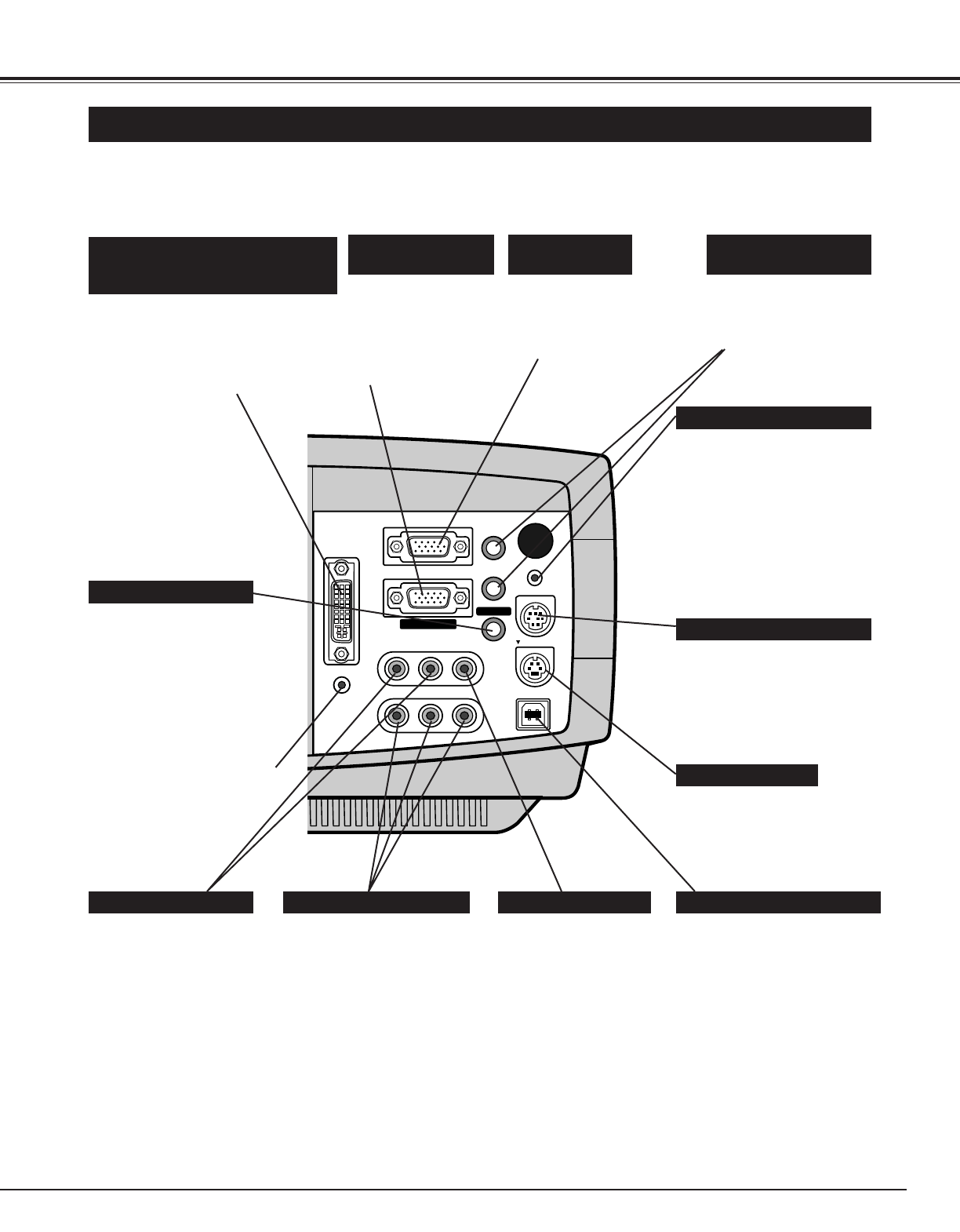
◆ Compatibility
This projector widely accepts various video and
computer input signals including;
● Computers
IBM-compatible or Macintosh computer up to 1280
x 1024 resolution.
● 6 Color Systems
NTSC, PAL, SECAM, NTSC 4.43, PAL-M or PAL-
N color system can be connected.
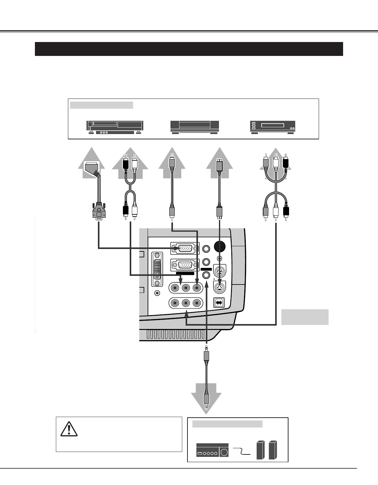
● Component Video
Component video signal, such as a DVD player
output high definition TV signals including 480i,
480p, 575i, 575p, 720p, 1035i or 1080i, can be
connected.
● S-Video
S-Video signal, such as a S-VHS VCR output
signal, can be connected.
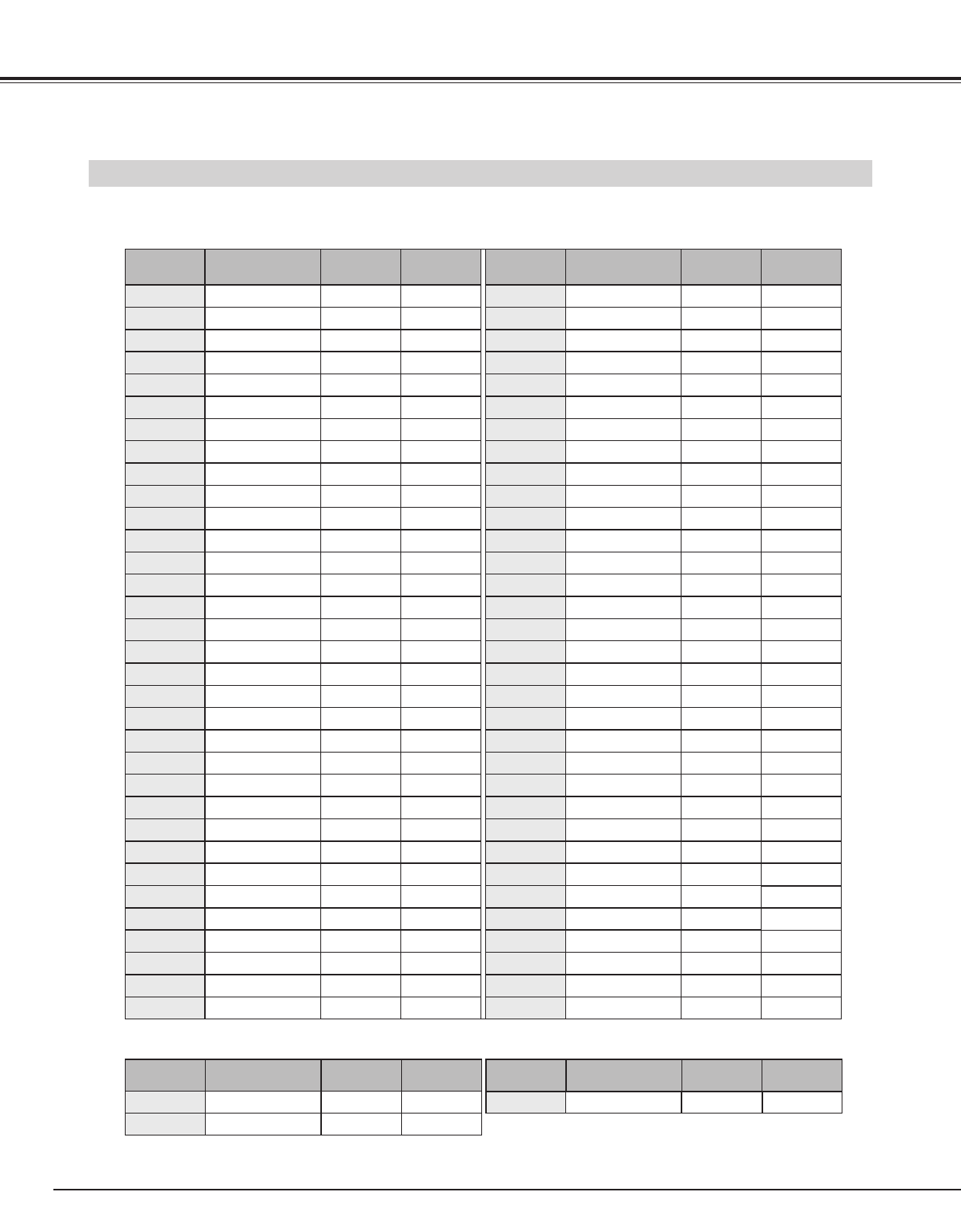
◆ High Resolution Image
This projector provides 1024 x 768 dots resolution for
computer input and 800 horizontal TV lines. Resolution
from a computer between XGA (1024 x 768) and SXGA
(1280 x 1024) is compressed into 1024 x 768 dots. This
projector cannot display image of over 1280 x 1024 dots.
When resolution of your computer is over than 1280 x
1024, reset a computer output for lower resolution.
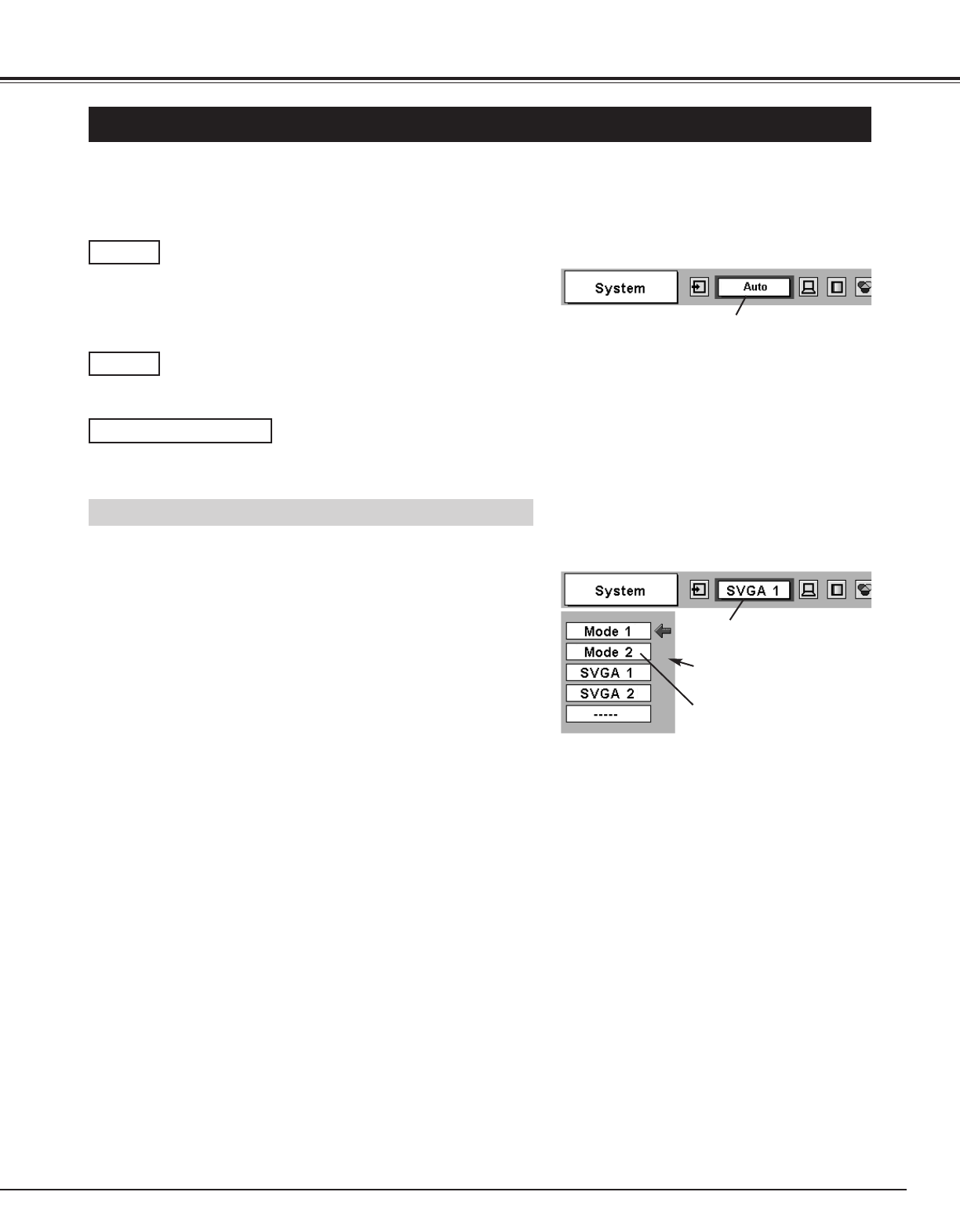
◆ Multi-Scan System
This projector has Multi-Scan System to conform to
almost all computer output signals quickly. There is no
need for troublesome manual adjustment of frequency
and other settings.
◆ Keystone Correction
Positioning of a projector may result in distorted image
being displayed in a trapezoid shape. Keystone
Correction solves this problem by digitally altering
projection to produce undistorted images.
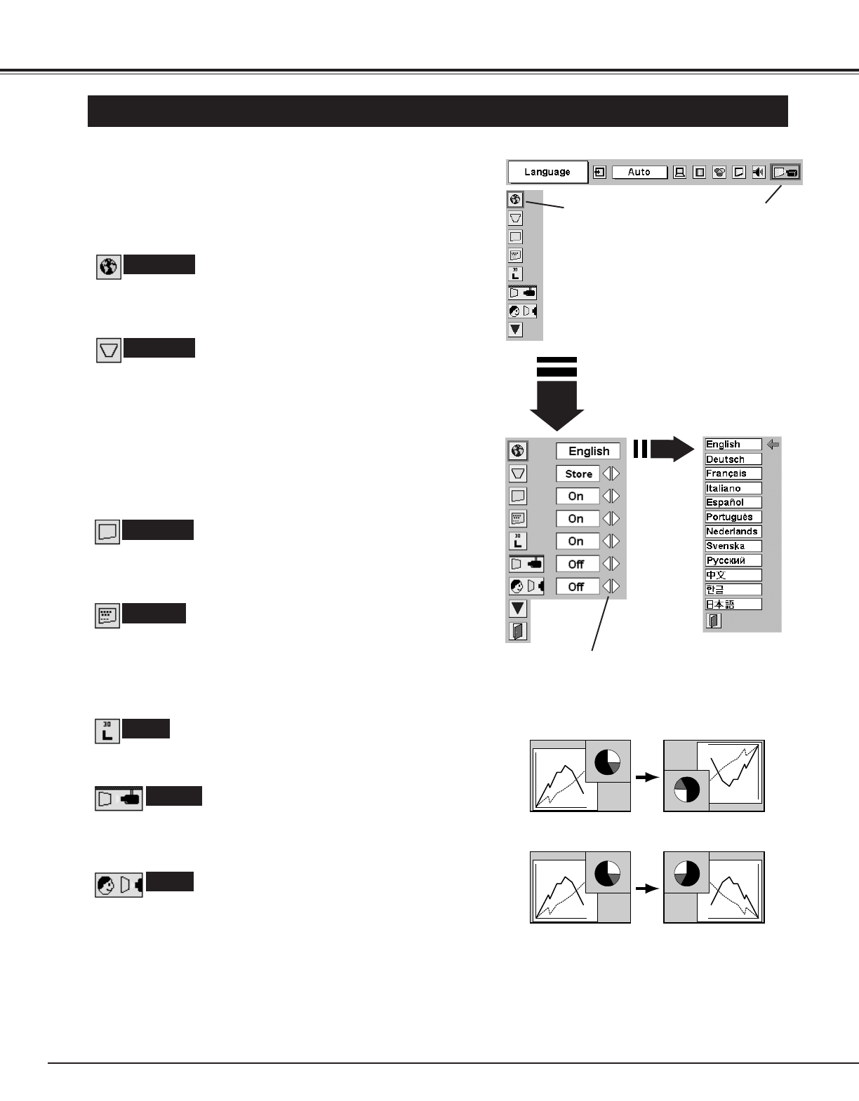
◆ Multilanguage Menu Display
Operation menu is displayed in; English, German,
French, Italian, Spanish, Portuguese, Dutch, Swedish,
Russian, Chinese, Korean or Japanese.
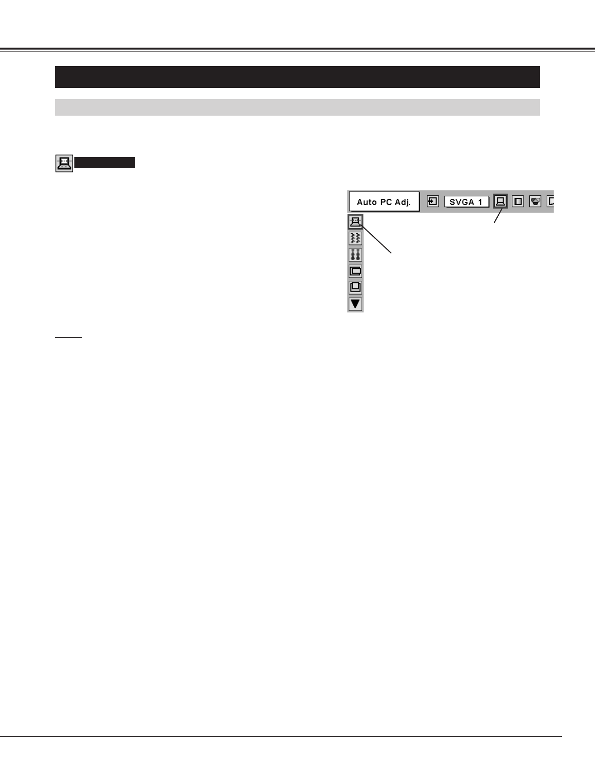
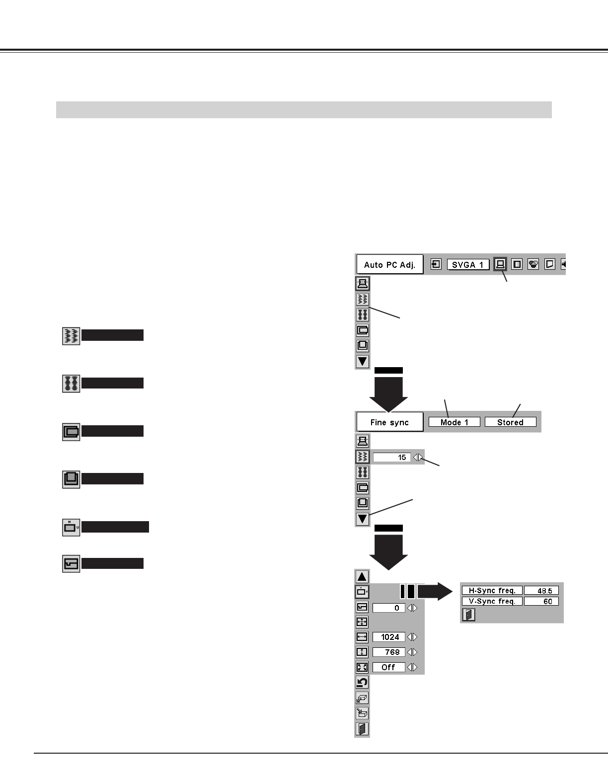
◆ One-Touch Auto PC Adjustment
Incoming computer video signals are recognized and the
best adjustment is automatically set by Auto PC
Adjustment. No complicated setup is necessary and
projection is always precise.
◆ Digital Zoom (for Computer)
Digital Zoom function adjusts the image size to approx.
1/4 ~ 49 times of original image size, allowing you to
focus on crucial information at a presentation.
◆ Compact Design
This projector is extremely compact in size and weight.
It is designed to carry and work anywhere you wish to
use.
◆ Power Management
Power Management function is provided to reduce power
consumption while a projector is not in use.
This Power Management function operates to turn
Projection Lamp off when a projector detects signal
interruption and any button is not pressed over 5
minutes. Projection Lamp is automatically turned on
again when a projector detects signal or any operation
button is pressed.
This projector is shipped with this function ON.
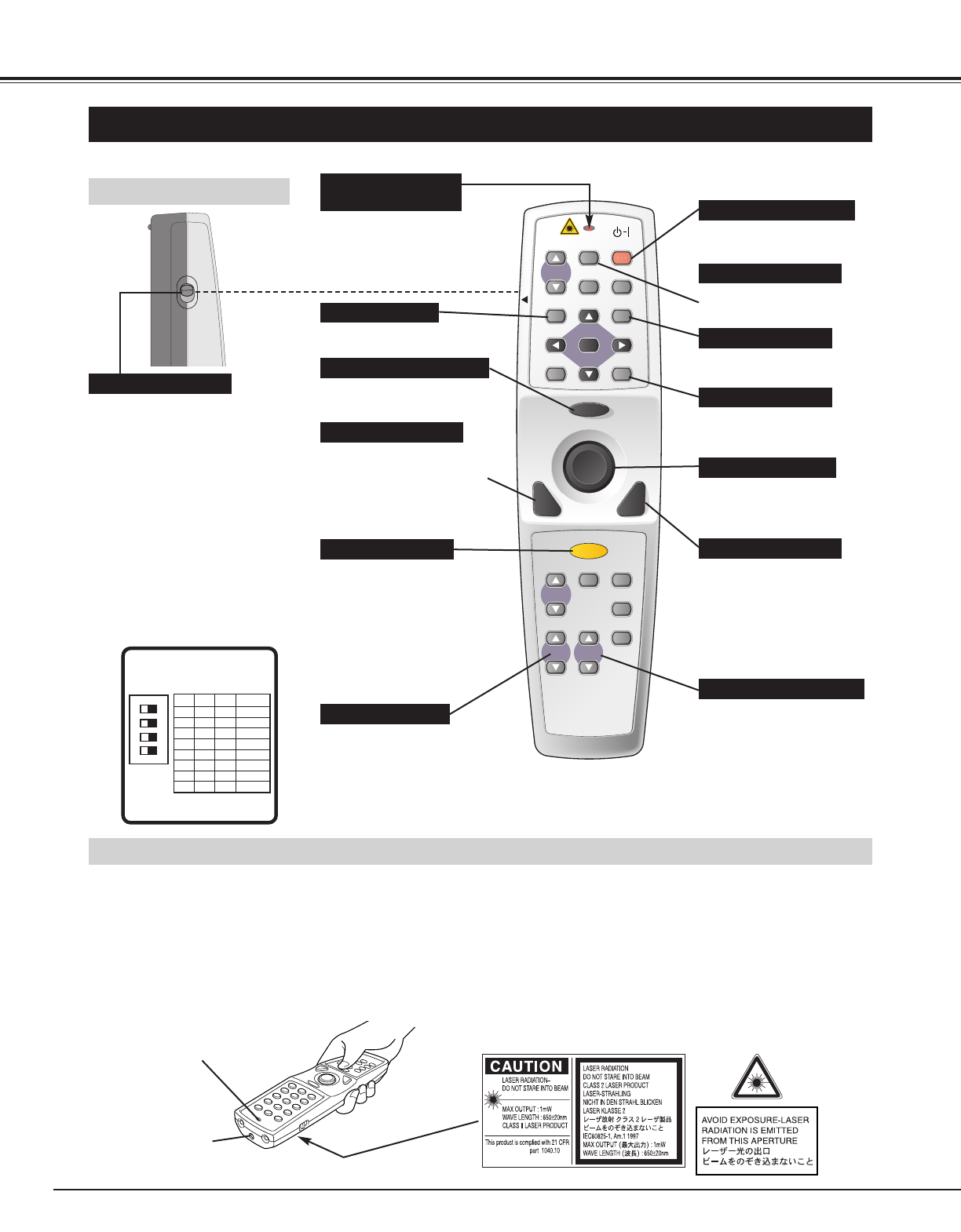
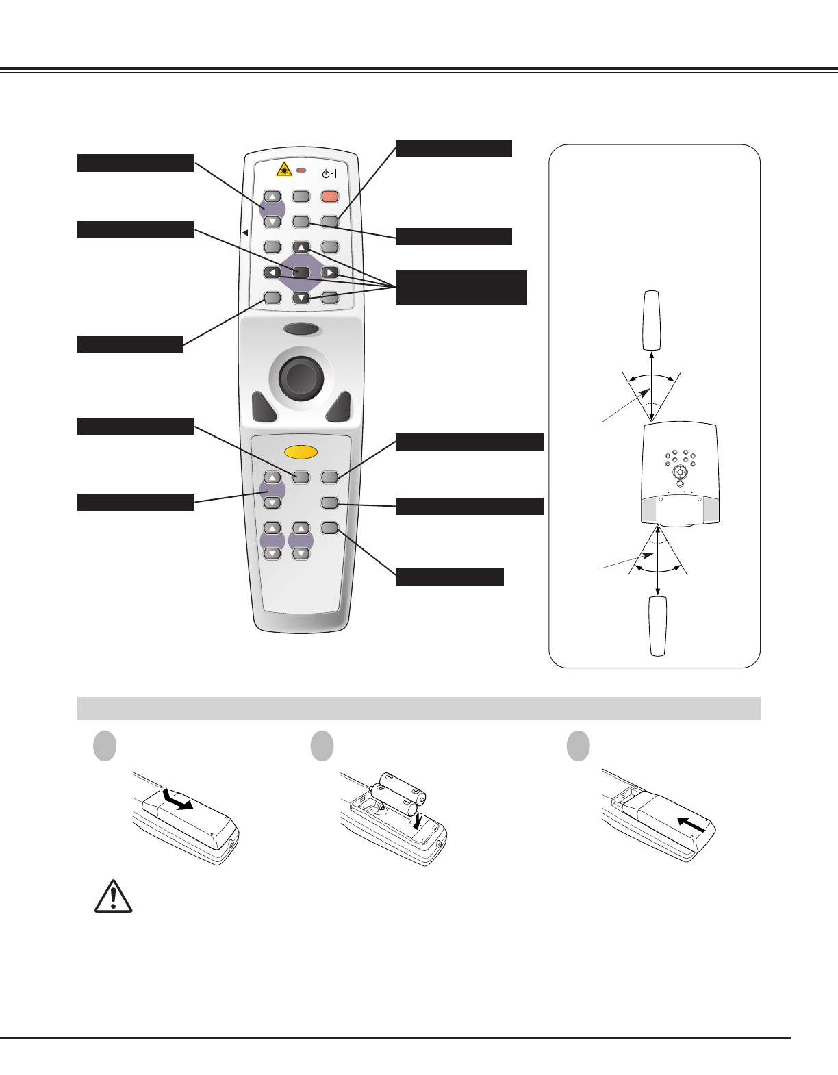
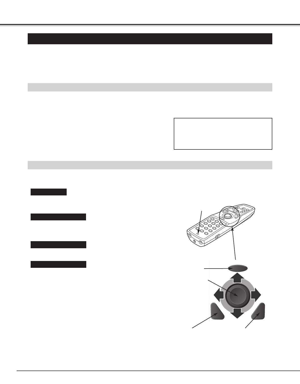
◆ Wireless Mouse
Remote Control Unit supplied with this projector has
Wireless Mouse function for a connected computer. This
function enables you to operate both projector and
computer with Remote Control Unit only.
◆ Digital Visual Interface
This projector is equipped with DVI 29-pin terminal for
connecting DVI output from a computer.
◆ Laser Pointer Function
Remote Control Unit supplied with this projector includes
Laser Pointer function. This function helps you to make
a smart presentation on a projected screen.
◆ Media Card Imager (Optional)
Optional Media Card Imager is available for this
projector. For the Media Card Imager, contact the sales
dealer where you purchased this projector.
◆ Wireless Imager (Optional)
This projector can be operated through Wireless LAN by
attaching Wireless imager that is optionally supplied. For
the Wireless Imager, contact the sales dealer where you
purchased the projector.
◆ Progressive Scan Function
This function converts interlace video signals into
progressive scan signals and provide fine picture quality.
◆ Motor-driven Lens Shift
Projection lens can be moved up and down with motor-
driven lens shift function. This function makes it easy to
provide projected image where you want.
Zoom and focus can be also adjusted with motor-driven
operation.
◆ PJ-Net Organizer (Optional)
PJ-Net Organizer is an optional product to control and
set up a projector via the network cable. By accessing to
the connected projector using the web browser on your
computer. It can be controlled and set up the projector
remotely. Contact the sales dealer where you purchased
this projector for optional parts.