82
Appendix
Numerics
2:2 Pulldown . . . . . . . . . . . . . . . . . . . . . . . . . . . . . . .47
2:3 Pulldown . . . . . . . . . . . . . . . . . . . . . . . . . . . . . .47
A
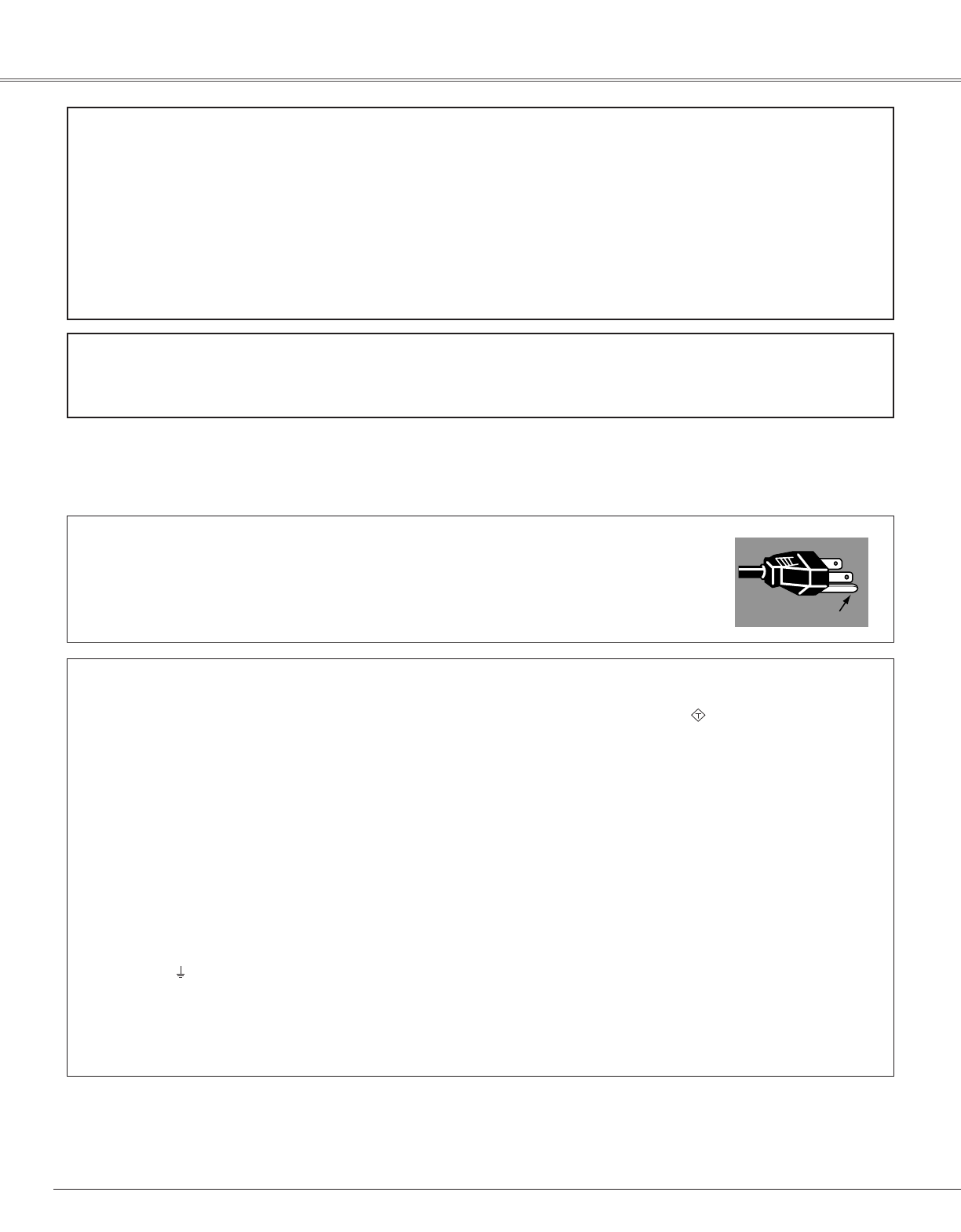
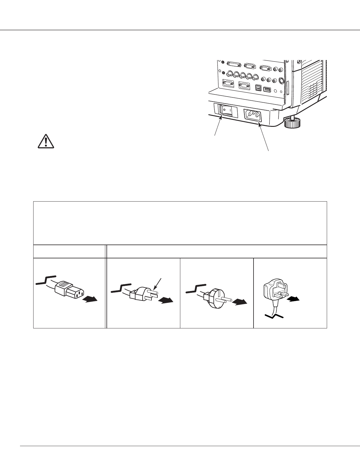
AC plug type . . . . . . . . . . . . . . . . . . . . . . . . . . . . . . .20
AC Power Cord . . . . . . . . . . . . . . . . . . . . . . . . . . .8, 20
Accessories . . . . . . . . . . . . . . . . . . . . . . . . . . . . . . .75
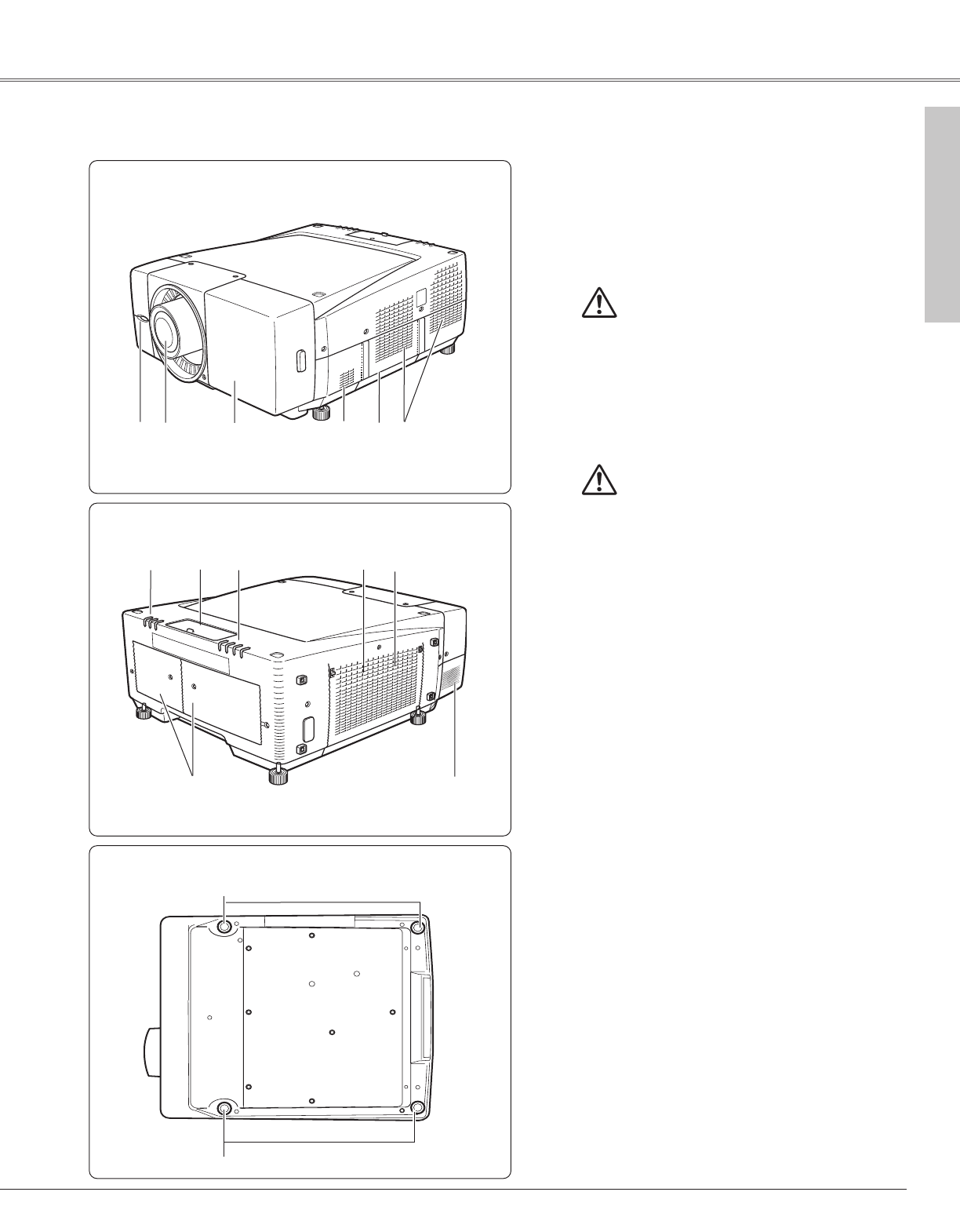
Adjustable Feet . . . . . . . . . . . . . . . . . . . . . . . . . . .9, 19
Analog out . . . . . . . . . . . . . . . . . . . . . . . . . . . . . . . . .55
Appendix . . . . . . . . . . . . . . . . . . . . . . . . . . . . . . . . . .70
Aspect setting . . . . . . . . . . . . . . . . . . . . . . . . . . . . . .48
Auto PC Adjust . . . . . . . . . . . . . . . . . . . . . . . . . . . . .41
Auto PC Adjustment . . . . . . . . . . . . . . . . . . . . . . . . .31
Auto picture control . . . . . . . . . . . . . . . . . . . . . . . . .46
AV System . . . . . . . . . . . . . . . . . . . . . . . . . . . . . . . .40
B
Bass . . . . . . . . . . . . . . . . . . . . . . . . . . . . . . . . . . . . .50
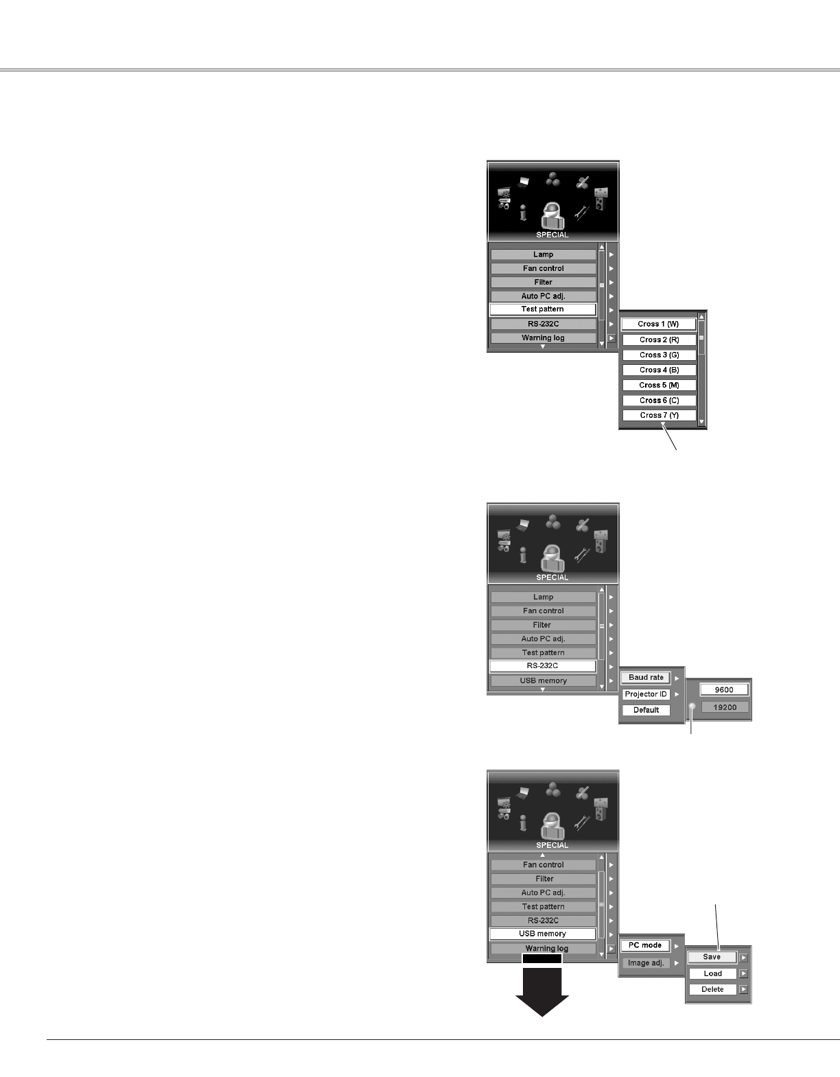
Baud rate . . . . . . . . . . . . . . . . . . . . . . . . . . . . . . . . .60
Brightness . . . . . . . . . . . . . . . . . . . . . . . . . . . . . . . . .45
C
Capture . . . . . . . . . . . . . . . . . . . . . . . . . . . . . . . . . . .52
Carrying Handle . . . . . . . . . . . . . . . . . . . . . . . . . . .7, 9
Ceiling . . . . . . . . . . . . . . . . . . . . . . . . . . . . . . . . . . . .49
Ceiling Mount . . . . . . . . . . . . . . . . . . . . . . . . . . . . . .79
Cinema . . . . . . . . . . . . . . . . . . . . . . . . . . . . . . . . . . .44
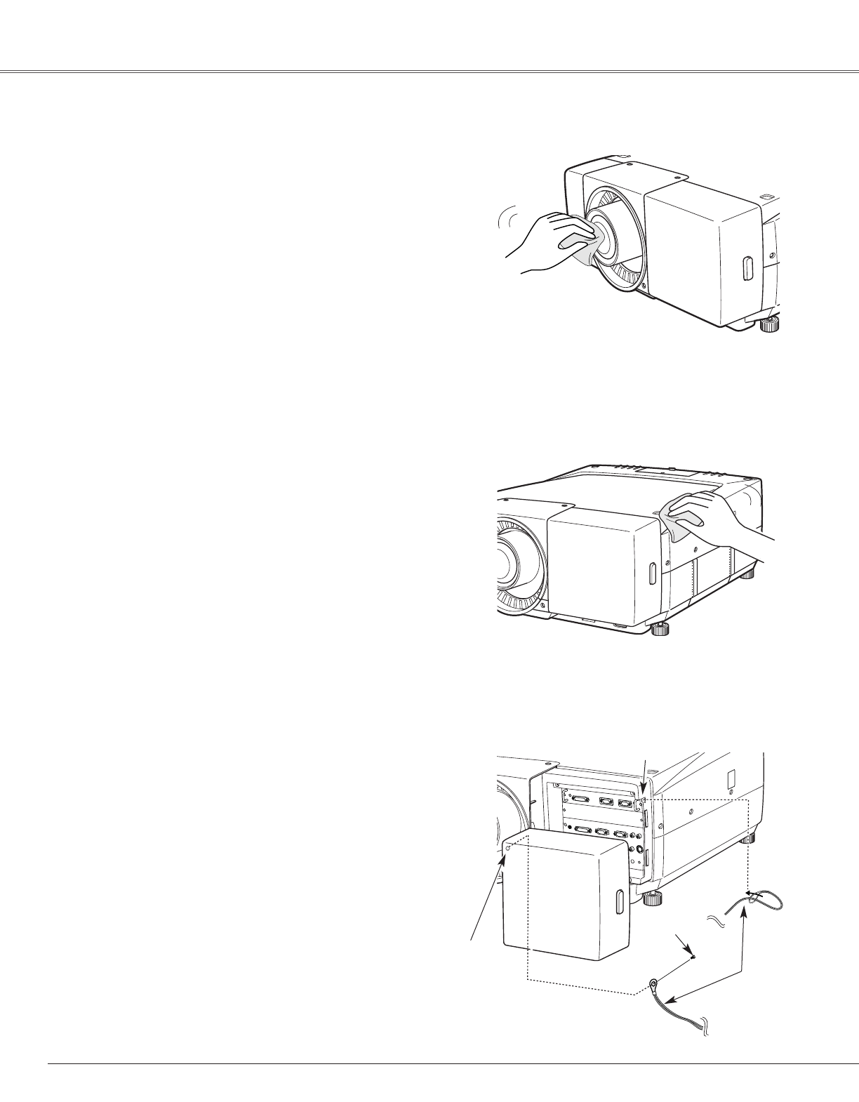
Cleaning . . . . . . . . . . . . . . . . . . . . . . . . . . . . . . . . . .66
Color . . . . . . . . . . . . . . . . . . . . . . . . . . . . . . . . . . . . .45
Color Management . . . . . . . . . . . . . . . . . . . . . . . . . .45
Color Management List . . . . . . . . . . . . . . . . . . . . . .46
Color Selection . . . . . . . . . . . . . . . . . . . . . . . . . . . . .45
Color System . . . . . . . . . . . . . . . . . . . . . . . . . . . . . .74
Color temp. . . . . . . . . . . . . . . . . . . . . . . . . . . . . . . . .46
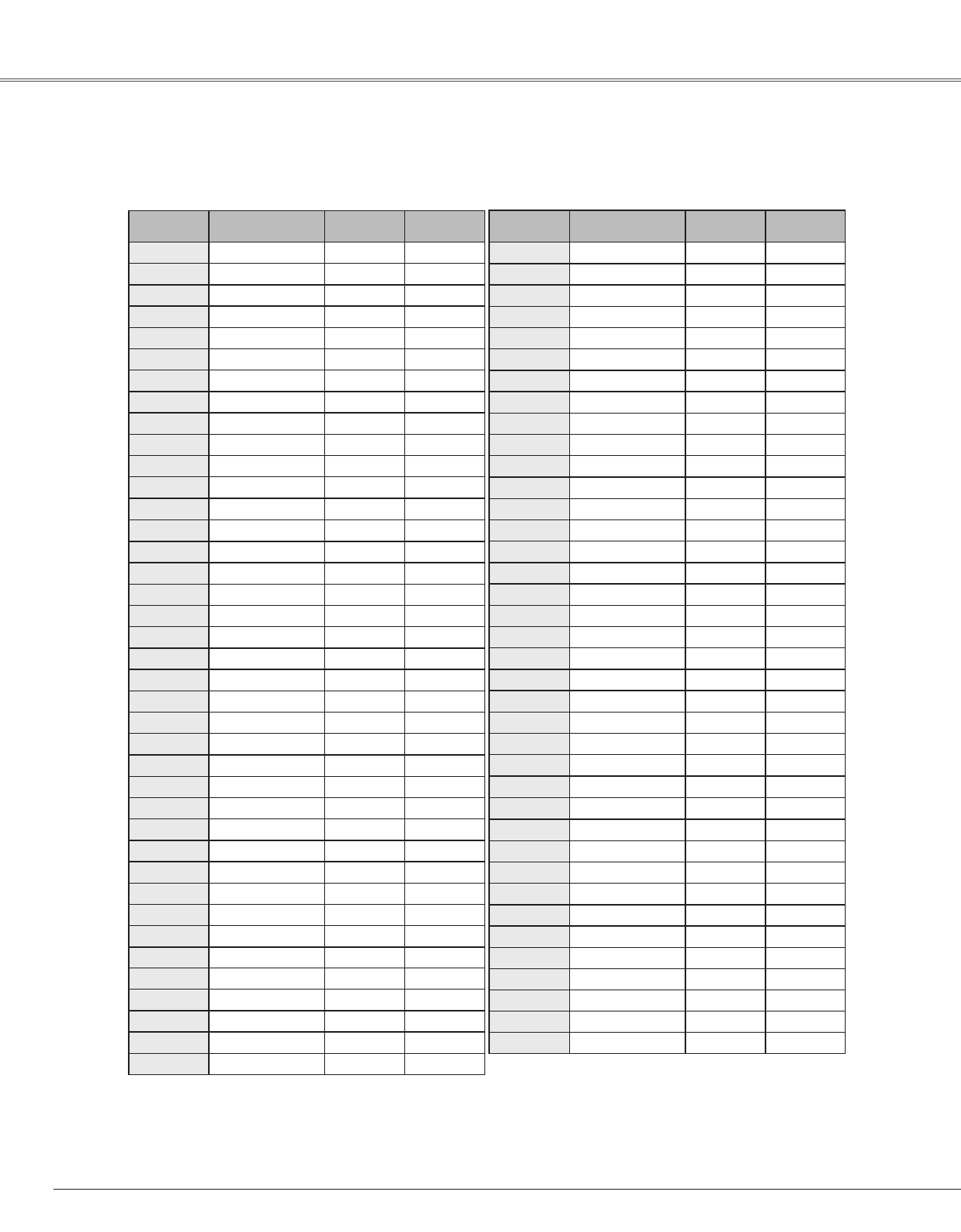
Compatible Computer Specifications . . . . . . . . . . . .72
COMPONENT . . . . . . . . . . . . . . . . . . . . . . . . . . . . . .40
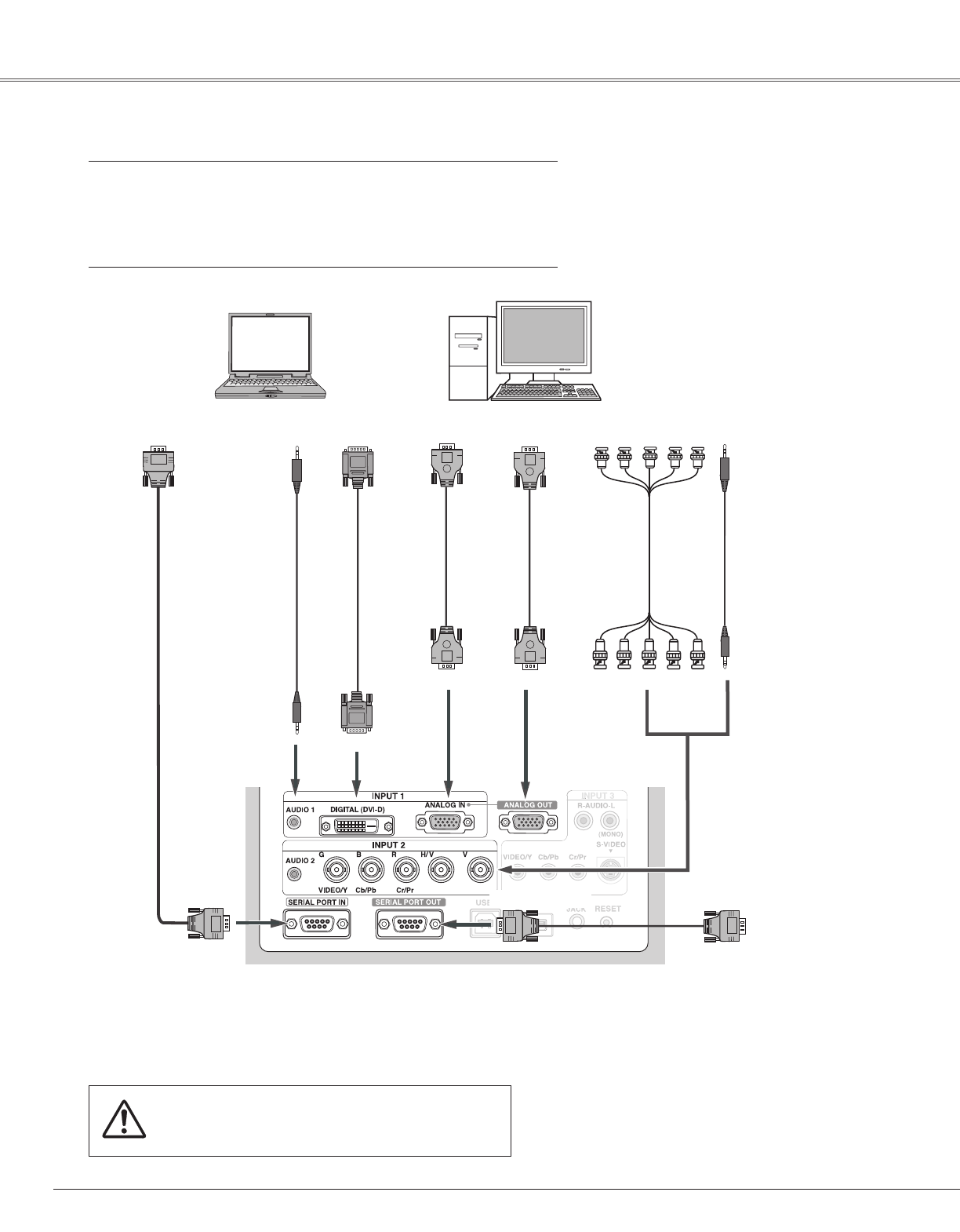
Connecting to Computer . . . . . . . . . . . . . . . . . . . . .22
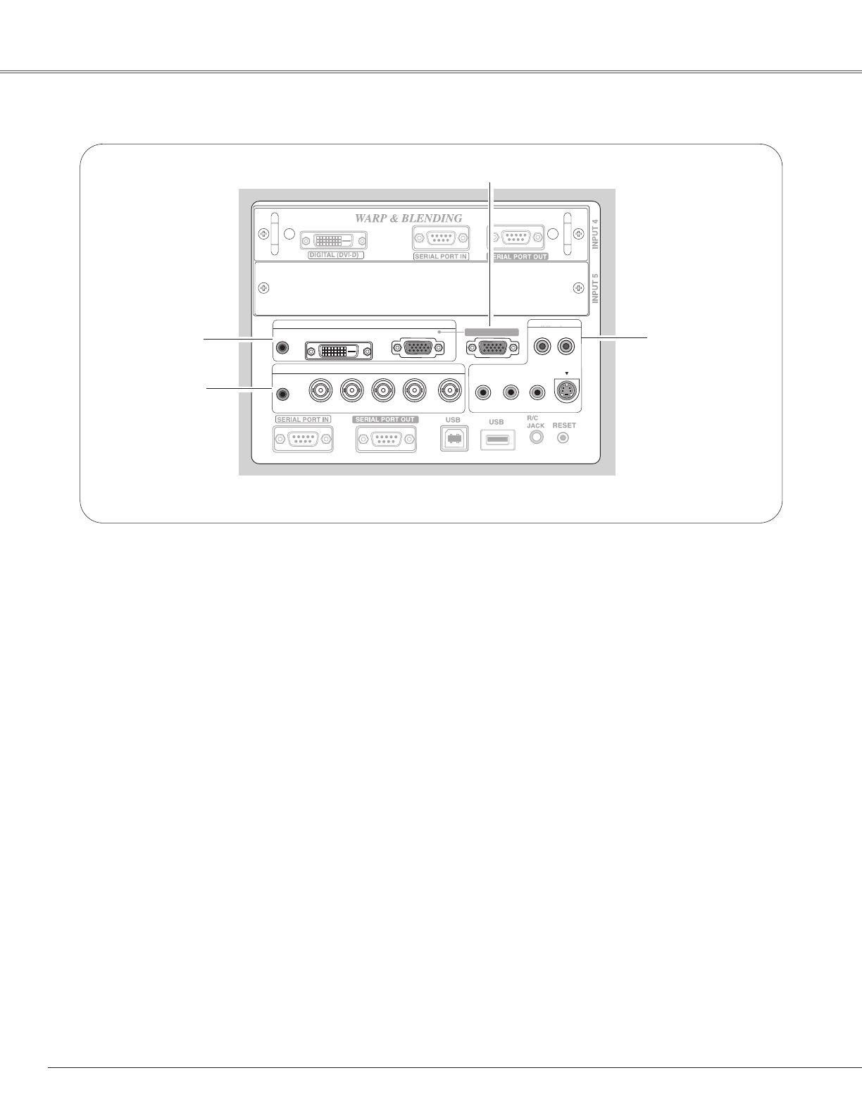
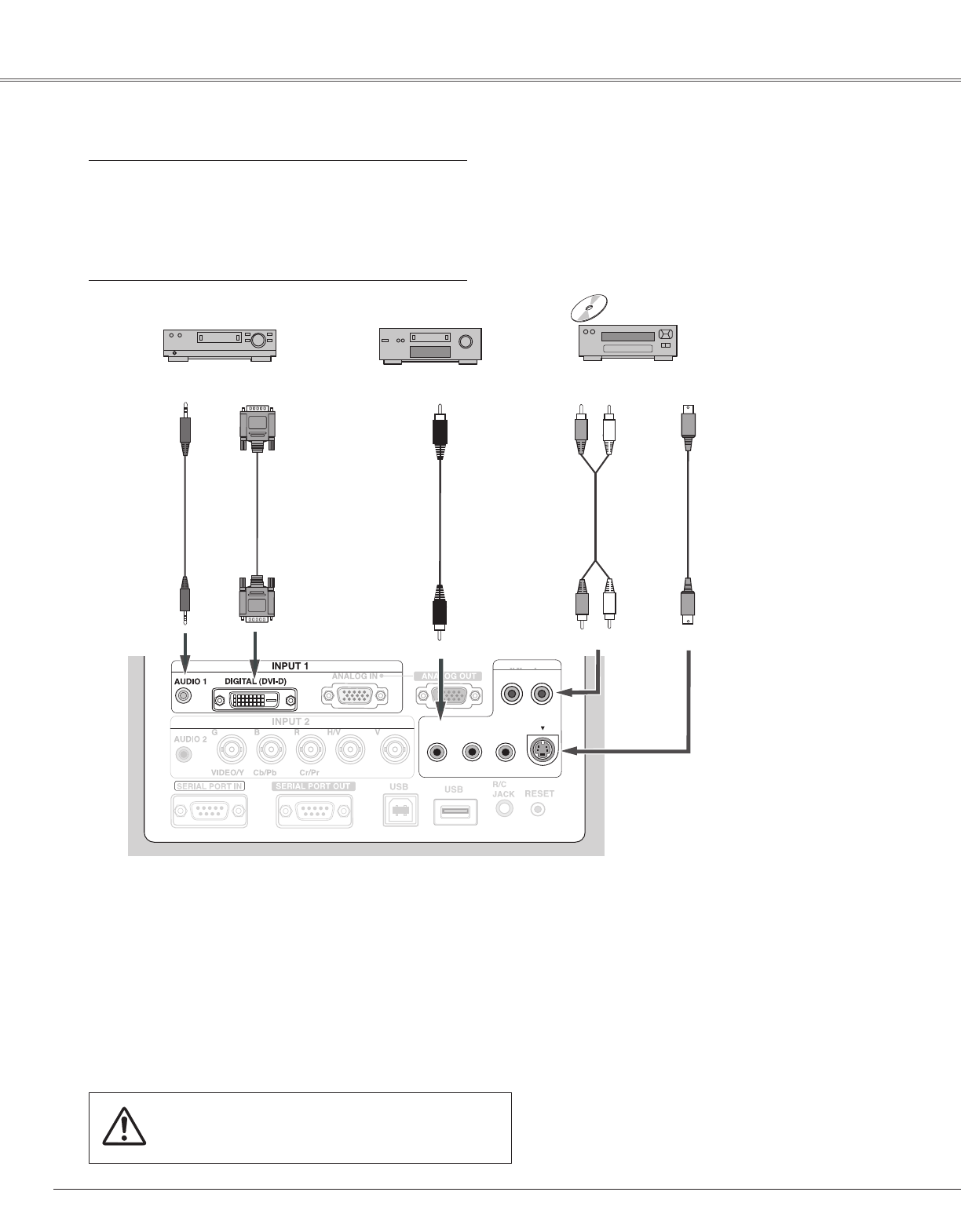
Connecting to Digital PC/AV Equipment . . . . . . . . .23
Connecting to Video Equipment . . . . . . . . . . . . .24, 25
Contrast . . . . . . . . . . . . . . . . . . . . . . . . . . . . . . . . . .45
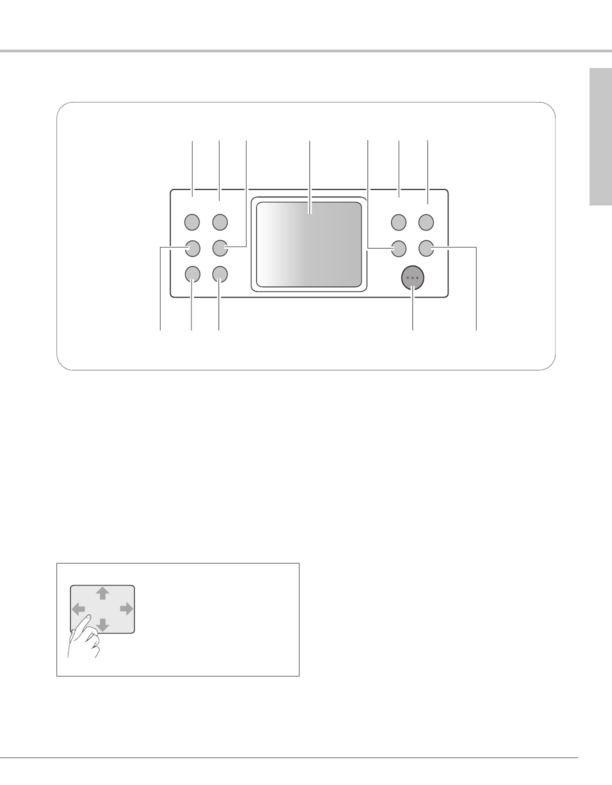
Control Pad . . . . . . . . . . . . . . . . . . . . . . . . . . . . . .2, 11
Cord Cover Strap . . . . . . . . . . . . . . . . . . . . . . . . . . .66
D
D-Zoom . . . . . . . . . . . . . . . . . . . . . . . . . . . . .27, 33, 49
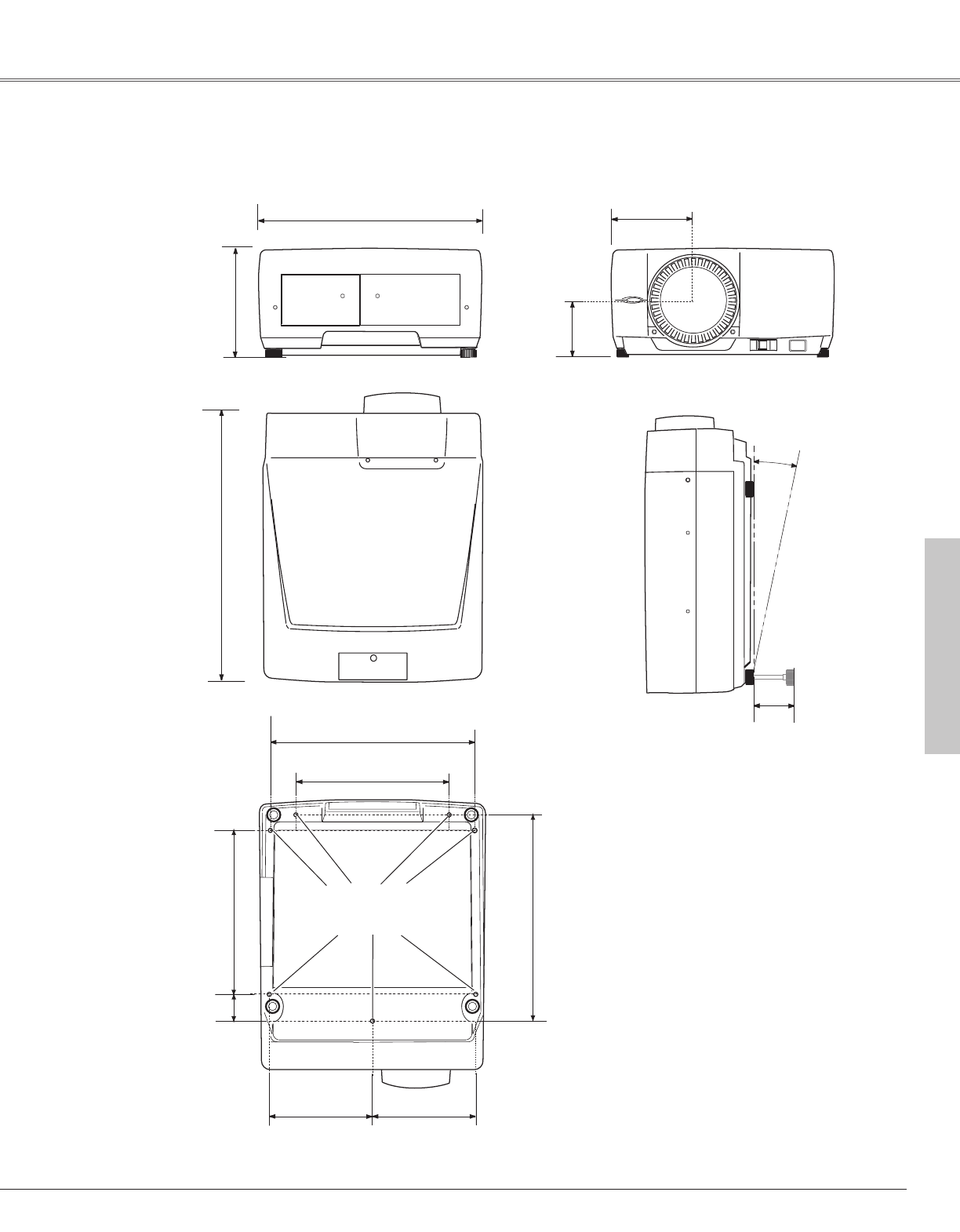
Dimensions . . . . . . . . . . . . . . . . . . . . . . . . . . . . .74, 79
Display . . . . . . . . . . . . . . . . . . . . . . . . . . . . . . . . . . .54
Dual SDI . . . . . . . . . . . . . . . . . . . . . . . . . . . . . . . . . .75
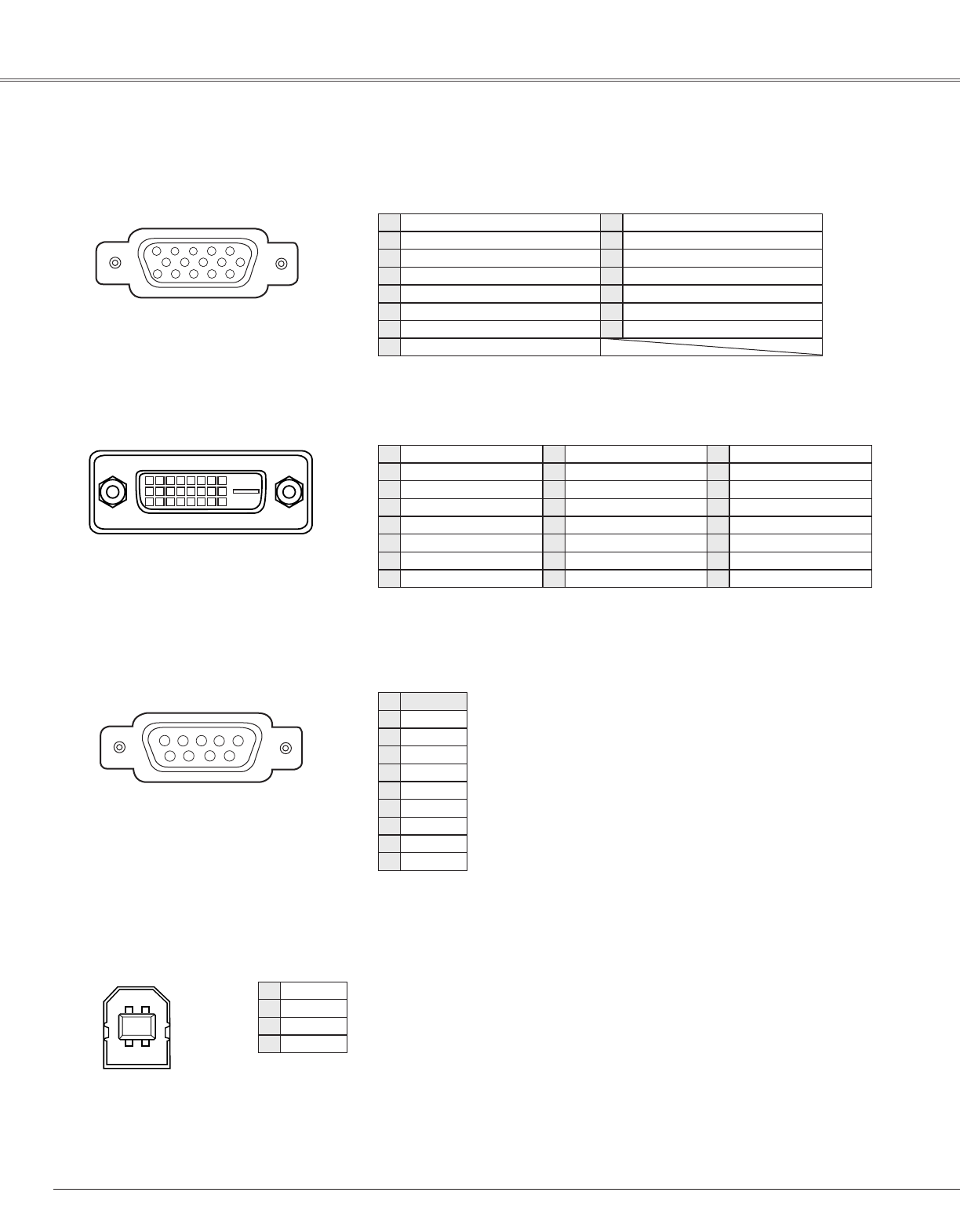
DVI-D . . . . . . . . . . . . . . . . . . . . . . . . . . . . . .12, 13, 80
F
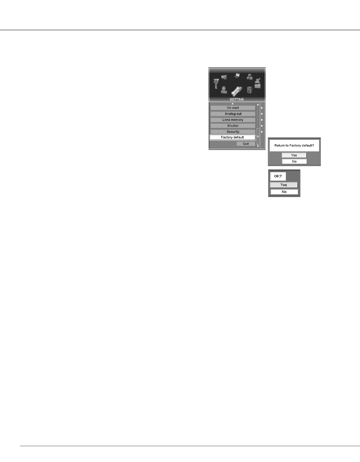
Factory default . . . . . . . . . . . . . . . . . . . . . . . . . . . . .58
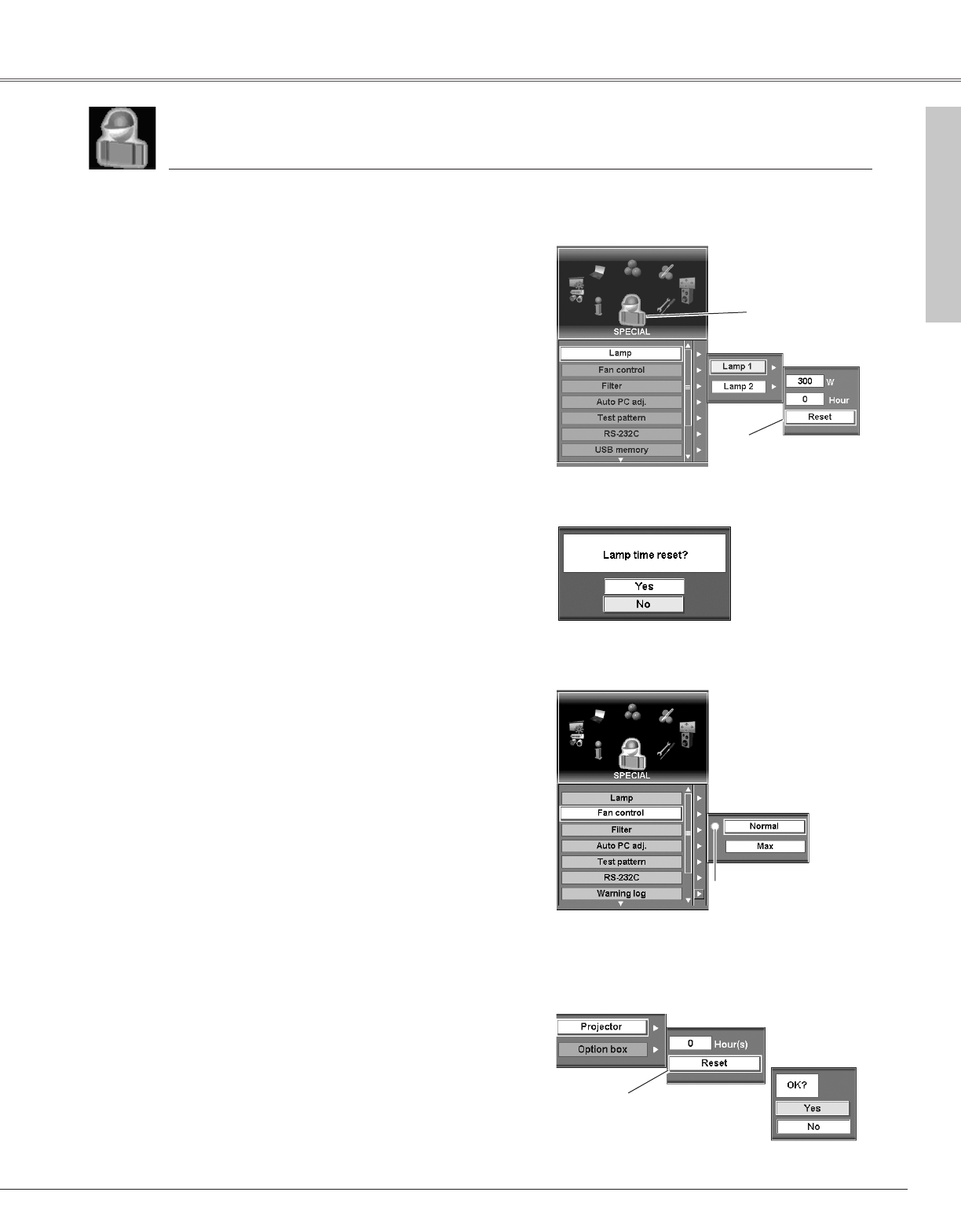
Fan control . . . . . . . . . . . . . . . . . . . . . . . . . . . . . . . .59
Faroudja . . . . . . . . . . . . . . . . . . . . . . . . . . . . . . . . . .75
Federal Communication Commission Notice . . . . . . .8
Film . . . . . . . . . . . . . . . . . . . . . . . . . . . . . . . . . . . .2, 47
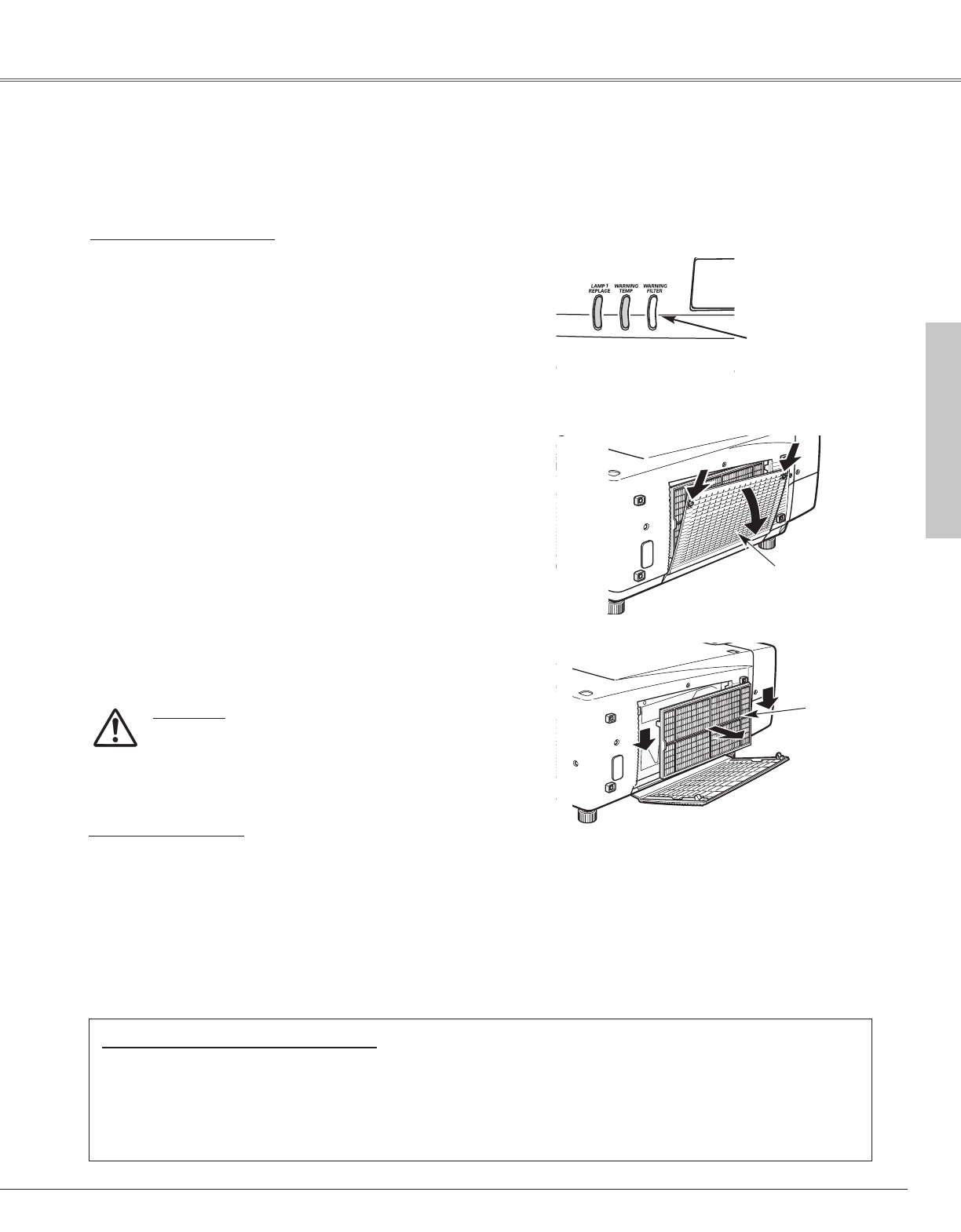
Filter . . . . . . . . . . . . . . . . . . . . . . . . . . . . . . . . . .59, 63
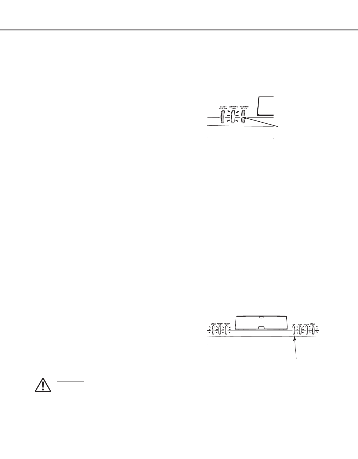
Filter Indicator . . . . . . . . . . . . . . . . . . . . . . . . . . . . . .68
Focus . . . . . . . . . . . . . . . . . . . . . . . . . . . . . . . . .27, 30
Freeze . . . . . . . . . . . . . . . . . . . . . . . . . . . . . . . . . . . .32
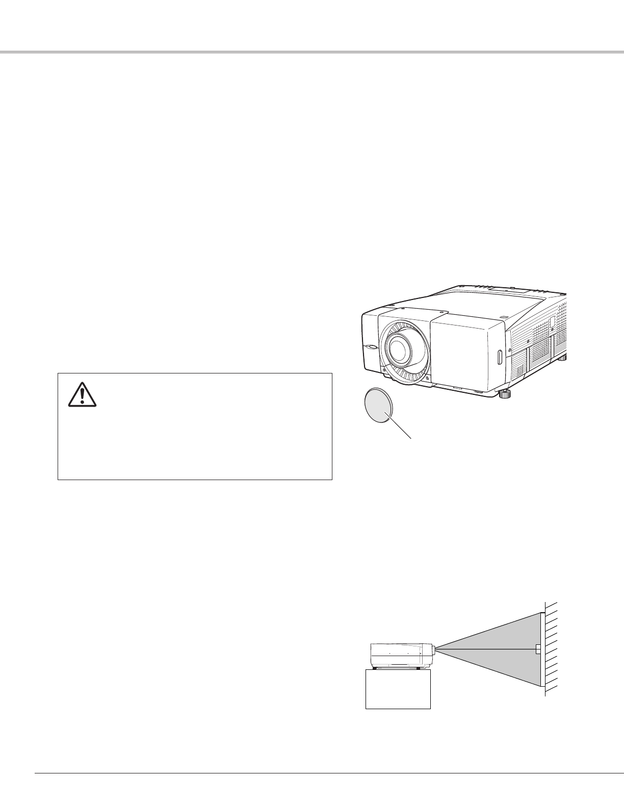
Front cover . . . . . . . . . . . . . . . . . . . . . . . . . . . . . . . .21
Full screen . . . . . . . . . . . . . . . . . . . . . . . . . . . . . . . .48
G
Gamma . . . . . . . . . . . . . . . . . . . . . . . . . . . . . . . . . . .47
H
H&V . . . . . . . . . . . . . . . . . . . . . . . . . . . . . . . . . . . . .48
Handling the Projector . . . . . . . . . . . . . . . . . . . . . . . .7
HDB15-PIN . . . . . . . . . . . . . . . . . . . . . . . . . . . . . . . .80
I
Image . . . . . . . . . . . . . . . . . . . . . . . . . . . . . . . . . . . .44
Image Adjust . . . . . . . . . . . . . . . . . . . . . . . . . . . . . . .45
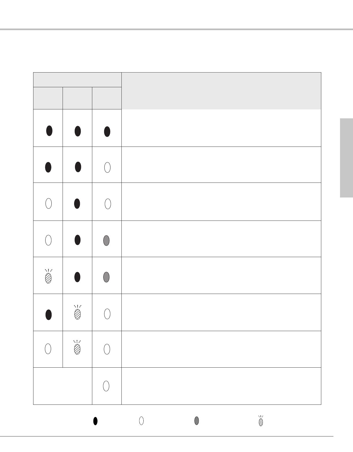
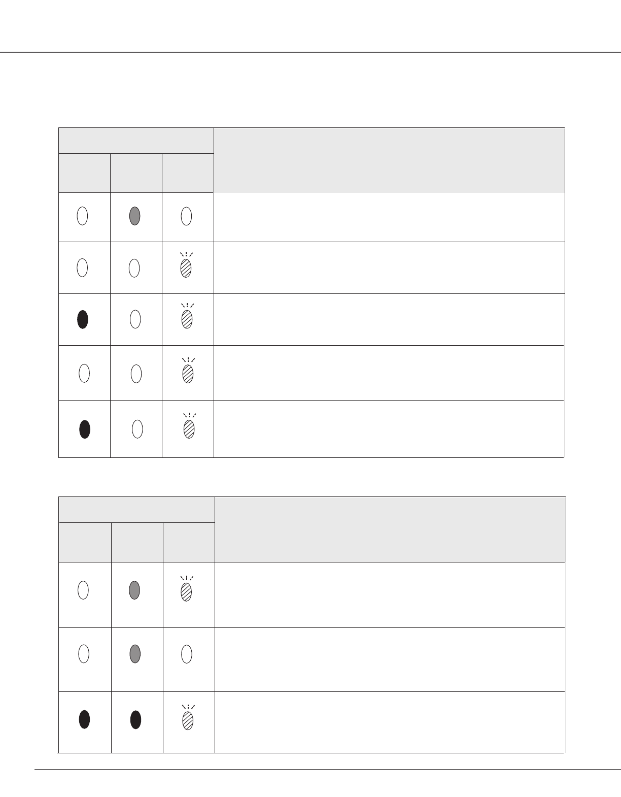
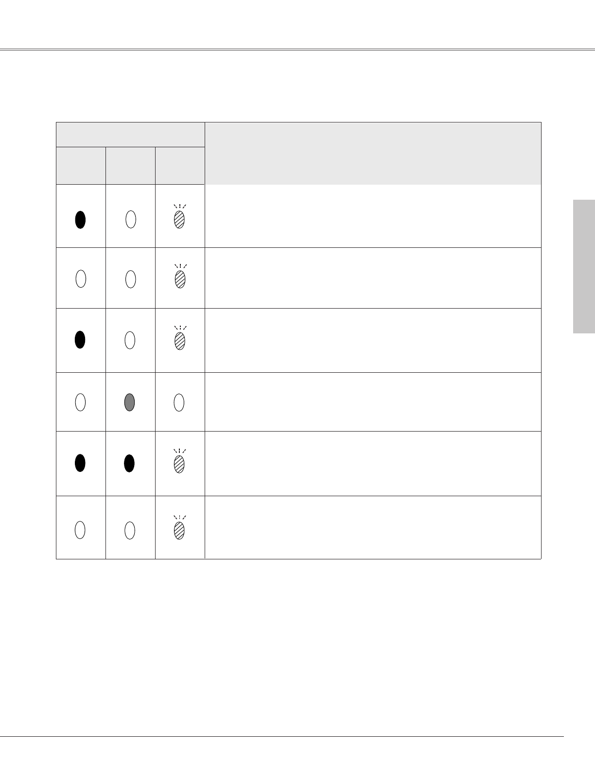
Indicators . . . . . . . . . . . . . . . . . . . . . . . . . . . . . .10, 67
Information . . . . . . . . . . . . . . . . . . . . . . . . . . . . .31, 61
Input . . . . . . . . . . . . . . . . . . . . . . . . . . . . . . . . . .31, 37
Input Search . . . . . . . . . . . . . . . . . . . . . . . . . . . . . . .54
Installation . . . . . . . . . . . . . . . . . . . . . . . . . . . . . . . . .18
Interface . . . . . . . . . . . . . . . . . . . . . . . . . . . . . . . . . .74
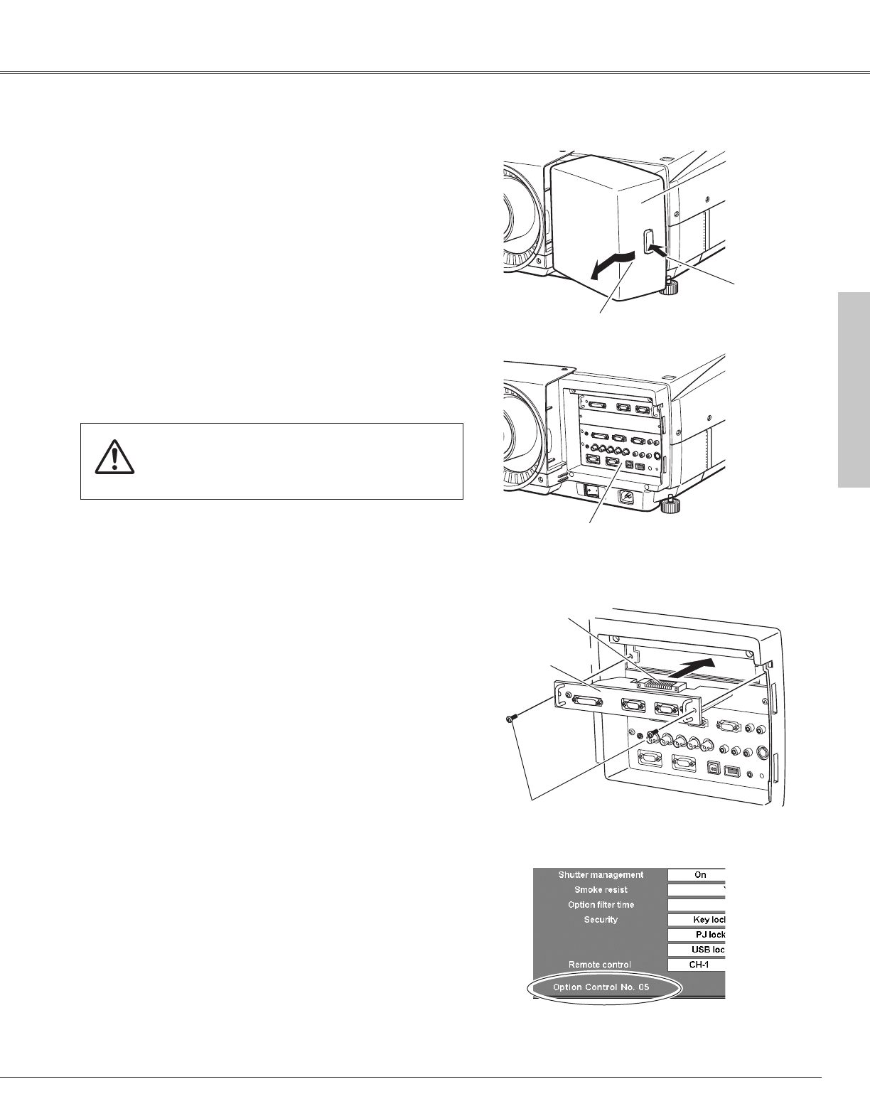
Interface Board . . . . . . . . . . . . . . . . . . . . . . . . . . . . .21
K
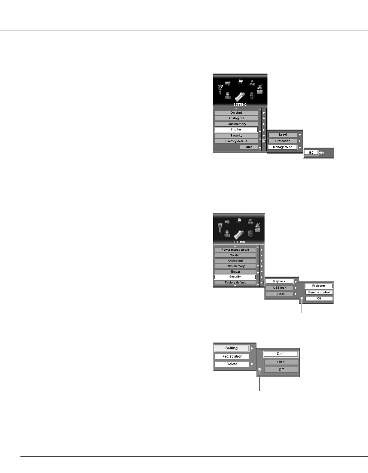
Keylock . . . . . . . . . . . . . . . . . . . . . . . . . . . . . . . . . . .56
Keystone . . . . . . . . . . . . . . . . . . . . . . . . . . . .27, 32, 49
L
Lamp . . . . . . . . . . . . . . . . . . . . . . . . . . . . . . . . . .53, 59
Lamp Control . . . . . . . . . . . . . . . . . . . . . . . . . . . . . .53
Lamp Mode . . . . . . . . . . . . . . . . . . . . . . . . . . . . . . .53
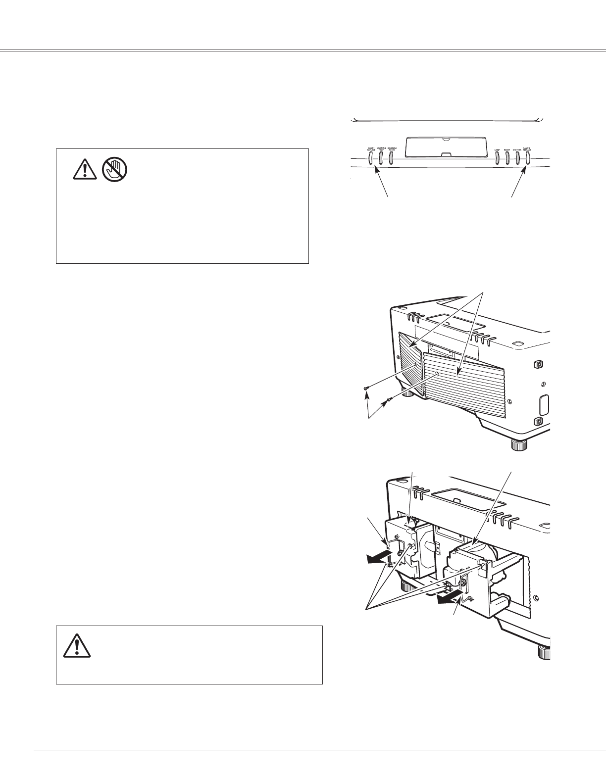
Lamp Replace Indicator . . . . . . . . . . . . . . . . . . . . . .69
Lamp Replacement . . . . . . . . . . . . . . . . . . . . . . . . . .64
Language . . . . . . . . . . . . . . . . . . . . . . . . . . . . . . . . .51
Lens Installation . . . . . . . . . . . . . . . . . . . . . . . . . . . .18
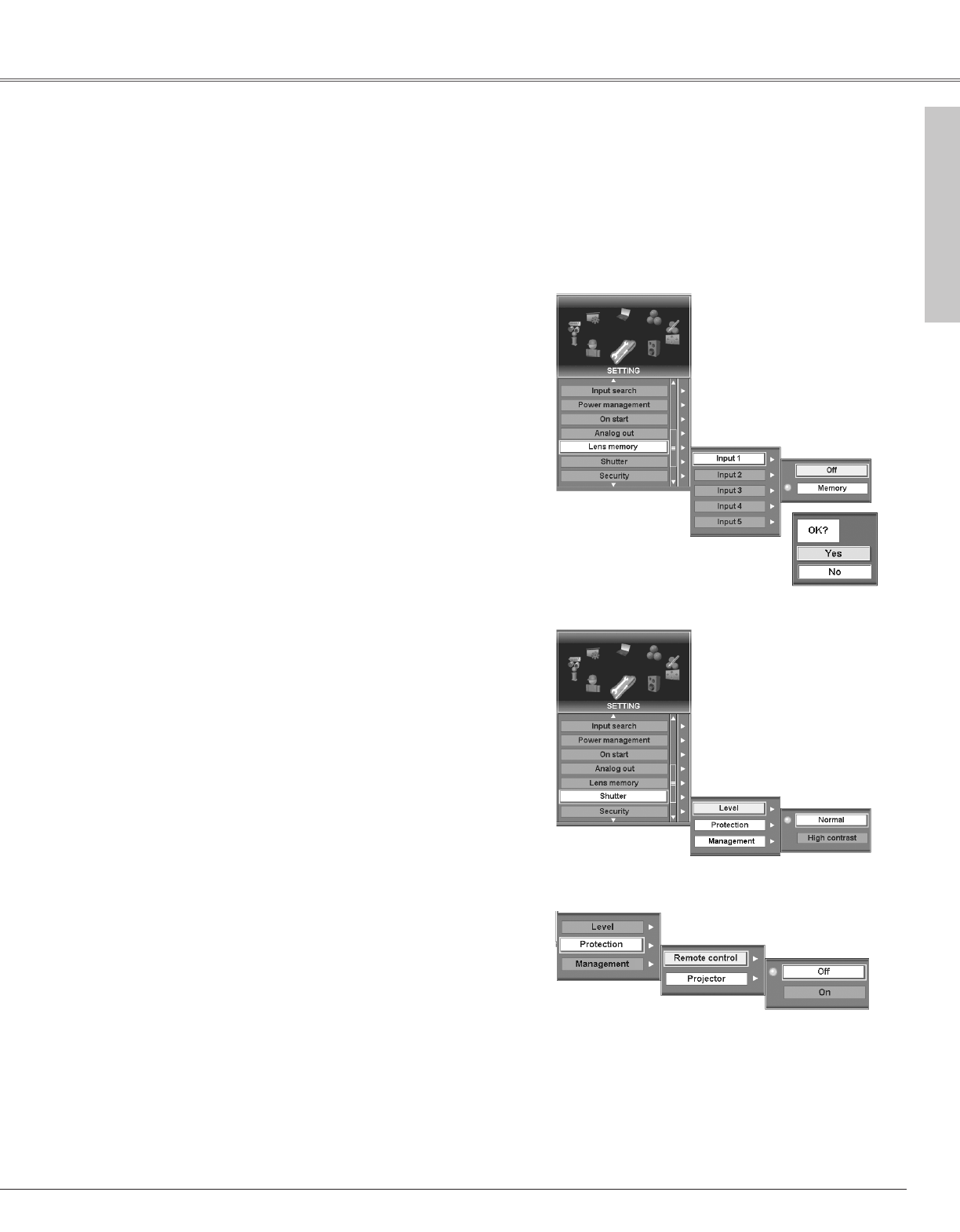
Lens memory . . . . . . . . . . . . . . . . . . . . . . . . . . . . . .55
Lens Shift . . . . . . . . . . . . . . . . . . . . . . . . .2, 19, 27, 30
Logo . . . . . . . . . . . . . . . . . . . . . . . . . . . . . . . . . . . . .52
Logo Lock . . . . . . . . . . . . . . . . . . . . . . . . . . . . . . . . .52
Logo PINcode . . . . . . . . . . . . . . . . . . . . . . . . . . . . . .52
Logo Select . . . . . . . . . . . . . . . . . . . . . . . . . . . . . . . .52
M
Manual PC Adjust . . . . . . . . . . . . . . . . . . . . . . . . . . .42
Menu . . . . . . . . . . . . . . . . . . . . . . . . . . . . . . . . . . . .51
Menu Icons . . . . . . . . . . . . . . . . . . . . . . . . . . . . . . . .36
Menu Position . . . . . . . . . . . . . . . . . . . . . . . . . . . . . .51
Index